1
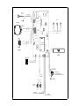
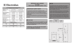
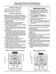
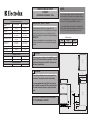
SERVICE DATA SHEET
41013617
REFRIGERATOR DRAWERS - R134a
PERFORMANCE DATA NO LOAD & NO DRAWER OPENINGS
AT MID-POINT CONTROL SETTINGS
Type A with Run/Start
Capacitor
Operating Time
Temperature
Low Side Pressure (cut-in)
Low Side Pressure (cut-out)
High Side Pressure
(last 1/3 cycle)
65° (18°C) Ambient
90° (32°C) Ambient
15 to 35%
35 to 55%
34°F to 42°F
34°F to 42°F
25 to 50 psig
172 to 345 kPa
25 to 50 psig
172 to 345 kPa
0 to 10 psig
0 to 69 kPa
0 to 10 psig
0 to 69 kPa
95 to 125 psig
655 to 862 kPa
130 to 175 psig
896 to 1207 kPa
Wattage (last 1/3 cycle)
55 to 80
55 to 80
Amps (running)
.45 to .85
.45 to .85
Base voltage
115 vac (127 vac max)
Watts
RPM
Amps
4.1
1280
0.06
EVAPORATOR FAN MOTOR
2550
The information provided herein is designed to assist
qualified repair personnel only. Untrained persons should not
attempt to make repairs due to the possibility of electrical
shock. Disconnect power cord before servicing this appliance.
IMPORTANT
If any green grounding wires are removed during servicing,
they must be returned to their original position and properly
secured.
Your Electrolux refrigerator drawers has been designed for
built-in installation. When built-in, your refrigerator drawers
do not require additional air space for top, sides or rear. In
either case, the front grille must NOT be obstructed.
To ease unit installation and removal, it is recommended
that the cabinet rough opening dimensions be increased by
at least ¼ inch over the dimensions given for the unit.
Unit Dimensions
Width
Height
Depth
237⁄8 inch
333⁄4 to 343⁄4 inch
263⁄8 inch
CAUTION
CONDENSER FAN MOTOR
1.08
IMPORTANT SAFETY NOTE
NOTE
0.09
All electrical parts and wiring must be shielded from torch
flame. DO NOT allow torch to touch insulation; it will char
at 200°F and flash ignite (burn) at 500°F. Excessive heat
will distort the plastic liner.
Top
View
WARNING
Double drawer refrigerator drawers are designed to be
built-in only. They cannot be used for free-standing.
The screw supplied with the Anti-Tip Kit are for mounting the bracket to a wood floor. This screw will not work
if used with sheetrock (dry wall) or anything other than
wood.
263⁄8"
2323⁄32"
237⁄8"
21½"
Front
View
333⁄4"
Adjustable to
343⁄4"
Side
View
IMPORTANT: PLEASE RETURN THIS SHEET
TO IT'S ORIGINAL LOCATION.
37⁄16"
23⁄4"
395⁄32"
SERVICE
CORD
BLACK (SMOOTH)
GREEN
BLACK (RIBBED)
LIGHTS
GROUND
RED
BLU
RED
BLU
RUN
CAPACITOR
RED
BLU
COMPRESSOR
WHITE
RED
WHITE
WHITE
WHITE
B
RED
BLUE
RED
WHITE
BLUE WIRE PIN 2
WHITE WIRE PIN 3
COMM.
CONDENSER
FAN
USER
INTERFACE
BLACK
RED
RED
RING SPRING
BLACK
BLACK
WHITE
BLACK
BLUE
FAN LOW
PROGRAMMING/
DATA ACQUISITION PORT
(MODELS WITH RS485 BOARDS ONLY)
DOOR
SENSOR
TIP SPRING
SWITCHES
(RD ONLY)
SWITCH
LOW
EVAPORATOR
DEFROST SENSOR
WHITE
WHITE
WHITE
WHITE
SWITCH
UP
WHITE
WHITE
CABINET
TEMP SENSOR LOW