1
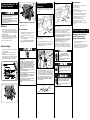
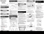
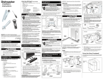
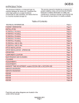
Dishwasher
Installation Preparation
2
1.
Remove two (2) screws at front of the kickplate using a #2
Phillips screw driver.
2.
Tilt and pull forward to remove see figure 1a.
6. If levelers need to be removed, make sure that the floor is free of all
obstructions.
Do not use the furnished drain hose or a rubber garden hose
for the water supply line. Either of these hoses can burst.
Flooding may occur and cause property damage.
333/4”
273/8”
NOTE: It is not necessary to remove the outer door for installation.
Printed in U.S.A.
675000800908
05/10
23”
Property Damage
NOTE: Put unit on its back being careful not to pinch the Water
Drain Hose.
Installation
Instructions
503/8”
27”
233/4”
Figure 3
Leveling and Securing
Dishwasher within
Cabinets
*DIMENSIONS DO NOT INCLUDE INSULATION
INSTALLER: Leave Installation Instructions with owner.
IMPORTANT: For proper operation and appearance of unit,
cabinet opening should have dimensions as shown in Figure 2.
If unit is to be placed in a corner, there must be at least a 2-inch
side clearance to open door.
OWNER: Read your dishwasher Use and Care Manual. It contains
important safety information for operating this appliance. It also has
many suggestions for getting the best results from your dishwasher.
Before You Begin
5
IMPORTANT: Drain, water, and electrical lines should be
roughed-in before going any further.
7. Carefully place dishwasher inside cabinet area such that is
centered in opening. Use caution when moving dishwasher to
prevent damage to cabinet, dishwasher and floor.
8. Front of door needs to be even with the front of adjoining cabinets.
Front levelers should allow 5/16” below underside of countertop
to top of console.
9. Check that dishwasher is level from side to side by placing a level
against the top front section of the tub. See Figure 5a.
Figure 5a
Figure 5b
Read all instructions before installing dishwasher.
For your safety, please read and observe all safety
instructions. This guide will help you anticipate drain, water, and
electrical connections, and help you select the best location for the
dishwasher.
Figure 1a
Electric Shock Hazard
Electrical, water, and drain lines must be confined
to shaded areas in Figure 2.
Electric conductors, water, and drain could be
damaged.
Failure to follow these instructions could result in
fire or electric shock.
Tip Over Hazard
Do not use dishwasher until completely installed.
1. Measure height of cabinet opening from underside of countertop
to floor.
10. Check that the dishwasher is level from front to back by taking
out the lower rack, place level on the lower rack wheel support at
the bottom of the tub. See Figure 5b.
2. Move dishwasher to front of installation area.
11. Adjust levelers up or down until dishwasher is level.
3. Loosen the rear leveling legs by turning counterclockwise.
Holes need to be pre-drilled using a #5 drill to secure
unit.
Dishwasher Anchoring
Do not push down on open door.
provided in literature packet. See Image Below.
NOTE: If dishwasher is installed at end of a cabinet, sides and
back must be fully enclosed.
Failure to follow this warning can result in serious
injury.
Connections For Electrical,
Water, and Drain
Figure 1b
Cut Hazard
To prevent serious injury from sharp edges, wear work
gloves when handling, unpacking or disassembling unit.
Installation Tips
1
Tools and Materials Needed for
Installation (Not Included)
•
•
•
•
•
•
•
•
•
•
•
•
•
•
•
Drill, Electric
Driver, Socket 5/32”, 1/4” , 5/16”
Flaring Tool / Tube Cutter (for copper tubing)
Flashlight
Level
Pipe Joint Compound (for iron pipe plumbing) or
Pipe Thread Tape (for sealing threads)
Pliers
Safety Glasses
Saw, Keyhole or 1/2”, 11/2” to 2” Hole Cutters
Screw Drivers, Slotted and #2 Phillips (magnetic tip
preferred)
Tape, Electrical or Duct
Tape, Measuring
Wire Stripper or Utility Knife
Wrench, Hex-end
Wrenches, 2 Adjustable (for copper tubing)
or 2 Pipe wrenches (for iron pipe plumbing)
Parts You Will Need* (Not Included)
• Brass Elbow, 90° with a 3/8” National Pipe Thread
• Conduit Connector (UL Listed)
• Wire Nuts, three (3) for 12-14 gauge wire (UL Listed)
*
12. Screw mounting brackets firmly to cabinet using screws
3. Remove two (2) screws at front of the kickplate brace using a
#2 Phillips screw driver. Slide up and pull off.
4. Locate water inlet valve behind kickplate on bottom left
underside of unit.See Figure 4. The valve has a 3/8” NPT female
fitting.
5. Wrap 90° elbow (not included) with pipe thread tape (or apply
joint compound) and thread it into water inlet valve. When
tightened, elbow should point toward the left. To prevent bending
of bracket or breaking of valve, avoid overtightening.
See Figure 4.
Cabinet Preparation:
As a precaution, it is recommended, but not required that the
cabinets enclosing all sides of the dishwasher (including the
underside of the countertop) be sealed with an oil based paint
or moisture-proof polyurethane to prevent possible steam/
moisture damage.
3
Roughing In
4
Choose one of the methods of attachment below to secure unit,
holes need to be pre-drilled using a #5 drill bit regardless of
the option chosen:
a. Top Mount Cabinet Clips (Preferred Method of attachment)
b. Side Mount Cabinet Clips (to be used when Top Mount
is not an available option)
CAUTION: Use extreme care in mounting the dishwasher as
to not scratch, bump or otherwise damage the console or tub.
Locating the Connections
1. Review dimensions in Figure 2 to locate dishwasher’s drain,
water, and electrical connections.
2. All utilities must be routed in shaded area in the Figure 2.
IMPORTANT: Disconnect power before starting installation.
To install using Top Mount Cabinet Clips:
Depending on the depth of cabinet, the Top Mount
Clip have a break off point that can be removed if
necessary.
Note: Locate the electrical supply and dishwasher’s electrical
junction box on right underside of unit behind kickplate
assembly. See Figure 4. Determine where you will connect
to hot water supply. Review Figure 4 and note the location of
water inlet valve. Determine where you will connect the drain
hose.
NOTE: Install Top Mount Clips before unit is installed into the
cabinet. Insert the installation brackets to the front
top slots of the dishwasher. (See image below)
Figure 5c
Figure 5d
13. Open the door remove the tub cap on both sides of the tub.
Install screw through the dishwasher side hole to the wall of
cabinet. Reinstall tub cap.
3. Cut access holes for the Electrical, Water and Drain hoses in the
shaded areas as shown in Figure 2.
4. The dishwasher operates on a 120 volt, 60 Hz electrical supply.
Provide a separate circuit with a fuse or circuit breaker rated for
at least 15 amps (20 amps if connected with disposer) but not
more than 20 amps.
5. Pull electrical cable through hole into installation area.
6. Be sure water inlet valve is protected from freezing. If valve
freezes and ruptures, flooding may occur.
Electric Shock Hazard
Observe all local codes and ordinances for
electrical and plumbing connections. All electrical
and plumbing work should be performed by
qualified persons. Failure to follow this warning
could result in death or serious injury.
7. Determine amount of tubing needed to connect hot water supply
to the unit’s water inlet valve. Extra hose length is necessary.
High-pressure and high-temperature Stainless Flexible hose with
a minimum inner diameter of 1/4” may be used. A shut-off valve
installed outside dishwasher cabinet is best.
9. Stand dishwasher back upright for further installation.
1. Make sure your location has the correct drain, water, and
electrical outlets to make the connections. Do not install unit
under a cooktop range. Damage to tub or other components will
occur.
IMPORTANT: Incoming hot water temperature should be at
least 120°F (49°C). Water pressure should be between
20–90 psi.
2. Floor should be flat and free of any obstruction.
• “Y” Branch Tailpiece and
Connector Kit (See Step 4)
• Air Gap Kit (See Step 4)
90
90
34” Min
to
35” Max.**
All the parts can be found at local hardware, electrical and
plumbing supply stores.
24”
Preferred
Drain Areas
18”
3”
3”
3”
31/2” min. to
41/2” max.
13/4”
13/4”
Figure 2
**Note:
35” max. Height for
standard cabinetry cutout.
(5/16” min. Clearance
required from unit to
underside of countertop.)
24”
Figure 4
13/4”
13/4”
To install the Side Mounting Clips.
Depending on space allowed in cabinet the Side Mounting
Clips can be installed with the holes for the screw up (preferred
method) or down as shown in the illustrations below.
8. Route water supply line into installation area.
If required:
Electric Shock Hazard
Disconnect electrical power at the fuse box or
circuit breaker box before beginning installation.
Failure to follow this warning could result in death
or serious injury.
5.
WATER LINE
(NOT INCLUDED)
ELECTRICAL BOX
NOTE: Install Side Mount Brackets before unit is installed into
the cabinet. Insert the installation brackets to the side slots
of the dishwasher. (See image below)
14. Open and close dishwasher door slowly. Ensure that there is
clearance to the console. Adjust accordingly until door opens
and closes freely.
Finishing the Water and
Electrical Connection
6
BLACK
WIRE TO
BLACK
WIRE
(HOT)
GREEN
WIRE TO
GREEN
WIRE
(GROUND)
7
Finishing the Drain
Connection
Drain Air Gap
Sink at Left
1. Review Figures 7, 8 and 9 to see the different ways to connect
dishwasher to drain system. Choose method that best suits
your need.
Property Damage
Do not solder within 6” of the water inlet valve. Damage to
the plastic parts in the valve may occur.
WHITE
WIRE TO
WHITE
WIRE
(NEUTRAL)
Use care that no sealer, dirt, or other objects enter the valve.
Damage to the filter screen may occur.
Be sure the dishwasher is placed where the water inlet
valve will be kept from freezing. If the valve freezes, it may
rupture and flooding may occur.
Water Line
1. Flush water line before connecting it to water inlet valve to
prevent early clogging of filter screen. Place a bunched towel
over end of line to prevent splashing. Open water supply valve for
a few seconds and let water drain into a pan. Turn off water
supply at shut-off valve.
2. Route water line to water inlet valve as shown in Figure 4.
“Y”
Branch
Tailpiece
4. Replace junction box cover.
check these items:
Sink at Right
Sink at Left
Water and electrical lines are hooked up to dishwasher.
q
All four leg levelers are positioned properly.
q
3. While firmly pulling water supply line into 90° elbow, tightly
connect water supply to water inlet valve. Supply line must be
free of kinks, scales, chips, and lubricants.
Cabinet Seals are positioned on the sides and top of the
dishwasher.
q
Cabinet Attachment Clips are attached to the cabinet or
countertop and kickplate brace.
4. Turn on water supply and check for leaks.
q
Replace Toe and Kickplate. Note: When replacing
Kickplate and kickplate brace hand tighten screws.
Electrical Supply
1. Remove junction box cover and pull house wiring into junction
box. See Figures Below.
2” Drain Hose Hole
Figure 7
The drain hose loop must be at least 32” high from the floor
to insure proper drainage.
2. If you connect to a sink drain, entry will need to be above trap.
A “Y” branch tailpiece and connector kit, not included, will make
this method easier and includes all needed fittings and
instructions. See Figure 7.
Sink at Right
7
Electric Shock Hazard
The dishwasher must be connected to a grounded metal,
permanent wiring system or an equipment-grounding
conductor must be run with the circuit conductors and
connected to the appliance’s equipment grounding terminal
or lead. It is the consumer’s responsibility to contact a
qualified installer to make sure the electrical installation
conforms with the National Electrical Code and local codes
and ordinances.
Do not connect the dishwasher to the power supply until the
appliance is permanently grounded.
All wiring connections must be enclosed in the junction box.
This unit has copper lead wires.
Joining aluminum building wire to stranded copper wire
should be done by a qualified electrician using materials
recognized by UL and local codes.
Do not use an extension cord. Such use can result in fire,
electrical shock, or other personal injury.
Failure to follow these instructions could result in death or
serious injury.
Right Side
Installation
3. If you connect to a sink trap, local codes may require you to
install an air gap kit, (not included). The drain hose will be routed
from dishwasher to air gap inlet as shown in Figure 8. An air
gap kit is available from a plumbing supply store. (If the drain
hose is installed through the floor, an air gap is necessary).
4. If you connect to a disposer, the large end of drain hose will fit.
Figure 9(a). The knock out plug must be removed from
inside disposer inlet before making the final fit to drain
hose. See Figure 9(b).
Larger end
of hose
fits disposer
inlet fitting.
Drain Hose
Figure 9(a)
Cut for 3/4” connection.
q
Water supply is turned on.
q
Joints are free of leaks.
q
Wiring connections to junction box are tight all access
panels are secured back in place.
q
Replace kickplate and kickplate brace. (See Figure 1)
q
Drain hose is assembled to Drain Hose Connector.
q
All packing materials and consumer literature have
been removed from inside unit.
Dishwasher is level and securely fastened.
Open and close door to make sure it does not hit
surrounding cabinet or countertop.
Make sure that all tape is removed from the Silverware
Baskets.
q
q
The drain hose loop must be at least 32” high from the floor
to insure proper drainage.
5. If the cabinet wall is wood, sand edges of hole until smooth and
rounded. If cabinet wall is metal, cover all sharp edges with
electrical or duct tape to avoid cutting drain hose.
6. Move unit back in place while routing drain hose through access
hole. Use caution to prevent damage to the dishwasher, floor and
cabinets. IMPORTANT: Make sure there are no sharp bends
or kinks that might restrict drain flow.
7. Secure drain hose to sink drain, disposer, or separate trap with a
clamp. IMPORTANT: Be careful not to overtighten clamp or
you may damage end of hose. Do not connect hose to
horizontal pipe between sink drain and disposer.
8. Be sure unit does not rest on drain hose. It should be free of
electrical components and door springs. Do not cut corrugated
drain hose. Pull excess through cabinet and place under sink.
Make sure hose does not come in contact with any sharp edges.
Electric Shock Hazard
Disconnect electrical power at the fuse box
or circuit breaker box before beginning
installation.
Failure to follow this warning could result in
death or serious injury.
Failure to follow this warning may result in
injury.
Electric Shock Hazard
If all connections are correct, there are no leaks,
and unit runs properly, replace the kickplate
assembly before placing unit into operation.
Failure to follow this warning could result in
electric shock.
Cut for 5/8” connection.
Water and drain lines have no kinks and move freely
behind the dishwasher.
q
Cut Hazard
Metal color panels are sharp and should be
handled with care. Wear gloves to protect
hands.
Figure 8
q
2” Drain Hose Hole
Figure 9(b)
Air Gap
Grounding Instructions:
JUNCTION BOX
COVER
Remove
Knockout
Plug in
Disposer
Figures 6a
q
2. Use a UL listed conduit connector (not included) at box to
stabilize wiring.
3. Connect incoming black lead to dishwasher’s black lead,
incoming white lead to dishwasher’s white lead and incoming
green lead to dishwasher’s green lead with wire nuts. (See
Grounding Instruction Warning). Wire nuts must be tight.
Entry Must be
Above Trap
Alternate
Drain
Through
Floor into
Separate
Trap
check these items:
Checking the Installation
8
Operate the machine through at
least one fill and pump-out,
checking the following items:
q
At first fill, approximately 1 minute make sure water
completely covers filter surface.
q
At pump-out: (pump-out is either when the cycle is
completed or canceled. refer to the Use and Care Manual
for Start/Cancel), make sure all water is pumped out.
q
Check water connections again for leaks.