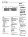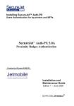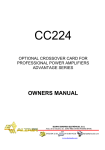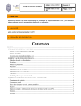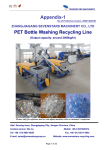
1
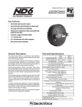
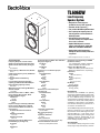
TL606DW Low-Frequency Speaker System • Designed for cinema stage use (behind the screen), THX® approved1 • Extended, 40-Hz response (f3) • Two premium DL15W long-throw woofers • Use as primary low-frequency source in two-way systems or as the subwoofer in multiway systems • Side-mounted connection panel facilitates hookup when depth behind the screen is restricted • Optional XEQ-504 passive crossover replaces connection panel—works with DH1A driver on HP940 or HP9040 horn • Optional HS6 or HS7 hanging kits— through-the-box steel tubes provide safe suspension ______________ 1. THX® is a registered trademark of Lucasfilm Ltd. SPECIFICATIONS Frequency Response, 10 Feet on Axis, Swept One-Third-Octave Pink Noise, HalfSpace Anechoic Environment (see Figure 1): 40-3,500 Hz Low-Frequency 3-dB-Down Point, Normal: 40 Hz Usable Low-Frequency Limit (10-dB-down point), Normal: 30 Hz Half-Space Reference Efficiency: 5.8% Long-Term Average Power Handling Capacity per EIA Standard RS-426A (see Power Handling Capacity section): 800 watts Maximum Long-Term Average Mid-Baud Acoustic Output: 11.6 watts Sound Pressure Level at 1 Meter, 1 Watt Input, Anechoic Environment, BandLimited Pink-Noise Signal, 100-800 Hz: 100 dB 40-125 Hz: 96 dB Dispersion Angle Included by 6-dB-Down Points on Polar Responses, Indicated One-Third-Octave Bands of Pink Noise (see Figure 3), 40-125 Hz Horizontal and Vertical: 360° 400-800 Hz Horizontal: 110° ±12° 400-800 Hz Vertical: 46° ±13° Directivity Factor Rθ (Q), Median Over Indicated Range (see Figure 4), 40-125 Hz: 1.0 400-800 Hz: 5.7 Directivity Index Di, Median Over Indicated Range (see Figure 4), 40-125 Hz: 0.0 dB 400-800 Hz: 7.5 dB Distortion, 0.1 Full Power Input (see Figure 6), Second Harmonic, 100 Hz: 0.45% 500 Hz: 0.28% Third Harmonic, 100 Hz: 0.14% 500 Hz: 0.89% Distortion, 0.01 Full Power Input (see Figure 5), Second Harmonic, 100 Hz: 0.16% 500 Hz: 0.1% Third Harmonic, 100 Hz: 0.16% 500 Hz: 0.5% Transducer Complement: Two DL15Ws Box Tuning Frequency: 40 Hz Impedance, Minimum: 4 ohms Input Connections: Screw terminals (#8-32) on barrier strip Enclosure Materials and Finish: Black, vinyl-clad particle board Suspension (see Suspending TL606DW Enclosures section): Two independently certified suspension kits are available, the HS6 and HS7 Optional Horn Mounting Kits: HMK-1 and HMK-2 (can be used with the MP940 and HP9040 horns, respectively) Dimensions, Height: 100.3 cm (39.5 in.) Width: 57.2 cm (22.5 in.) Depth: 44.7 cm (17.6 in.) Net Weight: 49.0 kg (108 lb) Shipping Weight: 54.4 kg (120 lb) DESCRIPTION The Electro-Voice TL606DW is an optimally vented, direct-radiator speaker system for highoutput reproduction of low frequencies to 40 Hz. The TL606DWs design is based on the vented-enclosure modeling technique of A.N. Thiele and R.H. Small, which makes possible a combination of high efficiency, low distortion, and extended low-frequency performance in an enclosure of moderate size. The TL606DW employs dual DL15W very-lowfrequency reproducers in a 9-cubic-foot (255 liter) enclosure. The DL15Ws high linear coneexcursion ability (Xmax = 0.22 inches, zero to peak) and 400-watt long-term average power capacity contribute substantially to the TL606DWs high acoustic output ability (see Power Handling Capacity section). APPLICATIONS The TL606DW is ideally configured for a wide variety of high-output, low-frequency reinforce- FIGURE 1 Axial Frequency Response (4 volts/10 feet) FIGURE 2 TL606DW One-Third-Octave Polar Responses (anechoic environment) FIGURE 3 TL606DW Beamwidth vs Frequency Whole Space (anechoic) FIGURE 4 TL606DW Directivity vs Frequency Whole Space (anechoic) FIGURE 5 TL606DW Harmonic Distortion, 0.01 Rated Power Input (8 watts), 10 Feet on Axis FIGURE 6 TL606DW Harmonic Distortion, 0.1 Rated Power Input (80 watts), 10 Feet on Axis FIGURE 7 Vertical and Horizontal Mounting Methods for the TL606DW Using the HS6 and HS7 Suspension Kits ment applications in permanently installed sound systems. Typical venues include cinemas, auditoriums, theaters, performing arts centers, night clubs and concert halls. The TL606DW is designed to serve as the primary low-frequency section in extended-response two-way systems with excellent bass performance to 40 Hz and controlled dispersion to 800 Hza typical crossover frequency of twoway systems. When used with the dedicated XEQ-504 crossover/equalizer, the TL606DW can be combined with appropriate ElectroVoice TransPlanarTM horns and DH series drivers to form a passive two-way system of unprecedented wide-range response and linearity. However, to extract the maximum performance from the TL606DW, a multiamp configuration using the XEQ-2 or XEQ-3 crossover/equalizer units is recommended so that full rated power may be applied to the lowfrequency system. With a half-power point of 40 Hz, the TL606DW can also serve as the subwoofer component in large, multiway systems. FREQUENCY RESPONSE The TL606DW frequency response was measured in an anechoic environment at 10 feet on axis with swept one-third-octave pink noise. The frequency response curve for the TL606DW are shown in Figure 1. DIRECTIVITY The TL606DW directional characteristics were measured by running a set of polar-response curves in EVs large, anechoic chamber. The test signal was one-third-octave pseudo-random pink noise centered at the frequencies indicated in Figure 2. The curves show horizontal (side-to-side) dispersion when the enclosures long axis is vertical. The vertical (up-and-down) polar responses are also shown. Additional typical information is provided in Figure 3 which shows 6-dB-down beamwidth versus frequency. Figure 4 shows the directivity factor and directivity index versus frequency. DISTORTION Following AES (Audio Engineering Society) recommended practice, plots of second- and third-order harmonic distortion for 0.1 rated input power are shown in Figure 6. Figure 5 shows distortion at 0.01 rated input power. POWER HANDLING CAPACITY To our knowledge, Electro-Voice was the first U.S. manufacturer to develop and publish a power test closely related to real-life conditions. First, we use a random noise input signal because it contains many frequencies simultaneously, just like real voice or instrument program. Second, our signal contains more energy at extremely high and low frequencies than typical actual program, adding an extra measure of reliability. Third, the test signal includes not only the overall long-term average or continuous levelwhich our ears interpret as loudnessbut also short-duration peaks which are many times higher than the average, just like actual program. The longterm average level stresses the speaker thermally (heat). The instantaneous peaks test mechanical reliability (cone and diaphragm excursion). Note that the sine-wave test sig- nals sometimes used have a much less demanding peak value relative to their average level. In actual use, long-term average levels exist from several seconds on up, but we apply the long-term average for several hours, adding another extra measure of reliability. Specifically, the TL606DW is designed to withstand the power test described in EIA Standard RS-426A. The EIA test spectrum is applied for eight hours. To obtain the spectrum, the output of a white noise generator (white noise is a particular type of random noise with equal energy per bandwidth in Hz) is fed to a shaping filter with 6-dB-per-octave slopes below 40 Hz and above 318 Hz. When measured with the usual constant-percentage analyzer (one-thirdoctave), this shaping filter produces a spectrum whose 3-dB-down points are at 100 Hz and 1,200 Hz with a 3-dB-per-octave slope above 1,200 Hz. This shaped signal is sent to the power amplifier with the continuous power set at 800 watts into the 3.5 ohms EIA equivalent impedance for the TL606DW (52.9 volts true rms). Amplifier clipping sets instantaneous peaks at 6 dB above the continuous power, or 3,200 watts peak (105 volts peak). This procedure provides a rigorous test of both thermal and mechanical failure modes. SUBPASSBAND SPEAKER PROTECTION Below the enclosure tuning frequency, cone excursion increases rapidly. Since acoustic output is also failing rapidly, there is no utility in driving the system with signals much below the tuning frequency. While such signals may be in the program material, they are often extraneoussuch as from record-surface irregularities (strong 5- to 25-Hz components) or a dropped microphone. The DL15W very-lowfrequency reproducer is ruggedly designed and has a high maximum excursion before damage (±0.5 inch). However, high-output subwoofer systems such as the TL606DW should be protected by a high-pass filter with a 3-dBdown corner frequency of about 0.8 the enclosure tuning frequency. Below the corner frequency, a roll-off of 12-dB-per-octave is usually sufficient. Without protection, subpassband signals may bottom the DL15Ws. Damage will probably result, especially after repeated occurrences. Even if bottoming does not occur, the subpassband signals waste amplifier power and modulate (distort) the frequencies which are within the TL606DWs operating range. Much woofer distortion or muddy bass can be attributed to lack of subpassband protection. The Electro-Voice EX-24, XEQ-2 and XEQ-3 electronic crossover/equalizers provide subpassband protection. The 3-dB-down points are 30 Hz (EX-24 and XEQ-2) and 16 Hz or 32 Hz (XEQ-3). Other high-pass filters are available, and onethird-octave equalizers can also be effective at providing the required protection. USE IN MULTIPLES TL606DWs may be used in multiples to increase acoustic output. In the following discus- sion, it is assumed that all speaker cones are operating in unison (in phase) when a common signal is applied. A 6-dB increase in maximum acoustic output results when two speakers are located side by side. For operation at very low frequencies, the woofer cones mutually couple, acting as one speaker with cone area and power-handling capacity twice that of a single speaker. The doubling of cone area doubles efficiency, providing a 3-dB increase in sound pressure level. The second 3 dB comes from the doubling of power capacity. Mutual coupling occurs when the frequency is such that the center-to-center distance between the two speaker cones is less than about one-quarter wavelength. For a given center-tocenter distance, the highest frequency at which mutual coupling will occur can be calculated from the following formula: 3,000 f = , Dmax where Dmax is the distance in inches and f is frequency in Hz. When Dmax is greater than one-quarter wavelength, as would occur if two TL606DWs were widely spaced, the level increase tends to be limited to the 3-dB power-handling increase. More than two TL606DWs can be used for increased output. In general, maximum acoustic power output ability increases as the square of the number of mutually coupled cones. For example, four cones would provide 42 or 16 times the power output of a single cone, an increase of 12 dB (10 log10 16 = 12 dB). Note that the associated increased efficiency (2.9% X 4 = 12%) approaches that of a fully horn-loaded design, but in a much smaller enclosure. SYSTEM POSITIONING Subwoofer systems such as the TL606DW are often located on the floor. This is both convenient and can provide a desired high acoustic impact when the speakers are, for example, placed near the periphery of a dance floor. In other installations, such as a theater or auditorium, the audible location of a subwoofer operating at a sufficiently low crossover frequency (below about 125 Hz) will not be particularly evident. The other system elements operating above the subwoofer range can be positioned for the desired locational cues and uniform audience coverage. Floor location provides the acoustic half-space environment associated with the 5.8% system efficiency noted in the Specifications section. Location at a floor-wall junction (acoustic quarter space) doubles efficiency (a 3-dB increase in sound pressure level) and tends to promote the full excitation of more room modes, or standing waves, important in achieving maximum overall bass output in the room. Corner placement (acoustic eighth space) doubles efficiency again and guarantees excitation of all room modes. (Such placement for maximum efficiency and room-mode excitation is not necessary and may not be desirable or possible for a variety of reasons, including aesthetics and building design.) The TL606DW can also be successfully operated away from any nearby acoustic boundaries, particularly when multiple systems are used for increased output ability (see Use in Multiples section). SUSPENDING TL606DW ENCLOSURES The TL606DW is designed for typical cinema stage (behind-the-screen) applications where low-frequency systems are mounted on platforms, behind the screen and some distance above the stage floor. The TL606DW is not designed to be self-suspended, and if suspended, must be supported and hung in a way which does not depand on the structure of the TL606DW itself for support. The HS6 and HS7 kits allow the TL606DW to be hung safely in a variety of orientations. The combination of the correct HS kits and TL606DW enclosure has been certified by an independent structural engineer to be safe and secure. Each HS kit consists of a steel tube, two brackets, two eyebolts and the necessary fasteners. The installer must assemble the HS kit by first drilling two holes into the TL606DW enclosure, in predefined positions, and then screwing the brackets onto the steel tube, which passes through the enclosure. An eyebolt is inserted in the T-nut in the rear panel of the enclosure to provide a pull up to aim the enclosure. Full instructions and hole locations are included with each cabinet and HS kit. A TL606DW requires a single HS6 to suspend it horizontally, or a single HS7 to suspend it vertically. Electro-Voice recommends that only one TL606DW be suspended at one time in this manner. Vertical is defined as having the long side vertical. Full attention must be given to the instructions and limitations in the HS kit instruction sheet. ACCESSORIES FOR SPECIAL SYSTEMS The TL606DW was designed to be used with Electro-Voice TransPlanarTM horns, DH series compression drivers and accessories to form passive, 500 Hz crossover systems that may be easily and quickly assembled and installed. A 500-Hz passive crossover, the XEQ-504, directly replaces the TL606DWs input panel. Mounting kits, the HMK-1 and HMK-2, provide the necessary hardware and accessories to mount the HP940/DH1A and HP9040/DH1A horn/driver combinations, respectively, to the TL606DW box. Steel threaded inserts are provided on the top panel of the box to accommo- date mounting kits for both horn combinations. ARCHITECTS AND ENGINEERS SPECIFICATIONS The loudspeaker system shall consist of two 380-mm (15-in.) very-low-frequency reproducers installed in a vented enclosure. The frame of the reproducer shall be manufactured of cast aluminum, and its magnetic assembly shall utilize a ferrite magnet. In addition, an aluminum ring encircling both the voice coil and pole piece shall act to reduce flux modulation. A second aluminum ring mounted to the top of the pole piece shall act as a control on drive inductance and provide a heat-transfer path from the top of the voice coil. The inner surface of the top plate shall be coated with PROTEFTM, a Teflon®-based coating used for prevention of damage to the voice coil.1 Performance specifications of a typical production unit shall be as follows: measured sensitivity (SPL at 1 m on axis with 1 W input, swept 100-800 Hz) shall be at least 100 dB SPL; usable frequency range shall extend from 30 Hz to 3,500 Hz; nominal impedance shall be 4 ohms; rated power handling capacity shall be at least 800 watts, conforming to EIA standard RS-426A. The enclosure shall be solidly constructed of 19-mm (3/4-in.) stock with all joints tightly fitted and glued. Overall dimensions shall be no greater than 100.3 cm (39.5 in.) high by 57.2 cm (22.5 in.) wide by 44.7 cm (17.6 in.) deep. Finish shall be black vinyl with leatherette pattern. An independently certified suspension kit shall be available to suspend the TL606DW horizontally (model HS6) or vertically (model HS7). Internal 1/4-20 threaded fasteners provide a method of mounting high-frequency devices to the system. The system shall be the Electro-Voice TL606DW. WARRANTY (Limited) Electro-Voice products are guaranteed against malfunction due to defects in materials or workmanship for a specified period, as noted in the individual product-line statement(s) below, or in the individual product data sheet or owners manual, beginning with the date of original purchase. If such malfunction occurs during the specified period, the product will be repaired or replaced (at our option) without charge. The product will be returned to the customer prepaid. Exclusions and Limitations: The ____________________ 1. Telflon® is a registered trademark of DuPont. ELECTRO-VOICE MANUFACTURING PLANTS AT BUCHANAN, MI © Electro-Voice, Inc. 1997 Litho in U.S.A. Limited Warranty does not apply to: (a) exterior finish or appearance; (b) certain specific items described in the individual product-line statement(s) below, or in the individual product data sheet or owners manual; (c) malfunction resulting from use or operation of the product other than as specified in the product data sheet or owners manual; (d) malfunction resulting from misuse or abuse of the product; or (e) malfunction occurring at any time after repairs have been made to the product by anyone other than Electro-Voice or any of its authorized service representatives. Obtaining Warranty Service: To obtain warranty service, a customer must deliver the product, prepaid, to Electro-Voice or any of its authorized service representatives together with proof of purchase of the product in the form of a bill of sale or receipted invoice. A list of authorized service representatives is available from Electro-Voice at 600 Cecil Street, Buchanan, MI 49107 (616/ 695-6831) and/or Electro-Voice West, at 8234 Doe Avenue, Visalia, CA 93291 (209/651-7777). Incidental and Consequential Damages Excluded: Product repair or replacement and return to the customer are the only remedies provided to the customer. Electro-Voice shall not be liable for any incidental or consequential damages including, without limitation, injury to persons or property or loss of use. Some states do not allow the exclusion or limitation of incidental or consequential damages so the above limitation or exclusion may not apply to you. Other Rights: This warranty gives you specific legal rights, and you may also have other rights which vary from state to state. Electro-Voice Speakers and Speaker Systems are guaranteed against malfunction due to defects in materials or workmanship for a period of five (5) years from the date of original purchase. The Limited Warranty does not apply to burned voice coils or malfunctions such as cone and/or coil damage resulting from improperly designed enclosures. Electro-Voice active electronics associated with the speaker systems are guaranteed for three (3) years from the date of original purchase. Additional details are included in the Uniform Limited Warranty statement. Service and repair address for this product: Electro-Voice, Inc., 600 Cecil Street, Buchanan, Michigan 49107. Specifications subject to change without notice. 600 Cecil Street, Buchanan, Michigan 49107 NEWPORT, TN SEVIERVILLE, TN OKLAHOMA CITY, OK GANANOQUE, ONT. Part Number 534268 9711