1
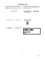
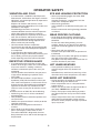
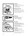
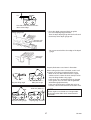
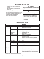
OPERATOR’S MANUAL
CHAIN SAW
CS-440
WARNING
Read the instructions carefully and follow the rules for safe
operation.
Failure to do so could result in serious injury.
ECHO POWER EQUIPMENT (CANADA)
501 Newbold Street, London, Ontario Canada N6E 1K4
X750-006 21 4
X750 319-510 4
RULES FOR SAFE OPERATION
1. Fatigue causes carelessness. Be more
cautious before rest periods and before
the end of your shift.
11. Do not attempt a pruning or liming
operation in a standing tree unless
specifically trained to do so.
2. Personal protective clothing required by
your safety organizations, government
regulations, or your employer should be
used; otherwise, sung fitting clothing,
protective eyewear, safety footwear and
hand, leg and hearing protection should
be worn.
Note: Personal protective clothing
should meet the requirements
of applicable Standards.
3. Before fueling, servicing or transporting
your chain saw switch off the engine. To
help prevent fire, restart your chain saw
at least 3 m from the fueling area.
12. Guard against kickback. Kickback is the
upward motion of the guide bar, which
occurs when the saw chain, at the nose
of the guide bar, contact an object.
Kickback can lead to dangerous loss of
the chain saw.
TO AVOID KICKBACK:
(a) Contact of the guide bar tip with any
object should be avoided.
(b) Tip contact may cause the guide bar
to move suddenly upward and
backward which may cause serious
injury.
(c) Always use two hands when
operating the chain saw.
(d) Use a firm grip, thumbs and fingers
encircling the handles.
(e) Don’t overreach.
(f) Avoid cutting above shoulder height.
(g) Follow the manufacture’s instructions
for sharpening and maintenance of
the saw chain.
4. When using a chain saw a fire
extinguisher should be available.
5. When felling, keep at least 2 tree
lengths between yourself and your
fellow workers.
6. Plan your work; assure yourself of an
obstacle-free work area and, in the case
of felling, of an escape path from the
falling tree.
13. When boring with the chain saw, the
initial cut should be introduced with the
lower part of the nose (tip) until the hole
is sufficiently large so as to introduce the
entire nose (tip) of the guide bar. This
technique should reduce the danger of
kickback.
7. Follow instructions in your operator’s
manual for starting the chain saw and
control the chain saw with a firm grip on
both handles when it is in operation.
Keep handles dry, clean and free of oil.
A chain saw should never be carried
with the engine running.
14. A chain saw is intended for two-handed
use. Serious injury to the operator,
helpers and/or bystanders may result
from one-handed operation.
8. When transporting your chain saw, use
the appropriate transportation covers
that should be available for the guide
bar and saw chain.
CAUTION
A. Allow your chain saw to cool before
refueling, and do not smoke while
refueling.
9. Never operate a chain saw that is
damaged, improperly adjusted, or is not
completely and securely assembled. Be
sure that the saw chain stops moving
when the throttle control trigger is
released. Never adjust the guide bar or
saw chain when the engine operating.
B. Do not allow other persons or animals
close to running chain saw or close to
where a tree is being felled.
C. Use extreme caution when cutting small
size brush and saplings because
slender material may catch the saw
chain and be whipped toward you.
10. Beware of carbon monoxide poisoning.
Operate the chain saw in well-ventilated
areas only.
Copyright © 2003
CS-440
D. When cutting a limb that is under
tension is alert for spring-back.
All Rights Reserved.
2
CONTENTS
RULES FOR SAFE OPERATION .............................................................................
SYMBOLS AND SIGNS ...........................................................................................
PACKING LIST .........................................................................................................
NOMENCLATURE OF PARTS .................................................................................
OPERATOR SAFETY ...............................................................................................
CORRECT USE OF CHAIN BRAKE ........................................................................
PREPARATION FOR USE .......................................................................................
FUEL AND LUBRICANT ..........................................................................................
OPERATION ............................................................................................................
CUTTING INSTRUCTION ........................................................................................
CHAIN AND GUIDE BAR COMBINATION ..............................................................
MAINTENANCE AND CARE ....................................................................................
SETTING THE SAW CHAIN.....................................................................................
TROUBLESHOOTING .............................................................................................
STORAGE AFTER USE...........................................................................................
TECHNICAL DATA ...................................................................................................
2
3
5
6
8
9
10
12
13
16
21
22
26
28
29
29
This spark ignition system complies with Canadian ICES-002.
This chain saw is designed for cutting wood or wood products. Do not cut solid metal,
sheet metal, plastic or any non-wood materials.
Specifications, descriptions and illustrative material in this literature are as accurate as
known at the time of publication, but are subject to change without notice.
Illustrations may include optional equipment and accessories, and may not include all
standard equipment.
SYMBOLS AND SIGNS
CIRCLE AND SLASH SYMBOL
DANGER
This symbol means the specific action
shown is prohibited. Ignoring these
prohibitions can result in serious or
fatal injury.
The safety alert symbol accompanied by the
word “DANGER” calls attention to an act or
condition which WILL lead to serious
personal injury or death if not avoided.
NOTE
WARNING
This enclosed message provides tips for use,
care and maintenance of the unit.
The safety alert symbol accompanied by the
word “WARNING” calls attention to an act or
condition which CAN lead to serious
personal injury or death if not avoided.
IMPORTANT
The enclosed message provides information
necessary for the protection of the unit.
CAUTION
The safety alert symbol accompanied by the
word “CAUTION” calls attention to an act or
condition which may lead to minor or
moderate personal injury if not avoided.
3
CS-440
SYMBOL FORM
Symbol form/shape Symbol description/application Symbol form/shape Symbol description/application
STOP
Carefully read the operator’s
manual
Chain oil fill
Wear eyes, ears and head
protection
Chain oil pump
Chain brake operation
Chain oiler adjustment
Emergency stop
Carburetor adjustment
- Low speed mixture
Choke control “Cold Start”
position (choke closed)
Carburetor adjustment
- High speed mixture
Oil and gasoline mixture
Carburetor adjustment
- Idle speed
DECALS
Part Number X503-005610
Part Number 890176-39431
CS-440
CAUTION/ATTENTION
Hearing protectors meeting the requirements
of CSA Standard Z94.2 should be worn.
CAUTION: For safe operation follow all
safety precautions and instructions in
operator’s Manual. (Replacement manuals
are available from your ECHO dealer.)
Hold chain saw firmly with both hands.
Les protecteurs auditifs pouvant être porter
doivent recontrer les normes CSA Standard
Z94.2.
Part Number X524-001171
Part Number 890324-39630
REPLACEMENT BAR AND CHAIN
PEMPLACEMENT DU GUIDE ET DE LA CHAÎNE
ATTENTION
Pour un travail en sécurité, respectez toutes
les règles de sécurité et les indications du
manuel d’utilisation. (Le manuel d’utilisation
est disponibile chez votre agent ECHO.) Tenez
fermement la tronçonneuse des deux mains.
GUIDE BAR P/NO.
CHAIN TYPE
CKA
GUIDE PIECE NO.
TYPE DE CHAÎNE
16” 16A0AD3366
OREGON 33SL 66 11.5
18” 18A0AD3372
OREGON 33SL 72 30.6
20” 20A0AD3378
OREGON 33SL 78 25.0
CKA means Computed Kickback Angle.
CKA Signifie angle de rebondissement calculé.
Note; There may be other replacement
components for achieving kickback
p r o t e c t i o n . Fo r d e t a i l s , p l e a s e r e fe r
to the chain and bar combination
sheet shown in the operator’s manual.
REMARQUE; Il y peut y avoir d’autres
composantes de remplacement qui protègent
en cas de rebondissement. Pour plus de
détails, se référer à la feuille sur les
combinaisons de guide et de chaîne du
manuel de l’utilisateur.
Part Number X505-000450
TO AVOID KICKBACK
1. Contact of the guide bar tip with any
object should be avoided.
2. Tip contact may cause the guide bar to
move suddenly upward and backward
which may cause serious injury.
3. Always use two hands when operating
the chain saw.
Part Number X505-002050
Part Number X505-000460
WARNING
Chain brake must be unlocked before removing or installing clutch
cover. Improper cover installation can result in serious injury and
cause severe damage to saw.
La frein du chaînes doit être désengagé avant d’enlever ou installer
la couverture d’embrayage. La couverture installée inexactement
peut avoir conséquence d’blessures serieuseset endommager la scie.
POUR ÉVITER LES REBONDISSEMENTS
1. Éviter tout contact entre le nez du
guide-chaîne et un objet quelconque.
2. Tout contact du nez peut provoquer un
mouvement brusque vers le haut ou vers
le bas et entraîner de graves blessures.
3. Toujours employer lex deux mains
pour opérer la scie à chaîne.
CS-440
Locate this safety decal on your unit. The complete
unit illustration found in the “NOMENCLATURE OF
PARTS” section will help you locate them.
Make sure the decal is legible and that you
understand and follow the instructions on it. If a
decal cannot be read, a new one can be ordered
from your ECHO dealer.
4
PACKING LIST
The ECHO product you purchased has been
factory pre-assembled for your convenience. Due to
packaging restrictions, guide bar and saw chain
installation and other assembly may be necessary.
After opening the carton, check for damage.
Immediately notify your retailer or ECHO dealer of
damaged or missing parts. Use the packing list to
check for missing parts.
13 x 19 mmT-wrench,
4 mm Hexagonal Wrench,
Small screwdriver
ECHO CHAIN SAW
Instruction manual
Safety manual
Limited warranty
statement
Warranty registration
card
Spiked bumper,
Bolts 5 × 12 mm
ECHO Power Blend™
2-stroke oil sample
5
CS-440
CS-440
6
NOMENCLATURE OF PARTS
1. Operator’s manual - Included with unit.
Read before operation and keep for future
reference to learn proper, safe operating
techniques.
11. Bar tip guard - Anti-kickback device attached
on the bar nose.
12. Saw chain - Chain, serving as a cutting tool.
13. Spiked bumper - Device, fitted in front of the
guide bar mounting point, acting as a pivot
when in contact with a tree or log.
2. Safety manual - Describe operating and safety
instructions for this chain saw.
3. Front hand guard - Guard between the front
handle and the saw chain for protecting the
hand from injuries and aiding in control of the
chain saw if the hand slips off the handle.
This guard is used to lock the chain brake
which is to stop the saw chain rotation.
14. Front handle (for the left hand) - Support
handle located at the front of the engine
housing.
15. Oil tank cap - For closing the oil tank.
4. Cylinder cover - The cooling airflow grill. It
covers the cylinder, spark plug, silencer and
air cleaner.
16. Starter handle - Pull handle slowly until starter
engages then quickly and firmly. When
engine starts, return handle slowly.
DO NOT let handle snap back or damage to
unit will occur.
5. Rear handle (for the right hand) - Support
handle located towards the rear of the
engine housing.
17. Fuel tank cap - For closing the fuel tank.
18. Throttle latch - Device for temporality setting
the throttle in a partially open position to aid
starting.
6. Choke control knob - Device for enriching the
fuel/air mixture in the carburetor to aid cold
starting.
19. Throttle trigger - Device activated by the
operator’s finger, for controlling the engine
speed.
7. Rear hand guard - Extension on the lower part
of the rear handle for protecting the hand
from the chain if it breaks or degrooves.
20. Throttle trigger lockout - A safety lever which
must be depressed before the throttle trigger
can be activated in order to prevent the
accidental operation of the throttle trigger.
8. Clutch cover - Protective cover to the guide
bar, saw chain, clutch and sprocket when the
chain saw is in use.
21. Ignition switch - Device for connecting and
disconnecting the ignition system and thus
allowing the engine to be started or stopped.
9. Chain catcher - A projection designed to
reduce the risk of the operator’s right hand
from being hit by a chain which has broken
or derailed from the guide bar during cutting.
10. Guide bar - The part that supports and guides
the saw chain.
7
CS-440
OPERATOR SAFETY
VIBRATION AND COLD
EYE AND HEARING PROTECTION
• It is believed that a condition called Raynaud’s
Phenomenon, which affects the fingers of certain
individuals, may be brought about by exposure to
vibration and cold.
Exposure to vibration and cold may cause
tingling and burning followed by loss of color and
numbness in the fingers.
The following precautions are strongly
recommended because the minimum exposure
which might trigger the ailment is unknown.
• Keep your body warm, especially the head and
neck, feet and ankles and hands and wrists.
• Maintain good blood circulation by performing
vigorous arm exercises during frequent work
breaks and also by not smoking.
• Limit the number of hours of operation.
Try to fill each day with jobs where operating the
chain saw, or other hand-held power equipment
is not required.
• If you experience discomfort redness and
swelling of the fingers, followed by whitening and
loss of feeling, consult your physician before
further exposing yourself to cold and vibration.
• Wear eye protection goggles that meet ANSI
Z 87.1 requirements.
Goggles meeting the requirements have the
mark “Z 87” stamped on them.
• Wear hearing protection.
If this guideline is not followed, hearing loss can
occur.
ECHO recommends wearing hearing protection
at all times.
WEAR PROPER CLOTHING
• Snug fitting durable clothing should be worn.
Pants should have long legs, DO NOT WEAR
SHORTS.
Do not wear loose fitting clothing, scarves,
neckties, jewelry or any item that may become
tangled in surrounding growth or the chain saw
itself.
• Wear shoes with non-skid soles.
DO NOT wear open toed shoes or operate unit
barefooted.
• Wear no-slip, heavy duty work gloves to improve
your grip on the chain saw handles.
The gloves also help reduce the transmission of
machine vibration to your hands.
REPETITIVE STRESS INJURY
• It is believed that over-using the muscles and
tendons of the finger, hands, arms and shoulders
may cause soreness, swelling, numbness,
weakness and extreme pain to the areas just
mentioned.
Certain repetitive hand activities may put you at
a high risk for developing a repetitive stress
injury (RSI).
• An extreme RSI condition is Carpal Tunnel
Syndrome (CTS) which could occur when your
wrist swells and squeezes a vital nerve that runs
through the area. Some believe that prolonged
exposure to vibration may contribute to CTS.
CTS can cause severe pain for months or even
years.
To reduce the risk of RSI/CTS, do the following:
• Avoid using your wrist in a bent, extended or
twisted position.
• Take periodic breaks to minimize repetition and
rest your hands.
• Reduce the speed and force in which you do the
repetitive movement.
• Do exercises to strengthen hand and arm
muscles.
• See a doctor if you feel tingling, numbness or
pain in your fingers, hands, wrists or arms.
The sooner RSI/CTS is diagnosed, the more
likely permanent nerve and muscle damage can
be prevented.
CS-440
HOT HUMID WEATHER
• Heavy protective clothing can increase
operator fatigue which may lead to heat
stroke.
Schedule heavy work for early morning, or late
afternoon hours when temperatures are cooler.
AVOID HOT SURFACES
• During operation, the muffler or catalytic muffler
and surrounding cover become hot.
• Never suspend the saw on a lanyard with the
engine running.
• Always use the saw from the right-hand side of
your body - NEVER from the left side.
• Always wear proper safety clothing to protect
your lower body from sharp saw chain and hot
muffler.
• Always keep exhaust area clear of flammable
debris during transportation or when storing,
otherwise serious property damage or personal
injury may result.
8
9
CS-440
PREPARATION FOR USE
WARNING
Saw Chain is sharp! Always wear gloves
when handling assembly, otherwise serious
personal injury may result.
KICK GUARD® TO BAR
INSTRUCTIONS
Tools Needed: Two 11 mm Wrenches.
For saws with Kick Guard® P/N 2893201 and
Symmetrical Low-Kick type (Double Guard)
guide bars.
Bolt (A)
Dimple (D)
1. Install bolt (A) in rear hole (B) of Kick Guard®
and through front hole (C) in guide bar.
Kick Guard®
2. IMPORTANT: Dimple (D) in Kick Guard® must
engage recess (E) in guide bar.
Rear hole (B)
Recess (E)
Front hole (C)
3. Tighten nut (F) and bolt (A) using 11 mm
wrenches until snug. Make certain Kick Guard®
is flush against guide bar.
4. Tighten nut (F) 1/8 additional turn.
Nut (F)
Guide bar
5. Check to make certain Kick Guard® is tight on
guide bar.
GUIDE BAR AND SAW CHAIN
INSTALLATION/REMOVAL
NOTE
Brake lever
(Front hand guard)
Move the chain brake lever (Front hand guard)
fully rearward to remove or install the clutch
cover to the chain saw.
1. Remove spark plug lead. (See page 24)
2. Remove two clutch cover nuts and remove clutch
cover.
3. Remove bar and saw chain if necessary. See
“Maintenance and Care” section for guide bar/
saw chain maintenance procedures.
4. For initial setup, install the spiked bumper on the
front of machine with two 5 × 12 mm bolts.
Clutch cover
Two nuts
CS-440
10
5. Mount guide bar on studs and slide toward clutch
to make saw chain installation easier. Install
chain with cutters on top of guide bar facing
foward.
6. Slide bar forward and ensure tensioner pin fits
into lower adjustment hole.
7. Unlock the chain brake, and install the clutch
cover over the guide bar studs. Ensure brake
band is positioned around clutch drum, and tab
at rear of clutch cover fits underneath tab on
engine cover. Tighten clutch cover nuts finger
tight.
8. Turn saw over and check brake band for correct
position on clutch drum. If brake band is not in
place around drum, remove cover, make sure
brake is unlocked, and reinstall. Tighten clutch
cover nuts finger tight.
WARNING
Improper clutch cover assembly can result in
serious injury, and will cause severe saw
damage if unit is started. Never start or
operate saw if brake band is not in place on
clutch drum. Always check chain brake
operation after replacing cover. Do not use
saw if chain brake does not function
properly.
Unlock chain brake
ADJUSTING CHAIN TENSION
IMPORTANT
Always loosen clutch cover nuts before turning
the chain tension adjuster, otherwise the clutch
cover and tensioner will be damaged.
1. Remove spark plug lead. (See page 24)
2. Loosen two clutch cover nuts, if necessary.
3. Hold the bar nose up, and turn the adjuster
screw clockwise until chain fits snugly against
underside of the bar.
4. Tighten both nuts with the bar nose held up.
Proper tension
5. Pull the chain around the bar by hand. Loosen
the adjustment if you feel tight spots.
Improper tension
6. When chain is properly tensioned, tighten clutch
cover nuts securely - 20 to 23 N·m (200 to 230
kgf·cm).
7. Keep chain properly tensioned at all times.
11
CS-440
FUEL AND LUBRICANT
Fuel Mix Chart 50 : 1
FUEL STATEMENT
Gasoline
L
4
8
20
GASOLINE - Use 89 Octane [(R+M)/2] (mid grade
or higher) gasoline or gasohol known to be good
quality.
Gasohol may contain up to 10 % Ethyl (grain)
alcohol or 15 % MTBE (methyl teriary-butyl ether).
Gasohol containing methyl (wood) alcohol is NOT
approved.
Oil
mL
80
160
400
IMPORTANT
TWO-STROKE OIL - A two-stroke engine oil
meeting ISO-L-EGD (ISO/CD 13738) and JASO
FC Standards must be used. ECHO brand premium
Power Blend™ Universal 2-Stroke Oil meets these
standards. Engine problems due to inadequate
lubrication caused by failure to use an ISO-L-EGD
and JASO FC certified oil, such as ECHO premium
Power Blend™, will void the two-stroke engine
warranty. (Emission related parts only are covered
for two years, regardless of two-stroke oil used, per
the statement listed in the Emission Defect
Warranty Explanation.)
• ECHO premium Power Blend™ Universal 2Stroke Oil may be mixed at 50 : 1 ratio for
application in all ECHO engines sold in the past
regardless of ratio specified in those manuals.
• Use of unmixed, improperly mixed, or fuel older
than 90 days, (stale fuel), may cause hard
starting, poor performance, or severe engine
damage and void the product warranty. Read
and follow instructions in the Storage section of
this manual.
HANDLING FUEL
DANGER
MIXING INSTRUCTIONS 1. Fill an approved fuel container with half of the
required amount of gasoline.
2. Add the proper amount of two-stroke oil to
gasoline.
3. Close container and shake to mix oil with
gasoline.
4. Add remaining gasoline, close fuel container,
and remix.
Fuel is VERY flammable. Use extreme care
when mixing, storing or handling or serious
personal injury may result.
• Use an approved fuel container.
• DO NOT smoke near fuel.
• DO NOT allow flames or sparks near fuel.
• Fuel tanks/cans may be under pressure.
Always loosen fuel caps slowly allowing
pressure to equalize.
• NEVER refuel a unit when the engine is
HOT!
• NEVER refuel a unit with the engine
running.
• DO NOT fill fuel tanks indoors.
ALWAYS fill fuel tanks outdoors over bare
ground.
• Securely tighten fuel cap after refueling.
• Inspect for fuel leakage.
If fuel leakage is found, do not start or
operate unit until leakage is repaired.
• Move at least 3 m from refueling location
before starting the engine.
IMPORTANT
• Spilled fuel is a leading cause of hydrocarbon
emissions. Some states may require the use of
automatic fuel shut-off containers to reduce fuel
spillage.
• Stored fuel ages.
Do not mix more fuel than you expect to use in
thirty (30) days, ninety (90) days when a fuel
stabilizer is added.
• Stored two-stroke fuel may separate. ALWAYS
shake fuel container thoroughly before each
use.
AFTER USE DO NOT store a unit with fuel in its tank. Leaks can
occur. Return unused fuel to an approved fuel
storage container.
STORAGE Fuel storage laws vary by locality. Contact your
local government for the laws affecting your area.
As a precaution, store fuel in an approved, airtight
container. Store in a well-ventilated, unoccupied
building, away from sparks and flames.
CS-440
12
13
CS-440
WHEN THE ENGINE IS HARD TO
START
Chain brake
CAUTION
Make sure the bar and chain are free from
any obstruction when starting the chain saw.
• Move chain brake lever fully forward to lock chain
brake before starting.
• Press throttle trigger lockout down while
grasping throttle trigger and push in throttle latch.
• Move ignition switch to “RUN” position.
• Securely hold the chain saw as shown and pull
starter handle.
• When engine starts, immediately squeeze
throttle trigger, to release throttle latch, and pull
front hand guard towards the operator
immediately. (Chain brake unlocked position)
Ignition switch
START/RUN
Throttle trigger lockout
PUSH
Throttle latch
Throttle trigger
CAUTION
1. When using throttle latch for starting, keep
the brake in lock position.
2. After starting the engine, squeeze throttle
trigger slightly to release throttle latch and
pull front hand guard towards the operator
immediately.
(Chain brake unlocked position)
3. Do not increase engine speed while chain
brake is locked.
4. Use the chain brake only in starting or in
emergencies.
Starter handle
Unlock chain brake
CAUTION
The chain will attempt to rotate when engine
is started with throttle latch engaged.
After engine starts, release throttle trigger to
idle engine, otherwise brake damage may
occur. Never use throttle latch for cutting.
Use it only when starting the engine.
WHEN THE ENGINE IS WARM
• Move chain brake lever fully forward to lock chain
brake before starting.
• Confirm there is fuel and chain oil in the tanks.
• Move ignition switch to “RUN” position.
• Securely hold the chain saw as shown and pull
starter handle.
• Choke may be used if necessary, but be sure to
push it back on first firing sound.
• After starting the engine, pull front hand guard
towards the operator immediately. (Chain brake
unlocked position)
Choke control knob
OPEN CHOKE
Unlock chain brake
CS-440
14
RUNNING
• When engine starts, keep idling for a few
minutes.
• Set the brake lever in the unlocked position
before starting to cut.
• Pull throttle trigger gradually and increase
revolution of the engine.
• The chain starts running when the engine
reaches to 3,800 r/min approximately.
• Confirm proper acceleration and lubrication of
chain and bar.
• Do not run the engine at high speed
unnecessarily.
• Be sure that saw chain stops moving when
throttle trigger is released.
STOPPING
• Release throttle trigger and move ignition switch
down to “STOP” position.
STOP
NOTE
If engine does not stop, pull choke control knob
out fully to stop engine.
Return the unit to your authorized ECHO dealer
to check and repair stop switch before starting
the engine again.
CHECKING CHAIN TENSION
• Chain tension should be checked frequently
during work and corrected as necessary.
• Tension the chain as tight as possible, but so it
can still be pulled easily along the bar by hand.
CAUTION
Do not operate with a loose chain.
CHAIN LUBRICATION TEST
Hold the chain just above a dry surface and open
the throttle to half speed for 30 seconds.
A thin line of “thrown” oil should be seen on the dry
surface.
15
CS-440
CUTTING INSTRUCTION
GENERAL
CAUTION
• Read the ECHO “CHAIN SAW SAFETY
MANUAL” included with your chain saw for
additional cutting and safety instructions.
• Wear suitable hearing protection such as
earmuffs or earplugs to protect against
objectionable or uncomfortable loud noises.
• Do not let the tip of the bar touch anything
while the engine is running.
At cutting speed the chain is moving at a
high rate of speed.
Should the tip contact a limb or log while
the chain is moving, the tip will be pushed
upward with considerable force.
This is known as kickback. Avoid it!
In all circumstances the operation of the chain saw
is a one-man job.
It is difficult at times to take care for your own
safety, so don’t assume the responsibility for a
helper as well.
After you have learned the basic techniques of
using the saw, your best aid will be your own good
common sense.
The accepted way to hold the saw is to stand to the
left of the saw with your left hand on the front
handlebar and your right hand on the rear handle
so you can operate the throttle trigger with your
right index finger.
Before attempting to fell a tree, cut some small logs
or limbs.
Become thoroughly familiar with the controls and
the responses of the saw.
Start the engine, see that it is running properly.
Squeeze the trigger to open the throttle wide open
and start the cut. If the chain is properly sharpened,
the cutting should be relatively effortless.
It is not necessary to press down hard to make the
saw cut.
Pushing the saw too hard will slow the engine and
cutting will actually be more difficult.
Some material may adversely affect the housings
of your chain saw.
(Example palm Tree Acid, fertilizer etc.)
To avoid housing deterioration, carefully remove all
packed sawdust around clutch and guide bar area
and wash with water. Coat metal parts with light oil.
Kickback
CS-440
16
FELLING THE TREE
A falling tree can seriously damage anything it may
hit - a car, a house, a fence, a power-line, or
another tree.
There are ways to make a tree fall where you want
it, so first decide where that is!
Before cutting, clear the area around the tree.
You will need good footing while working and you
should be able to work the saw without hitting any
obstacles.
Next, select a path of retreat.
When the tree begins to fall you should retreat
away from the direction of fall at a 45-degree angle
and at least 3 m from the trunk to avoid the trunk
kicking back over the stump.
3m
Retreat
Direction of fall
45°
45°
Retreat
Not this way
Begin the cut on the side to which the tree is to fall.
Cut a notch about 1/3 of the way into the tree.
The position of this notch is important since the
tree will try to fall “into” the notch.
The felling cut is made on the side opposite the
notch and at a level about 5 cm above the bottom
of the notch.
Do not try to cut through to the notch with the felling
cut.
The remaining wood between the notch cut and
felling cut about 5 cm will act as a hinge when the
tree falls, guiding it in the desired direction.
When the tree starts to fall, kill the engine, place
the saw on the ground and make your retreat
quickly.
Direction of fall
Hinge
5 cm
First cut
Felling cut
Notch
Second cut
5 cm
One-third tree diameter
To fell big trees with a diameter exceeding twice the
bar length, start the notching cuts from one side
and draw the saw through to the other side of the
notch.
Start the back cut on one side of the tree, pivoting
the saw through to form the desired hinge on that
side.
Then remove the saw for the second cut. Insert the
saw in the first cut, very carefully so as not to
cause kickback.
The final cut is made by drawing the saw forward in
the cut to reach the hinge.
3
1
2
17
CS-440
CHAIN BRAKE OPERATION
Kickback motion
• Set the lever in the unlocked position before
starting to cut.
• If the brake is tripped by kickback reaction, the
chain will stop immediately. Release the throttle
to avoid possible damage to the engine or clutch.
• Do not attempt to operate the engine with the
brake locked.
TESTING THE BRAKE
• Start the engine on a solid level surface and run
at a fast idle until warm.
• Hold the saw firmly by the handles and
accelerate the engine to a fast idle.
Kickback
• Slowly operate the chain brake lever while
holding the saw firmly on the ground.
When the brake lever trips, the chain should
stop.
Immediately release the throttle trigger.
WARNING
If the chain does not stop immediately, return
the saw to your authorized ECHO dealer for
repair.
Chain brake function
When the lever is pushed forward, chain brake
instantly stops the chain.
NOTE
• For practice, while cutting a small tree, push the
lever forward to lock the brake.
• Confirm that the brake works properly before
each use.
• If the chain brake is clogged with wood chips,
function of the brake may deteriorate. Always
keep the device clean.
• Do not increase engine revolution while the
chain brake is locked.
• Use the chain brake only in starting or in
emergencies.
Chain brake unlock
When the lever is fully pulled, toward the
operator, brake is unlocked.
• When using throttle latch at starting, keep the
chain brake locked.
And after starting the engine, unlock the brake
immediately.
IMPORTANT
Do not allow the saw to tip forward in order to
avoid damage to the chain.
19
CS-440
AUTOMATIC CHAIN BRAKE
END OF THE GUIDE BAR may be placed at
the height of about 35 cm.
Kickback produced from the tip of the guide bar will
trip the automatic chain brake. To make sure that
the automatic chain brake operates properly, follow
these steps:
1. Stop the engine.
2. Hold the saw with the guide bar approximately
35 cm above a wooden surface. Right hand
should hold the rear handle, and left hand should
hold the front handle.
3. Release the front handle and drop the end of the
guide bar against the wooden surface.
4. The impact should lock the chain brake.
35 cm
IMPORTANT
When checking the operation of the automatic
chain brake, use a soft surface substance like
wood to provide the impact so the chain is not
damaged.
Rear handle should be gripped lightly with
the right hand.
CS-440
20
CHAIN AND GUIDE BAR COMBINATION
The following combinations are recommended to the model CS-440.
Length
mm (in.)
406 (16)
Guide Bar
ECHO Part No.
Double Guard
16A0AD3366
Pitch
mm (in.)
8.26 (0.325)
Saw Chain
Type
(OREGON)
33SL
Links
66
@ 457 (18)
18A0AD3372
8.26 (0.325)
33SL
72
508 (20)
20A0AD3378
8.26 (0.325)
33SL
78
@ Standard configuration
GUIDE BAR
(Low-kickback)
Replacement guide bars.
The following guide bars may be considered to
have equivalent kickback energy.
• Sprocket nose guide bars of the same length
and nose radius, same pitch and having the
same number of teeth.
• Hard nose guide bars of the same length and
nose radius as a sprocket nose bar.
SAW CHAIN
(Low-kickback)
CAUTION
Do not use replacement saw chain unless it
has been designated as meeting the CSA Z
62.3 kickback performance requirements.
NOTE
LOW KICKBACK SAW CHAIN meets the
kickback performance requirements of CSA Z
62.3 (safety requirements for gasoline-powered
chain saws).
21
CS-440
MAINTENANCE AND CARE
Your ECHO chain saw is designed to provide many
hours of trouble free service. Regular scheduled
maintenance will help your chain saw achieve that
goal. If you are unsure or are not equipped with the
necessary tools, you may want to take your unit to
an ECHO Service Dealer for maintenance. To help
you decide whether you want to DO-IT-YOURSELF
or have the ECHO Dealer do it, each maintenance
task has been graded. If the task is not listed ask
your ECHO dealer for repairs.
SKILL LEVELS
Level 1 = Easy to do. Most required tools come
with unit.
Level 2 = Moderate difficulty. Some specialized
tools may be required.
Level 3 = Experience required. Specialized tools
are required. ECHO recommends that
the unit be returned to your ECHO dealer
for servicing.
ECHO offers REPOWER™ Maintenance Kits and
Parts to make your maintenance job easier. Just
below each task heading are listed the various part
numbers required for that task. Ask your ECHO
dealer for these parts.
Yearly or
600 Hours
6 Months or
270 Hours
3 Months or
90 Hours
Every refuel
Maintenance procedure
Daily or
Before use
Component/system
Required
Skill level
MAINTENANCE INTERVALS
Recommended ECHO Dealer Maintenance Procedures
Cylinder Exhaust Port
Inspect/Clean/Decarbon
3
I/C
Do-It-Yourself Maintenance Procedures
Air Filter
Inspect/Clean/Replace
1
I/C
Automatic Oiler
Inspect/Adjust
1
I
Oil Filter
Inspect/Replace
1
I/R*
Fuel Filter
Inspect/Replace
1
I
Guide Bar and Oil Holes Inspect/Clean
1
I/C
Sprocket
Inspect/Replace
2
I/R*
Spark Plug
Inspect/Clean/Replace
2
Cooling System
Inspect/Clean
2
Muffler Spark Arrestor
Inspect/Clean/Replace
2
Starter Rope
Inspect/Replace
1
I/R*
Screws/Nuts/Bolts
Inspect/Tighten/Replace
1
I/R*
Meintenance Procedure Letter Codes:
I = INSPECT
C = CLEAN
R = REPLACE
* = All recommendations to replace are based
on the finding of damage or wear during
inspection.
CS-440
R*
I/C
R*
R*
I/C
I/R*
IMPORTANT
Time intervals shown are maximum.
Actual use and your experience will determine
the frequency of required maintenance.
22
CARBURETOR ADJUSTMENT
Idle
Every unit is run at the factory and the carburetor is
set in compliance with Emission Regulations. In
addition, the carburetor is equipped with “H” (High
Speed) and “L” (Low Speed) needle adjustment
limiters that prevent settings outside acceptable
limits.
rew
g sc
n
i
t
s
adju
(L)
edle
e
n
d
spee
Low
)
dle (H
e
e
n
d
spee
High
1. Before adjusting carburetor clean or replace air
filter and muffler “Spark Arrestor Screen”.
2. Make sure the bar and chain are properly
adjusted.
3. Start engine and run several minutes to bring to
operating temperature. Flash choke twice during
warm-up to clear any air from the fuel system.
4. Stop engine.
Turn “H” speed needle counterclockwise (CCW)
to stop.
Turn “L” speed needle midway between full
clockwise (CW) stop and CCW stop.
5. Idle Speed Adjustment:
• Start engine, turn “Idle” speed adjustment
screw CW until the saw chain begins to turn,
then turn screw out CCW until the saw chain
stops turning.
Turn screw out, CCW, an additional 1/4 turn.
WARNING
Cutting attachment must not move when unit
is idling.
6. Accelerate to full throttle for 2 - 3 seconds to
clear any excess fuel in the engine, then return
to idle.
Accelerate engine to full throttle to check for
smooth transition from idle to high speed.
If engine hesitates turn “L” needle CCW 1/8 turn
and repeat acceleration.
Continue adjustment until smooth acceleration
results.
7. Check idle speed and reset if necessary as
described in item 5. If a tachometer is available
idle speed should be set to 2,900 - 3,100 r/min.
CAUTION
When starting, idling adjustment speed
should be adjusted not to rotate the saw
chain. Correct idle speed is adjusted 2,900 to
3,100 r/min. Or 1/4 turn CCW from the point
the chain stops moving.
When you experience trouble with the
carburetor, contact your dealer.
23
CS-440
AIR FILTER
Screws
• Check before every use.
• Loosen three screws and remove air cleaner
cover and filter.
• Brush off dust lightly, or clean with compressed
air, or replace the air filter.
• Reinstall air filter and cover.
Cylinder cover
Spark plug
Air cleaner
cover
Cylinder fin
CHECK FUEL SYSTEM
• Check before every use.
• After refueling, make sure fuel does not leak
from around fuel pipe, fuel grommet or fuel tank
cap.
• In case of fuel leakage there is a danger of fire.
Stop using the machine immediately and request
your dealer to inspect or replace.
Air filter
Fan cover
SPARK PLUG
• Check periodically.
• The standard spark gap is 0.6 to 0.7 mm.
• Correct the spark gap if it is wider or
narrower than the standard gap.
• Fastening torque: 15 to 17 N·m
(150 to 170 kgf·cm).
0.6 to 0.7 mm
FUEL FILTER
• Check periodically.
• Do not allow dust to enter fuel tank.
• A clogged filter will cause difficulty in starting
engine or abnormalities in engine performance.
• Pull the fuel filter out through fuel inlet port with a
piece of steel wire or the like.
• When the filter is dirty, replace it.
• When the inside of the fuel tank is dirty, rinsing
the tank out with gasoline can clean it.
OIL FILTER
• Check periodically.
• Do not allow dust to enter into oil tank.
• A clogged oil filter will affect the normal
lubricating system.
• Pull it out through oil filling hole with a piece of
steel wire or the like.
• If the filter is dirty, wash it in gasoline or replace
it.
• When the inside of the tank gets dirty, rinsing the
tank out with gasoline can clean it.
Oil filter
Fuel filter
Oil tank cap
CS-440
Fuel tank cap
24
GUIDE BAR
• Clean before using.
- Clean the groove of the guide bar with a small
screwdriver.
- Clean oil holes with a wire.
• Check sprocket and the clutch and clean the bar
mount area before installation of the bar.
Replace either or both if worn.
SPROCKET
Worn : 0.5 mm
• A damaged sprocket will cause premature
damage or wear of saw chain.
- When the sprocket has worn out 0.5 mm or
more, replace it.
• Check sprocket when you install new chain.
Replace it if worn.
CYLINDER FINS
• Check periodically.
• Clogged fins will result in poor engine cooling.
• Remove dirt and dust from between fins to let
cooling air pass easily.
Cylinder fins
MUFFLER SPARK ARRESTOR
Muffler
• Remove air cleaner cover and remove spark
plug lead.
• Remove spark arrestor screen cover and screen
from muffler body.
• Clean carbon deposits from muffler components.
• Replace screen if it is cracked, or has holes
burned through.
• Assemble components in reverse order.
Screen cover
Spark arrestor screen
NOTE
• Carbon deposits in muffler will cause drop in
engine output. Spark arrestor screen must be
checked periodically.
AUTOMATIC OILER
• The discharge volume of the automatic oiler is
adjusted to 4 mL/min approximately at 7,000 r/min,
prior to shipment from factory.
- To increase the delivery volume, turn the
adjusting screw counterclockwise.
When the screw touches stopper and stops,
this position indicates maximum discharge
volume. (13 to 14 mL/min at 7,000 r/min)
- Do not turn the adjusting screw beyond the
maximum or minimum limit of volume
adjustment.
25
CS-440
SETTING THE SAW CHAIN
Preset tie strap
Left hand cutter
Drive link
Top plate
Tie strap
Side plate
Guard link
Depth guage
Right hand cutter
Important points for proper maintenance of saw
chain:
• Keep the cutters sharp at all times.
• Keep the left and the right cutters properly
aligned.
- Note that blunt or irregular cutters will result in
poor cutting performance, increased vibration
of chains and premature breakage of the saw
chain.
• Drive link serves to remove sawdust from the
groove of the guide bar.
Keep the lower edge of the drive link sharp
where indicated.
Sharpen lower edge
SETTING SAW CHAIN
• For setting saw chain, round file (4.0 mm dia.
5/32 in.) and flat file are used.
• To keep correct position and correct angle,
use the file holder (Sure Sharp®).
25°
Keep this angle
Push file as shown
10°
Hold the file tipped 10° upward
CS-440
26
1/5
One fifth of file diameter remains
above cutter edge
• Place the depth gauge tool firmly on guide
bar so that depth gauge protrudes.
Then file top of depth gauge with the flat file until
flat with top of the depth gauge tool.
Depth gauge tool
Remove until
flat with tool
- Be sure to round off the front edge of the depth
gauge.
Round off
the edge
Properly filed cutters are shown in illustration.
When setting of the chain is finished, soak it in oil
and wash away filings completely before using.
- When chain has been filed on the bar, supply
sufficient oil to it, rotate the chain slowly to wash
away the filings before using again.
- If the chain saw is operated with filings clogged
in the groove, the saw chain and the guide bar
will be damaged prematurely.
- If the saw chain becomes soiled with resin, for
instance, clean it with kerosene and soak in it oil.
60°
25°
Top plate filing angle
60°
Side plate angle
0.64 mm (0.025 in.)
NOTE
These angles are referred to as Oregon 33SL.
To sharpen other follow chain manufacturer’s
instruction.
Top plate cutting angle
Depth gauge Parallel
27
CS-440
TROUBLESHOOTING
Problem
Engine
— hard to start
— does not start
Engine
cranks
Fuel at
carburetor
No fuel
at carburetor
• Fuel filter clogged
• Fuel line clogged
• Carburetor
• Clean or replace
• Clean
• Ask your ECHO dealer
Fuel at
cylinder
No fuel at
cylinder
• Carburetor
• Ask your ECHO dealer
Muffler wet
with fuel
• Fuel mixture is too rich
• Open choke
• Clean/replace air filter
• Adjust carburetor
• Ask your ECHO dealer
Spark at
end of
plug wire
No spark at
end of plug
wire
• Ignition switch off
• Electrical problem
• Turn switch on
• Ask your ECHO dealer
• Spark gap incorrect
Spark at
plug
No spark at
plug
• Covered with carbon
• Fouled with fuel
• Spark plug defective
• Adjust 0.6 mm to 0.7 mm
(0.024 to 0.028 in.)
• Clean or replace
• Clean or replace
• Replace plug
• Internal engine problem
• Ask your ECHO dealer
• Air filter dirty
• Fuel filter dirty
• Fuel vent blocked
• Spark plug
• Carburetor
• Cooling system blocked
• Exhaust port/spark
arrestor screen blocked
• Clean or replace
• Clean or replace
• Clean
• Clean and adjust/replace
• Adjust
• Clean
• Clean
Engine
does not
crank
Engine
runs
Dies or
accelerates poorly
Cause
Remedy
WARNING
Fuel vapors are extremely flammable and
may cause fire and/or explosion. Never test
for ignition spark by grounding spark plug
near cylinder plug hole, otherwise serious
personal injury may result.
CS-440
28
STORAGE AFTER USE
• Inspect and adjust every part of the chain saw.
- Completely clean every part and repair if
necessary.
- Apply thin coating of oil on metal parts to
prevent rust.
• Remove chain and guide bar.
• Drain fuel tank, pull starter slowly a few times to
drain fuel from carburetor.
• Pour a small amount of clean motor oil into spark
plug hole, pull starter and crank the engine until
piston reaches: TOP DEAD CENTER.
• Store in a dry area, free from dust.
WARNING
Do not stre in an enclosure where fuel fumes
may accumlate or reach an open flame or
spark.
CAUTION
Do not lend or rent your chain saw without
the Operator’s manual and Safety manual.
NOTE
• For future reference, you should keep this
Operator’s manual and the Safety manual.
• If this Operator’s manual or the Safety manual
has become illegible through impairment or is
lost, please purchase a new one from your
ECHO dealer.
TECHNICAL DATA
CS-440
Dimension
L×W×H
mm
398 × 252 × 272
Mass
Power head, dry
kg
4.8
Without chain and guide bar
Engine
Type
Displacement
Fuel
mL (cm³)
Diaphragm type
Flywheel magneto: CDI system
CHAMPION RCJ-6Y
Recoil starter
Automatic centrifugal clutch
Mixture ratio
50 : 1 ratio with ECHO Power Blend™ two-stroke,
air-cooled engine oil.
89 octane unleaded. Do not use fuel containing
methyl alcohol, more than 10 % ethyl alcohol or 15 %
MTBE.
L
Bar and chain
Tank capacity
0.45
ECHO bar and chain oil (or motor oil)
L
Guide bar and
saw chain
0.28
See page 21 for Chain and Guide Bar Combination
Lubrication
Engine speed
45.0
Carburetor
Magneto
Spark plug
Starter
Power transmission
Tank capacity
Oil
Air-cooled two-stroke single cylinder
Idle
Wide open throttle
Adjustable automatic oil pump
r/min
r/min
Standard
features
2,300 - 3,300
11,500 - 13,000
Front hand guard, Rear hand guard,
Anti-vibration device, Spiked bumper,
Throttle control lockout, Chain brake,
Chain catcher, Spark arrestor muffler, Kick guard
* Technical data subject to change without notice.
29
CS-440