1
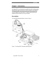
Opsys MW™ Microplate Washer
User’s Guide
IMPORTANT
Please read carefully before using the Opsys MW
Part No. 91000051, Revision B
This manual is published by DYNEX Technologies, Inc.
Questions or comments regarding the content of this manual can be
directed to the address below or to your DYNEX Technologies
representative.
DYNEX Technologies
14340 Sullyfield Circle
Chantilly, VA 20151-1683
Tel.
USA
(703) 631-7800
(800) 288-2354
Fax.
(703) 803-1441
TM
OPSYS MW is a trademark of DYNEX Technologies, Inc.
© 2006 This document is the copyright of DYNEX Technologies and must
not be copied or reproduced in any form without prior consent.
DYNEX Technologies reserves the right to make technical improvements to
this equipment and documentation without prior notice as part of a
continuous program of product development. This manual supersedes all
previous editions.
Warranty and Special Provisions Limited Warranty
DYNEX Technologies products are fully guaranteed for one year against defects in
parts, materials, and workmanship. Defective parts and materials will be replaced
or, at the discretion of DYNEX Technologies, repaired at no charge for a period of
one year and labor required for such replacement or repair will be provided at no
charge for a period of one year, provided that the products are utilized and
maintained in accordance with the instructions in the applicable operating and
servicing manual, and provided further that the products have not, as determined
solely by DYNEX Technologies, been subject to misuse or abuse by the Customer
or other parties unrelated to DYNEX Technologies. DYNEX Technologies makes
no warranty, expressed or implied, as to the fitness of any product for any particular
purposes other than those purposes described in the applicable operating and
servicing manual, nor does DYNEX Technologies make any other warranty,
whether expressed or implied, including merchantability, other than those appearing
on the face hereof. Where DYNEX Technologies guarantees any product, whether
under this Warranty or as a matter of law, and there is a breach of such guarantee,
the Customer’s only and exclusive remedy shall be the replacement or repair of
defective parts and materials, as described above. This shall be the limit of DYNEX
Technologies’ liability. Furthermore, DYNEX Technologies shall not be liable for
incidental or consequential damages. Failure of the Customer to notify DYNEX
Technologies of a claimed defect by registered mail within thirty days of the
discovery thereof shall constitute a waiver of any claim for breach of warranty.
When a product is required by DYNEX Technologies to be installed by a DYNEX
Technologies engineer or technician, the period of this Warranty shall begin on the
date of such installation, provided however, that any use of the product prior to such
installation shall, at sole election of DYNEX Technologies, void this Warranty.
When installation by DYNEX Technologies personnel is not required, the period of
this Warranty shall begin on the date of shipment from DYNEX Technologies. The
period of this Warranty shall begin as described above whether or not the product
has been installed pursuant to a purchase order, and any trial period shall be
deducted from the Warranty period that would otherwise apply under a subsequent
placed purchase order for that product.
Limitation of Liability. Notwithstanding anything to the contrary contained herein,
the liability of Seller (whether by reason of breach of warranty, breach of contract,
tort, or otherwise), including without limitation under any indemnification provision
contained herein, shall be limited to replacement of goods returned to DYNEX
Technologies which are shown to DYNEX Technologies’ reasonable satisfaction to
have been nonconforming or to refund the purchase price, or, if not paid, to a credit
amount of the purchase price therefore.
THE FOREGOING WARRANTIES ARE EXCLUSIVE AND ARE GIVEN AND
ACCEPTED IN LIEU OF ANY AND ALL OTHER WARRANTIES, EXPRESS OR
IMPLIED, INCLUDING WITHOUT LIMITATION, THE IMPLIED WARRANTY OF
MECHANTABILITY AND THE IMPLIED WARRANTY OF FITNESS FOR A
PARTICULAR PURPOSE. NEITHER PARTY SHALL BE LIABLE TO THE OTHER
FOR ANY INCIDENTAL, INDIRECT, SPECIAL, OR CONSEQUENTIAL
DAMAGES.
Table of Contents
Table of Contents
About this Manual
iii
Chapter 1 Introduction
Description
1
1
Programming
Wash Head
Wash Head Positions
Wash Fluid
Waste
2
3
4
5
5
Features
Specifications
Warning Labels
7
9
11
Chapter 2 Installation
Unpacking
13
13
Materials Provided
Hardware Components
Positioning the Instrument
Installing the Wash Head
Installing the Wash Container
Installing the Waste Container
Turning on the System
Chapter 3 Configuration
The Keypad
Menus
The SETUP Menu
The PROGRAM Menu
Configuring the System
Specifying the Wash Head
Specifying Plate Parameters
Displaying the Software Version
Specifying the Pump Parameters
Selecting Clean
Chapter 4 Wash Protocols
Wash Protocol Operations
Creating a New Wash Protocol
Specifying the Header
Specifying Wash Cycle Operations
Ending a MOVE Cycle
Modifying a Wash Protocol
Copying a Wash Protocol
13
15
18
19
20
21
22
23
23
26
27
27
28
29
30
35
36
37
39
39
41
41
45
53
56
61
Chapter 5 Washing a Plate
Preparation
Washing a Plate
63
63
65
Chapter 6 Routine Maintenance
Routine Maintenance Procedures
67
67
Opsys MW™ User’s Guide
i
Table of Contents
Cleaning and Decontamination
Cleaning the Containers
Replacing the Tubing
Pump Calibration
69
70
71
74
Chapter 7 Troubleshooting
Operational Problems
77
77
Chapter 8 Service
Service Procedures
Spare Parts
Returning a Washer for Service
Contact DYNEX Technologies
81
81
82
83
85
Index
86
ii
Opsys MW™ User’s Guide
About this Manual
About this Manual
This manual has been written for laboratory technicians and provides
detailed instructions for using the Opsys MW™ system.
This manual gives you the information needed to:
•
Review safety precautions.
•
Install the Opsys MW™ system.
•
Understand the Opsys MW™ menus.
•
Set the Opsys MW™ system up to suit your exact needs.
•
Create or modify wash protocols.
•
Run wash protocols using the Opsys MW™ system.
•
Perform required preventive maintenance.
•
Troubleshoot the system.
Opsys MW™ User’s Guide
iii
About this Manual
This page is intentionally left blank
iv
Opsys MW™ User’s Guide
Description
Chapter 1 Introduction
The Opsys MW™ is a microprocessor-controlled microplate washing system
that performs wash protocols that are defined by the user. It is designed to
wash all of the wells in one column or one row of a 96-well plate at once.
The washing protocol can be programmed so that all of the columns (or
rows) are washed in the same manner, or different wash cycles can be
applied to specified columns (or rows) on the plate.
Description
The Opsys MW Microplate Washer is shown in Figure 1.
Figure 1. The Opsys MW™ Microplate Washing System
Opsys MW™ User’s Guide
1
Description
Programming
All wash protocols on the Opsys MW™ Microplate Washer are user-defined.
Up to 40 wash protocols can be contained on the system.
Note: Memory limitations may restrict the size
and complexity of an individual wash protocol.
In addition, the system can be configured with up to ten different plate types
so that the wash head positions for each plate type can be specified.
Programming of a new wash protocol (or modifying an existing one) and
configuration of the system are carried out using the keypad and display.
2
Opsys MW™ User’s Guide
Description
Wash Head
The wash head on the Opsys MW™ Microplate Washer contains multiple
sets of dual wash pins. Each set of dual wash pins consists of a
dispense pin and an aspirate pin that are closely spaced so that fluid can
be aspirated from and dispensed into a well simultaneously.
The following wash heads can be fitted on the Opsys MW™:
Wash Head
Description
1x8
Eight sets of dual wash pins for washing a 96-well
microplate one column (8 wells) at a time.
1 x 12
Twelve sets of dual wash pins for washing a
96-well microplate one row (12 wells) at a time.
If a wash head is installed to wash plates by columns, the plates are placed
on the instrument so that the columns of the plate are aligned with the wash
head. If a wash head is installed to wash plates by row, the plate is rotated
90 degrees and placed on the instrument so that the rows of the plate are
aligned with the wash head.
The wash pins are fixed to the wash head. During operation, the wash head
assembly is lowered to insert the wash pins into the wells or raised to
remove the wash pins from the wells. Lowering the wash head assembly
allows the well contents to be aspirated or a bottom wash to be performed.
Raising the wash head assembly allows the plate to be moved so another
column (or row) can be washed or so the wells can be filled.
Opsys MW™ User’s Guide
3
Description
Wash Head Positions
The vertical positions that the wash head can assume are described below.
Each wash head position can be specified by the user to within 0.1 mm.
Note: Procedures for specifying wash head
positions for various plate types are described
on page 30.
4
Wash Head Position
Description
Dispense Height
Positions the aspiration pins slightly
below the top of the well so that fluid can
be dispensed into the well up to a certain
level before it is aspirated.
Well Top
Positions the aspiration pins so they are
aligned with the top of the well.
Aspiration Height
Positions the aspiration pins at the bottom
of the well so that the contents of the well
can be completely aspirated.
Sweep Height
Raises the aspiration pins slightly above
the Aspiration Height (see above) so that
the aspiration pins can be moved back
and forth in the well while the fluid is
being aspirated.
Bottom Wash Height
In protocols with a bottom wash, lowers
the wash head during dispense so that
the force of the dispensed fluid can wash
the bottom of the wells.
Opsys MW™ User’s Guide
Description
Wash Fluid
A single wash fluid is used on the Opsys MW™ Microplate Washer. The
wash fluid is contained in the Wash Container and is dispensed into the
wells whenever a Dispense or Fill operation is specified in the wash
protocol. In addition, wash fluid is dispensed into the purge tray during a
Purge operation.
Dispensing of the fluid from the Wash Container is controlled by a pump
attached to the back of the Opsys MW™ Microplate Washer and a dispense
valve located near the wash head (Figure 1).
Waste
Fluid is removed from the wells during an Aspirate or Dispense operation
and collected in the Waste Container. The Waste Container contains a level
sensor to alert the operator when the container is full.
Removal of the fluid from wells is controlled by lowering the wash head so
that the aspiration pins are immersed into the well fluid (the aspiration
height). A vacuum is applied to the aspiration pins at all times during
operation so that the contents of a well are aspirated whenever the wash
head is lowered to the aspiration height.
Opsys MW™ User’s Guide
5
Description
This page is intentionally left blank
6
Opsys MW™ User’s Guide
Features
Features
The Opsys MW™ system has a number of performance and convenience
features. These are summarised below:
•
Small footprint
•
Up to 40 wash protocols can be programmed
•
Up to ten plate types can be programmed
•
Two wash head configurations (1 x 8 and 1 x 12)
•
On-board self diagnostics
•
SHOW function allows visual verification of wash head height
settings
•
High-level alarm on Waste Container
Opsys MW™ User’s Guide
7
Features
This page is intentionally left blank
8
Opsys MW™ User’s Guide
Specifications
Specifications
Dimensions and Weight
Length
49 cm (19.3 in)
Width
38 cm (15.0 in)
Height
19 cm (7.5 in)
Weight
9.1 kg (20 lbs)
Operation
Dispense Range
50 – 999 µL
Dispense Precision
5% CV (with 300 µL distilled water)
Residual Aspirate Volumes
< 1 µL for U and V bottom plates
< 5 µL for flat bottom plates
Washing Time
Typical 5 cycle wash: 5 min 30 sec
Power
< 100 W
Display
2 by 20 character back lit LCD
Keypad
21 key tactile membrane
Output
Display, Printer, RS232
Environmental
Operating Range
15° C to 30° C
15% to 85% relative humidity (non-condensing)
2000m altitude
Computer Interface
Port
Serial RS-232 port (Service Access)
Baud Rate
19200. Character format
Character Format
7 data bits, 1 stop bit, no parity
Power Requirements
Voltage
Power
Frequency
Main Unit
100 - 240 V
200 VA
50/60 Hz
Line Voltage Variation
± 10%
Line Frequency Variation
± 3 Hz
Opsys MW™ User’s Guide
9
Specifications
Input Ranges
Assay Programming
Assay Name
Up to 10 characters
Password
Up to 8 characters
Move: Start Strip
1 - 8 for 1 x 8 heads and 1 - 12 for 1 x 12 heads (Increment: 1)
Move: End Strip
1 - 8 for 1 x 8 heads and 1 - 12 for 1 x 12 heads (Increment: 1)
Move: #Cycles
1 - 9 (Increment: 1)
Aspirate: Cycles
1 - 9 (Increment: 1)
Dispense
50 - 999 (Increment: 1 µL)
Purge
50 - 9999 (Increment: 1 µL)
Fill
50 - 300 (Increment: 1 µL)
Soak
1 - 999 (Increment: 1 second)
Plate Setup
Plate Name
Up to 10 characters
Dispense Height
001 - 999 (Increment: 1)
Top of Well Height
001 - 999 (Increment: 1)
Aspirate Height
001 - 999 (Increment: 1)
Sweep Height
001 - 999 (Increment: 1)
Sweep Stroke
001 - 999 (Increment: 1)
Bottom Wash: Dispense
Height
001 - 999 (Increment: 1)
Standards
The instrument is designed in accordance with CSA 1010.1-92, UL 3101-1, EN61010-1
and EN61326.
10
Opsys MW™ User’s Guide
Warning Labels
Warning Labels
The Opsys MW™ or its components may contain certain labels that that
either warn the user of a hazard or note an electrical connection. The labels
that may be used on the Opsys MW™ system are described below.
Label
Description
Alternating current is present.
(English) Caution symbol. Refer to the
Routine Maintenance chapter.
(French) Attention (voir documents
d’accompagnement).
(English) Caution, hot surface.
(French) Attention, surface chaude.
Protective conductor terminal.
Earth (ground) terminal.
(English) Caution, risk of electric shock.
(French) Attention, risque de choc électrique.
Opsys MW™ User’s Guide
11
Warning Labels
This page is intentionally left blank
12
Opsys MW™ User’s Guide
Unpacking
Chapter 2 Installation
Unpacking
Materials Provided
The main carton contains the instrument. The contents of this carton are
listed below:
Article
Quantity
Opsys MW™ System
1
Instrument Power Cable
1
Cleaning Wire, Aspirate
1
Cleaning Wire, Dispense
1
Instrument Configuration Report
1
User’s Guide
1
Declaration of Conformity
1
Wash Head, 1 x 8 or 1 x12
1
Plate Holder
1
A sub-carton contains the wash container and waste container assemblies.
The contents of this carton are listed below:
Article
Quantity
Wash Container Assembly
1
Waste Container Assembly
1
Opsys MW™ User’s Guide
13
Unpacking
To unpack the components:
1. Place the Opsys MW™ instrument in the position where it will be
located for use.
2. Place the Wash Container, Waste Container and Foam/Aerosol
Trap at the rear of the instrument.
3. Examine the packaging to be sure that the power cord and other
materials have been removed. Please save packaging material
for future use.
4. Verify that all of the materials listed above have been unpacked.
5. Inspect the components for damage. If damage is observed,
contact your shipper or service representative immediately.
14
Opsys MW™ User’s Guide
Hardware Components
Hardware Components
Hardware components of the Opsys MW™ instrument are shown in
Figure 2 and described below.
Note: The Wash Container, Waste Container
and Foam/Aerosol Trap are external to the
instrument and are not shown in Figure 2.
Wash Head
®
Microtiter Plate
Plate Carrier
Display Panel
Keypad
Figure 2. The Opsys MW™ System
•
Wash Head. The wash head contains sets (1 x 8 or 1 x 12) of dual
wash pins. Each set of wash pins consists of a dispense pin and
an aspirate pin, closely spaced so that fluid can be aspirated from a
well while fluid is being dispensed into the same well. The wash
head moves back and forth to wash each row (or column, depending
on the wash head that is used) of the plate by lowering the wash
pins into the corresponding wells.
•
Plate Carrier. The plate carrier holds the plate in a fixed position so
that the wash pins can be precisely lowered to the correct height and
position in the wells during the washing procedure.
•
Display Panel. The display panel is the means by which the system
communicates to the user. All messages, commands, and wash
parameters entered by the user are displayed.
Opsys MW™ User’s Guide
15
Hardware Components
16
•
Keypad. The keypad is used by the operator to select commands
and enter wash parameters.
•
RS232 Interface. The system includes an RS232 interface so that
an external computer can be connected for technical service
purposes.
•
Wash Container. (Shown in Figure 1). The wash container contains
the wash fluid that is used for Dispense, Fill and Purge operations.
•
Waste Container. (Shown in Figure 1). The waste container
contains the fluid that is aspirated from the wells. A level sensor is
contained inside of the waste container.
Opsys MW™ User’s Guide
Hardware Components
Connectors at the rear of the Opsys MW™ system are shown in Figure 3.
Connections for the power cord, dispense pump power, waste bottle level
sensor, waste bottle vacuum line and an external computer are made at the
rear of the system.
Important: Be sure that the vacuum exhaust
is not obstructed.
Figure 3. Rear View of the Opsys MW™ System
Opsys MW™ User’s Guide
17
Positioning the Instrument
Positioning the Instrument
Determine the area where the system will be located. You will need a firm
and level area that is approximately 51 cm (20 inches) wide, 62 cm (24
inches) deep, and 40 cm (16 inches) high for the Opsys MW™.
18
Opsys MW™ User’s Guide
Installing the Wash Head
Installing the Wash Head
The Wash Head must be located on the Wash Head Arm.
To install the Wash Head:
1. Position the Arm over the Purge Reservoir portion of the Plate
Holder.
2. Place the Wash Head on the two Arm Pins, being careful to
properly seat the Wash Head on the support pins.
3. Level the Wash Head in relation to the Plate Holder and tighten
the two thumbscrews at the front of the Wash Head / Arm
Assembly.
Opsys MW™ User’s Guide
19
Installing the Wash Container
Installing the Wash Container
The dispense tubing and dispense pump power cable must be connected.
To install the Wash Container:
1. Fill the Wash Container with the wash solution that is to be used.
Note: The Wash Container contains up to
4 liters.
2. Insert the Pick-Up Filter into the Wash Container and secure the
cap. Attach the Quick-Connector at the end of the pump tubing,
to the mating connector in the cap.
3. Route the dispense tubing through the upper slot at the front
corner of the instrument and through the routing clips at the front
of the instrument.
4. Connect the end of the dispense tubing to the wash tubing
connector on the wash head.
5. Thread the dispense tubing through the dispense valve.
(Figure 1).
Note: The tubing must be inserted fully into
the dispense valve opening to ensure proper
operation.
6. Connect the dispense pump power cable to the dispense pump
power connector at the rear of the instrument (Figure 3).
20
Opsys MW™ User’s Guide
Installing the Waste Container
Installing the Waste Container
To install the Waste Container and Foam/Aerosol Trap:
1. Insert the Quick-Connect end of the vacuum tubing on the
Foam/Aerosol Trap to the Quick-Connect vacuum connector at
the rear of the instrument Figure 3).
2. Screw on the Waste Container cap.
3. Route the waste tubing through the lower slot at the front corner
of the instrument and through the routing clips at the front of the
instrument.
4. Connect the end of the waste tubing to the waste tubing
connector on the wash head.
5. Connect the waste level sensor cable to the waste level sensor
connector at the rear of the instrument (Figure 3).
Opsys MW™ User’s Guide
21
Turning on the System
Turning on the System
Note: Depending upon local electrical codes,
an uninterruptible power system (UPS) may be
required in your laboratory. A UPS is not
provided with the Opsys MW™ system.
1. Connect the Opsys MW™ to the laboratory electrical supply
outlet.
CAUTION: The Opsys MW™ instrument must
be connected to properly grounded electrical
outlets. Obtain assistance from a qualified
electrician to verify that your electrical outlets
are properly grounded.
Before connecting the power cable, be sure
that the components have been connected to
each other as outlined in the previous section.
2. Push the instrument power switch once. After a series of selftests, the software version is displayed momentarily
Opsys MW. v1.0
before the main menu is displayed:
1: - - - - - - - SETUP PROGRAM
Note: The self-test results indicate whether
the system is operating properly. If a self-test
failure is reported, it is recommended that you
call Technical Service.
Dashes are initially displayed after the wash
protocol number (i.e., 1: - - - - - - - - in the
above example) if a wash protocol has not yet
been named.
22
Opsys MW™ User’s Guide
The Keypad
Chapter 3 Configuration
The Keypad
The keypad is used to access the menus and commands for setting up the
Opsys MW™ entering new wash protocols and running the wash protocols.
The keypad contains scroll keys, function keys, and alphanumeric keys.
The keys on the keypad are shown in Figure 4.
Scroll Keys
Display Panel Function Keys
Scroll Keys
Alphanumeric
Keys
1
ABC
4
JKL
7
STU
2
DEF
5
MNO
8
VWX
3
GHI
6
PQR
9
YZ
ENTER
DEL
START
+-*/=
0
<>_()
CANCEL
Figure 4. Keys on the Keypad
Opsys MW™ User’s Guide
23
The Keypad
The use of each of the keys is summarized below:
Key
Purpose
24
Scroll keys
The functionality of the scroll keys depends upon
what is being displayed.
During display of the main menu (page 26),
pressing the up or down scroll keys will display
successive wash protocol numbers and names (or
dashes, if a protocol is not yet named).
Horizontal scrolls will scroll through selections for
the selected menu. Repeatedly pressing the
horizontal scroll button will show the next two
items in a list. A list with one item will have a
blank entry.
If you are entering or editing information, a
scroll will move the cursor through edit fields.
When editing an existing plate or protocol name,
you may either type over the existing name, or
press the DEL key to delete the characters from
the existing name. (NOTE:To delete the entire
name, either type over it or press the right arrow
key and DEL to delete all characters to the right of
the cursor. The first character of an existing name
cannot be deleted, but it can be overwritten.)
Function keys
Two function keys select the item or execute the
command shown directly above each key on the
second line of the display.
“Del” key
When a modifiable entry is displayed, selecting
Delete will allow the entry to be modified. While
editing a field, selecting Delete removes the
character at the cursor location and all characters
to the right of the cursor.
“Enter” key
Completes an entry of characters, accepts default
prompt data, and displays the next prompt in a
series of commands
“Start” key
Starts a wash protocol. This can only be done
while the main menu is being displayed.
“Cancel” key
Returns to the previous menu within the function
Opsys MW™ User’s Guide
The Keypad
Key
Alphanumeric
Keys
Purpose
The numeral shown on the key is displayed by
pressing the key once. If the key is pressed two to
seven times rapidly, one of the letters on the key
will be displayed. The letter that is displayed
depends upon the number of times the key is
pressed.
Opsys MW™ User’s Guide
25
Menus
Menus
The Opsys MW™ menus are hierarchical and are organised by function.
There are two main menus: Setup and Program.
Menu
Purpose
SETUP
Configure the Instrument
PROGRAM
Create or edit plate washing protocols *
* A protocol includes general information (e.g. the type of microplate to be
washed) as well as a listing of the various steps to be used in the washing
process.
Once the instrument is switched on and the self-test is successfully
completed, the main menu is displayed. It contains SETUP and PROGRAM
menu headers:
1: -------SETUP
PROGRAM
Note: Dashes are initially displayed after the
wash protocol number (i.e., 1: - - - - - - - - in
the above example) if a wash protocol has not
yet been named. Once a wash protocol is
named, the name is displayed after the
protocol number. Refer to page 41 for the
procedure to create and name a wash
protocol.
Display a different wash protocol number and name (there can be up to 40)
by pressing the up or down scroll keys or by entering the protocol number
using the keypad.
Access a menu by pressing the function key beneath the menu header.
Cancel a menu selection and display the previous (higher level) menu by
pressing the CANCEL key.
26
Opsys MW™ User’s Guide
Menus
The SETUP Menu
Press the function key under SETUP to display the SETUP menu
(Figure 5). The SETUP menu contains commands to configure the
instrument.
1: TESTNAME
SETUP
PROGRAM
Select Option
HEAD
PLATE
Select Option
VERSION
CAL.
Figure 5. SETUP Menu
The PROGRAM Menu
Press the function key under PROGRAM to display the PROGRAM menu
(Figure 6). The PROGRAM menu contains commands to name and create a
new wash protocol or to edit an existing wash protocol.
1:TESTNAME
SETUP
PROGRAM
Enter name
–––––––––
(If selected protocol has
not been named)
or:
Edit name
4: WASHNAME
(If selected protocol has
been named and has no
password)
or:
Enter password
(If selected protocol has
been named and has a
password)
Figure 6. PROGRAM Menu
Opsys MW™ User’s Guide
27
Configuring the System
Configuring the System
The Opsys MW™ must be configured before it is operated for the first time.
The commands for doing this are contained in the SETUP menu (Figure 7).
Use ARROW keys to scroll through the menus.
1: TESTNAME
SETUP
PROGRAM
Select Option
HEAD
PLATE
Select Option
VERSION
CAL.
Figure 7. SETUP Menu
The purpose of each command on the SETUP menu is summarised below:
28
Command
Purpose
HEAD
Specify the type of head that is fitted
PLATE
Displays the PLATE menu. The commands on this
menu allow parameters (such as well top height,
dispense height and wash height) for various plate
types to be specified.
VERSION
Displays the version number of the software
CAL.
Displays the CAL. menu. The commands on this
menu allow the pump parameters to be specified.
CLEAN
The CLEAN command enables the washer to be
cleaned automatically at a specified interval. This
feature assists in assuring that tubing and dispense
pins are free from potential salt build up.
Opsys MW™ User’s Guide
Configuring the System
Specifying the Wash Head
The HEAD command allows the installed wash head to be specified:
1. Select SETUP. The display will read:
Select option
HEAD
PLATE
2. Select HEAD. The current wash head selection is displayed in
the upper line:
Wash head?
8
8
If needed, scroll right to view the remaining selection:
Wash head?
12
8
3. Select the desired option using the function key. After the
selection is made, the display will again read:
Select option
HEAD
Opsys MW™ User’s Guide
PLATE
29
Configuring the System
Specifying Plate Parameters
The PLATE command allows plate parameters to be specified for up to 10
plate types.
When setting plate parameters, a default value is displayed for each of the
wash head positions. The default values are factory-set and represent
approximate starting values for each wash head position.
Note: The wash head positions are described
on page 4.
Increasing the value of a wash head position by one unit lowers the head
0.1 mm and decreasing the numerical value of a wash head position by one
unit raises the head 0.1 mm. (e.g. an increment of 20 steps equals one
millimeter of vertical pin travel (+20 = 1mm up, -20 = 1mm down)).
The SHOW command is available when setting each wash head position.
Select SHOW to move the wash head to the indicated position so that the
height can be observed.
For example, when setting dispense height, the default value is 180:
DISP. HEIGHT?
SHOW
180
If, after selecting SHOW, the dispense pins are found to be too low by
approximately 1.0 mm, the dispense height position can be raised by 1.0
mm by entering 170 for the dispense height.
When using the SHOW function when defining the aspirate height, if the
aspirate pins touch the well bottom, increase the aspirate height. If you
cannot move the plate slightly side-to-side and up-down without immediate
interference from the aspirate pins, increase the aspirate height.
30
Opsys MW™ User’s Guide
Configuring the System
To specify parameters for a plate type:
1. Obtain an empty plate of the plate type being specified and place
it in the plate holder.
2. Select SETUP (if needed). The display will read:
Select option
HEAD
PLATE
3. Select PLATE. The name of the first plate is displayed in the
lower line:
Select plate
1: - - - - - - - - - -
Note: Dashes will be displayed if the plate has
not yet been named.
4. If needed, display a different plate number using the up or down
scroll keys (or use the keypad to enter the desired plate number).
When the desired plate number is displayed, press ENTER. The
display will read:
Enter name
---------5. Use the keypad to enter the plate name (up to
10 characters).
Note: Refer to page 23 for instructions on
entering alphabetic characters.
6. Press ENTER. The display will read:
DISP. HEIGHT?
SHOW
180
Note: The default value is displayed. Select
SHOW to move the wash head to the default
dispense position so that the height can be
checked. Then, determine the correct value as
outlined on page 30. Repeat the procedure as
needed.
Opsys MW™ User’s Guide
31
Configuring the System
7. Enter the dispense height using the keypad and press ENTER.
The display will read:
Well top? 160
SHOW
Note: The default value is displayed. Select
SHOW to move the wash head to the default
well top position so that the height can be
checked. Then, determine the correct value as
outlined on page 30. Repeat the procedure as
needed.
8. Enter the desired value using the keypad and press ENTER. The
display will read:
ASP. HEIGHT?
SHOW
380
Note: The default value is displayed. Select
SHOW to move the wash head to the default
aspiration position so that the height can be
checked. Then, determine the correct value as
outlined on page 30. Repeat the procedure as
needed.
9. Enter the desired value using the keypad and press ENTER. The
display will read:
Sweep?
YES
NO
NO
10. Select YES to specify a sweep. The display will read:
All cycles?
YES
NO
NO
Note: If a sweep is specified, the wash pins
are moved up and down and across the
bottom of the well during aspiration to better
remove all droplets of liquid. If NO is selected,
the Wash height? prompt (Step 14) will be
displayed.
Note: Use the sweep function with Flat or “C”
bottom plates only. Sweeping aspirates fluid
more completely from the wells than a regular
aspiration. Sweep all cycles to get the most
thorough well aspiration when using multiple
aspiration cycles, but remember that each
sweep adds seconds to the protocol.
32
Opsys MW™ User’s Guide
Configuring the System
Remember if your protocol requires sweeping,
that must first be specified in the plate
definition used in the protocol.
11. Select YES to specify a sweep on all aspiration cycles. The
display will read:
Sweep height?
SHOW
370
Note: The default value is displayed. Select
SHOW to move the wash head to the default
sweep position so that the height can be
checked. Then, determine the correct value as
outlined on page 30. Repeat the procedure as
needed.
12. Enter the desired value using the keypad and press ENTER. The
display will read:
Sweep stroke?
100
Note: There isn’t a SHOW function for the
sweep stroke. Determine optimum sweep
stroke setting by starting with a small number
and increase it if the residual aspirate volume
is not acceptable. If you run a protocol and
the wash pins strike the sides or bottom of the
well, reduce the sweep stroke and review your
plate setup parameters.
13. Enter the desired value using the keypad and press ENTER. The
display will read:
Bottom wash?
YES
NO
NO
14. Select YES if a bottom wash is to be included. The display will
read:
Wash height?
SHOW
368
Note: The default value for bottom wash
height is displayed. Select SHOW to move the
wash head to the default bottom wash position
so that the height can be checked. Then,
determine the correct value as outlined on
page 30. Repeat the procedure as needed.
Opsys MW™ User’s Guide
33
Configuring the System
15. Enter the desired value using the keypad and press ENTER. The
display will read:
Select option
HEAD
PLATE
Note: If NO is selected for Bottom wash?
(Step 13), the display will read as shown
above.
34
Opsys MW™ User’s Guide
Configuring the System
Displaying the Software Version
The VERSION command displays the software version that is currently
installed on the Opsys MW™ instrument:
1. Select SETUP (if needed). The display will read:
Select option
HEAD
PLATE
2. Scroll right to display the next selection:
Select option
VERSION
CAL.
3. Select VERSION. The display will momentarily read:
Opsys MW.
v1.0
Note: The software version that is displayed
will depend on the version installed in the
instrument.
Opsys MW™ User’s Guide
35
Configuring the System
Specifying the Pump Parameters
The CAL. command allows the calibration values for each pump to be
specified:
1. Select SETUP (if needed). The display will read:
Select option
HEAD
PLATE
2. Scroll right to display the next selection:
Select option
VERSION
CAL.
3. Select the pump pressure (high or low). The display will read:
Pump speed?
190
4. Enter the desired value using the keypad and press ENTER. The
display will read:
Slope?
2.1
Note: The Slope and Intercept values should
only be changed by DYNEX Technologies
Service Personnel.
5. Press ENTER to keep the existing value. The display will read:
Intercept?
24
6. Press ENTER to keep the existing value. The display will again
read:
Select option
VERSION
CAL.
Note: Refer to page 74 for additional pump
calibration instructions.
36
Opsys MW™ User’s Guide
Configuring the System
Selecting Clean
The CLEAN command enables the washer to be cleaned automatically at a
specified interval.
1. Scroll right to display the next section:
Select option
CLEAN
2. Select CLEAN. The display will read:
Auto Clean?
YES
NO
3. Select YES if you want periodic automatic cleaning. The display will
read:
Interval (Hrs)
1
4. Enter the desired interval using the up/down scroll keys and press
ENTER.
Note: The minimum interval is 1 hour, and the
maximum interval is 9 hours.
The display will read:
Fluid Volume?
2500
5. Enter the desired volume of fluid to be dispensed.
Note: A cleaning volume ranging from 50 to
9,999 microliters can be entered. Follow the
instructions on page Error! Bookmark not
defined. for refilling the wash container.
6. Press ENTER. The display will read:
Select option
CLEAN
Opsys MW™ User’s Guide
37
Configuring the System
This page is intentionally left blank
38
Opsys MW™ User’s Guide
Wash Protocol Operations
Chapter 4 Wash Protocols
Wash Protocol Operations
A wash protocol consists of a series of Purge, Move, Soak, Aspirate,
Dispense and Fill operations.
Purge, Move and Soak can be carried out in any sequence. Aspirate,
Dispense and Fill can only be carried out within a Move operation, and
there cannot be a Move within a Move.
Each of these operations is described below:
Operation
Description
Purge
Dispenses fluid from the dispense wash pins while
the wash head is positioned over the purge tray
Note: Purge is usually
carried out at the beginning
of a wash protocol to rinse
the dispense wash pins and
remove air bubbles.
Move
Performs Aspirate, Dispense, Fill and/or Soak
operations on specified strips of the Microplate
Aspirate
Removes the contents of a well by positioning the
wash pins at the aspiration height in the well and
aspirating the liquid from the wells
A sweep may also be performed during Aspirate.
Note: The aspirate height
and sweep parameters for a
particular plate type are
specified during system
configuration (30).
If a sweep is specified during
configuration, the wash pins
are moved back and forth
during the aspiration cycle.
Opsys MW™ User’s Guide
39
Wash Protocol Operations
Operation
Description
Dispense
Dispenses a specified amount of fluid into the wells
after aspirating the contents of the wells (i.e.
wherever a DISPENSE step is added to a protocol,
the OPSYS MW will automatically aspirate the
wells before dispensing more fluid in order to
prevent a well overflow). If a bottom wash is
specified, the wash head is then lowered to the
bottom wash position so that fluid will be aspirated
from the bottom of the wells while fluid is being
dispensed.
Note: The dispense height
for a particular plate type is
specified during system
configuration (page 30).
40
Soak
The contents of the wells are allowed to equilibrate
for the specified number of seconds.
Fill
The wells are filled with a specified amount of fluid.
Opsys MW™ User’s Guide
Creating a New Wash Protocol
Creating a New Wash Protocol
Specifying the Header
NOTE: Pressing CANCEL while creating or
editing a protocol will bring you back to the
main menu without saving your changes.
or
(or use keypad)
Select one of the 40 protocol numbers.
↓
PROGRAM
Select PROGRAM from the main menu.
↓
(keypad)
Enter a protocol name (up to 9 characters).
↓
(keypad)
Enter an optional password.
NOTE: If the password for a protocol is lost, the ability
to access the method and the method position are also
lost.
↓
or
(or use keypad)
Select the plate type.
↓
Variable strips?
Specify whether the operator will be prompted at run
time to enter the number of strips to be washed (avoids
reprogramming the number of strips).
↓
Constant timing?
(If Variable strips? is YES). Specify whether the time
for washing any number of strips on a plate is constant.
Figure 8. Specifying the Wash Protocol Header
After the wash protocol header information is defined, the specific steps in
the wash protocol are specified.
The procedures for defining the wash protocol header are described in the
following pages. The procedures for specifying the steps in a wash protocol
are described beginning on page 45.
Opsys MW™ User’s Guide
41
Creating a New Wash Protocol
To create a new wash protocol header:
1. Display the main menu.
1: - - - - - - - - - SETUP
PROGRAM
2. Use the up or down scroll keys to display the protocol number (or
use the keypad to enter the protocol number) that is to be
created:
6: - - - - - - - - - SETUP
PROGRAM
Note: Dashes will be displayed if a protocol
has not yet been named.
3. Select PROGRAM. The name of the wash protocol is displayed
in the lower line:
Enter name
---------4. Use the keypad to enter the protocol name (up to 9 characters)
and press ENTER. The display will read:
Password?
YES
NO
Note: Refer to page 24 for instructions on
entering alphanumeric characters.
5. Select YES if the protocol is to be password protected. The
display will read:
Enter password
********
Note: If NO is selected, the Select plate
prompt (Step 7) will be displayed.
6. Enter the password, (up to eight numeric characters) and press
ENTER. The display will read:
Confirm password
********
42
Opsys MW™ User’s Guide
Creating a New Wash Protocol
7. Re-enter the password and press ENTER. The display will read:
Select plate
2: DYNEX_1
Note: The plate name that is shown is an
example. The actual name will be the plate
name that is entered for that plate type during
system configuration (see page 30).
8. Use the up and down scroll keys to select the plate type (or enter
the number using the keypad) to be used and press ENTER. The
display will read:
Variable strips?
YES
NO
Note: “Variable Strips” is used to run an
established protocol on fewer strips than
originally specified in the “MOVE” cycle(s) of
an established protocol.
If YES is selected, the operator will be
prompted at run time to specify the number of
strips that are to be washed. Processing will
begin on the first strip selected in the “MOVE”
cycle and will end on the total number of strips
entered at run time (e.g. the protocol states:
“Move 3-12 1 cycle(s)” and at run time, 2
strips are entered, only strips 3 and 4 will be
processed).
9. If YES is selected, the display will read:
Constant timing?
YES
NO
Note: If NO is selected for Variable strips?,
the Select option prompt will be displayed
(see below).
Note: The Constant Timing prompt only
appears if you are using Variable Strips.
Opsys MW™ User’s Guide
43
Creating a New Wash Protocol
10. Select YES if the total elapsed time for washing any number of
strips within a plate is to be constant. The display will read:
Select option
MOVE
PURGE
The sequential steps in the wash protocol can now be specified,
as outlined on page 45.
44
Opsys MW™ User’s Guide
Creating a New Wash Protocol
Specifying Wash Cycle Operations
The final step in creating a wash protocol is to specify individual operations
within the wash protocol.
An example of a wash protocol is shown in 45. In this example, the dispense
wash pins are purged, and then a Dispense and Aspirate are carried out
twice on each of the 12 strips (columns) of a 96-well Microtiter® plate.
Finally, after all 12 strips have been washed twice, the contents of the
Microtiter plate are allowed to soak (equilibrate) for another 600 seconds.
PURGE
Purge the dispense pins.
↓
MOVE
(2 Cycles)
Specify the starting strip and ending strip for each cycle
and the number of cycles to be performed.
↓
DISPENSE
(3 Times)
For each strip, perform dispense three times.
↓
ASPIRATE
For each strip, perform one aspiration cycle.
↓
END LOOP
End the cycle.
↓
After the two Move cycles have been completed, allow
the contents to equilibrate for 600 seconds.
SOAK
↓
END
End the wash protocol.
Figure 9. Example of a Wash Protocol
The procedures for specifying the steps in this and other wash protocols are
described on the following pages.
Opsys MW™ User’s Guide
45
Creating a New Wash Protocol
To specify a Purge:
Note: A purge must be performed outside of a
Move cycle.
1. Display the header information for the selected wash protocol, as
outlined on page 41. The display will read:
Select option
MOVE
PURGE
2. Select PURGE. The display will read:
Fluid volume?
350
3. Use the keypad to enter the volume of fluid to be dispensed.
Note: A purge volume ranging from 50 to
9,999 microliters can be entered.
4. Press ENTER. The display will read:
Select option
MOVE
46
PURGE
Opsys MW™ User’s Guide
Creating a New Wash Protocol
To specify a Move cycle:
1. Display the header information for the selected wash protocol, as
outlined on page 41. The display will read:
Select option
MOVE
PURGE
2. Select MOVE. The display will read:
Start strip?
1
3. Using the keypad, enter the strip number where the move cycle
should start.
4. Press ENTER. The display will read:
End strip?
12
5. Using the keypad, enter the strip number where the move cycle
should end.
6.
Press ENTER. The display will read:
Cycles?
1
7. Using the keypad, enter the number of the specified move cycles
that are to be sequentially performed.
Note: Between 1 and 9 Move cycles can be
specified.
8. Press ENTER. The display will read:
Select option
ASPIRATE DISPENSE
9. Specify Aspirate, Dispense, Soak and Fill operations in the
sequence as they are to be carried out, as described in the
following sections.
10. When all of the operations for the Move cycle have been
sequentially specified, specify End Loop to designate the end of
the Move cycle.
Opsys MW™ User’s Guide
47
Creating a New Wash Protocol
To specify an Aspiration (within a Move):
Note: An Aspirate or Dispense must be
performed within a Move cycle.
1. Select ASPIRATE. The display will read:
Cycles?
1
2. Using the keypad, enter the number of aspiration cycles that are
to be to be performed within the MOVE cycle.
3. Press ENTER. The display will read:
Select option
ASPIRATE DISPENSE
48
Opsys MW™ User’s Guide
Creating a New Wash Protocol
To specify a Dispense (within a Move):
Note: A Dispense or Aspirate must be
performed within a Move cycle.
1. Select DISPENSE. The display will read:
Fluid volume?
350
2. Use the keypad to enter the volume of fluid to be dispensed.
Note: A volume ranging from 50 to 999
microliters can be entered.
3. Press ENTER. If a bottom wash is specified for the plate being
used, the display will read:
Bottom Wash?
YES
NO
NO
Note: If the protocol requires bottom washing,
that must first be specified in the plate
definition used in the protocol.
If a bottom wash is not specified for the plate being used or if NO
is selected for the Bottom Wash? prompt, the display will read:
Select option
ASPIRATE DISPENSE
4. Select YES if a bottom wash is to be included. The display will
read:
Fluid volume?
350
5. Use the keypad to enter the volume of fluid to be dispensed
during the bottom wash.
Note: A volume ranging from 50 to 999
microliters can be entered.
Opsys MW™ User’s Guide
49
Creating a New Wash Protocol
6. Press ENTER. The display will read:
Cycles?
1
7. Use the keypad to enter the number of bottom wash cycles to be
performed and press ENTER. The display will read:
Select option
ASPIRATE DISPENSE
50
Opsys MW™ User’s Guide
Creating a New Wash Protocol
To specify a Soak (within a Move):
Note: A Soak can be performed either within
or outside of a Move cycle. The procedure
below describes the procedure for specifying a
soak within a Move cycle.
The procedure for specifying a Soak outside
of a Move cycle is described on page 50.
1. Scroll right to display the next selection. The display will read:
Select option
SOAK
FILL
2. Select SOAK. The display will read:
Duration?
5
3. Enter the desired soak duration using the keypad.
Note: A soak duration ranging from 1 to 999
seconds can be entered.
4. Press ENTER The display will read:
Select option
SOAK
Opsys MW™ User’s Guide
FILL
51
Creating a New Wash Protocol
To specify a Fill (within a Move):
Note: A Fill must be performed within a Move
cycle.
1. Scroll right to display the next selection. The display will read:
Select option
SOAK
FILL
2. Select FILL. The display will read:
Fluid volume?
50
3. Use the keypad to enter the volume of fluid to be dispensed
during well filling.
Note: A volume ranging from 50 to 300
microliters can be entered.
4. Press ENTER. The display will read:
Select option
SOAK
52
FILL
Opsys MW™ User’s Guide
Creating a New Wash Protocol
Ending a MOVE Cycle
1. Scroll right to display the next selection. The display will read:
Select option
SOAK
FILL
2. Scroll right to display the next selection. The display will read:
Select option
END LOOP
3. Select END LOOP. The display will read:
Select option
MOVE
PURGE
Opsys MW™ User’s Guide
53
Creating a New Wash Protocol
To specify a Soak (outside of a Move):
Note: A Soak can be performed either within
or outside of a Move cycle. The procedure
below describes the procedure for specifying a
soak outside of a Move cycle.
The procedure for specifying a Soak within a
Move cycle is described on page 47.
1. Scroll right to display the next selection. The display will read:
Select option
SOAK
END
2. Select SOAK. The display will read:
Duration?
5
3. Enter the desired soak duration (1 to 999 seconds) using the
keypad.
Note: A soak duration ranging from 1 to 999
seconds can be entered.
4. Press ENTER The display will read:
Select option
SOAK
54
END
Opsys MW™ User’s Guide
Creating a New Wash Protocol
To specify the End of the wash protocol:
1. Scroll right to display the next selection. The display will read:
Select option
SOAK
END
2. Select END. The display will read:
1: NAME_01
SETUP
Opsys MW™ User’s Guide
PROGRAM
55
Modifying a Wash Protocol
Modifying a Wash Protocol
An existing wash protocol can be modified by using many of the same
commands that are used to create a wash protocol.
To modify a wash protocol:
1. Display the main menu:
1: NAME_01
SETUP
PROGRAM
2. Use the up and down scroll keys to select the wash protocol to
be modified (or enter the number using the keypad). The display
will read:
4: NAME_04
SETUP
PROGRAM
3. Select PROGRAM. If the wash protocol is password protected,
the display will read:
Enter password
Note: If a Password is not specified for the
selected wash protocol, the display will read
as shown in Step 5.
4. Enter the Password using the keypad and press ENTER.
Note: If the Password is entered incorrectly an
error message is displayed. The operator is
allowed three attempts to enter the password.
After the third attempt, the main menu
(Step 1) will again be displayed.
Note: If the password for a protocol is lost, the
ability to access the method and the method
position are also lost.
5. After a password is successfully entered (or if a password was
not specified for the selected protocol), the display will read:
Edit name
4: NAME_04
56
COPY
Opsys MW™ User’s Guide
Modifying a Wash Protocol
6. The cursor is positioned under the first character of the name. If
the name is to be changed, enter the name using the keypad and
press ENTER. The first step of the wash protocol will be
displayed:
MOVE 1-12
DELETE
1 Cycles
EDIT
Note: The example above shows the MOVE
operation as the first step in the protocol. The
actual operation that is shown will depend
upon the protocol that is being modified.
Note: For each step that is displayed, the
operation being carried out and the value for
that operation are displayed. In the MOVE
example above, the Start Strip is 1, the End
Strip is 12, and the number of cycles is 1.
Opsys MW™ User’s Guide
57
Modifying a Wash Protocol
To modify a wash operation:
1. Select EDIT while the operation is displayed. The first step in the
operation is displayed:
Start strip?
1 Cycles
Note: The actual step that is displayed
depends upon the operation being modified.
2. Modify the operation, using the same procedures as when
creating a new wash protocol.
MOVE 1-10
DELETE
1 Cycles
EDIT
Note: In the example above, the End Strip was
changed from 12 to 10. The actual values that
are displayed will depend upon the operation
being modified and the new value(s) entered.
Note: Once the move loop is modified, the
display will no longer read as shown above.
Instead, it will display the first command in the
move loop or End of Move.
3. Press ENTER to display the next step on the wash protocol.
58
Opsys MW™ User’s Guide
Modifying a Wash Protocol
To delete a wash operation:
1. Select DELETE while the operation is displayed. The operation is
removed from the wash protocol.
Note: If a MOVE operation is deleted, all
operations within the MOVE (i.e., Aspirate,
Dispense, Soak and Fill) are also removed.
Opsys MW™ User’s Guide
59
Modifying a Wash Protocol
To insert a wash operation:
1. Scroll right while the operation that the new operation is to
precede is displayed:
MOVE 1-10
INSERT
1 Cycles
Note: The inserted operation will take place
immediately before the operation that is
displayed.
2. Select INSERT. The display will read:
Select option
MOVE
PURGE
3. Select the option that is to be inserted, using the same procedure
as when creating a new wash protocol.
60
Opsys MW™ User’s Guide
Copying a Wash Protocol
Copying a Wash Protocol
An existing wash protocol can be copied to another program number. If a
wash protocol is already in that location, it will be overwritten.
To copy a wash protocol:
1. Display the main menu:
1: NAME_01
SETUP
PROGRAM
2. Use the up and down scroll keys to select the wash protocol to
be modified (or enter the protocol number using the keypad). The
display will read:
4: NAME_04
SETUP
PROGRAM
3. Select PROGRAM. If the wash protocol is password protected,
the display will read:
Enter password
4. Enter the Password using the keypad and press ENTER.
Note: If the Password is entered incorrectly an
error message is displayed. The operator is
allowed three attempts to enter the password.
After the third attempt, the main menu will be
displayed.
5. After a password is successfully entered, the display will read:
Edit name
4: NAME_04
COPY
6. Select COPY. The display will read:
Copy to?
7
Note: The protocol number that is displayed
represents the first free protocol number, if any
are available.
Opsys MW™ User’s Guide
61
Copying a Wash Protocol
7. Using the keypad, enter the number of the wash protocol that the
commands are to be copied to. If a wash protocol already exists
at that location the display will read:
Overwrite test?
YES
NO
NO
8. Select YES. The display will read:
7: NAME_04
SETUP
62
PROGRAM
Opsys MW™ User’s Guide
Preparation
Chapter 5 Washing a Plate
Once the parameters for at least one plate type and one wash protocol have
been set, the system can be used to wash a plate.
Preparation
The only preparation that is required is to check the fluid levels in the Wash
Container and the Waste Container. Service the containers if necessary.
To empty the waste container:
1. Unscrew the cap of the Waste Container. Lay the cap and level
sensor assembly on a paper towel.
2. Discard the waste in accordance with local regulations.
3. Rinse the waste container with deionized water. Discard the rinse
water.
Note: If desired, the waste container can be
disinfected with a 10% (v/v) solution of
household bleach in water.
4. Place the level sensor and tube back into the Waste Container
and screw the cap on.
Opsys MW™ User’s Guide
63
Preparation
To refill the wash container:
1. Separate the dispense line quick-connector in the cap of the
Wash Container.
2. Unscrew the cap of the Wash Container and lay it and the PickUp Filter on a clean paper towel.
3. Fill the Wash Container with the wash fluid that is being used.
Note: If the wash solution is being changed,
discard the contents of the Wash Container
and thoroughly clean it before filling it with the
new wash solution.
4. Place the Pick-Up Filter into the Wash Container and screw the
cap on. Re-connect the dispense line quick-connector.
64
Opsys MW™ User’s Guide
Washing a Plate
Washing a Plate
A plate is washed by positioning it on the carrier block, selecting the wash
protocol to be run, and pressing the START key.
To wash a plate:
1. (If needed) Turn on the instrument. The display will read:
1: TESTNAME
SETUP
PROGRAM
2. Place the microplate on the plate carrier.
Note: Be sure that the plate position on the
carrier plate corresponds to the wash head
configuration that is being used. For example,
if a 1 x 8 head is used, be sure that the plate is
positioned with the columns aligned with the
wash head rather than perpendicular to the
wash head.
3. Select the desired wash program using the up or down scroll
keys or by entering the wash protocol number using the keypad.
Note: Before starting the wash protocol, verify
that the correct wash protocol name is
displayed.
4. Press the START key. The wash program will be automatically
carried out.
Note: If variable strips was specified for the
wash protocol, you will be prompted to enter
the strips that are to be washed before the
wash will commence.
Opsys MW™ User’s Guide
65
Washing a Plate
This page is intentionally left blank
66
Opsys MW™ User’s Guide
Routine Maintenance Procedures
Chapter 6 Routine Maintenance
Routine Maintenance Procedures
The Opsys MW™ Microplate Washer is constructed from materials that
resist chemical attack. If a spill occurs, it should be cleaned up as soon as
possible using a cloth moistened with a mild laboratory detergent (If needed,
dilute the laboratory detergent according to the manufacturer’s directions).
The following periodic maintenance procedures are required for the
Opsys MW:
Daily maintenance:
•
Verify that the self-test passes, by observing Arm movement and the
absence of error messages.
•
Clean the plate carrier, using a moist towel.
•
Clean the external surfaces, using a moist towel.
Weekly maintenance:
•
Empty the Wash Container and clean it.
The wash solution should be replaced at least once a week. The
Wash Bottle should be cleaned whenever fresh wash solution is
required.
Note: If particulate matter is observed in the
Wash Bottle, the wash solution should be
discarded at once.
To replace the wash solution:
1. Discard any wash solution that is left in the Wash Bottle.
2. Rinse the Wash Bottle with fresh solution.
3. Fill the Wash Bottle with wash solution.
4. Purge the system to ensure that all of the old solution is removed
from the tubing.
•
Empty the Waste Container and clean it.
•
Inspect the tubing between the Wash Bottle and the Wash Head.
•
Inspect the tubing between the Wash Head and the Waste
Bottle.
•
The tubing should be replaced if it has cracks, is cloudy,
remains pinched, or is otherwise defective.
Six month maintenance:
Opsys MW™ User’s Guide
67
Routine Maintenance Procedures
•
Replace the dispense (Wash) tubing.
•
Replace the aspirate (Waste) tubing.
Note: The dispense tubing and aspiration
tubing may need to be replaced more
frequently than every six months, depending
upon the frequency of use and the severity of
operating conditions.
Contact DYNEX Technologies for information on
replacement tubing.
•
Replace the in-line hydrophobic filter.
If the system will not be used for a period of time, the system should
be flushed with de-ionized water so that buffers and/or reagents
used to wash the plates are not deposited on the Wash Head or
other components of the system.
As required maintenance:
•
68
Pump Calibration (page 74)
Opsys MW™ User’s Guide
Cleaning and Decontamination
Cleaning and Decontamination
The Opsys MW™ is constructed from materials that resist chemical attack.
Spills should be cleaned as soon as possible. If you need to decontaminate
the Opsys MW™ instrument (for example, before servicing the instrument),
clean the system and then decontaminate it as described below.
CAUTION: Always disconnect the power cable
before cleaning the instrument.
To clean the system:
1. Clean external surfaces with a cloth moistened with mild
laboratory detergent.
Note: If needed, dilute the laboratory
detergent according to the manufacturer’s
instructions before using.
To decontaminate the system:
1. Wipe the surfaces with a cloth moistened with 10% bleach or
70% alcohol.
Opsys MW™ User’s Guide
69
Cleaning the Containers
Cleaning the Containers
Procedures for emptying, cleaning and refilling the Wash Container and the
Waste Container are described below.
To empty and clean the waste container:
1. Unscrew the cap of the Waste Container. Lay the cap and level
sensor assembly on a paper towel.
2. Discard the waste in accordance with local regulations.
3. Rinse the waste container with deionized water. Discard the rinse
water.
Note: If desired, the waste container can be
disinfected with a 10% (v/v) solution of
household bleach in water.
4. Place the level sensor and tube back into the Waste Container
and screw the cap on.
To refill the wash container:
1. Separate the dispense line quick-connector in the cap of the
Wash Container. Unscrew the cap and lay it and the Pick-Up
Filter on a clean paper towel.
2. Fill the Wash Container with the wash fluid that is being used.
Note: If the wash solution is being changed,
discard the contents of the Wash Container
and thoroughly clean it before filling it with the
new wash solution.
3. Place the Pick-Up Filter into the Wash Container and screw the
cap on. Reconnect the dispense line quick-connector.
70
Opsys MW™ User’s Guide
Replacing the Tubing
Replacing the Tubing
To replace the dispense tubing:
1. Separate the dispense line quick-connector in the cap of the
Wash Container. Unscrew the cap, lay it and the Pick-Up Filter
on a clean paper towel.
2. Discard the contents of the Wash Container. Thoroughly rinse
the container with deionized water and let it dry.
3. Disconnect and discard the Wash Container Internal Tube and
pick-up filter that is attached to the barb on the Quick Connect
Fitting in the Cap.
4. Replace the Wash Container Internal Tube and pick-up filter.
5. Remove the Quick Connect Fitting from the Pump Tube that is
attached to the Pump Inlet. Disconnect the tube from the pump
and discard.
6. Reattach the Quick Connect Fitting to a new length of Pump
Tube and attach the free end of the tube to the Pump Inlet.
7. Disconnect both ends of the Dispense Tube that is attached to
the Pump Outlet and the Wash Head, remove the tubing from the
dispense valve and discard.
8. Attach the short length of larger diameter tube to the Pump
Outlet and to the other end fit the larger barb of the Reducer
Fitting. To the small end of the Reducer fit the long length of
small diameter dispense tube and attach the free end to the
Wash Head
9. Route the dispense tubing through the upper slot in the front
corner of the instrument and through the routing clips at the front
of the instrument. Fit the dispense tubing in the dispense valve.
10. Fill the Wash Container with fresh wash fluid. Place the Wash
Container Internal Tube and pick-up filter back into the Wash
Container and screw the Cap on. Reconnect the dispense line
quick-connector.
Opsys MW™ User’s Guide
71
Replacing the Tubing
To replace the vacuum tubing:
Note: This procedure describes replacement
of the vacuum tubing connecting the Waste
Container to the Foam/Aerosol Trap. The
vacuum tubing connecting the Foam/Aerosol
Trap to the rear of the instrument should not
require changing.
1. Unscrew the Cap of the Waste Container, lay it and the level
sensor assembly on a clean paper towel.
2. Discard the contents of the Waste Container in accordance with
local regulations. Thoroughly rinse the container with deionized
water and let it dry.
3. Disconnect the vacuum tubing from the connector in the Cap and
from the connector in the Foam/Aerosol Trap. Discard the old
tube.
4. Obtain a new length of vacuum tubing.
5. Connect one end of the vacuum tubing to the connector in the
Waste Container Cap and the other end to the connector in the
Foam/Aerosol Trap.
6. Place the level sensor assembly back into the Waste Container
and screw the Cap on.
72
Opsys MW™ User’s Guide
Replacing the Tubing
To replace the waste tubing:
1. Unscrew the Cap of the Waste Container and lay it with the level
sensor assembly on a clean paper towel.
2. Discard the contents of the Waste Container in accordance with
local regulations. Thoroughly rinse the container with deionized
water and let it dry.
3. Disconnect the waste tubing from the connector on the Waste
Container cap and from the waste tubing connector on the wash
head.
4. Remove the waste tubing from the instrument.
5. Obtain a new length of waste tubing.
6. Route the waste tubing through the lower slot at the front corner
of the instrument and through the routing clips at the front of the
instrument.
7. Connect one end of the waste tubing to the waste tubing
connector on the wash head and connect the other end to the
connector in the Waste Container cap.
8. Place the level sensor assembly back into the Waste Container
and screw the Cap on.
Opsys MW™ User’s Guide
73
Pump Calibration
Pump Calibration
Each Opsys MW™ washer manifold, or head, (e.g., 1 x 8, 1 x 12) has three
calibration values stored in memory. These values are calculated and stored
during manufacture at DYNEX Technologies. When the Opsys MW
configuration is changed from one manifold to another, the corresponding
calibration settings will be recalled by correctly setting the head size using
the SETUP/HEAD feature (refer to page 28 for Specifying the Wash Head).
This calibration protocol may be used at any time to verify the performance
of the Opsys MW washer.
IMPORTANT! It is recommended that this protocol be completed if any
fluid-carrying component of the Opsys MW is replaced. This protocol may
also be used to recalibrate the Opsys MW if a new wash buffer with different
viscosity is used. Customize the protocol to emulate your assay, using the
appropriate dispense volume, pump speed and fluid density.
Calibration Protocol:
1. Define a flat bottom plate profile using the SETUP/PLATE
function (refer to page 30 for Specifying Plate Parameters).
2. Program an assay to dispense 200µl/well into columns 1-12
(refer to page 41 for Creating a New Wash Protocol).
3. Obtain a clean, dry flat bottom 96-well styrene plate.
4. Weigh the plate and record the empty plate weight in grams.
5. Run the assay programmed in Step 2. (This assay will dispense
200µl to all 96 wells in the plate.)
6. Weigh the plate and record the filled plate weight in grams.
7. Calculate the actual dispensed volume and % error using the
following formulas:
74
A.
Actual Volume = [(Full weight – Empty weight) x 1000mg/g] /
(96 wells x fluid density)
B.
%Error = 100 x (Actual Volume – Target Volume)/Target
Volume
Example:
Empty plate weight: 48.38g
Full plate weight: 67.42g
Density of water at 20°C = 0.998mg/µl
Actual Volume = [(67.42 – 48.38) x 1000]/(96 x 0.998) =
198.7µl/well
%Error = 100 x (198.7 – 200)/200 = -0.6%
Opsys MW™ User’s Guide
Pump Calibration
8. If the dispensed volume is too high, decrease the pump speed
using the SETUP/CAL function (refer to page 36).
• A pump speed change of -10 units roughly corresponds to a
well volume change of -10µl.
9. If the dispensed volume is too low, increase the pump speed
using the SETUP/CAL function (refer to page 36).
• A pump speed change of +10 units roughly corresponds to a
well volume change of +10µl.
10. Repeat Steps 3-9 until fluid is dispensed with the accuracy
required. (e.g., Error less than or equal to ±5%)
Opsys MW™ User’s Guide
75
Pump Calibration
This page is intentionally left blank
76
Opsys MW™ User’s Guide
Operational Problems
Chapter 7 Troubleshooting
Operational Problems
Problems that may occur during normal operation of the Opsys MW™ are
described below. For each problem, the symptom, probable cause and the
means for resolving the problem are shown.
Symptom
Probable Cause
Resolution
The instrument
fails to power up.
The cord is not
connected.
Check that the cord is
plugged into the
instrument and into the
electrical outlet.
Verify that the electrical
outlet is not controlled by
a switch or timer.
Verify that there is power
at the electrical outlet by
plugging in and checking
another device.
Liquid is not
dispensed from the
dispense pins.
The powerstrip is
faulty.
Replace the powerstrip.
The fuse is
blown.
Service is required.
The breaker is
tripped.
Service is required.
The power supply
is defective.
Reset the breaker.
The dispense
pins are clogged.
Remove the wash head
assembly and clean it
using the manifold head
cleaning wire. Then run a
purge. Service is required
if problem persists.
The Wash
Container is
empty.
Refill the Wash Container.
Opsys MW™ User’s Guide
77
Operational Problems
Symptom
Probable Cause
Resolution
Liquid is not
dispensed from the
dispense pins
(continued).
The wash
protocol is
incorrectly
defined.
Check the system
configuration and wash
protocol for the number
fluids and fluid volume.
The dispense
tubing or the
dispense pump
power supply is
not connected.
Verify that the dispense
tubing and the dispense
power supply are
connected (see page 20).
The dispense
tubing is sealed
shut at the
dispense valve.
Remove the tubing from
the dispense valve and
massage the tubing to
release it. Replace the
tubing into the dispense
valve at a different
location.
Purge the tubing more
frequently.
Replace the tubing.
The dispense
valve does not
open.
Service is required.
The wash head
manifold tubing is
blocked.
Remove the wash head
assembly and clean it
using the manifold head
cleaning wire. Then run a
purge. Service is required
if problem persists.
There is a
pressure leak.
Check the seals and
tubing for leaks.
Check for air leaks.
Reseat the tubing in the
dispense valve.
Liquid is dispensed
continuously from
the dispense pins
78
The dispense
pump is faulty.
Service is required.
The dispense
tubing is not
inserted in the
dispense valve.
Insert the dispense tubing
into the dispense valve
(see page 20).
Opsys MW™ User’s Guide
Operational Problems
Symptom
Probable Cause
Resolution
Dispense volumes
are incorrect.
The dispense
pins are leaking.
Check the pins, seals and
tubing for leaks.
The dispense
pressure is low.
Check the seals and
tubing for leaks.
Check for air leaks.
Reseat the tubing in the
dispense valve.
Aspiration is not
complete.
The dispense
pins are clogged.
Remove the wash head
assembly and clean it
using the manifold head
cleaning wire. Then run a
purge. Service is required
if problem persists.
Incorrect
Calibration
The aspiration
pins are clogged.
Recalibrate Pump
The aspiration pin
height is set too
high.
Repeat the plate setup
procedure (page 30).
Remove the wash head
assembly and clean it
using the manifold head
cleaning wire. Service is
required if problem
persists.
The seal on the
Check the seal and waste
waste container is tubing for leaks.
leaking.
The wash
protocol is not
optimized.
If the bottoms of the plate
wells are flat, use a
sweep.
Add additional aspiration
cycles to the wash
protocol.
Aspiration tubing
may be blocked
or kinked.
Check the aspiration
tubing and remove any
blockages or kinks.
The vacuum
exhaust may be
blocked.
Remove any obstructions
at the vacuum exhaust
(see page 17).
The vacuum
pump may be
contaminated by
overflow.
Service is required.
Opsys MW™ User’s Guide
79
Operational Problems
Symptom
Probable Cause
Resolution
Aspiration is not
complete.
(continued)
Hydrophobic filter
may be
obstructed.
Replace filter.
High Waste Level
is displayed.
The Waste
Container is full.
Empty the Waste
Container (see page 70).
The waste level
sensor cable is
not plugged in.
Connect the waste level
sensor cable (see
page 17).
The waste level
sensor connector
is defective.
Service is required.
The waste level
sensor detector is
reversed.
Service is required.
The waste tubing
is blocked.
Remove the waste tubing
from the rear of the
instrument (see page 17).
Check the waste tubing
(and aspiration tubing)
and remove any
blockages or kinks.
The waste
container is
damaged or
defective.
Replace the waste
container.
Motion of the
wash head is
being blocked.
Check the wash head
vicinity and remove any
obstacles.
The motor is
defective.
Service is required.
Motion of the
wash head is
being blocked.
Check the wash head
vicinity and remove any
obstacles.
The motor is
defective.
Service is required.
The wash
protocol exceeds
the memory limit.
Reduce the number of
steps in the wash protocol
and try again.
The waste
container is
deformed.
X Motor Home
Error is displayed.
Z Motor Home
Error is displayed.
Test Too Large is
displayed.
80
Opsys MW™ User’s Guide
Service Procedures
Chapter 8 Service
Service Procedures
The only user service procedures that can be carried out for the Opsys
MW™ are listed below:
•
Removal and replacement of the wash head assembly
•
Cleaning of the wash head assembly
To remove the wash head assembly:
1. Loosen the two thumbscrews at the front of the Arm/Head
assembly.
2. Grasp the wash head assembly and lift it up from the retaining
pins on the Arm.
3. Lift the wash head and tubing clear of the instrument. If
necessary, remove the wash tubing and waste tubing from the
retainer clips at the front of the instrument.
To clean the wash head assembly:
1. Pass the Cleaning Wire through the inside of each wash pin and
waste pin on the wash head.
2. Run a PURGE to rinse any material from the wash pins.
To replace the wash head assembly:
1. Position the wash head assembly back on the Arm pins.
2. If necessary, replace the wash tubing and waste tubing into the
retainer clips at the front of the instrument.
Opsys MW™ User’s Guide
81
Spare Parts
Spare Parts
Accessories
13001580
13001610
13001630
352104000
352101800
91000051
91000070
23501800
029006501
029027400
200074300
394000400
32000170
43000200
43000390
43000491
43000540
816400500
816400600
816400700
62503160065
43000540
Plate Holder Assembly
8-Way Head Assembly
12-Way Head Assembly
Cleaning Wire, 0.040”
Cleaning Wire, 0.018”
User Manual
OPSYS MW Quick Set Up Instructions
Bottle Wide Mouth (2120-0010, Nalgene, Wide Mouth
Bottle w/Cap)
Jar, Aerosol Trap
Bottle, Waste, 4L w/ Modified Top
Rack, Bottle
Sponge, Round, 60mm Diameter
Stainless Steel Washer
Fitting, Reducer, 3/16" X 3/32"
Hydrophobic Filter
Quick Connect Fitting (Dispense)
Pick Up Filter
Silicon, 5/64” ID x 1/8” OD (Dispense)
Tubing, Silicon, 4 x 7.2 MM (Aspirate)
Tubing, Silicon, 3 x 5 MM (Dispense)
Quick Connect Fitting (Aspirate)
Pick Up Filter
Major Assemblies
13001541
13001555
13001572
43000320
582050204
582051001
14000410
14000420
14000430
Bottle Assembly
Chassis Assembly
X/Z Drive Assembly
Dispense Pump
PCB, Washer Main Board
PCB, Washer Daughter Board
Micro, Programmed, OPSYS MW Main PCB
PLD, Programmed, OPSYS MW Main PCB
PLD, Programmed, OPSYS MW Daughter PCB
Hardware
43000530
528300700
50500140
564300100
82
Pump, Vacuum, 12 VDC
Stepper Motor
LPS113 Power Supply, 12V/6.7A
Float Switch, 0.5 AMP
Opsys MW™ User’s Guide
Returning a Washer for Service
Returning a Washer for Service
If the instrument must be returned for service, it must be cleaned and
decontaminated if it has been in contact with potentially infectious body
fluids (including human blood), pathological samples, or toxic or radioactive
materials.
Note: Refer to page 69 for cleaning and
decontamination instructions.
To return a Washer for service:
1. Contact the nearest DYNEX Technologies technical service facility
for return authorization.
2. Clean and decontaminate the Washer.
3. Fill out an Equipment in Transit form (Figure 10)
4. Pack the Washer and the Equipment in Transit form for
shipment.
5. After you receive a return authorization, ship the Washer to the
nearest DYNEX Technologies facility (see page 85).
Opsys MW™ User’s Guide
83
Returning a Washer for Service
EQUIPMENT IN TRANSIT
IMPORTANT: Please include a copy of this form with each instrument. If your
instrument contains a hard drive, please retain back-up copies of any stored files.
Failure to do so may result in the loss of those files.
Return Authorization Number:
___________
Contact Technical Service, DYNEX Technologies
phone: (800) 288-2354 or (703)631-7800 ext. 1440
fax: (703) 631-7816
__________
Equipment:
Serial Number:
_____________
__________________________________________________________________
EQUIPMENT DECLARATION
Clearly indicate fault condition or reason for return.
________________________________________________________
CERTIFICATE OF DECONTAMINATION
I certify that the equipment described above has been disinfected/decontaminated*
and is clean, dry and fit for transport.
Signed:
Title:
________________
Date: _
(DYNEX Technologies reserves the right to refuse improperly cleaned equipment)
Shipping Address: DYNEX Technologies, Inc.
Attn.: (Above return number)
14340 Sullyfield Circle
Chantilly, VA 20151-1683
*Suggested decontamination methods:
Readers- Wash all surfaces with a 10% Hypochlorite solution, Follow that with
a mild detergent solution.
Washers- Please follow the “Decontamination Procedure” found in the
back of the manual.
Figure 10. Equipment in Transit Form
84
Opsys MW™ User’s Guide
Contact DYNEX Technologies
Contact DYNEX Technologies
DYNEX Technologies
14340 Sullyfield Circle
Chantilly, VA 20151
USA
Tel: 703-631-7800
Toll Free: 800-288-2354
Fax: 703-803-1441
www.dynextechnologies.com
Opsys MW™ User’s Guide
85
Index
Index
as required maintenance, 68
ASPIRATE, 39
aspiration height, 4
entering, 32
bottom wash
specifying, 34
bottom wash height, 4
CAL. command, 36
calibration prototcol, 74
cleaning, 69
Wash Container, 70
Waste Container, 70
configuration, 28
connections, 17
daily maintenance, 67
data bits, 9
decontamination, 69
DISPENSE, 39
dispense height, 4
entering, 32
dispense pump, 20
display panel, 15
emptying
Waste, 70
End Loop, 47
error messages, 77
FILL, 39
fluid levels, 63
foam/aerosol trap, 21
footprint, 18
function keys, 24
hardware components, 15
HEAD command, 29
keypad, 16, 23
Keypad, 9
main menu, 22
maintenance, 67
as required, 67
daily, 67
six-month, 67
weekly, 67
MOVE, 39, 47
name
changing, 57
Opsys MW
86
description, 1
features, 7
illustration, 1
overview, 1
programming, 2
specifications, 9
parity, 9
password, 41, 56
plate carrier, 15
plate number
displaying, 31
plate parameters, 30
specifying, 31
positioning, 18
power ON, 22
Printer, 9
problems, 77
PROGRAM, 41
Program menu, 26, 27
protocol number
displaying, 42
pump parameters, 36
PURGE, 39, 45, 46
replacing tubing, 71
return of a washer, 83
RS232, 9, 16
scroll keys, 24
Setup menu, 26, 28
Setup Menu, 27
SHOW command, 30
six month maintenance, 68
SOAK, 39
software version, 35
spare parts, 82
stop bits, 9
sweep
entering, 32
sweep height, 4
DYNEX Technologies Contacts,
85
timing, 41
troubleshooting, 77
tubing, 71
usage area, 18
vacuum tubing, 72
Opsys MW™ User’s Guide
Index
variable strips, 41
warning labels, 11
Wash Container, 5, 16
cleaning, 64
installing, 20
refilling, 64
wash fluid, 5
wash head, 3, 15
cleaning, 81
installing, 19
positions, 4
removal, 81
replacement, 81
types, 3
wash pins, 3
wash pins, 3
Opsys MW™ User’s Guide
wash protocol
copying, 61
deleting, 59
inserting, 60
modifying, 56
operations, 39, 45
wash protocols
programming, 2
washing a plate, 63, 65
waste, 5
Waste Container, 16
cleaning, 63
emptying, 63
waste tubing, 73
weekly maintenance, 67
well top, 4
87