1
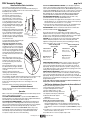
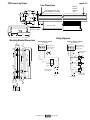
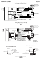
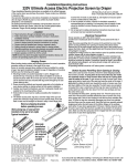
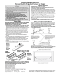
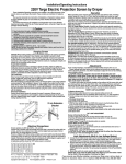
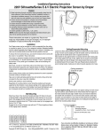
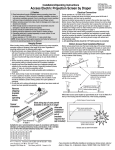
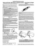
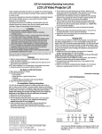
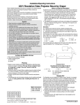
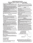
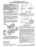
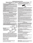
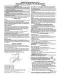
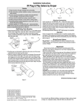
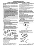
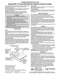
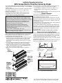
Installation/Operating Instructions
220V Access Electric Projection Screen by Draper
These Installation/Operating Instructions are available in the official language
of the country where you purchase the product. Please contact your distributor
to request a copy.
Vous pourriez demander les instructions d’installation et d’opération traduises
dans la langue officielle du pays ou vous achetez le produit. Veuillez
demander à votre distributeur.
Die Gebrauchsanweisung für Installation und Konstruktion sind in der
offiziellen Sprache des Landes, indem Sie das Produkt gekauft haben,
vorhanden. Fragen Sie die jeweilige Verkaufs-Abteilung.
Caution
➀ Read instructions through completely before proceeding; keep them
for future reference. Follow instructions carefully. Installation contrary to
instructions invalidates warranty. Care in mounting and correct operation
will mean long and satisfactory service from your Draper screen.
➁ Allow enough access to remove front cover should fabric become
damaged or should other service be required.
➂ Screen should be installed level (using a carpenter’s level).
➃ Nothing should be fastened to screen dowel or viewing surface
➄ Operating switch(es) is packed separately in screen carton. Do not
discard with packing material.
➅ Screen operates on 220V AC, 50 Hz., 1ph. current.
NOTE: Screen has been thoroughly inspected and tested at factory and
found to be operating properly prior to shipment.
Hanging Screen
When locating viewing surface and checking clearance for screen operation,
remember surface is centered in the length of the case. Regardless of
mounting method used, the following points apply:
➀ Mounting brackets are packed separately in carton. Engage each bracket
with top of housing as shown below and tighten set screws. A bracket
should be within 46 cm of each end of screen case. Brackets can be
removed and case mounted with lag screws through top of case (holes
drilled on site).
➁ Screen should be positively and securely supported so that vibration or
even abusive pulling on viewing surface will not weaken installation.
➂ Installer must insure that fasteners used are of adequate strength and
suitable for the mounting surface chosen. Supporting hardware (chains,
cables, rods, etc.) must be essentially vertical.
➃ Entire bottom of case must be readily accessible after installation is
complete.
Typical
Installation
Case dimensions
on page 3.
➄ Front, back and top of case must be straight—not forced to warp or bow.
➅ If case is painted on location, removal of roller/fabric assembly is
recommended prior to painting. If not removed, slot on bottom of case
should be shielded to protect viewing surface from paint splatters or
overspray.
➆ Do not seal unit in ceiling until electrical connections have been made and
screen has been operated successfully.
Electrical Connections
Screen operates on 220V AC, 50 Hz., 1 ph current.
Junction box is located just above the bottom access panel at left end of
screen (standard, right end may be specified).
Remove the bottom access panel for access to the junction box cover. (See
Bottom Access Panel Removal instructions below). Remove four (4) hex head
screws that secure the cover to the junction box to expose the terminal strip
per wiring diagram on page 4.
If optional low voltage control or video interface control is specified and factory
installed, please refer to wiring diagram on page 3.
Screen is shipped with internal wiring complete and control switch(es) fully
boxed. Wire to connect screen to switch(es) and switch(es) to power supply
should be furnished by installer. Connections should be made in accordance
with attached wiring diagram, and wiring should comply with national and
local electrical codes.
All operating switches should be “off” before power is connected.
Bottom Access Panel Installation/Removal
Bottom access panel hooks over the lower inside edge of the screen housing
and then is pivoted downward until the engagement brackets on each end of
the bottom panel click into place with the ball detents on each endcap. Make
sure bottom access panel clicks in place at each end of its length.
Remove bottom access panel by pushing up at each corner of panel adjacent
to slot in bottom of the housing.
With bottom access panel angled up approximately at 20° it can be lifted off of
the lip of the housing and then lowered out of the housing completely.
With bottom access panel
angled up approx. 20 degrees,
engage hook on the panel
with lip of the housing
Using the hook and lip as a pivot,
pull the panel downward until the
engagement brackets click into
place with the ball detent
on each endcap
Engagement bracket
(one on each end of the
bottom access panel)
Slots along
top of case
permit
brackets to
be set at an
angle
Alternate
Installation
(additional
set of
brackets
required)
Bottom flange of Access housing
Bottom access panel pushup
points for panel removal
Access case as seen from below
Copyright © 2007 Draper Inc.
Form Access220V_Inst07
Printed in U.S.A
If you encounter any difficulties installing or servicing your Access screen, call your
dealer or Draper, Inc., in Spiceland, Indiana, 765/987-7999 or fax 765/987-1689.
220V Access by Draper
page 2 of 4
Motorized Roller/Fabric Installation
The bottom access panel must be removed first.
The motor end mounting bracket has a metal bracket with snap ring for
accepting motor head. Back out the four set screws in bracket until they are
flush with top side of bracket.
To engage the motor end bracket flange
above the two channels in the top of
the screen housing, rotate the bracket
approximately 45° counterclockwise to
allow the top surface of the motor bracket
to rest flat against the top inside of the
housing. Rotating the bracket clockwise
until it is engaged with the channels, slide
it along the length of the housing against
the electrical junction box.
Engage the idler end bracket (rectangular
Retaining
mounting pad) in the same manner as the
clip
motor end bracket and slide it toward the
Motor roller
Washer
opposite end of the screen housing. Do
assembly
not tighten the set screws on this bracket
Idler end roller
until the roller/fabric assembly is installed,
mounting bracket
and centered in case.
Locate the black washer and retaining clip
attached to the instruction sheet.
Note: This step requires two people
to perform safely. Raise the roller/fabric
assembly up into the screen housing and
engage the head of the motor completely
into the motor mounting bracket, making
sure the snap ring engages with the motor
and that the limit switch adjusting knobs
are visible from the bottom of the screen
housing.
While supporting the idler end of the
roller, slide the idler end mounting bracket
toward the roller. Insert the roller pin
into the nylon bushing on the idler end
mounting bracket.
The roller idler pin needs to go through
the idler bracket far enough to allow the
washer and retaining clip to be reinstalled
on the pin.
Failure to replace the washer and
retaining clip could result in the separation
of the roller from the brackets.
The roller/fabric assembly and roller brackets may need to be slid left or right
in the mounting channel of case to center fabric within screen case.
Securely tighten the set screws on roller mounting brackets.
Connect the electrical plug from the motor to the mating socket on the
junction box.
Reinstall the bottom access panel as previously described.
Motorized Roller/Fabric Removal
Reverse the instructions above “Motorized Roller/Fabric Installation” for
removal of the unit.
Operation
When screen is first operated, be cautious! Cycle unit down and up several
times to confirm satisfactory operation.
220V SINGLE STATION CONTROL—3-position UP-OFF-DOWN switch
permits operation to be stopped at any point. Factory adjusted limit switches
automatically stop screen when fully down or fully up.
220V MULTIPLE STATION CONTROL—(Not CE Approved) Switches are
similar in appearance to 220V Single Station Control. Screen stops when
switch is released and may be restarted in either direction. Factory adjusted
limit switches stop screen automatically when fully up or fully down.
24V CONTROL—Three-button UP-STOP-DOWN switches stop at any
point desired, operate in any sequence. Factory adjusted limit switches
automatically stop screen when fully up or fully down. Installer should
incorporate an all-pole disconnect in the fixed wiring.
www.draperinc.com
220V & 12V VIDEO INTERFACE CONTROL—(Not CE Approved) Allows
screen to be controlled by a trigger signal—when the signal comes on, the
screen descends automatically. Two versions: Model VIC220 integrates screen
operation with a DRAPER video projector lift or a video projector or tuner with
a 220V switched outlet. Model VIC12 interfaces with a 12V switched outlet.
Both available with an override switch (VIC–OS), permitting independent
operation. VIC–OS not available with factory installed VIC220 & VIC12.
KEY OPERATED SWITCHING—(Not CE Approved) Two kinds of keyoperated switches are optionally available with this unit.
➀ The key-operated power supply switch controls power to the screen and
switches. When it is “off”, the switches will not operate screen. Key may be
removed from the switch in either “on” or “off” position.
➁ A three-position key switch permits the screen to be operated directly by
key. In this case, the screen’s operator must always have a key.
RS232/ETHERNET—Serial communication and network communication
optionally available with wall switches, RF or IR remote.
Adjustments
Screen has been factory set and should not normally require further
adjustment. However, if you desire to change the “up” and “down” stopping
positions, refer to drawing below and determine whether you need to adjust
the white socket or the yellow socket, and proceed as follows:
CAUTION: Be sure all switches are in “off” position before adjusting limit
switches. Always be prepared to shut screen off manually when new
adjustment is being tested. Screen may be severely damaged if viewing
surface is allowed to run too far up or too far down.
Fabric unrolling from
Fabric unrolling from
back of roller
front of roller
Left hand motor
Left hand motor
White Socket—Down
Yellow Socket—Up
White Socket—Up
Yellow Socket—Down
Right hand motor
White Socket—Up
Yellow Socket—Down
Audience
side
Audience
side
Right hand motor
White Socket—Down
Yellow Socket—Up
ADJUSTING WHITE SOCKET—White socket is located on the motor end
of screen roller and is accessible to a small flat screwdriver. Turning the
socket counterclockwise will allow the roller to run farther up or down (as
appropriate). Turning it clockwise will shorten operation, causing it to stop
sooner. One full revolution of the socket will alter the stopping position of the
viewing surface by approximately 32 mm.
ADJUSTING YELLOW SOCKET—Yellow socket is located on the motor
end of screen roller and is accessible to a small flat screwdriver. Turning the
socket counterclockwise will allow the roller to run farther up or down (as
appropriate). Turning it clockwise will cause the roller to stop sooner. One full
revolution of the socket will alter the stopping position of the viewing surface
by approximately 32 mm.
AT NO TIME SHOULD VIEWING SURFACE BE UNROLLED ENOUGH TO
EXPOSE ANY PART OF SCREEN ROLLER.
Tab-Tension Adjustment Procedure for Access/Series V
Draper’s Tab-Tensioning System is factoryset, and under normal circumstances will
not require field adjustment. If, however,
you notice wrinkles, waves, or other
indications that the tensioning cables need
to be adjusted, follow the procedure below.
Tensioning
Cable
Dowel
➀ Determine which side requires
Adjustment
Screw
adjustment.
➁ Secure dowel with one hand.
Caution: Do not touch or bend surface.
➂ Using Philips-head screwdriver, depress
spring-loaded adjustment screw (see diagram at right) and slowly turn
clockwise to tighten tension, or counterclockwise to loosen tension. The
screw adjusts in ¼ turn increments. Adjust only one increment (¼ turn) at
a time.
➃ If problem is not corrected, leave screen in position for 24 hours to allow
surface material to stretch into position.
➄ If problem still is not corrected, repeat steps 2 and 3.
(765) 987-7999
220V Access by Draper
page 3 of 4
Case Dimensions
Mounting brackets slide
left and right as needed.
22.86
cm
17.78
cm
16.83
cm
2.22
cm
2.22
cm
5.4
slot
L
Series E or M
Access
L
Series E 17.8 cm
Series V Varies
Series V
120mm
54mm
Wiring Diagrams
Multiple Station Control
CE Approved
Not CE Approved
6.35
mm
Single Station Control
Terminal strip in
junction box at left
end of screen
Terminal strip in
junction box at left
end of screen
4.8
mm
28.6
mm
Mounting Bracket Dimensions
228.6
mm
Control
switch
Neutral
230V, PE
50 Hz.
R3.2
mm
6.35
mm
35
mm
www.draperinc.com
Blue
Black
Hot
8
mm
38
mm
Red
230V, 50 Hz.
12.7
mm
R 6.35
3.2 mm
mm
Blue
Black
Neutral
122.2
mm
Black
Red
Dashed wiring
by electrician
9.5
mm
Blue
Red
197
mm
4.8
mm
114
mm
32
mm
8
mm
Cap off with wire
nut & tape
L1
30mm
2.54
cm
20.3 cm
Engagement bracket (one on each end
of the bottom access panel) clicks into
place with the ball detent on each endcap
Mounting
hardware
supplied by
others
(765) 987-7999
Dashed wiring
by electrician
220V Access by Draper
page 4 of 4
Low Voltage and Remote Control
Terminal strip in
junction box at left
end of screen
Hot
Neutral
Red-to screen (directional)
Brown-to screen (directional)
White-Common to screen, 230V AC
Black-to 230V AC
Yellow-to 230V AC
Green-Ground
Dashed wiring by electrician
Low voltage wiring by others
Eye Port for IR Eye, RF Receiver or LED
Switch For more than one of these,
a splitter is required.
3 Button Wall Switch
DOWN - Black
COM - White
UP - Red
All-Pole Disconnect
by Others
STOP
STOP
Aux Port for connecting additional
LVC-III modules (up to six totalconnect from Aux to Eye).
230V, 50 Hz.
Control
Switches
24v DC
Wiring Diagrams (continued)
MC1
Terminal strip in
junction box at left
end of screen
Hot
Neutral
Program LED
Red-to Screen (directional)
Black-to Screen (directional)
Blue-Common
Brown-Hot to 230V AC
Green/Yellow-Ground
Low Voltage Wiring by others
AC Wiring by electrician
Fuse
RS232 Data FROM Control System
RS232 Data TO Control System
Signal Ground & Manual Switch Common
Manual Switch Down
Manual Switch Up
Eye Port for IR Eye. For RF Receiver
or LED Wall Switch, a Splitter and a
Power Supply is required. Plug RF
Receiver or LED Wall Switch and
Power Supply into splitter, then run
cable from Splitter to MC1 Eye Port.
MC1
All-Pole Disconnect
by Others
STOP
STOP
230V, 50 Hz.
Control
Switches
24v DC
See separate Serial CommunicationRS232 Instruction
sheet for enabling
RS232 with the MC1.
Built-in Video Interface Control
Built-in Low Voltage Control
Junction box at
left end of screen
Junction box at
left end of screen
Internal screen wiring
Internal screen wiring
Black (Hot)
220 VAC supply L1
Blue (Neutral)
N
Blue (Neutral)
N
Green/Yellow (Ground)
Black (Hot)
220 VAC supply L1
Green/Yellow (Ground)
Trigger signal
VIC220 (220 VAC, white cord & plug)
VIC12 (12 VDC, brown & orange leads)
Dashed wiring
by electrician
Dashed wiring
by electrician
www.draperinc.com
(765) 987-7999