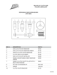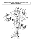
1
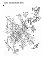
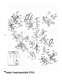
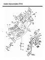
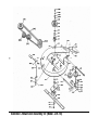
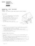
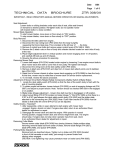
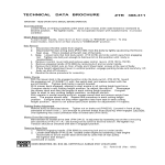
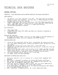
TECHNICAL
DATA
BROCHURE
ZTR
310
.IMPORTANT - READ OPERATOR'S MANUAL BEFORE OPERATION.
Seat Adjustment
Loosen Bolts on sliding brackets under each side of seat, slide seat forward or rearward to desired position.
Re-tighten bolts. Do not operate mower with bracket bolts in a loose condition.
Mower Blade Operation
To start mower blades, move lever on floor slowly to "ENGAGE" position. To stop mower blades,
move lever on floor slowly to "DISENGAGE" position.
Body Removal
1. Disconnect throttle cable from engine.
2. Disconnect the rear wiring loom (P/N 4109) from the body by lightly squeezing the Econo-Seal plug. This
Is located at the left rear of the body.
3. Note: Loosen bolts that hold body switch (P/N 4079) and slide switch away from engaging rod. Tighten one
bolt just enough to hold switch 1n this position until body is reassembled.
4. Remove 4 control lever bolts and remove upper control levers (P/N 1689 i 1690).
5. Remove engaging handle (P/N 6089) by removing bolt and nut under handle.
6. Remove the 2 attach nuts on floor of body and 2 sheet metal screws at the rear of body.
7. Place height adjustment lever i n vertical position, engage parking brake and carefully lift body up and
off chassis.
8. Reverse the above procedure for assembly.
Safety Checks
With the mower deck in the engaged position slide the body switch (P/N 4079) toward
the engaging rod (P/N 6038)
until the switch leaf just makes contact with the
s w i t c h button. Tighten both bolts 1n switch bracket.
with mower deck engaged, attempt to start engine in all cutting height positions.
if engine starts in any cutting height position, re-adjust the switch. Disengage
the mower deck and start the engine In each cutting height position. If engine
fails to start in any cutting height position, re-adjust switch.
with operator in normal mowing position, engage mower deck and remove weight from
seat. The engine should stop. Repeat this procedure in each cutting height
position. If engine does not stop when operator rises from seat in each cutting
height position, return to an authorized Dixon dealer for adjustment or repairs.
Parking Brake Adjustment
Remove body as described above. Tighten nut on brake rod (P/N2533) (Located 1n front of the transaxle on
each side.), just enough to prevent brake from slipping when engaged. CAUTION: Over tightening may
cause premature wear on brake band (P/N 5085).
Mower Drive Belt Adjustment
Belt tension for mower drive belt (P/N 2412) is adjusted by loosening nut on the connecting arm assembly
(P/N 2148) and turning bolt to achieve desired tension. Re-tighten nut. Tension should be checked with
belt 1n engaged position.
Removing Mower Deck
1. Remove engaging handle (P/N 6089) by removing bolt and n ut under handle.
2. Loosen belt keeper (P/N 2234) located under engine by loosening 2 rear engine mount bolts to allow mower
deck drive belt to come free of rear pulley. Re-tighten belt keeper.
3. Remove 4 attach pins (P/N 6107) and clips fro* 4 mower deck attach points and 2 stabilizer bars (P/N 6159).
4. Raise front of mower chassis to allow mower deck engaging rod (P/N 6038) to clear the chassis. At this time,
mower may be rolled free of mower deck for s e r v i c e and/or replacement.
5. To re-install, reverse the above procedure.
Removing Hower Cutter Blade
Secure mower cutter blade (P/N 2406) from turning (observe blade position when removing) remove blade bolt
from center of blade.
DIXON INDUSTRIES, INC. BOX 494 COFFEYVILLE, KANSAS 67337-0494 (316) 251-2000
P/N 8536 (H/83)
PARTS LIST FOR 2TR 310
PART #
1015
1022
1030
1039
1046
1108
1109
1110
1140
1507
1536
1540
1544
1636
1647
1654
1655
1657
1667
1678
1679
1682
1689
1690
2077
2100
2105
2127
2134
2147
2148
2149
2154
2155
2159
2164
2166
2172
2179
2180
2185
2197
2203
2204
2234
2237
2238
2246
2249
2402
2406
2408
2411
2412
2413
2414
2417
2422
2452
2460
2463
2465
2466
2468
2469
2475
2504
2509
2514
2515
2526
2527
2529
2532
2533
2534
2536
2538
2542
2543
2612
2626
2640
NAME
Caster
Caster Wheel & Tire
Upper Lift Link
Lower Lift Link
Lift Tule Short
Tire - Front Wheel
Inner Tule-Front Wheel
Caster Axle Bushing
Caster Wheel Bearing
Wheel/Deck Hub Bearing
Chain Connecting Link
Engine Shaft Key
Bellcrank
Bellcrank Kit
Control Pin
Transaxle Idler Bracket
Transaxle Idler Pulley
Transaxle Idler Spring
Lower Control Lever
Flat Idler Pulley
Chain Tensioner Bracket
Chain Tensioner "L" Rod
Upper Control Lever w/grip L
Upper Control Lever w/grip R
Walking Beam
Bumper
Bumper Pad
Quadrant Spring
Lift Handle
Connecting Arm Bracket
Connecting Arm Assembly
Torque Rod
Hub Pulley Spacer
Hub Bearing Spacer
Engaging Idler Spacer
Support Sprocket Spacer
Pivot Bolt
Swivel Fitting
Switch Bracket - Body
Switch Bracket - Switch Sect
Body
Frame
Wheel Hub Assembly
Wheel Hub
Belt Keeper
Tie Bar Assembly
Tie Bar
Battery Box
Mounting Bar
Rear Wheel & Tire
30" Mower Blade
Drive Chain Assembly
V - Pulley
Deck Drive Belt
V - Idler Pulley
Engaging Idler Bushing
Control Rod Assembly
Name Decal
Engaing Ikler Bushing
Parking Brake Decal
Seat (S/N 5746 to Date)
Rear Tire (16x6.50-8.00)
Rear Rim (16x6.50-8.00)
Double Engine Pulley
Transaxle Drive Belt
Control Rod
Rront Tube
Support Shaft
Torque Rod Stiffener R
Torque Rod Stiffener L
Brake Link L
Brake Link R
Rear Tube
Spacer 5/16 x .203
Brake Rod
Brake Handle
Brake Arm
Brake Arm Stop
Support Casting L
Support Casting R
Engaging Idler
Deflector Sheet
Mower Deck Hub Assy
PART#
2641
2642
2645
2647
2648
2668
2678
2823
3000
3003
3005
3007
3008
3009
3010
3012
3013
3014
3019
3020
3023
3029
3031
3032
3033
3035
3036
3046
3047
3050
3051
3052
3053
3054
3056
3057
3058
3060
3061
3063
3065
3066
3067
3072
3074
3076
3078
3080
3081
3082
3083
3088
3090
3091
3092
3093
3098
3099
3100
3101
3103
3105
3107
3116
3118
3119
3120
3124
3128
3129
3133
3134
3136
3138
3156
3157
3158
3159
3161
3176
3180
3181
NAME
Mower Deck Hub Sub Assy
Mower Deck Hub
Blade Shaft
Blade Washer
Deck Hub Key
Stiffener for Deck
Engaging Rod w/brake
Oil Drain Assembly
5/16-24 UNC Hex Locknut
5/16-18 UNH x 1 ½ HH Bolt
5/16-18 UNH HH Bolt
¼ - 20 UNC Hex Nut
¼ x 3/4 Flatwasher
5/16-18 x 1 3/4 HH Bolt Gr. 5
½ x 2 ¼ Rd. Hd. Nut
3/8-16 UNC Hex Nut
½ - 13 UNC Hex Locknut
¼ - 20 UNC x 3/4 HH Bolt Gr. 2
5/16 Helical Lockwasher
5/16 Std. Flatwasher
¼ Helical Lockwasher
Front Gromment
5/16 - 18 UNC Acorn Nut
½ Helical Lockwasher
½ SAE Flatwasher
½ - 13 UNC Jam Locknut
3/8 -16 UNC Hex Locknut
3/8 -16 UNC x 2 HH Bolt
3/8 - 24 UNF Hex Locknut
# 10 - 24 UNC Hex Locknut
# 10 -24 UNC x 1 3/4 Soc. Hd. Bolt
3/32 x 3/4 Cotter Pin
# 10 x 1 HH SM Screw
3/16 x 1 Roll Pin
5/16 Fender Washer
1/8 x 2 Cotter Pin
3/16 x 3/4 Roll Pin
5/16 x 18 UNC x 3/8 Socket Set Screw
# 10 - 24 UNC x 1 ¼ Rd. Hd. Screw
3/8 Helical Lockwasher
3/16 Std Flatwasher
# 10 - 24 UNC x 1 Rd. Hd. Screw
1/8 x 1 3/4 Hair Pin Cotter
5/16 - 24 UNF Hex Jam Nut
3/8 - 24 UNF Hex Jam Nut
3/8 - 24 UNF Hex Nut
5/16 -18 UNC Hex Locknut
# 6 -32 x 1 Rd Hd Screw
# 6 -32 UNC Hex Nut
# 6 - Lockwasher
¼ - 20 UNC x ½ Rd. Hd. Bolt
¼ -20 x 1 HH Bolt Gr. 5
½ -20 UNF x 1 ¼ HH Bolt Gr. 2
½ - 20 UNC Hex Lug Nut
½ -20 UNF x 1 ¼ HH Blade Bolt Gr. 5
5/16 -18 UNC HH Bolt
5/16 -18 x 3 HH Bolt
7/16 - 20 UNF x 3/4 HH Bolt Gr. 5
7/16 HD Flatwasher
7/16 Lockwasher - Helical
3/8 -24 x 1 HH Bolt Gr. 5
¼ x 1 ¼ HD Spirol Pin
¼ x 1 ½ HD Spirol Pin
5/16 - 18 UNC x 1 Carriage Bolt
Disc Spring
Retaining Ring
Nylon Showlder Bushing
5/16 - 18 UNC x 6 HH Bolt
7/16 - 14 UNC Hex Jam Nut
Plastic Tube Closure
# 8 - 32 x ½ Tr. 3 Screw
¼ - 28 x ¼ Soc. Set Screw
Pop Rivet
Std. Steel Burr. 103
5/16 - 18 UNC 2A x 1.125 Long HH Bolt
# 8 - 32 TR 3 x ½ Whiz Lockhead Sc.
5/16 -18 UNC Hex Locknut Gr. 8
Disc Spring
5/16 - 24 UNF Nut LH Thread
Snap Bushing
¼ -20 Hex Locknut
Woodruff Key #605
2
PART #
3182
3187
3188
3189
3194
3197
3198
3199
3203
3401
3402
3500
3502
3503
3504
3507
3508
3511
3521
3531
3532
3536
3577
3578
3585
3588
3598
3599
3603
4009
4013
4047
4075
4079
4092
4109
4115
4120
4124
4148
4162
4197
4201
4204
4209
4211
4215
4216
4217
4236
5005
5007
5012
5015
5018
5019
5021
5028
5036
5046
5047
5050
5079
5084
5085
5103
5106
5109
5110
5111
5112
5128
5129
5133
6059
6089
6107
6159
6185
8502
8503
NAME
Flip Lock Bushing
# 10 - 32 Hex Nut
# 10 Ex. Tooth Lockwasher
½ - 13 x 5 ½ Carriage Bolt
Face Nut 5/8 - 32
5/8 - 11 Jam Lock Nut
¼ - 20 Wing Nut w/ny
5/16 -18 x 2 ¼ HH Bolt
3/8 SAE Washer
Tube
Bronze Bushing
Ball Joint / Control Rod RH Thread
Hand Grip
Ball Joint / Control Rod LH Thread
Bouble Ball Joint
Floor Pad - Long
floor Pad - Short
Adhesive Bumper Pad
Engaging Cam Mount Bushing
Decal - Operating Insruction
Decal - Blade Drive
Warning Label - Danger
Battery Cover
Nylon Bushing
Decal - Cutting Height
Dical - Ignition Switch
Model Decal
Iso Mount
Iso Insert
Wire Clip
Wire Tie
Seat Switch
10 Amp Fuse
Body Switch
Fuse Holder
Real Wiring Loom
Wiring Kit
Body Wiring Loom
Solenoid
Seat Angle
Butt Connector
Ignition Switch
Switch Key for 4197
Flex Guard Wiring Cover
Throttle Cable
Solenoid Starter Cable
Solenoid / Battery Ca ble
Battery Ground Cable
Battery
Red Wire W / Terminal
Discup
Cone Frame
Cradle Shaft
Sprocker - 24 T
Sprocker 9T - Narrow
Transaxle Chain
Sprocket 9T - Wide
Transaxle Bearing
Pivot Spring
Positive Neutral Rod
Positive Neutral Spring
Positive Neutral Kit
HD Transaxle Pulley
Brake Drum
Brake Band
Eye Bolt
Cone Frame Assembly
Molded Cone / Keyed
Cone Frame Shaft
Sleeve (fits 5110)
Key Sq. 3/16 x 1 ½ (fit 5110)
Cradle L
Cradle R
Cradle Spring
Flat Idler Pulley
Engaging Handle
Deck Pin
Stabilizer Arm
Engaging Cam
Caster Axle Kit
Front Rim
Illustration - Chassis Assembly (Model ZTR 310)
3
4
Illustration - Transaxle Assembly (Model ZTR 310)
Illustration - Body Assembly (Model ZTR 310)
tn
6
Illustration – Mower Deck Assembly 30” (Model ZTR 310)