1
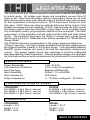
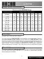
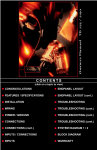
TD 2200 / 225A
Owners Manual
CONTENTS
(click on a topic to view)
CONGRATULATIONS
ENDPANEL LAYOUT
FEATURES / SPECIFICATIONS
ENDPANEL LAYOUT (cont.)
INSTALLATION
TROUBLESHOOTING
WIRING
TROUBLESHOOTING (cont.)
POWER / GROUND
TROUBLESHOOTING (cont.)
CONNECTIONS
TROUBLESHOOTING (cont.)
CONNECTIONS (cont.)
SYSTEM DIAGRAM 1 / 2
INPUTS / CONNECTIONS
BLOCK DIAGRAM
INPUTS
WARRANTY
Thank you for choosing TUBE DRIVER. Tube Drivers musicality and absolute sonic
transparency allow accurate reproduction of recorded music enabling you to hear as well as
feel the music the way the artist intended. These handcrafted amplifiers feature full differential
“front ends” based upon a true instrumentation amplifier topology. Tube Drivers utilize only
the highest quality Svetlana tubes in our unique configurations. All of the internal amplifier
stages have been designed to have ultra-wide bandwidth together with a high degree of
linearity. The tubes used in these amplifiers provide both voltage gain and current gain where
they are connected in Cascode and Cathode Follower configurations. D.C. servos are used
to control any D.C. offset. These servos are critically positioned in the circuit so that not only
is D.C. offset eliminated but also any subtle differences between tubes are internally
compensated. These tube stages are then connected to a high current BiPolar output stage
that uses the same audiophile quality Sanken output devices featured in the PrecisionPower
2500F1.The output stages receive their power from a highly regulated D.C. power supply
which enhances their performance significantly. Very little negative feedback is used. Low
feedback designs have greatly improved sound quality having an extremely warm and open
sound with enhanced musicality consistent with only the highest quality home tube amplifiers.
S ervice
Do not attempt to service TUBE DRIVER products yourself.
Performing exploratory surgery on your audio equipment yourself
will void the warranty. Many parts of your TUBE DRIVER gear
are custom built to our specifications. Our factory parts are not
made available to anyone else nor are they for sale. Our goal
is to make sure that your TUBE DRIVER product will always
sound as good as the day it was purchased. Contact your
authorized TUBE DRIVER dealer about obtaining any warranty
service through TUBE DRIVER.(See Warranty insde back cover)
FOR YOUR RECORDS
M o d e l
Serial Number
Purchase Date
C aution!
The extended use of a high powered audio system may
result in hearing loss or damage. While TUBE DRIVER
systems are capable of "Concer t Level" volumes with
incredible accuracy, they are also designed for you to
enjoy at more reasonable levels all of the sonic subtleties
created by musicians. Please observe all local sound
ordinances.
BACK TO CONTENTS
The TD2200PRO and TD225A amplifiers represent a radical new approach
to mobile audio. All voltage gain stages are completely vacuum tube-10
tubes in all! Other than the output devices themselves, there are no solid
state devices in the audio path. Specific types of Svetlana tubes were chosen
for their application in the audio section. 6N1P tubes were chosen for their
high gain. 6SN7 tubes are ideal as cathode followers at the output of the
preamp increasing current capability. 6L6GC tubes provide the high current
and power used to drive the solid state output stage. In the coupling stages
only audiophile quality polypropylene capacitors are employed. The input
connections of the amplifiers include balanced Mini-DIN and Gold plated
RCAs. The amplifiers also have the ability to accept high voltage inputs
with the aid of a built in 12dB attenuator and be operated in a “Mixed Mono/
Stereo Mode”.
The TD225A features increased bias in the output stage providing true
“Class A” operation. The high voltages available from the gain stages ensure
the highest possible linearity in the output signal. Fully regulated adaptive
MosFET power supplies are used to provide the necessary voltages and
current. The power supply circuits are optimized to limit the substantial
heat generated by Class A operation. Class A amplifier designs are regarded
by most high end home audio companies as the benchmark for sound quality.
Specifications
Power Bandwidth:
Total Harmonic Distortion:
Input Topology:
Input Sensitivity:
Input Impedance:
Output Impedance:
5 Hz -50 KHz
0.2% or less (A-weighted)
Balanced Differential
500mV - 12 volts RMS
10K Ohms
2 - 16 Ohms, bridged 4 - 32 Ohms
Continuous Output Power
TD2200PRO
TD225A
200 WRMS x 2 @ 4 Ohms / channel
400 WRMS x 2 @ 2 Ohms / channel
800 WRMS x 1 @ 4 Ohms / channel
25 WRMS x 2 @ 4 Ohms / channel
50 WRMS x 2 @ 2 Ohms / channel
100 WRMS x 1 @ 4 Ohms / channel
Dimensions
TD2200PRO
Length = 33.4
Height = 3.2”
Width = 9.25”
TD225A
Length = 33.4”
Height = 3.2”
Width = 9.25”
1
BACK TO CONTENTS
To o l s / P a r t s N e e d e d f o r I n s t a l l a t i o n
(not supplied)
Small flat blade screwdriver
Phillips screwdriver (#2 or medium sized)
Wire cutters
Wire strippers
4 – #6 round head screws, and 1 – #8 sheet metal screw
(or nut, bolt, and star washer)
2 – Ring connectors (large enough to accommodate your method of grounding)
In-line fuse or circuit breaker — see fuse requirements below
Power and groundwire — see Power Wire Calculator on the next page
Speaker wire — 16 gauge or larger
Grommets (sized to work with the power wire you plan to use in your installation)
Tube of silicone sealant
Fuse Requirements
R e c o m m e n d e d F u s e R a t i n g for TD2200 i s 100 A m p s
R e c o m m e n d e d F u s e R a t i n g for TD225A is 100 A m p s
You will need to install an in-line fuse or circuit breaker in the power wire
within 18” of the battery. This fuse or circuit breaker protects your vehicle
from fire in case the power wire shorts to the vehicle body. If you are only using
one amplifier, use the recommended fuse rating. If you are using more than one
amplifier, add up the fuse ratings for all amplifiers, and use this sum for your main
fuse or circuit breaker. Use a power distribution block or fuse near your amplifiers
with the appropriate fuse for each individual power wire.
The information below is a basic formula you can use to determine approximate
current draw. A 50% amplifier efficiency rating is used as an average. This formula
is only a guideline. Using wire of a larger gauge can only improve the current transfer
of your system. Do not use smaller gauge wire.
Total 4-Ohm rated RMS output x 2 = Total Input Wattage
Total Input Wattage/Supply Voltage = Current Draw (in Amps)
Example: A TD275 has 2 channels at 75 watts per channel RMS into 4-Ohms
(75 x2 =150). You would use the formula below:
150W x 2 = 300W/12.5V = 24 Amps Total Current Draw
2
BACK TO CONTENTS
Power Wire Calculator
Recommended MINIMUM Gauge
Total Current Draw
(in Amps)
Length of Wire to Run (in Feet)
<3
4-7
7 - 10 10 - 13 13-16
16-19
19-22
22-28
0 - 20
14
12
12
10
10
8
8
8
20 - 35
12
10
8
8
6
6
8
4
35 - 50
10
8
8
6
6
4
4
4
50 - 65
8
8
6
4
4
4
4
2
65 - 85
6
6
4
4
2
2
2
0
85 - 105
6
6
4
2
2
2
2
0
105 - 125
4
4
4
2
2
0
0
0
125 - 150
2
2
2
2
0
0
0
0
Warning!
Amplifiers Generate Heat!
You can mount the TUBE DRIVER in any position, even upside-down. However,
you must maintain proper airflow. Do not install your TUBE DRIVER under
carpets or enclose it behind airtight panels. In trunk-mounted applications, be sure
to provide venting for air circulation. Let the amplifier breathe. The TD225A is a
class A design. It needs to dissipate a high amount of heat during its operation.
Without adequate air circulation, your Tube Driver will turn itself down to protect
Mounting
You need to mount your TUBE DRIVER securely in your vehicle to prevent damage.
You may mount the system right-side up, on its side, or upside-down, provided
there is adequate ventilation.
3
BACK TO CONTENTS
Warning!
To prevent a short to ground, disconnect the negative (-) terminal of the system’s
battery before you begin. If the power cable shorts to ground, current will continue
to flow until the short is opened, the main fuse blows, the battery explodes, or the
wire melts.
R e connec t th e te rm ina l only a f t e r you m ake al l co n n ecti o n s.
Grounding
Your TUBEDRIVER is designed to operate from a car’s positive 12 volt, negative
ground electrical system. The ground wire should be the same gauge as the power
wire indicated in the chart.
The main power cable should run from the amplifier location, through or under the
vehicle, to the battery. You must use a grommet wherever the cable passes through
a steel panel to prevent an eventual short to ground.
The ground connection is the most important part of any installation. If the
connections are poor and/or the resistance is high, the resulting drops in voltage
will rob you of amplifier power and may allow noise to enter your system. Your new
Tube Driver features a fully regulated power supply. It will make full power even if
the voltage changes. It will draw more current at lower voltages to make that power.
Lower voltage and high cable resistance means more total current draw. Using a
digital multimeter (DMM), try to get cable resistance as low as possible. If resistance
is too high, use a larger gauge wire. Try to ground your system to a single point in
the vehicle. In larger systems, use distribution blocks and run both power and ground
cables directly to the system battery.
R e m o t e Tu r n - o n
IMPORTANT! Your new Tube Driver is equipped with our unique tube warm-up
circuit. When your system is turned on, The LED labeled “WARM UP” will
illuminate and full power is applied to the tube heaters for approx. 35 seconds.
The internal fan will then turn on and two seconds later the amp outputs will
be switched on. The system will then play as normal.
You must connect a wire to the remote (REM) terminal (located in the speaker
terminal plug) of your amplifier to power on your TUBEDRIVER . The source unit
normally provides a remote amp turn-on or power antenna lead that provides this
+12 volts when you turn on the unit.
• Run a wire from the chosen turn-on lead to the REM connection
of your TUBEDRIVER (See Endpanel Layout: Page 10)
• Tighten the connection
4
BACK TO CONTENTS
Speaker Connections
Follow these simple instructions and refer to the diagram below to
make your speaker connections:
• Using at least 16 gauge wire, run wire from the speakers to the
amplifier(s) using the same precautions that you followed for
running the power, ground, and remote wires
• Cut off excess wire
• Use wire strippers to strip 1/4 inch of insulation at the end of
the wires
• Attach the speaker wires to the amplifier’s POWERLOCK connector and plug
it in
Speaker PowerLock Connector
Right Speaker negative
Right Speaker positive
Remote turn on
Left Speaker positive
Powerlock connector
Left Speaker negative
5
BACK TO CONTENTS
Bridging
All multi-channel T UBE DRIV E RS are capable of being bridged into a 4Ohm mono output without switches or bridging modules.
You can achieve this mono channel by using the left positive (+) speaker
connection and the right negative (-) speaker connection. (Refer to the end
panel drawing on the next page.)
Note: Total bridged impedance of less than 4-ohms may trigger the
protection circuitry causing reduced output and may eventually
damage your amplifier.
Mixed Mono Output
You can operate each pair of channels in both stereo and mono (3 channel
or tri-mode) at the same time by using highpass filters (bass blockers) on
the higher frequency stereo channels, and a lowpass filter (coil) on the
subwoofers. The frequencies of the chosen highpass and lowpass filters
must not overlap (allow the mids and highs to play the same music as the
subs) or the impedance the amplifier sees at those frequencies will be cut in
half possibly causing it to turn down.
FRONT
L- L+
R+RHighpass
Filter
Highpass
Filter
Tweeter
Tweeter
MidRange
MidRange
Bandpass
Filter
Bandpass
Filter
Low pass
filter
Sub
6
BACK TO CONTENTS
Input Jacks
Your TUBE DRIVER includes both RCA and Mini-DIN (balanced) inputs. The
supplied RCA connections allow you to use TUBE DRIVER with other brands
of audio gear. Our Differential RCA inputs provide a dramatic improvement in
noise reduction over standard RCA input types. Our fully balanced Mini-DIN
connection system features high signal voltage capability and the highest
possible sound quality. A single cable for 2 channels also simplifies installation.
Cables from the source unit, non-powered equalizer, or crossover go here.
Balanced Inputs
Standard Coaxial RCA Cables
Standard coaxial RCA cables utilize two connections: a center wire (signal
positive) attached to the center pin of the RCA connector along with a braided
outer conductor (signal negative) connected to the outer ring of the RCA
connector. This design almost always allows radiated noise to enter the system,
since the signal is not well protected.
(+) Positive
(-) Negative
B a l a n c e d Mini-DIN Cable
Balanced Mini-Din connections use six pins and one grounding ring. Pins 1 and
2 are open connections, normally they would carry your remote turn on voltage.
Pins 3/4 and 5/6 are a pair of twisted conductors for the music signal. The twisting
of the inner wires rejects or eliminates radiated noise by more than 30 dB. The
inner pair of wires are then protected by an outer shield connected to Pin 1. This
means the music signals can be kept as far away as possible from the power
and chassis ground paths of other circuitry, allowing the transmission of pure
music between points while protecting it from noise generating equipment and
wiring present in the vehicle. The diagram below shows the pin configuration
for the Mini-Din connections.
5
6
3
4
7
BACK TO CONTENTS
Input Gain Control
There is an Input Gain Control located on the end panel under the RCA
input jacks. This is not a volume control! This control matches the output
signal voltage of the source unit to the amplifier inputs.
By turning the control clockwise (to the right), the inputs of the amplifier
become more sensitive and will allow a weak signal of approximately 1/2
volt to drive the amplifier to full power. At the same time, while an amplifier
with its level control at maximum is able to drive a weak signal, it also picks
up and amplifies any noises lurking in the background, such as a brake light
pop, alternator whine, or ignition tick.
Increasing the signal voltage to the amplifier by using a high output source
unit (or a TUBE DRIVER LD-3) makes the music much louder. By turning
the level control counterclockwise (to the left), the amp inputs will be less
sensitive. The amp will reproduce music at full power while making any
noise floor insignificant. Your TUBEDRIV E R accepts signal levels of up to
12 volts RMS.
Setting Input Gain
1. Set the Input Gain Control to just above the lowest setting.
2. Turn the master volume on the source unit or pre-amp to almost full
volume.
3. With music playing, slowly increase each Input Gain Control until you
hear distortion. Turn down the Gain Control until the distortion stops.
8
BACK TO CONTENTS
Power Side
1. POWER
A red light indicates that the amplifiier is turned on (After warm-up sequence).
2. WARM UP
A red light indicated that the tubes are warming up. (Refer to Pg. 4; Remote Turn-on)
3. POWER / GROUND
After you have securely connected your power and ground wires, plug in the
connector here.
HANDCRAFTED IN THE USA
By Precision Power
POWER CONNECT
POWER
1
WA R M U P
2
3
9
BACK TO CONTENTS
Input/Control Side
1. SPEAKER OUTPUTS/REMOTE(Turn on)
After connecting remote and speaker wires plug in the connector here.
2. GAIN CONTROL
Use this control to match the output level of the head unit to the outputs of the amplifier
3. BALANCED INPUT
Plug in the mini-din output from the LDX-33 crossover, LD-3 line driver, or other
balanced source here.
4. -12dB
For use with high level inputs (4V up to 12V). Push this switch in to attenuate the
input by 12dB.
1
2
3
4
6
5
HANDCRAFTED IN THE USA
By Precision Power
BALANCED
INPUT
SPEAKER OUTPUTS
L- L+ REM R+ R-
GAIN
INPUTS
DIN/RCA
-12dB
L
R
7
5. BALANCED / RCA
This switch is used to select between the unbalanced RCA inputs or the balanced
MINI-DIN inputs.
6. INPUTS
Plug in the RCA outputs from your head unit here.
7. COOLING VENTS
10
BACK TO CONTENTS
No Sound
Is the WARM UP LED illuminated?
YES
NO
Do you have 12V at the amplifier’s
connections?
The warm up cycle can take up to
40 sec., Is there sound after that?
YES
YES
NO
Is there
signal on the
RCA’s?
NO
Does the amp
remote (REM)
have 12V?
You’re done
YES
YES
Contact your
dealer
Check main
system fuse.
Did that work?
YES
You’re done
Check all
connections.
Repair as
needed
NO
Trace back the amp
remote to your source
unit. Repair as needed
NO
Contact your
dealer
A m p l i f i e r Tu r n i n g D o w n a t N o r m a l Vo l u m e
Turn the system off, wait approx. 5 min., then turn
the system back on. Listen for awhile. Did it work?
YES
NO
Check speaker wires for shorts or other
damage and correct as needed.
Did that fix the problem?
If sound is heard, the Amp may have
thermally turned down. Check for proper
air flow and correct as needed. You’re
done.
YES
NO
You’re done
Check voltage supply to
ensure sufficient voltage.
Did that work?
YES
NO
You’re done
Contact your
dealer
11
BACK TO CONTENTS
No Sound in One Channel
Check the pre-amp (RCA/Mini-Din) cables for open connections and make
corrections. Did you find open connections?
NO
YES
You’re done
Reverse the left and right inputs.
SOUND IS NOW IN...
Opposite Channel
Same Channel
Problem is further up the signal path.
Reconnect RCA’s to amp as normal.
Reverse RCA inputs at crossover.
Problem is in the speaker or speaker
wire of the silent channel. Check
speaker leads for pinched, shorted, or
open connections.
SOUND IS NOW IN...
Same Channel
Opposite Channel
Problem is in the crossover. Contact
your dealer.
Reverse RCA outouts of head unit
SOUND IS NOW IN...
Opposite Channel
Same Channel
Problem is in the head unit
Problem is in the RCA cables.
A m p l i f i e r Tu r n i n g D o w n a t H i g h Vo l u m e
Check speaker cables for shorts. Check for
excessively low speaker impedance. Fixed?
YES
NO
You’re done
Check voltage supply to ensure sufficient voltage is
being delivered. Is amp getting enough air to cool
off? Did that solve the problem?
NO
I f using passive crossovers, are the
YES
You’re done
connections correct?
NO
YES
Voltage at amp may be
dropping below minimum
limits.
Power output of amp may exceed
power handling of parts. Upgrade as
needed.
12
BACK TO CONTENTS
Noises While the Engine is On
Alternator whine:
This noise changes in frequency with engine RPM. Check for:
. Excessive input level
. High resistance in cabling or corroded and/or loose connections
. Polarity of the input cables
If the problem persists, check the whines and pops checklist below.
Ticks/buzz:
This noise should go faster and slower with engine RPM, but not really change in
frequency. This is due to the ignition or the fuel pump.
. Try moving the input cables to avoid contact with the fuel pump or wiring
If the problem persists, check the whines and pops checklist below.
Accessory pop:
This popping noise occurs as the result of turn signals, brake lights, etc. You can
try:
. Moving the cables to avoid contact with the wires for the accessories
. Relocating various ground connections
Whines and pops:
If you have a combination of noises, or if one or more of the problems listed above
persists despite efforts to stop the problem, the noise may be caused by one or
more of the following problems:
. Excessively high input level setting on the amplifier
. Poor or open shielding, extra long cables or corroded input cables
. Bad connections
. Bad (or high resistance) system ground
. Reversed polarity on audio signal cables
. Poor quality source unit
13
BACK TO CONTENTS
Noises While the Engine is On or Off
System hiss:
System hiss is a white noise that occurs even when the engine is off. It is
usually due to excessively high gain settings. If the hiss is still audible
when you disconnect the input cables from the amplifier, check the input
level on the amplifier. If the hiss disappears when you remove the input
cable, it may be a poor quality source unit, components between the
amplifier and the source unit, or poor level settings.
Distortion:
Distortion is garbled sounding music. This can often be caused by a shorted
speaker wire. Symptoms of this include no sound in one channel and severe
distortion in the other. Use the following guide to help you find the source of
distortion.
Is there audible distortion at all of
the amplifier outputs?
YES
NO
Try reducing the input level
controls.
Check each side of the amplifier
independently to see if the
distortion is only on one channel.
Is that the case?
NO
YES
Check for distortion in
the signal path prior to
the amplifier.
Swap the output connection left to
right. Check for shorted speaker wire.
Did the problem switch sides?
NO
YES
Swap the input side
left/right. Did the
distortion switch
sides?
NO
Contact your dealer.
Check and/or replace
the speaker that is
distorting.
YES
Check the source unit and
components between the source
unit and amplifier
14
BACK TO CONTENTS
Source Unit
eject
BASS
1
2
5
6
3
4
7
8
Trk 1
TREBLE
BALANCE
VOLUME
FOWARD
MAR
PPI
TRACK
RIGHT
LEFT
KET
ING
DPT
REVERSE
LD4
LD3
Highpass
filter
Studio Driver
System 6
Highpass
filter
FN-6
IN
+
Woofer
-
-
+
-2dB
-
FN-6
Midrange
0 dB
-
+
-2dB
-
IN
Tweeter
0 dB
-
+
+
FN6
Woofer
-
-
+
-2dB
-
Midrange
0 dB
-
+
-2dB
-
Tweeter
0 dB
-
+
Studio Driver
System 6
FN6
TD
TD2200 PRO
22
22
00
00
Lowpass filter
Subwoofer
Source Unit
eject
BASS
1
2
5
6
LEFT
3
4
7
8
Trk 1
TREBLE
BALANCE
VOLUME
TRACK
RIGHT
FOWARD
PPI
MAR
KET
ING
DPT
REVERSE
LD3
LDX33
Highpass
Lowpass
MidBass
TD225A
TD2200
TD
TD
22
22
00
00
22
22
5A
5A
TD225A
TD
22
22
5A
5A
FN-3
FN-3
2wayCrossover
INPUT
+
-
WOOFER
+
-
2wayCrossover
TWEETER
0dB
-2dB
-
INPUT
+
-
WOOFER
+
-
TWEETER
0dB
-2dB
-
Studio Driver
System 1
Subwoofers
StudioDriver
MW64
15
BACK TO CONTENTS
RCA
Right Input
MINI-DIN
Input
RCA
Left Input
Left
Right
BALANCED/RCA
Switch
BALANCED/RCA
Switch
INPUT ATTENUATION
16
BACK TO CONTENTS
DIF.
DIF.
GAIN
GAIN
AMP
AMP
Right
Left
Three-Year Limited U.S.A. Warranty
This warranty gives you specific legal rights, and you may also have other rights which vary from
state to state. TUBE DRIVER warrants its products to be free from defects in materials and
workmanship under normal use and service for a period of three (3) years from the date of
original purchase when the unit is installed by an Authorized Dealer. Non-Authorized Dealer
installed products carry a one (1) year parts and ninety (90) days labor limited warranty. The
extent and conditions of Limited Warranty are as follows:
1. Authorized Dealer Installed Products: TUBE DRIVER will either repair or replace at no charge,
to the original purchaser, any unit which upon examination discloses to be defective and under
warranty, provided the defect occurs within three (3) years from the date of original purchase
when the unit is installed by an Authorized Dealer and the product is returned immediately to
TUBE DRIVER. This warranty is not transferable.
2. Non-Authorized Dealer Installed Products: TUBE DRIVER will either repair or replace at no
charge, to the original purchaser, any unit which upon examination discloses to be defective and
under warranty, provided the defect occurs within ninety (90) days from the date of purchase and
the product is returned immediately to TUBE DRIVER. Warranty claims beyond ninety (90) days
for Non-Authorized Dealer Installed Products will be for parts only and will extend for one (1)
year from the date of purchase. This warranty is not transferable.
3. The date of purchase and proof of Authorized Dealer Installation of a TUBE DRIVER product
must be established by an original sales receipt which must accompany the article being returned
for warranty work.
4. This warranty shall NOT apply to any TUBE DRIVER product found to have the original factory
serial number removed or defaced. All products received (by TUBE DRIVER) for in warranty or
out of warranty repair, with their original serial numbers removed or defaced, will NOT be repaired
and will be returned to sender, freight collect. Refer to original packaging for the serial number of
your component speakers.
5. The provisions of this warranty shall not apply to any TUBE DRIVER product used for a purpose
for which it is not designed, which has been repaired or altered in any way, or which has been
connected, installed, or adjusted other than in accordance with the instructions furnished in TUBE
DRIVER’S owner’s manual. Nor shall this warranty apply to any part which has been subject to
misuse, neglect, or accident.
6. TUBE DRIVER does not authorize any other persons to assume any other liability in connection
with its products. THIS WARRANTY IS THE ONLY EXPRESS WARRANTY MADE BY
TUBEDRIVER APPLICABLE TO ITS PRODUCTS. ANY IMPLIED WARRANTY OR
MERCHANTABILITY OR FITNESS FOR A PARTICULAR PURPOSE APPLICABLE TO
TUBEDRIVER PRODUCTS IS LIMITED IN DURATION TO THE DURATION OF THIS LIMITED
WARRANTY. TUBEDRIVER SHALL NOT BE LIABLE FOR THE INCIDENTAL,
CONSEQUENTIAL, OR COMMERCIAL DAMAGES RESULTING FROM THE BREACH OF THIS
WRITTEN WARRANTY. Some states or provinces do not allow the exclusion or limitation of
incidental or consequential damages or limitations on how long an implied warranty lasts; so the
above limitations or exclusions may not apply to you.
7. Your product will be serviced on an in-warranty basis within the warranty period for the correction
of warranted defects. If improper operation of your TUBE DRIVER product should occur, contact
your Authorized Dealer for assistance with the return and factory repair of your TUBEDRIVER
product. If an Authorized Dealer is not available, return the unit including your name, telephone
number, return address, a copy of your sales receipt, and a description of the problem to:
TUBE DRIVER, Inc.
Service Department
4829 S. 38th Street
Phoenix, AZ 85040-2964
TO RETURN TUBEDRIVER PRODUCTS OUT OF WARRANTY: Return the unit, postage prepaid,
in the original protective carton. Please include a description of the problem and, if desired, a
request for an estimate of repair costs. Unless a request for an estimate is included, the unit will
be repaired as necessary. Please contact TUBE DRIVER Customer Service at 1-888-627-6937
for questions concerning out of warranty repair charges. Repaired unit will be returned with an
itemized statement, C.O.D.
BACK TO CONTENTS