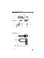
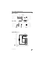
1
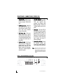
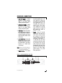
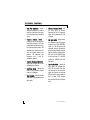
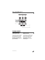
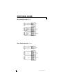
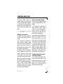
model 1200/5 2 © 2003 Directed Electronics, Inc CONGRATULATIONS Congratulations for choosing a Directed Audio power amplifier from Directed Electronics, the industry leader in high quality automotive security and audio equipment since 1990. Directed Audio power amplifiers continue to set new standards of performance, reliability, and affordability in the mobile electronics industry. Featuring high-efficiency MOSFET power supplies, flexible on-board crossovers, and state of the art audio design, Directed Audio power amplifiers will excite and delight the mobile sound enthusiast with years of high-quality audio reproduction. Directed Audio power amplifiers come with a two-year limited warranty if installed by an authorized Directed dealer. If not installed by an authorized dealer, Directed Audio power amplifiers are covered by a one-year, parts-andlabor limited warranty. Be sure to retain your original sales receipt and refer to the warranty section of this guide for full details about your coverage. TABLE OF CONTENTS Limited Two-Year Consumer Warranty . . . . . . . . . . . . . . . . . . . . . . . . .4 Features . . . . . . . . . . . . . . . . . . . . . . . . . . . . . . . . . . . . . . . . . . . .5 Warning . . . . . . . . . . . . . . . . . . . . . . . . . . . . . . . . . . . . . . . . . . . . .5 Installation Guidelines . . . . . . . . . . . . . . . . . . . . . . . . . . . . . . . . . . .6 Front Panel Connections/Status LED . . . . . . . . . . . . . . . . . . . . . . . . . .8 Rear Panel Connections . . . . . . . . . . . . . . . . . . . . . . . . . . . . . . . . . .9 Top Panel Controls . . . . . . . . . . . . . . . . . . . . . . . . . . . . . . . . . . . . . .10 Top Panel Features . . . . . . . . . . . . . . . . . . . . . . . . . . . . . . . . . . . . .11 Speaker Wiring Diagrams . . . . . . . . . . . . . . . . . . . . . . . . . . . . . . . . .12 Combined Amplifiers . . . . . . . . . . . . . . . . . . . . . . . . . . . . . . . . . . . .13 Parallel Synced Gain Connections/Settings . . . . . . . . . . . . . . . . . . . . .14 External Synced Bridged Connections/Settings . . . . . . . . . . . . . . . . . . .16 Crossover Settings and Gain Adjustment . . . . . . . . . . . . . . . . . . . . . . .18 Specifications . . . . . . . . . . . . . . . . . . . . . . . . . . . . . . . . . . . . . . . . .19 © 2003 Directed Electronics, Inc 3 LIMITED TWO-YEAR CONSUMER WARRANTY Directed Electronics, Inc. promises to the original purchaser, to replace this product should it prove to be defective in workmanship or material under normal use, for a period of two years from the date of purchase by the dealer as indicated by the date code marking of the product PROVIDED the product was installed by an authorized Directed dealer. During this two year period, there will be no charge for this replacement PROVIDED the unit is returned to Directed, shipping pre-paid. If the unit is installed by anyone other than an authorized Directed dealer, the warranty period will be one year from the date of purchase by the dealer as indicated by the date code marking of the product. During this one-year period there will be no charge for this replacement PROVIDED the unit is returned to Directed, shipping pre-paid. This warranty is non-transferable and does not apply to any unit that has been modified or used in a manner contrary to its intended purpose, and does not cover damage to the unit caused by installation or removal of the unit. This warranty is void if the product has been damaged by accident or unreasonable use, neglect, improper service or other causes not arising out of defects in materials or construction. ALL WARRANTIES INCLUDING BUT NOT LIMITED TO EXPRESS WARRANTY, IMPLIED WARRANTY, WARRANTY OF MERCHANTABILITY, FITNESS FOR PARTICULAR PURPOSE, AND 4 WARRANTY OF NON-INFRINGEMENT OF INTELLECTUAL PROPERTY ARE EXPRESSLY EXCLUDED TO THE MAXIMUM EXTENT ALLOWED BY LAW, AND DIRECTED NEITHER ASSUMES NOR AUTHORIZES ANY PERSON TO ASSUME FOR IT ANY LIABILITY IN CONNECTION WITH THE SALE OF THE PRODUCT. DIRECTED HAS ABSOLUTELY NO LIABILITY FOR ANY AND ALL ACTS OF THIRD PARTIES INCLUDING ITS AUTHORIZED DEALERS OR INSTALLERS. Unit must be returned to Directed, postage pre-paid, with: consumer’s name, telephone number, and address, authorized dealer’s name and address, and product description. IN ORDER FOR THIS WARRANTY TO BE VALID, YOUR UNIT MUST BE SHIPPED WITH PROOF OF INSTALLATION BY AN AUTHORIZED DIRECTED DEALER. ALL UNITS RECEIVED BY DIRECTED FOR WARRANTY REPAIR WITHOUT PROOF OF DIRECTED DEALER INSTALLATION WILL BE COVERED BY THE LIMITED ONE-YEAR PARTS AND LABOR WARRANTY. Note: This warranty does not cover labor costs for the removal and reinstallation of the unit. BY PURCHASING THIS PRODUCT, THE CONSUMER AGREES AND CONSENTS THAT ALL DISPUTES BETWEEN THE CONSUMER AND Directed SHALL BE RESOLVED IN ACCORDANCE WITH CALIFORNIA LAWS IN SAN DIEGO COUNTY, CALIFORNIA. © 2003 Directed Electronics, Inc FEATURES Dual high-speed MOSFET switching power supplies. Remote subwoofer level control and switchable 8 dB bass EQ function. Complimentary bipolar outputs (ch 1-4), and high-current MOSFET outputs (sub channel). Two, four, and six channel input allows full access to source or processor output functions. Five channel expandable architecture supports single or multiple amp system designs. Master/slave function allows synced bridged or parallel operation with model 750d. Thermal, DC offset, reverse polarity, and short circuit protection with status LED. Summed stereo full-range RCA output jacks. Top-mounted controls are easily accessed for system tuning. Gold-plated wire terminals and RCA connectors ensure maximum signal transfer. Dual continuously variable 12 dB/octave two-way active crossovers (ch 1-4). Rugged one-piece extruded heat sink finished with injection-molded mounting feet. Continuously variable 24 dB/ octave low-pass crossover (sub channel). Switchable 30Hz, 24 dB/octave subsonic filter and phase invert switch (sub channel). WARNING High-powered car audio systems may produce sound pressure levels that exceed the threshold at which hearing loss may result. © 2003 Directed Electronics, Inc They may also impair a driver’s ability to hear traffic sounds or emergency vehicles. Use common sense and practice safe listening habits when listening to or adjusting your audio system. 5 INSTALLATION GUIDELINES 1. Please read this owner’s manual carefully before installing this amplifier. 2. Disconnect the battery ground terminal prior to making any electrical connections. 3. Check for any hazards or obstructions such as gas tanks, fuel or brake lines, and wiring harnesses before mounting the amplifier. 4. Pick a mounting location that will provide adequate access and ventilation and protect the amplifier from heat, moisture, and dirt. 5. Avoid sharp metal areas when routing cables to the amplifier, and run RCA cables away from the power cables and other potentially noisy car harnesses. 6. The amplifier should be grounded with a short, heavy gauge wire connected directly to the car at a bare metal surface, preferably scraped body sheet metal. Do not use factory ground locations, seat bolts, or brackets that are spot welded. 7. Always fuse your power connection within eight to ten inches of the 6 battery terminal. Use a fuse or circuit breaker rated slightly more than the on-board fuse(s) of the amplifier(s). The gauge of power wire used should take into account the total current draw of the system, and the length of wire used. IASCA and other auto sound competition organizations have charts available for this; you can also find a chart in the MECP study guide. Minimum wire gauge recommendations for the individual amplifiers are listed on the specification page. Always use the same gauge wire for the amplifier ground that you use for the power wire. Be sure to examine the battery ground cable of the vehicle, and if necessary, upgrade it by adding an additional ground wire that is the same gauge as the amplifier’s power wire. Remember, the amplifier can only deliver its rated output when it is not current limited by the power and ground supply wires. 8. This amplifier is designed to drive a speaker load that measures from 28 ohms (sub ch 1-4 ohms). Keep in mind that heat is the long-term enemy of automotive electronics © 2003 Directed Electronics, Inc and the lower your speaker load, the more heat is generated. For low impedance speaker applications or restricted ventilation installations, an external cooling fan may be advisable. 9. Battery and ground connections to the vehicle should be made with crimped ring terminals of the appropriate size (surface area is what counts); soldering the terminals after crimping is also recommended. © 2003 Directed Electronics, Inc 10. Due to the high-frequency MOSFET switching power supply, filtering the power cable is not generally required (remember that the amp can’t deliver full output if the power supply is restricted). Proper grounding of the signal source is mandatory for the amplifier to reach its performance peak. If the RCA inputs are not grounded adequately via the signal source, electrical noise from the vehicle may be picked up in the system. 7 FRONT PANEL CONNECTIONS/STATUS LED 5. RCA Bridge Output Jack - This output sends an out-of-phase signal to a 750d slave amplifier when connected in the External Synced Bridged combination. (Refer to the Combined Amplifiers section of this guide.) 1. RCA Input Jacks - Accepts line level outputs from head units or signal processors between 150mV and 8 volts. 2. RCA Sub Input Jacks - Accepts line level outputs from head units or signal processors between 150mV and 8 volts for the subwoofer section of the amplifier. 6. Status LEDs - The Power LED will light GREEN to indicate the amplifier is on and operating normally. The GREEN LED will turn off and the Protection LED will light RED when the amplifier has shut itself down due to speaker short circuit, DC offset or overheating. 3. RCA Output Jacks - These pass through RCA jacks can be used to send a signal to a second amplifier. It is the summed stereo output of the one through four channel inputs of the amplifier. 7. Remote Sub Level Control - Controls the subwoofer amplifier gain controls from a remote location for ease of adjustment during listening. 4. RCA Sync Out Jack - This RCA jack sends a synced, or in-phase, gain matched signal to a 750d slave amplifier when connected in the Parallel Synced Gain combination. (Refer to the Combined Amplifiers section of this guide.) Warning: DO NOT connect a level control knob from other manufacturers to the Remote Sub Level Control of any Directed amplifier. Even though the connectors fit properly, the control knob and connector pin positions may be different and the amplifier will be damaged. FIGURE 1—AMPLIFIER CONNECTIONS 1200/5 FRONT 2 3 4 1 1+2 3+4 SUB 1-4 OUT 5 SUB OUT SLAVE R SYNC OUT L BRIDGE OUT 6 7 MASTER POWER 8 REMOTE PROTECTION © 2003 Directed Electronics, Inc REAR PANEL CONNECTIONS 1. Sub Out Terminals - Connect subwoofers to these terminals. (Refer to the Speaker Wiring Diagrams section of this guide.) turns on the amplifier when (+) 12 volt is applied to it. Connect it to the remote turn on lead of the head unit or signal source. If a (+) 12 volt remote turn on lead is not available, Remote Power Adapter (P/N #55000) can be used to supply a remote turn on signal. DO NOT connect this terminal to constant (+) 12 volt. 2. Speaker Out Terminals - Connect the speakers to these terminals. (Refer to the Speaker Wiring Diagrams section of this guide.) 3. Power Fuses - These fuses protect the amplifier against internal electrical damage and are meant to protect the amplifier only. All other power connections should be fused at the source. 4. (+) 12 Volt Power - Connect this terminal through a FUSE or CIRCUIT BREAKER to the positive terminal of the vehicle battery or the positive terminal of an isolated audio system battery. WARNING: Always protect this power wire by installing a fuse or circuit breaker of the appropriate size within 12 inches of the battery terminal connection. 5. Remote Turn On - This terminal 6. Ground - Connect this terminal directly to the sheet metal chassis of the vehicle, using the shortest wire necessary to make this connection. Always use wire of the same gauge or larger than the (+) 12 volt power wire. The chassis connection point should be scraped free of paint and dirt. Use only quality crimped and/or soldered connectors at both ends of this wire. DO NOT connect this terminal directly to the vehicle battery ground terminal or any other factory ground points. FIGURE 2—AMPLIFIER CONNECTIONS 1200/5 REAR 1 SUB OUT © 2003 Directed Electronics, Inc 2 3 REAR R FRONT R L L FUSE 40A x 3 4 5 6 BATT REM GND 9 TOP PANEL CONTROLS 1. Input Gain Adjustment - Controls amplifier sensitivity and is used to match the input level of the amplifier to the output level of the signal source. 6. Subsonic Frequency Switch - Sets the cutoff point for subsonic frequencies at 30 Hz. Frequencies below will be attenuated by 24db per octave. 2. Crossover Selection Switch Controls the type of filter for the onboard active crossovers. FLAT does not attenuate any frequencies and is for full-range speaker systems. HPF attenuates low frequencies and is used for mid-range speakers and tweeters. LPF attenuates high frequencies and is used for subwoofers speakers. 7. Sub Input Switch - Controls where the subwoofer section of the amplifier gets its signal. If the SUB INPUT switch is in the ON position the subwoofer section of the amplifier will get its signal internally summed from the channels one through four RCA jacks, and the SUB RCA jacks do not need input. If in the OFF position the SUB RCA jacks must have input. 3. Crossover Frequency Adjustment Adjusts the crossover point for the on-board active crossovers. 4. Sub Phase Switch - Changes the phase of the subwoofer speaker output by 180 degrees 5. Bass EQ Switch - Adds 8db of additional boost to the subwoofer output when active. 10 8. Input Parallel Switch - Controls the input signal to the indicated channels. If the 3+4 switch is ON, channels three and four will derive their signal from channels one and two RCA jacks and no input is needed. If the 3+4 switch is OFF, channels three and four RCA jacks must have input. © 2003 Directed Electronics, Inc FIGURE 3—AMPLIFIER CONTROLS 1200/5 TOP 4 5 6 PHASE BASS EQ SUBSONIC 0 180 OFF FREQ ON OFF FREQ ON FREQ 3 50Hz 2 500Hz 50Hz 1+2 GAIN 500Hz 30Hz 3+4 LPF HPF FLAT GAIN 250Hz SUB LPF HPF FLAT GAIN 1 MIN MAX OFF MIN ON 3+4 INPUT MAX OFF MIN MAX ON 7 SUB INPUT 8 TOP PANEL FEATURES Control Panel Cover Remove/Install The gain and filter controls are located under a control panel cover on top of the amplifier. The control panel cover must be removed to gain access to the gain and filter controls. Four Allen-head screws hold the control panel cover to the amplifier top panel, one at each corner. They can be removed with the wrench supplied in the hardware pack. © 2003 Directed Electronics, Inc 11 SPEAKER WIRING DIAGRAMS Five channel operation (top view) Three channel operation (top view) 12 © 2003 Directed Electronics, Inc COMBINED AMPLIFIERS The Directed 1200/5 channel five subwoofer section can be combined with a 750d in a master/slave combination for increased power and accurate level matching. They are the Parallel Synced Gain and External Synced Bridged combinations. NOTE: The Directed 1200/5 is always the master amplifier in these combinations. Parallel Synced Gain The Parallel Synced Gain combination includes a master amplifier and a slave amplifier. In this master/slave combination the master amplifier’s pre-amp controls remain active and the slave amplifier’s pre-amp is bypassed. This allows the master amplifier to control gain, filter, and sub-level on both amplifiers. The Parallel Synced Gain combination allows the amplifiers to drive their own separate subwoofer(s) while being synced together via an in-phase audio pre-amp signal from the master amplifier. Woofer wiring connections to the amplifier subwoofer outputs in this combination should be standard in-phase configurations, creating a parallel speaker combination. (Refer to Parallel Synced Gain section of this guide for amplifier and speaker connection diagrams.) © 2003 Directed Electronics, Inc External Synced Bridged The External Synced Bridged combination includes a master amplifier and a slave amplifier. In this master/slave combination the master amplifier’s pre-amp controls remain active and the slave amplifier’s pre-amp is bypassed. This allows the master amplifier to control gain, filter, and sub-level on both amplifiers. This combination allows the amplifiers to drive common subwoofer loads while being synced together via an out-ofphase audio pre-amp signal from the master amplifier. In this wiring configuration the master amplifier sends the positive signal to the speaker while the slave amplifier sends the negative signal, making an externally bridged speaker combination. (Refer to External Synced Bridged section of this guide for amplifier and speaker connection diagrams.) Combined Amplifiers Gain and Filter Settings Set the Subsonic, EQ, and other filter settings on the master amplifier to the positions that achieve the best sound quality. Follow the adjustment guidelines discussed in the Crossover and Gain Adjustment section of this guide. 13 PARALLEL SYNCED GAIN CONNECTIONS/SETTINGS 1. Input/Output Signal - Connect these RCA jacks as described in the Front Panel Connections/Controls section of this guide. 2. Remote Sub Level Control - Connect the Remote Sub Level control to the 1200/5 only. The 1200/5 control panel subwoofer adjustments are used first to set the overall gain for all synced amplifiers, then the Remote Sub Level control can adjust the gain of all synced amplifiers by adjusting its control knob. 3. Signal Connection - Connect an RCA cable between the SYNC OUT RCA jack of the 1200/5 and the SLAVE IN RCA jack of the slaved 750d as shown in Figure 5. 14 4. Slave/Master Switch - Set the slave/master switch of the 750d to the slave position. This will put the I/O RCA jack in the SLAVE IN mode so it will accept the audio signal from the 1200/5’s sync out RCA jack. 5. Subwoofer Speaker Connection - In this amplifier combination each amplifier must drive its own separate subwoofer(s). Connect the speaker terminals of each amplifier to any combination of one or more subwoofers that results in nominal impedance between 1 and 4 ohms. Make sure that each amplifier sees the same speaker impedance. © 2003 Directed Electronics, Inc FIGURE 5—PARALLEL SYNC GAINED 750d/1200/5 Master (1200/5) 1 1+2 Do Not Use SUB 3+4 1-4 OUT SUB OUT SLAVE R SYNC OUT L BRIDGE OUT MASTER POWER REMOTE PROTECTION 2 Slave (750d) MIN 3 INPUT I/O SUB LEVEL SLAVE R SLAVE IN SYNC OUT L BRIDGE OUT MASTER REMOTE 4 Do Not Use MAX Do Not Use Speaker Wiring (top view) MASTER 1200/5 - SUB SUBWOOFER + - + SLAVE 750D - 5 + + + NOTE: © 2003 Directed Electronics, Inc The dual + and -- sub-out terminals of the 750d are paralleled internally and the combined load impedance should be taken into consideration when connecting multiple subwoofers. 15 1. Input/Output Signal - Connect these RCA jacks as described in the Front Panel Connection/Controls section of this guide. 2. Remote Sub Level Control - Connect the Remote Sub Level control to the 1200/5 only. The 1200/5 control panel subwoofer adjustments are used first to set the overall gain for all synced amplifiers, then the Remote Sub Level control can adjust the gain of all synced amplifiers by adjusting its control knob. 3. Signal Connection - Connect an RCA cable between the BRIDGE OUT jack of the 1200/5 and the SLAVE IN jack of the slaved 750d as shown in Figure 6. 4. Slave/Master Swj1 TrT*(u)Tj0 Tr0.3607 0 TD(t)T552R61ront Panel Connection/Controls 16 © 2003 Directed Electronics, Inc FIGURE 6—EXTERNAL SYNC BRIDGED 600d/1100d5 Master (1200/5) 1 1+2 Do Not Use SUB 3+4 1-4 OUT SUB OUT SLAVE R SYNC OUT L BRIDGE OUT MASTER POWER REMOTE PROTECTION 2 Slave (750d) MIN 3 INPUT I/O SUB LEVEL SLAVE R SLAVE IN SYNC OUT L BRIDGE OUT MASTER REMOTE 4 Do Not Use MAX Do Not Use Speaker Wiring (top view) MASTER 1200/5 SUB 12 gauge 5 + SLAVE 750D + - - + 12 gauge + NOTE: © 2003 Directed Electronics, Inc The dual + and -- sub-out terminals of the 750d are paralleled internally and the combined load impedance should be taken into consideration when connecting multiple subwoofers. 17 CROSSOVER SETTINGS AND GAIN ADJUSTMENT Your Directed Audio power amplifier needs to be adjusted carefully to achieve maximum performance. These are some guidelines to follow when fine-tuning the amplifier. 18 For full-range and simultaneous stereo/mono bass applications, the crossover selection switch should be set to FLAT. If the amplifier is driving your subwoofers, set the switch to LPF, and for mid-bass/midrange output, set to HPF. The crossover frequency control needs to be adjusted to suit your particular system. For subwoofer applications, try to keep the setting low enough to prevent the image smearing (you should not be able to hear male voices from the subwoofer) but not so low as to create a gap between the subwoofer and the midbass/midrange speakers. For mid-bass/midrange settings, try to keep the setting low enough to keep your sound stage in front of you, without overdriving the speaker. It will be to your advantage to spend some extra time with this adjustment, listening to familiar music or system set-up discs to achieve the kind of musical reproduction that you prefer. The gain adjustment allows you to set proper signal match for clean, quiet amplifier operation. For full-range and simultaneous stereo/mono bass applications, start by playing some music you are familiar with. With the gain adjustment on the amplifier in the middle of its rotation, bring up the volume on your head unit to the 3/4 volume setting or until you start to hear distortion or clipping. If you hear distortion before you reach the 3/4 volume setting of your head unit, reduce the gain setting on the amplifier and start to raise the head unit volume again. When you can listen to the music at or slightly above 3/4 on your head unit without audible distortion, slowly raise the gain of the amplifier until distortion is heard, then back off the gain until the distortion is not audible. This setting will allow you to reach full output with all but the quietest of source material, while avoiding excessive noise in the system. For systems using the Remote Sub Level Adjustment, increase the subwoofer gain on the amplifier by 25% and set the Remote Sub Level knob to the center position after making all system gain and filter adjustments. This will give the Remote Sub Level Control a wider range of adjustment to the subwoofer output. The same procedure should be used for adjusting the amplifier when the on-board crossover is set to LPF or HPF, but you will also have to take into consideration the effect that gain adjustment has on system frequency response and imaging. Again, plan on spending some time with music that you know, getting the gain and crossover settings the way you like. Test discs and analyzers may help with this process, but in the end it's your ears that count - listen to the music! © 2003 Directed Electronics, Inc SPECIFICATIONS Directed model 1200/5 Ch 1-4 Sub Ch. RMS continuous power per channel, Channels 1-4 driven into 4 ohms from 20 to 20,000 Hz, with less than 0.08% total Harmonic Distortion @ 14.4 VDC. Sub channel driven into 4 ohms from 20-250 Hz, with less than 0.4% THD @ 14.4 VDC. 75 watts 275 watts RMS continuous power per channel, Channels 1-4 driven into 2 ohms from 20 to 20,000 Hz, with less than 0.1% Total Harmonic Distortion @ 14.4 VDC. Sub channel driven into 2 ohms from 20-250 Hz, with less than 0.6% THD @ 14.4 VDC. 125 watts 400 watts RMS continuous power, 3-channel operation, channels 1-4 bridged into 4 ohms from 20 to 20,000 Hz, with less than 0.1% Total Harmonic Distortion @ 14.4 VDC. Sub channel driven into 1 ohm from 20-250 Hz, with less than 0.6% THD @ 14.4 VDC. 250x2 watts 600 watts Dynamic power rating (IHF-202 Standard) at minimum load 1300 watts Signal-to-Noise Ratio Greater than 95 dB (Ch 1-4), 80dB (sub) 20-20,000 Hz ± 0.5 dB (Ch 1-4) Greater than 100 (Ch 1-4), 50 (sub) Switchable high or low pass 12 dB/octave, continuously variable 50 to 500 Hz Low pass 24 dB/octave, variable 30 to 250Hz Switchable 8 dB/octave, 20K ohms Variable from 150 mV to 8 volt 2 to 8 ohms, stereo 4 to 8 ohms, bridged 1 to 4 ohms 10 to 16 VDC 120A #4 Frequency Response Damping Factor @ 4 ohm Crossover (Ch 1-4) Subwoofer Crossover Bass Equalization Input Impedance Input Sensitivity Output Impedance (ch 1-4) (Sub ch.) Supply Voltage Fusing and Power Minimum Cable Requirements (AWG) (Per amp, trunk mounted) © 2003 Directed Electronics, Inc 19 The company behind this system is Directed Electronics, Inc. Since its inception, Directed has had one purpose, to provide customers with the finest vehicle security, car stereo products, rear seat entertainment, and accessories available. The recipient of more than 20 patents in the field of advanced electronic Directed Electronics, Inc. Vista, California 92081 www.directed.com technology, Directed is ISO 9001 registered. Directed® is committed to delivering world-class quality products and services that excite and delight our customers. Directed is a proud member of Quality Directed products are sold and serviced throughout North America and around the world Call 800 274 0200 for more information about our products and services © 2003 Directed Electronics, Inc. - All rights reserved - G45059 11/03