1
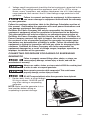
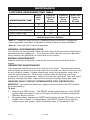
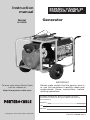
Instruction
manual
Model
ESPAÑOL: PÁGINA 29
FRANÇAIS: PAGE 57
Generator
H1000IS
To learn more about Porter-Cable
visit our website at:
http://www.porter-cable.com
IMPORTANT
Please make certain that the person who is
to use this equipment carefully reads and
understands these instructions before
starting operations.
The Model and Serial No. plate is located on the frame.
Record these numbers in the spaces below and retain for
future reference.
Model No.
Type
Serial No.
Copyright © 2003 Porter-Cable Corporation
Part No. D28469-032-0
SAFETY GUIDELINES / DEFINITIONS
This manual contains information that is important for you to know and understand. This information relates to protecting YOUR SAFETY and PREVENTING EQUIPMENT PROBLEMS. To
help you recognize this information, we use the symbols below. Please read the manual and
pay attention to these sections.
indicates an imminently hazardous situation which, if not avoided, will result in
death or serious injury.
indicates a potentially hazardous situation which, if not avoided, could result
in death or serious injury.
indicates a potentially hazardous situation which, if not avoided,may result in
minor or moderate injury
used without the safety alert symbol indicates potentially hazardous situation
which, if not avoided, may result in property damage.
CONSUMER SAFETY INFORMATION
Read Operators Manual. Do not operate equipment until you have read
operators Manual for Safety, Assembly, Operation, and Maintenance
Instructions.
This product may not be equipped with a spark arresting muffler. If the
product is not equipped and will be used around flammable materials, or
on land covered with materials such as agricultural crops, forest, brush, grass, or other similar
items, then an approved spark arrester must be installed and is legally required in the state of
California. It is a violation of California statutes section 130050 and/or sections 4442 and 4443
of the California Public Resources Code, unless the engine is equipped with a spark arrester, as
defined in section 4442, and maintained in effective working order. Spark arrester are also
required on some U.S. Forest Service land and may also be legally required under other
statutes and ordinances.
Engine exhaust contains chemicals known, in certain quantities, to cause
cancer, birth defects or other reproductive harm.
IMPORTANT SAFETY INSTRUCTIONS
Improper operation or maintenance of this product could result in serious
injury and property damage. Read and understand all warnings and
operating instructions before using.
RISK OF ELECTROCUTION AND FIRE
HAZARD
WHAT CAN HAPPEN
Attempting to
connect generator
directly to the
electrical system
of any building
structure.
Back feeding electricity through
a building’s electrical system to
the outside utility feed lines
could endanger repair persons
attempting to restore service.
D28469
2- ENG
HOW TO PREVENT IT
Never backfeed electricity
through a structure's electrical
system.
RISK OF ELECTROCUTION AND FIRE
(Continued)
HAZARD
WHAT CAN HAPPEN
HOW TO PREVENT IT
Attempting to
connect generator
directly to the
electrical system
of any building
structure.
(Continued)
Attempting to connect to the incoming utility service could result
in electrocution.
Restoration of electrical service
while the generator is connected
to the incoming utility could
result in a fire or serious damage
if an isolator switch is not
installed.
Failure to use a double throw
transfer switch when connecting
to a structure's electrical system
can damage appliances and
WILL VOID the manufacturer's
warranty.
To connect to a structure's electrical system in a safe manner,
always have a Double-Throw
Transfer Switch installed by a
qualified electrician and in compliance with local ordinances.
(When installing a DoubleThrow Transfer Switch, a minimum of 10 gauge wiring must
be used.)
Operation of
generator in rain,
wet, icy, or
flooded
conditions.
Water is an excellent conductor
of electricity! Water which comes
in contact with electrically
charged components can
transmit electricity to the frame
and other surfaces, resulting in
electrical shock to anyone contacting them.
Operate generator in a clean, dry,
well ventilated area. Make sure
hands are dry before touching
unit.
Use of worn,
damaged, undersized or ungrounded extension cords.
Contact with worn or damaged
extension cords could result in
electrocution.
Inspect extension cords before
use and replace with new cord if
required.
Use of undersize extension
cords could result in overheating
of the wires or attached items,
resulting in fire.
Use proper size (wire gauge)
cordset for application see chart
in the Assembly section of this
manual.
Use of ungrounded cordsets
could prevent operation of
circuit breakers and result in
electrical shock.
Always use a cordset having a
grounding wire with an
appropriate grounding plug. DO
NOT use an ungrounded plug.
Placing generator
on or against
highly conductive
surface, such as a
steel walkway or
metal roof.
Accidental leakage of electrical
current could charge conductive
surfaces in contact with the
generator.
Place generator on low conductivity surface such as a concrete
slab.
Improper
connection of
items to
generator.
Exceeding the load capacity of
the generator by attaching too
many items, or items with very
high load ratings to it could
result in overheating of some
items or their attachment wiring
resulting in fire or electrical
shock.
ALWAYS operate generator a
minimum of six feet from any
conductive surface.
3- ENG
Read the load rating chart and
instructions in the Wattage Calculation section. Make sure that
the summation of electrical
loads for all attachments does
not exceed the load rating of the
generator.
D28469
RISK OF ELECTROCUTION AND FIRE
(Continued)
HAZARD
Operation of unit
when damaged,
or with guards or
panels removed.
WHAT CAN HAPPEN
HOW TO PREVENT IT
Attempting to use the unit
when it has been damaged, or
when it is not functioning
normally could result in fire or
electrocution.
Do not operate generator with
mechanical or electrical
problem. Have unit repaired by
an Authorized Service Center.
Removal of guarding could
expose electrically charged
components and result in
electrocution.
Do not operate generator with
protective guarding removed.
RISK OF FIRE
HAZARD
WHAT CAN HAPPEN
HOW TO PREVENT IT
Attempting to
fill the fuel tank
while the engine
is running.
Gasoline and gasoline vapors
can become ignited by coming
in contact with hot components
such as the muffler, engine
exhaust gases, or from an
electrical spark.
Turn engine off and allow it to
cool before adding fuel to the
tank. Equip area of operation
with a fire extinguisher certified
to handle gasoline or fuel fires.
Sparks, fire, hot
objects
Cigarettes, sparks, fires, or
other hot objects can cause
gasoline or gasoline vapors to
ignite.
Add fuel to tank in well
ventilated area. Make sure there
are no sources of ignition near
the generator.
Improper storage
of fuel
Improperly stored fuel could
lead to accidental ignition. Fuel
improperly secured could get
into the hands of children or
other unqualified persons.
Store fuel in a OSHA approved
container designed to hold
gasoline. Store container in secure location to prevent use by
others.
Inadequate
ventilation for
generator
Materials placed against or near
the generator or operating the
generator in areas where the
temperature exceeds 104° F. ambient (such as storage rooms or
garages) can interfere with its
proper ventilation features causing overheating and possible ignition of the materials or buildings.
Operate generator in a clean, dry,
well ventilated area a minimum of
four feet from any building, object
or wall. DO NOT OPERATE
UNIT INDOORS OR IN ANY
CONFINED AREA.
Tampering with
factory set
engine speed
settings.
Engine speed has been factory
set to provide safe operation.
Tampering with the engine speed
adjustment could result in
overheating of attachments and
could cause a fire.
D28469
4- ENG
Never attempt to “speed-up”
the engine to obtain more performance. Both the output
voltage and frequency will be
thrown out of standard by this
practice, endangering
attachments and the user.
RISK OF FIRE
(Continued)
HAZARD
WHAT CAN HAPPEN
HOW TO PREVENT IT
Overfilling the fuel
tank – fuel
spillage.
Spilled fuel and its vapors can
become ignited from hot
surfaces or sparks.
Use care in filling the tank to
avoid spilling fuel. Make sure
fuel cap is secured tightly and
check engine for fuel leaks
before starting engine. Move
generator away from refueling
area or any spillage before
starting engine. Allow for fuel
expansion. Keep maximum fuel
level ¼ inch below the tip of the
fuel tank. Never refuel with the
engine running.
RISK OF INJURY AND PROPERTY
DAMAGE WHEN TRANSPORTING
GENERATOR
HAZARD
Fire, Inhalation,
Damage to
Vehicle Surfaces
WHAT CAN HAPPEN
Fuel or oil can leak or spill and
could result in fire or breathing
hazard, serious injury or death
can result. Fuel or oil leaks will
damage carpet, paint or other
surfaces in vehicles or trailers.
HOW TO PREVENT IT
If generator is equipped with a
fuel shut-off valve, turn the valve
to the off position before
transporting to avoid fuel leaks.
If generator is not equipped with
a fuel shut-off valve, drain the
fuel from tank before transporting. Transport fuel only in an
OSHA approved container.
Always place generator on a
protective mat when transporting to protect against damage to
vehicle from leaks. Remove
generator from vehicle immediately upon arrival at your destination.
RISK OF BREATHING - INHALATION
HAZARD
HAZARD
Gasoline
engines produce
toxic carbon
monoxide
exhaust fumes.
WHAT CAN HAPPEN
Breathing exhaust fumes will
cause serious injury or death.
5- ENG
HOW TO PREVENT IT
Operate generator in clean, dry,
well ventilated area. Never
operate unit in enclosed areas
such as garages, basements,
storage, sheds, or in any
location occupied by humans or
animals. Keep children, pets and
others away from area of operating unit.
D28469
RISK OF UNSAFE OPERATION
HAZARD
WHAT CAN HAPPEN
HOW TO PREVENT IT
Operation of
generator in
careless manner
All sources of energy include the • Review and understand all of
potential for injury. Unsafe
the operating instructions and
operation or maintenance of your
warnings in this manual.
generator could lead to serious
• Become familiar with the operinjury or death to you or others.
ation and controls of the
generator. Know how to shut it
off quickly.
• Equip area of operation with a
fire extinguisher certified to
handle gasoline or fuel fires.
• Keep children or others away
from the generator at all times.
Operation of
voltage
sensitive appliances without a
voltage surge
protector
Any gasoline operated
household generator will incur
voltage variations causing
damage to voltage sensitive appliances or could result in fire.
Always use a U.L. listed voltage
sensitive surge protector to
connect voltage sensitive
appliances (TV, computer, stereo, etc.). Failure to use a U.L.
listed voltage surge protector
will void the warranty on your
generator.
Notice: A multiple outlet strip is
not a surge protector. Make sure
you use a U.L. listed voltage
surge protector
Raising or
suspending
generators
equipped with
lift rings
improperly
Operating
generator while
suspended
D28469
Generator could fall causing
serious injury or death to you or
others.
Always use proper connecting
procedures as described in this
manual when connecting cables,
chains, or straps for raising or
suspending generators equipped
with lift rings.
Improper raising or suspending
can cause damage to the
generator.
Always use cables, chains, or
straps rated at 2000 lbs working
load or more to raise or suspend
generator.
Generator will not operate
properly and will cause damage
to the generator and could
cause serious injury or death to
you or others.
Never operate generator while
suspended or in an unlevel
position. Always operate
generate on a flat, level surface.
6- ENG
RISK OF HOT SURFACES
HAZARD
Contact with hot
engine and
generator
components.
WHAT CAN HAPPEN
HOW TO PREVENT IT
Contact with hot surfaces, such
as engines exhaust components,
could result in serious burns.
During operation, touch only the
control surfaces of the
generator. Keep children away
from the generator at all times.
They may not be able to recognize the hazards of this
product.
RISK OF MOVING PARTS
HAZARD
Contact with
moving parts
can result in
serious injury.
WHAT CAN HAPPEN
The generator contains parts
which rotate at high speed during
operation. These parts are
covered by guarding to prevent
injury.
HOW TO PREVENT IT
Never operate generator with
guarding or cover plates
removed. Avoid wearing loose
fitting clothing or jewelry which
could be caught by moving parts.
RISK FROM LIFTING
HAZARD
Lifting a very
heavy object.
WHAT CAN HAPPEN
Serious injury can result from attempting to lift too heavy an
object.
7- ENG
HOW TO PREVENT IT
The generator is too heavy to be
lifted by one person. Obtain assistance from others before you
try to move it.
D28469
CONSUMER GENERAL AND SERVICE INFORMATION
• Please read and follow these instructions for proper use and maintenance.
• If you experience any problems and need assistance, please call us at our toll
free number 1-888-559-8550, Monday through Saturday.
• If repair or service part purchase is required, our many Authorized Warranty
Service Centers are conveniently located and equipped to handle all inwarranty and out-of-warranty service.
• For the location of the nearest Authorized Warranty Service Center call
1-888-559-8550, 24 hours a day, 7 days a week.
• Retain sales receipt as proof of purchase for warranty service.
• Read and understand all safety warnings.
• Do not operate this unit until you have read and understand this Owners
Manual for Safety, Operation, and Maintenance Instructions.
• Do not operate this unit until you have read and understand the Engine
Owners Manual for Safety, Operation, and Maintenance Instructions.
Note: Photographs and line drawings used in this manual are for reference only and
do not represent a specific model.
SPECIFICATIONS
MODEL
HORSE POWER
RATED/SURGE WATTS
VOLTAGE
AMPERAGE
PHASE
HERTZ
ENGINE SPEED
MAX. AMBIENT TEMP.
FUEL CAPACITY
RUN TIME @ 50%/100%
D28469
H1000IS
20
10000/19500
120/240V
83.3 A41.7 A
SINGLE
60 Hz
3600 RPM
104° F
7 GALLON
9.9/4.9 HOURS
8- ENG
ASSEMBLY
Read this manual. Do not attempt to operate equipment
until you have read this Manual for Safety, Operation, and
Maintenance Instructions.
NOTE: This manual is a general manual. Information in this manual may or
may not pertain to your model. Please read carefully.
NOTE: Left and right describes the location of a part with the operator
facing the outlet panel.
UNPACKING
1.
Locate the parts carton and set aside
for later use.
2.
Cut wire ties holding generator to
pallet and remove protective
wrapping.
3.
Protective
Wrapping
Wire Tie
Remove all packaging, leaving
generator on pallet.
IMPORTANT: DO NOT remove generator from
pallet.
4.
Discard all packaging.
ASSEMBLE WHEEL KIT
Tools needed:
2 - 2x4 at least 30” long
1 - 1/2” socket
1 - 1/2” open end wrench
1 - hammer
1 - pliers
Parts bag contains:
2 - Handle Grips
2 - Handle End Caps
4 - Screws, .313-18X1.75
1 - Cotter Pin
2 - Washers, 5/8" X 1.32 X .09
1 - Flat Steel Washer
2 - Axle Spacer
2 - Cap Screw 5/16-18 X 3/4
6 - Flange Nuts
2 - Wheel Brackets
1 - 5/8” Axle Cap
9- ENG
D28469
1.
Lift the gas tank end of generator
and slide 2x4 between generator
and pallet as shown.
The generator is too
heavy to be lifted by
one person. Obtain assistance from
others before lifting.
Gas Tank
2x4
2.
Place handle grips on handle assemblies.
Handle Grip
3.
Place one 5/8” washer into the bottom of
each end cap. Push end caps onto the
end of the handle assemblies.
End Cap
Handle
Assembly
5/8” Washer
4.
Attach handle assemblies to frame
using four screws and flange nuts.
NOTE: Screw on outside of frame.
NOTE: Do not tighten until all screws
and flange nuts are assembled.
D28469
10- ENG
Screws and
Flange Nuts
5.
Lift generator and remove 2x4.
6.
Lift other end of generator and
place two 2x4s between generator
and pallet as shown.
7.
2x4
On the muffler side of the engine, remove cap screws Cap
and flange nuts holding the heat shield to the frame. Screw
Reassemble cap screws, heat shield, wheel bracket,
and flange nuts and as shown. Tighten securely.
Muffler
Heat
Shield
Wheel
Bracket
Flange Nuts
8.
On other side, assemble wheel
bracket using cap screws and flange
nuts supplied. Tighten securely.
NOTE: Brackets are placed under frame
with hole facing outward.
Cap screws
Wheel Bracket
9.
Using a hammer tap axle cap onto end of axle,
without the hole.
Hole in Axle
10. Slide wheel onto axle with valve stem to the
outside.
11. Slide spacer onto axle against wheel.
12. Slide axle through axle brackets. NOTE: The pallet
will need to be removed before the wheel can be assembled.
13. Lift generator and slide pallet and 2x4s out. NOTE: Generator will tilt.
14. Lift generator and slide spacer, then wheel (with valve stem to the outside)
onto axle.
15. Slide flat steel washer onto axle against wheel.
16. Secure with cotter pin.
11- ENG
D28469
ASSEMBLE SKYHOOK
Tools needed:
1 - 1/2” socket or open end wrench
1 - 3/8" socket
1 - Torque wrench
Parts bag contains:
1 - Skyhook
2 - Upper brackets
4 - Bolts, 5/16-18 x 7/8”
4 - Lockwashers, 5/16”
4 - Nuts, Whizlock 5/16”
1.
Close fuel shut-off valve on tank
by turning clockwise until it
stops.
2.
Remove four screws, and
washers securing fuel tank to
frame. Save screws and washers
for reassembly.
3.
Carefully place fuel tank inside
frame rails as shown.
4.
Place skyhook under frame as
shown.
D28469
12- ENG
5.
Place skyhook on the fuel tank
side of the frame and install
upper bracket as shown.
6.
Wrap upper bracket around
frame.
Slide lockwashers onto bolts,
insert through brackets, and
secure with whizlock nuts.
NOTE: DO NOT tighten bolts at
this time.
Repeat steps 5-7 on other side.
7.
8.
9
Position skyhook between
arrows on label. NOTE: Bracket
should not overlap onto weld (a).
Failure to properly
position skyhook
can cause property damage,
serious injury or death, and void
the manufacturer’s warranty.
a
10. Torque four bolts to 11-12 ft.-lbs.
(132-144 in.-lbs.)
IMPORTANT: DO NOT substitute
hardware when assembling the
skyhook.
11. Place tank on frame rails and
align holes in tank with holes in
frame.
12. Install fuel tank screws and
washers. Torque screws to 2025 inch pounds (hand tight).
13. Open the fuel shut-off valve. Turn
counter clockwise until the valve
stops.
13- ENG
D28469
BATTERY INSTALLATION
The generator is equipped with a maintenance free battery.
1. For packaging purposes the black
Wire Tie
negative battery cable and battery
were secured with wire ties. Cut
Negative Battery Cable
these wire ties.
2. Connect black negative cable to
negative (-) battery post. Tighten
securely. NOTE: Make sure rubber
boot is covering positive (+) battery
terminal.
NOTE: If battery needs to be charged,
follow these instructions.
Wire Tie
When charging the
battery, do not smoke.
Keep away from any sparks. The
fumes from the battery acid can cause
an explosion. To prevent explosive
fumes from accumulating do not
charge in an enclosed area.
Sulfuric acid is a
flammable and
explosive chemical that is harmful to
the skin, eyes, and clothing.
Negative Battery Cable
Positive
Battery Cable
with rubber
boot
To prevent sparks,
disconnect the black
battery cable from the negative (-)
terminal before disconnecting the red positive cable.
1.
2.
3.
Remove black negative battery cable from the battery.
Remove red positive battery cable from the battery.
Use a portable 12 volt battery charger, if needed, to bring battery to full
charge (12.6 at 70ºF.). Refer to the battery charger’s operator’s manual for
the correct procedure. If a battery charger is not available, have an
authorized service center charge the battery.
4. Connect the battery cables.
To Prevent sparks connect the red (positive) cable to the
positive (+) terminal before connecting the black negative
cable.
When transporting unit over extremely rough terrain by
vehicle the battery should be secured.
GROUNDING THE GENERATOR
A grounding lug is supplied with the generator for use
when required by local electrical ordinances. Refer to
article 250 of the National Electrical Code to clarify any
needed grounding information. Your local electric company
or a certified electrician should be able to help you with
this information.
D28469
14- ENG
Grounding Lug
OBTAINING ELECTRICITY FROM THE GENERATOR
There are basically 2 ways to obtain electricity from a generator:
1. Use of extension cords directly from the generator to the appliance, lights,
tools, etc.
2. Use of a double-throw transfer switch installed directly to the main electrical
supply outside of house.
EXTENSION CORDS
When using an appliance or tool at a
considerable distance from the generator,
a 3-wire extension cord that has a 3blade grounding plug and a 3-slot receptacle that accepts the tool's plug MUST
be used in order to reduce the risk of
electrical shock. A cord of adequate size
must be used. Using the following chart
to determine the minimum wire size required.
Extension Cord Wire Gauge Chart
Wire
Cord
Amperage
Gauge
Length
Size
0 to 100 ft. 12 ga.
1
Up to 20 amp draw
0 to 100 ft. 10 ga.
2
Up to 30 amp draw
0 to 100 ft.
1.
An extension cord that
2.
is hot to the touch is
overloaded. Repair or replace
damaged extension cords immediately.
8 ga.
Up to 40 amp draw
When amperage exceeds 20 amp; a
12 gauge extension cord should not
be used for long distances.
When amperage exceeds 30 amp; a
10 gauge extension cord should not
be used for long distances.
DOUBLE THROW TRANSFER SWITCH
Potential hazards exist when a portable electric generator is
connected to the main electrical supply coming into the house.
It is at that point that the electrical generator could feed back into the utility
company's system causing possible electrocution of workers who are repairing
the electrical lines.
To avoid back feeding of electricity into utility systems, a double-throw transfer
switch must be installed between the generator and utility power. The DoubleThrow Transfer Switch should be installed by a licensed electrician and in compliance with all state and local electrical codes. (When installing a DoubleThrow Transfer Switch, a minimum of 10 gauge wiring must be used.)
The electrician should also install a sub-panel to isolate the circuits you would
want to use during an emergency or electrical power outage. Your generator will
not be large enough to handle the load of all the lights, appliances, TV, etc. at
one time. To select which items to run during the electrical power outage, see
Wattage Calculation section in this manual.
15- ENG
D28469
OTHER LOOSE PARTS
1.
Oil is supplied, see engine operator’s manual for correct procedure to add oil
and fuel to engine.
2. The locking plugs maybe used when needed or required.
The locking plugs are to be installed and/or used in
accordance with appropriate local electrical code
regulations. Refer to instructions enclosed with each plug for proper
installation.
3.
12V DC cables to be used with the 12V DC outlets. See Operation section.
IMPORTANT: Before any attempt to start your generator be sure to check
engine oil (See Engine Operator's manual)
OPERATION
KNOW YOUR GENERATOR
Read this General Manual and Safety Rules before operation of your Generator.
Compare the illustration in your parts manual with your generator to familiarize yourself with
the location of various controls and adjustments. Save all manuals for future references.
GENERATOR CAPACITY
IMPORTANT: Exceeding the rated capacity of your generator can result in serious damage
to your generator and connected electrical devices. See the Wattage Calculation section in
this manual to assist you in determining the appliances and tools that can be run with the
wattage capacity of your generator.
CIRCUIT BREAKERS
Each receptacle has a circuit breaker to protect the generator from overloading. If the circuit
breaker trips, unplug all electrical loads from the generator. Let the circuit breaker cool
down. Push circuit breaker button to reset.
LOW OIL SHUTDOWN
Your generator engine is equipped with Low Oil Shutdown. Low Oil Shutdown is
a safety device designed to protect your engine from damage in the event the oil
level in the crankcase is low.
If while the engine is running, the oil gets low, it will automatically shut itself
down and will not restart until the oil is added. If the oil is low before start-up,
the generator will not start until oil is added.
NOTE: The Low Oil Shutdown mechanism is very sensitive. You must fill the
engine to the full mark on the dipstick to inactivate this safety device.
OFF/RUN/START SWITCH
Placed in the start position to start engine and the off position to stop engine.
NOTE: When engine is running switch will remain in the run position.
D28469
16- ENG
IDLE CONTROL
Choose the correct application.
1.
For normal application such as power tools, small electric appliances, light
bulbs, and radios:
Place the idle control switch in the ON position. The generator
will idle down when there is no load. This lowers the engine
noise, saves on fuel consumption, and engine life.
2.
Idling down IS NOT recommend on large motors (refrigerators, freezers, etc)
or voltage sensitive electronic equipment (computers, televisions, etc). For
these applications:
Place the idle control switch in the OFF position.
12V DC OUTLET
IMPORTANT: Allow generator to run at no load for 5 minutes upon each initial
start-up to allow engine to stabilize.
IMPORTANT: When the unit is running the battery will charge. DO NOT
connect the 12V DC cables to the generator’s battery.
To charge battery:
1. Using the 12V DC cables supplied, connect the red
positive (+) 12V DC cable to the battery's positive (+)
terminal.
2. Attach the other end of the red positive (+) 12V DC cable
to the generators positive (+) 12V DC outlet.
3. Connect the black negative (-) 12V DC cable to the battery's negative (-)
terminal.
4. Attach the other end of the black negative (-) 12V DC cable to the
generators negative (-) 12V DC outlet.
5. Charge the battery according to battery or equipment manufacturer
recommendations.
BEFORE START UP
This generator has been shipped from the factory without oil in the
crankcase. Operating the unit without oil can damage the engine.
Always check engine oil level before every start. Running engine
low of oil or out of oil could result in serious damage to the engine.
Follow the steps listed below before starting generator:
1.
Check engine oil. Refer to the Engine Operator's Manual for correct grade and quantity
of oil.
2.
Check fuel level, fill as required. Make sure generator is turned off and has been allowed
time to cool down. Use clean, fresh, regular unleaded gasoline with a minimum of 87
octane. Do not mix oil with gasoline.
Never fill fuel tank completely. Fill tank to 1/2" below the bottom of
the filler neck to provide space for fuel expansion. Wipe any fuel
spillage from engine and equipment before starting engine.
17- ENG
D28469
Never fill fuel tank indoors. Never fill fuel tank when engine is
running or hot. Do not smoke when filling fuel tank.
Never run engine indoors or in enclosed, poor ventilated areas,
engine exhaust contains carbon monoxide, an odorless and
deadly gas.
3. Make sure generator is grounded in accordance with local requirements.
4. All electrical loads MUST be disconnected.
5. Idle control switch must be in the OFF position.
6. Make sure skyhook bolts are tightened and torqued to 11-12 ft.-lbs. (132-144 in.-lbs.).
Engine speed has been factory set to provide safe operation.
Tampering with the engine speed adjustment could result in overheating of attachments and could cause a fire. Never attempt to “speed-up” the engine to obtain more performance. Both the output voltage and frequency will be
thrown out of standard by this practice, endangering attachments and the user.
You MUST unplug any load from the generator before starting to
prevent permanent damage to any appliances.
TO START THE ENGINE
Never run engine indoors or in enclosed, poor ventilated
areas, engine exhaust contains carbon monoxide, an
odorless and deadly gas.
1. Open the fuel shut-off valve.
2. Move the choke control located on the engine to "CHOKE"
position. A cold engine may require to be choked longer
than a warm engine.
3. Push ON\OFF\START switch on control panel to the
"START" position to start engine. Hold in "START" position
no longer than 15 seconds per minute when trying to start
engine. Extended cranking can damage the starter motor.
4. When engine starts, gradually move the choke to the "NO Choke" position.
IMPORTANT: Allow generator to run at no load for 5 minutes upon each initial
start-up to allow engine and generator to stabilize.
STOPPING ENGINE
1.
2.
3.
Disconnect all electrical loads.
Place the ON\OFF\START switch to "OFF" position.
Close fuel shut-off valve.
CONNECTING ELECTRICAL LOADS
1.
Let engine run and warm up for five minutes after starting with no electrical
load.
Connect loads in the following manner to prevent damage to equipment:
2. Connect inductive load equipment first, inductive loads consist of
refrigerators, freezers, water pumps, air conditioners, or small hand tools.
Connect the items that require the most wattage first. See Wattage Calculation Section in this manual.
3. Connect the lights next.
D28469
18- ENG
4.
Voltage sensitive equipment should be the last equipment connected to the
generator. Plug voltage sensitive appliances such at TV's, VCR's, microwaves, ovens, computers, and cordless telephones into a UL listed voltage
surge protector, then connect the UL listed voltage surge protector to the
generator.
Failure to connect and operate equipment in this sequence
can cause damage to equipment and will void the warranty
on your generator.
Follow the wattage calculation table in the Wattage Calculation section of
this manual. Overloading the generator will cause power fluctuations and
can damage equipment and appliances.
DeVilbiss Air Power Company will only be responsible for damage to
customer's equipment when the generator is determined to be defective.
This determination will only be made by an authorized representative of
DeVilbiss Air Power Company and this decision will be final. DeVilbiss Air
Power Company reserves the right to inspect the electrical connections at
the customer's site of operation and test the generator for proper operation before any determination of liability is made. Failure to maintain the
equipment or wiring for inspection will void any claim for damages by the
customer. DeVilbiss Air Power Company will not be responsible for
equipment damaged as a result of voltage surges, improper operation or
improper installation of the generator.
CONNECTING PROCEDURE FOR RAISING OR SUSPENDING
GENERATOR
Failure to properly connect lifting cables, chains, or straps can
cause properly damage, serious injury or death, and void the
manufacturer’s warranty.
Always use cables, chains, or straps rated at 2000 lbs. working load
or more to raise or suspend generator.
Never operate generator while suspended. This could cause
property damage, serious injury or death.
DO NOT suspend objects other than generator from skyhook.
Route cable, chain, or strap through
lift ring as shown. ALWAYS use lift
ring when raising or suspending
generator.
NOTE: Make sure the generator is in a
level position before raising or
suspending to prevent damage.
1.
19- ENG
D28469
MAINTENANCE
CUSTOMER RESPONSIBILITIES TABLE
MAINTENANCE TASK
Check oil level
Before
each
use
Every 25
Hours of
Every
Season
X
See Note 2
Clean Air Filter Assembly
Prepare Unit for Storage
Every 100
Hours of
Every
Season
See Note 1
Change oil
Check Spark Plug
Every 50
Hours of
Every
Season
X
X
X
Prepare unit for storage if it is to remain
idle for more than 30 days.
Note 1: Change oil after first two (2) operating hours and every 50 operating
hours thereafter, more often if operated in extreme dusty or dirty conditions.
Note 2: Check oil after 5 hours of operation.
GENERAL RECOMMENDATIONS
The warranty of the generator does not cover items that have been subjected to
operator abuse or negligence. To receive full value from the warranty, operator
must maintain the generator as instructed in this manual.
ENGINE MAINTENANCE
Refer to the Engine Operator's manual for service and maintenance of the
engine.
GENERATOR MAINTENANCE
Your generator should be kept clean and dry at all times. The generator should
not be stored or operated in environments that includes excessive moisture, dust
or any corrosive vapors. If these substances are on the generator, clean with a
cloth or soft bristle brush. Do not use a garden hose or anything with water
pressure to clean the generator. Water may enter the cooling air slots and could
possibly damage the rotor, stator and the internal windings of the gen head.
GROUND FAULT CIRCUIT INTERRUPTER GFCI RECEPTACLE
MONTHLY: For maximum protection against electrical shock the GFCI should
be tested monthly.
To test:
1. Depress the TEST button. The RESET button should extend. If the RESET
button does not extend, notify a DeVilbiss Air Power Company Authorized
Warranty Service Center.
2. To restore power, depress the RESET button firmly into the GFCI unit until an
audible click is heard. If reset properly, the RESET button is flush with the
surface of the test button. When the button stays in, the power is ON.
D28469
20- ENG
STORAGE
If you are going to store your generator for more than 30 days, use the
following information as a guide to prepare the generator for storage.
Never store generator with fuel in the tank indoors or in
enclosed, poorly ventilated areas, where fumes can reach
an open flame, spark or pilot light as on a furnace, water heater, clothes
dryer or other gas appliances.
ENGINE PREPARATION
1.
Add fuel stabilizer to fuel tank to minimize the formation of fuel gum
deposits during storage.
2. Run engine at least 10 minutes after adding stabilizer to allow it to enter the
fuel system.
3. Next shut off engine.
4. Disconnect the spark plug wire and remove the spark plug.
5. Add one teaspoon of oil through the spark plug hole.
6. Place rag over spark plug hole and pull the recoil a few times to lubricate
the combustion chamber.
7. Replace the spark plug, but do not connect the spark plug wire.
NOTE: If a fuel stabilizer is not used, all gasoline must be drained from the tank
and carburetor to prevent gum deposits from forming on these parts and causing
possible malfunction of the engine.
GENERATOR
1.
2.
Clean the generator as outlined in the Maintenance Section on this manual.
Check that cooling air slots and openings on generator are open and
unobstructed.
BATTERY
1. Store battery as described by the battery manufacturer.
NOTE: After storing battery for a long period of time it may lose its charge. If
the battery loses its charge, manually start the engine with the battery connected. The engine will recharge the battery as it runs.
21- ENG
D28469
WATTAGE CALCULATIONS
IMPORTANT
Never exceed the rated capacity of your generator. Serious damage to the
generator or appliance could result from an overload.
1. Starting and running wattage requirements should always be calculated
when matching a generators wattage capacity to the appliance or tool.
2. There are two types of electrical appliances that can be powered by
your generator:
A. Items such as radios, light bulbs, television sets, and microwaves
have a "resistive load". Starting wattage and running wattage are
the same.
B. Items such as refrigerators, air compressors, washer, dryer, and
hand tools that use an electrical motor have an "inductive load".
Inductive load appliances and tools require approximately 2 to 4
times the listed wattage for starting the equipment. This initial load
only lasts for a few seconds on start-up but is very important when
figuring your total wattage to be used.
C. Always start your largest electric motor first, and then plug in other
items, one at a time.
NOTE: On 120-volt loads the maximum starting wattage should NOT
exceed one half of the rated generator wattage. Example: a 5000 rated
wattage generator = 2500 maximum starting wattage.
DETERMINING WATTAGE REQUIREMENTS
Before operating this generator list all of the appliances and/or tools that are
going to operate at the same time. (Then determine the starting wattage
requirements and the running wattage requirements by following example
and/or refer to household wattage calculator.)
1. First total the running wattage of all appliances and/or tools that will be
operated at the same time.
Running Watts
Starting Watts
Example 1:
Lights
=
100 Watts
0
Television
=
300 Watts
0
Slow Cooker
=
250 Watts
0
TOTAL
=650 Watts
0
2. Next the starting wattages of any appliances and/or tools that will start and
stop during operation.
Running Watts
Starting Watts
Example 2:
Small Refrigerator
500 Watts
2000 Watts
TOTAL =500 Watts
2000 Watts
D28469
22- ENG
3.
The running wattage of examples 1 & 2 totals 1150 watts. The starting
wattage of the small refrigerator is 2000 watts which is 1500 watts more
than the running watts. Take this difference of 1500 starting watts from the
refrigerator and add to the total running watts of 1150.
Example 3:
1500 Starting Watts
1150 Running Watts
TOTAL =2650 Total Watts
Generator must have a maximum capacity of at least 2650 watts.
STARTING WATTAGE REQUIREMENTS
1.
2.
3.
Some appliances and tools will list on the motor nameplate the starting
and running voltage and amperage requirements. Use the following
formula to convert voltage and amperage to wattage:
Volts X Amp = Watts
Example: 120 volts x 10 amps = 1200 watts
To determine the approximate starting wattage requirement for most
appliances and tools with inductive type motors, multiply the wattage that
was calculated by 2 to 4 times to assure adequate generator capacity. If
the nameplate information is not available use the values on the following
chart as a guide.
Remember that the starting and running wattage for resistive loads are the
same. (Example: a 100 watt light bulb requires only 100 watts to start.)
Most resistive loads will be listed in wattage.
Application Guide
3/8” Hand Drill
Jigsaw
(1/3 HP) Airless Sprayer
6” Bench Grinder
Belt Sander
Demolition Hammer
7-1/4” Circular Saw
(Small) Air Compressor
Light Bulb
Home Security
Television
Microwave
Toaster Oven
(5,000 BTU) Portable Heater
Furnace Fan
Refrigerator/Freezer
Sump Pump
Clothes Washer
Water Heater
(30,000 BTU) Air Conditioner
(12V DC) Battery Charger
Radio
Slow Cooker
Electric Blanket
Electric Skillet
Coffee Maker
Small Refrigerator
The wattage ratings
shown are averages actual wattage may vary.
To select the right generator for
your needs, total the wattage of the
items to be run at the same time.
10
0
25
0
50
0
WATTAGE
40
3
5
6
9
8
7
1
10
2
00 000 00
00 000 000 000 000 000 000
0
0
Run
23- ENG
Start
D28469
HOUSEHOLD WATTAGE CALCULATOR
DEVICES WITH HIGH STARTING (INDUCTIVE)LOADS
RUN WATTS
TIMES (X) START FACTOR
APPLIANCE OR
LOAD DEVICE*
TOTAL
800
x
3
REFRIGERATOR/
FREEZER
=
2400
=
600
x
3
SMALL REFRIGERATOR
=
1800
=
2400
x
3
AIR COND.(ROOM)
=
7200
=
1000
x
2
SUMP PUMP 1/2 HP
=
2000
=
800
x
3
FURNACE FAN 1/3 HP
=
2400
=
1000
x
2
WELL PUMP 1/2 HP
=
2000
=
=
1500
=
TELEVISION
=
300
=
MICROWAVE
=
800
=
SPACE HEATER
=
1500
=
WATER HEATER
=
4000
=
CAUTION !!
HOT PLATE
DO NOT CONNECT VOLTAGE SENSITIVE
ELECTRONIC EQUIPMENT (TV SET, COMPUTER,
ETC.) DIRECTLY TO YOUR GENERATOR. IF YOU USE
THE GENERATOR TO POWER SENSITIVE EQUIPMENT
YOU MUST USE A U.L. LISTED VOLTAGE SURGE
PROTECTOR.
NOTICE: FAILURE TO USE A U.L. LISTED VOLTAGE
SURGE PROTECTOR WILL DAMAGE YOUR
EQUIPMENT AND VOID YOUR WARRANTY.
THE IDLE CONTROL MUST BE IN THE
OFF POSITION WHEN OPERATING
LARGE MOTOR LOADS (FREEZERS,
REFRIGERATORS,ETC.) OR VOLTAGE
SENSITIVE ELECTRONIC EQUIPMENT
(TV, COMPUTERS, ETC.)
*FOR PRODUCTS NOT
LISTED REFER TO
CALCULATION
INSTRUCTIONS
**AVERAGE VALUES ACTUAL INDIVIDUAL
DEVICE VOLTAGES MAY
BE HIGHER OR LOWER
D28469
TYPICAL DEVICE
WATTAGE**
LIGHTING
CAUTION !!
TIMES NUMBER
OF BULBS
WATTS
=
60 WATT BULBS
60
x
75 WATT BULBS
75
x
=
100 WATT BULBS
100
x
=
300 WATT BULBS
300
x
=
ELECTRIC LOAD GRAND TOTAL
THIS TOTAL MUST BE LESS THAN YOUR GENERATOR RATING
WATTAGE RATING OF YOUR GENERATOR
THIS TOTAL MUST BE GREATER THAN YOUR HOUSEHOLD WATTAGE LOAD
24- ENG
TROUBLESHOOTING GUIDE
PROBLEM
CORRECTION
CAUSE
Engine will not 1.
start
2.
1.
2.
Add fuel or oil.
Turn to "ON" position
3.
4.
5.
Replace spark plug.
Adjust choke accordingly.
Open fuel shut-off valve.
7.
Low on fuel or oil.
Ignition switch in "Off"
position.
Faulty spark plug.
Choke in wrong position.
Fuel shut-off valve in
closed position
Unit loaded during startup.
Spark plug wire loose.
1.
Faulty receptacle.
2.
3.
Circuit breaker kicked
out.
Defective capacitor.
4.
Faulty power cord.
5.
GFCI switch breaker
kicked out (if equipped)
5. Depress and reset
Repeated
circuit breaker
tripping
1.
Overload
1.
Reduce load.
2.
Faulty cords or
equipment
2.
Check for damaged, bare,
or frayed wires on
equipment. Replace.
Generator
overheating
1.
Generator overloaded.
1. Reduce load.
2.
Insufficient ventilation.
2. Move to adequate supply
of fresh air.
No auto idle
1.
Faulty solenoid
3.
4.
5.
6.
No electrical
output
2.
3.
4.
5.
DC does not
have power
with the
circuit breaker
depressed
1.
2.
3.
6. Remove load from unit.
7. Attach wire to spark plug.
1. Have Service Center
replace.
2. Depress and reset.
3. Have Service Center
replace capacitor.
4. Repair or replace cord.
1. Have Service Center
replace.
Faulty idle control switch 2. Have Service Center
replace.
Faulty windings in stator 3. Have Service Center
replace.
Faulty circuit board
4. Have Service Center
replace.
5. Have Service Center
Faulty wire harness
replace.
1. Have Service Center
replace.
Faulty windings in stator 2. Have Service Center
replace.
Faulty wire harness
3. Have Service Center
replace.
Faulty rectifier
25- ENG
D28469
LIMITED WARRANTY
PORTER-CABLE CORPORATION warrants to the original purchaser that all products covered under this
warranty are free from defects in material and workmanship. Products covered under this warranty include air
compressors, air tools, service parts, pressure washers, and generators, which have the following warranty
periods:
3 YEARS - Limited warranty on 2-stage oil-free air compressor pumps that operate at 1725 RPM.
2 YEARS - Limited warranty on oil-lubricated air compressor pumps.
1 YEAR - Limited warranty on all other air compressor components.
2 YEARS - Limited warranty on electric generator alternators.
1 YEAR - Limited warranty on other generator components.
2 YEARS - Limited warranty on pneumatic air tools as described in Porter-Cable general catalog.
1 YEAR - Limited warranty on pressure washers used in consumer applications (i.e. personal residential
household usage only).
90 DAY - Pressure washers used for commercial applications (income producing) and service parts.
1 YEAR - Limited warranty on all accessories.
Porter-Cable will repair or replace, at Porter-Cable's option, products or components which have failed
within the warranty period. Service will be scheduled according to the normal work flow and business
hours at the service center location, and the availability of replacement parts. All decisions of PorterCable Corporation with regard to this limited warranty shall be final.
This warranty gives you specific legal rights, and you may also have other rights which vary from state to
state.
RESPONSIBILITY OF ORIGINAL PURCHASER (initial User):
• To process a warranty claim on this product, DO NOT return it to the retailer. The product must be
evaluated by an Porter-Cable Authorized Warranty Service Center. For the location of the nearest PorterCable Authorized Warranty Service Center call 1-888-559-8550, 24 hours a day, 7 days a week.
• Retain original cash register sales receipt as proof of purchase for warranty work.
• Use reasonable care in the operation and maintenance of the product as described in the Owners
Manual(s).
• Deliver or ship the product to the nearest Porter-Cable Authorized Warranty Service Center. Freight costs,
if any, must be paid by the purchaser.
• Air compressors with 60 and 80 gallon tanks will be inspected at the site of installation. Contact the
nearest Porter-Cable Authorized Warranty Service Center that provides on-site service calls, for service
call arrangements.
• If the purchaser does not receive satisfactory results from the Porter-Cable Authorized Warranty Service
Center, the purchaser should contact Porter-Cable.
THIS WARRANTY DOES NOT COVER:
• Merchandise sold as reconditioned, used as rental equipment, and floor or display models.
• Merchandise that has become damaged or inoperative because of ordinary wear, misuse*, cold, heat, rain,
excessive humidity, freeze damage, use of improper chemicals, negligence, accident, failure to operate
the product in accordance with the instructions provided in the Owners Manual(s) supplied with the
product, improper maintenance, the use of accessories or attachments not recommended by PorterCable, or unauthorized repair or alterations.
* An air compressor that pumps air more than 50% during a one hour period is considered misuse
because the air compressor is undersized for the required air demand.
• Repair and transportation costs of merchandise determined not to be defective.
• Costs associated with assembly, required oil, adjustments or other installation and start-up costs.
• Expendable parts or accessories supplied with the product which are expected to become inoperative or
unuseable after a reasonable period of use, including but not limited to sanding disks or pads, saw and
shear blades, grinding stones, springs, chisels, nozzles, o-rings, air jets, washers and similar accessories.
• Merchandise sold by Porter-Cable which has been manufactured by and identified as the product of
another company, such as gasoline engines. The product manufacturer's warranty, if any, will apply.
• ANY INCIDENTAL, INDIRECT OR CONSEQUENTIAL LOSS, DAMAGE, OR EXPENSE THAT MAY
RESULT FROM ANY DEFECT, FAILURE OR MALFUNCTION OF THE PRODUCT IS NOT COVERED BY
THIS WARRANTY. Some states do not allow the exclusion or limitation of incidental or consequential
damages, so the above limitation or exclusion may not apply to you.
• IMPLIED WARRANTIES, INCLUDING THOSE OF MERCHANTABILITY OR FITNESS FOR A
PARTICULAR PURPOSE, ARE LIMITED TO ONE YEAR FROM THE DATE OF ORIGINAL PURCHASE.
Some states do not allow limitations on how long an implied warranty lasts, so the above limitations may
not apply to you.
Porter-Cable Corporation
Jackson, TN USA
1-888-559-8550
D28469
26- ENG
NOTES
27- ENG
D28469
QUICK FACTS
CALL 1-888-559-8550 TO FIND A LOCAL AUTHORIZED SERVICE CENTER
NEAR YOU FOR REPAIRS AND SERVICE PART PURCHASES
ENGINE
GAS
Use clean, fresh gasoline with a minimum 87 octane rating. Do
not add gasoline during or immediately after use.
Refer to engine owner's manual for oil recommendations.
ENGINE OIL Most generators are equipped with a low-oil shutdown. If the oil
is low or if the Generator is not level, the engine will not start.
WATTAGE
WIRING
BATTERY
VOLT REG.
ENGINE
STORAGE
Make wattage calculations before use. Refer to general
operator's manual for further instructions.
Contact an electrician for any wiring instructions. If wiring into a
house, a double-throw transfer switch and a heavy duty cord
set must be used.
Use a standard (12V) lawn and garden battery with a minimum
of 45 A.H. or 210 CCA.
The voltage and frequency are regulated by the rpm's of the
engine. Do not adjust the throttle or governor to achieve higher
performance. This will only alter the factory Pre-set settings
and damage anything connected to the generator.
Be sure a volt/amp surge protector is used when sensitive
electronic equipment is used, such as: televisions, computers,
stereos, and etc… The damage of such equipment without the
use of a protector WILL NOT be covered under warranty.
Do not adjust or attempt maintenance without consulting engine
manual or an authorized engine service center.
Add stabilizer to fuel tank and run engine for 5 minutes before
storage.
When in long term storage, operate the generator every 60 days
for at least 10 minutes with a load on it. This will prevent the
loss of residual magnetism that produces the electricity.
Allow the generator to run 5 minutes at no load for the engine
and the gen head to stabilize.
Make sure the adequate size of extension cord is used. Refer to
OPERATION the Grounding Instructions/Extension Cord section of the
owners manual.
If the generator is operating equipment that is drawing half of
the rated watts it is considered 50% load. Using all of the rated
watts is considered 100% load.
ALWAYS REFER TO THE MANUALS SUPPLIED WITH THIS UNIT
D28469
28- ENG