1
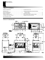
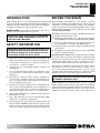
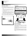
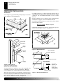
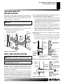
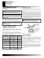
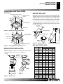
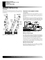
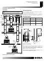
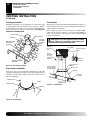
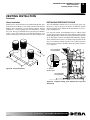
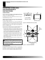
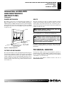
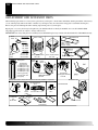
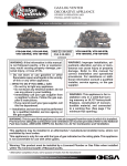
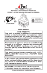
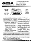
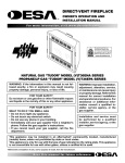
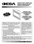
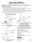
�������������������
����������������������
��������������������������
������������
��������������������������������������������
���������������
�����������������������
��������������
�����������������������������������������������
�������������������������������������������
�������������������������������������������������
������� ���� ��� ������� ������������ ������ ��
������������������������������������������
������������������������������������
��������� ��������� �������������� �������
������ ������������ ��������� ��� �����������
��������������������������������������������
�������������������������������������������������
������������������������������������������
��������������������������������������������
���������� ����������� �������� �������� ��� ���
�������������
���������������
��� ���� ������ ��� ���� ��������� ��� �����
��������������������������������������������
�������������������������������
�������������������������������������������
����������������������������������������������
��������������������������������������������
������ ������ ������ ������� ����������� ����
����������
���������������������������������������
�����������������������������������������
����������
��������������������������������������
�
�����������������
������������������
�����������������
PRODUCT DIMENSIONS ........................................................... 2
VENTING INSTALLTION ............................................................ 8
INTRODUCTION ......................................................................... 3
OPERATING GUIDELINES AND MAINTENANCE
SAFETY INFORMATION ............................................................ 3
INSTRUCTIONS ................................................................. 14
BEFORE YOU BEGIN ................................................................ 3
TECHNICAL SERVICE ............................................................. 15
FIREPLACE INSTALLATION ...................................................... 4
REPLACEMENT AND ACCESSORY PARTS ........................... 16
OUTSIDE AIR KIT INSTALLATION ............................................. 7
OWNER'S REGISTRATION FORM .......................................... 17
GAS LINE INSTALLATION ......................................................... 7
������������������
���
�����������������������������
��������������������������������������������
115607-01A
INTRODUCTION
SAFETY INFORMATION
BEFORE YOU BEGIN
INTRODUCTION
����� (�)PN36-A������������������������������������������������
���������������������������������������������������������������������
���������������������������������������������������������������������
�����������2���������������������������������� �������
������ ������ ���� ��������� ����� ����� ���������� ���� ����� ��
����������������������������������������������������
�����������������������������������������
������ ���� ����� ������������� ������� ���
������������������������
SAFETY INFORMATION
�������������������������������������������������
���������������������������������������������������������
��������������������������������������������������������
��������������������������������������� �����
��
��
��
��
��
��
��
��
�����������������������������������������������������������
��������������������������������������������������������������
��������������������������������������������������������������
�������������������������������������
������������������������������������������������������������
���������������
��� ���� ������� ����� ���������� ������ ���� ������������������
�������������������������������������������������������������
��������������
�����������������������������������������������������������������
���������������������������������������������������������������
��������������������������������������������������������������
�����������������������������������
��������������������������������������������������������������
��������������������������������������������������������������
��������������������������������������������������������������
�������������������������������������������������������������
��������������������������������������������������������������
��������������������
��������������������������������������������������������������
����������������������������������������������
�������������������������������������������������������������
���������������������������������������������������������
����������������������������������������������������������������
�������������������������������������������������������������
115607-01A
�
�
BEFORE YOU BEGIN
������� ���������� ���� ������������� ��� ����� ����������� ����� �����
������������� ������������ ����� ����� ���������� ���� ���� ��������
�����������������������������������������������������������������
�����������������������������������������������������������
�����������������������������������������������������������
��������������������
�����������������������������������������������������������
�����������������������������������������
�� ���������������������������������������������������������������
������������������������������������������������������������
�� �����������������������������������������������������������
��������������������������������������������������
�� ���������������������������������������������������������������
���������������
�� ������������������������������������������������������������
�������������������������������
����������������������������������������������������������
�������������������������������������������������������������������
���������������������������������������������������������������������
�������������������������������������������������������������������
����������������National Electrical Code, ANSI/NFPA 70-1990�
������������������������������������������������������������������
National Fire Protection Association Standard for Chimneys, Fireplaces, Vents and Solid-Fuel Burning Fireplaces, NFPA 211��������
����������������������������������BOCA Basic /National Code�����
Standard Mechanical Code����������Uniform Building Code�
��������������������������������������������
�������������������������
NOTE:� ������������� ���� ������� ������� ��� ����� ��� �� ���������
���������� ��������� ����� ���� ����������� ���� ���������� ���� �������
������������������������������������������������������������������
��������������������������������������������������������������������
�������������������������������������������������������������������
For more information, visit www.desatech.com
�
����������������������
������������������
����������
�����������������
����������������������
������������������
������������������������������������������������������������������
�����������������������������������������������������������������
�� ���������������������������������������������������������������
�������
�� ����������������������������������������������������������
�����������������������������������������������������������
�� �����������������������������������������������������������������
�������������������������
�� ������������������������������������������������������������������
������������������������������������������������������������
������������������������������������������������������������
�����������������������������������������������������
����������
����������������������������������
Back ............................................1/2" Min.
Adjacent Wall ............................. 12" Min.
Chimney Outer Pipe Surfaces ...... 2" Min.
Bottom Of Fireplaces To Floor ..... 0" Min.
�����������������������������������������������
����������� ��� ���� ������ ���������� ��� ���� ��������
������������������������������������������������������
��������������������������������������������������
������������������������������������������������
�������������������������������(�)PN3�-A����������������������������������
������� ���� ��� ������� ���� ���������� ���� ��������� ����� ���� ������ �
�������������������������������������������������������������������������
�������������������������������
���������������������������������������
�����L�����������
������������������������������������������������������������
����������� ������� ���� ��� ������� ������� �� ������� ��� ���� ���������
��������������������������
����������������������������������������������������������������
���������������������������������������������������������������������
����������������������������������������������������������������������
�������������������������
�����������������������������������������������������������������
�������������������������������������������������������������������
����������������������������������������������������������������������
����������
��������������������������������������������
115607-01A
����������������������
�������������������������
�������
�
�
����������������������
���������
5 /8" )
23 60cm
(
39 3/4"
(101cm)
Min.
4
(103 1/4
9.8 "
cm
)
��������������������������
����������������������������
�����������������������������
�������
���������������������������������������������������������������������������
�������������������������������������������������������������������
��������������������������������������������������������������������
��������������������������������������
����������������������������������������������������������������
������������������������������������������
������������������������������������������������������������������
����������� ����� ��� ������� �������� ������� ����������� ����� ����
�������� ���� ������� ������ ����� ��� ���� ���������� ��� �������� �������
�������� ������� ����� ������� ��� ����� ���� ��� ���� ���������� ��� ��� ��
���������� ��� �� ������� ���������� �� ��������� ������ ���������� ����
����������������������������������������������������������������������
������� ���� ���� ������ ���������� ������� ��� ����� ��� ��� �����
�����������������������������������������������������
���������������������������������������������������������
��������������������������������������������
115607-01A
�
����������������������
���������������
�����������������
����������������������
���������
����������������������������������������������������������������������
����������������������������������������
���������������������������������������������������������������������
��������������� ���������� ��������� ������� ���� �����������������
������������� ���� ��� ����� ���� ������� ����� ��� ������ ��� ���� ����
����������
��������������������������������������������������������������
��������������������������������������������������������
�����������������������������������������������������������������
�������������������������
����������������������������������������
����
�������������������������������������������������������������������
���������������������������������������������������
���������������������������
1/2" (1.27cm)
Minimum To
Combustibles
Nailing
Flanges
����������������������������
Prepared
Framing
Noncombustible
Hearth Extension
8" Max.
“Z” Type Ember Protector
1 1/2" Typ.
Noncombustible
Hearth Extension
Nails or
Screws
K Factor
.84
��������������������������
�����������������
�� ������� ���������� ��� ��������� ��� �������� ���� ������������ �����
������������������������������������������������������������
����������������������������������������������������������������
1 1/2" Typ.
For raised
fireplace, see
section on
framing with a
raised platform.
Ember Protector
����������������������������������������������������������������� �����������������������������������
�����������������������������������������������������������������
���������������������������������������������������������������������
���������������������������������������������������������
��������������������������������������������
115607-01A
OUTSIDE AIR KIT INSTALLATION
GAS LINE INSTALLATION
OUTSIDE AIR KIT
INSTALLATION
��������������������������������������������������������������������
������ �������� ��� ���� ���������� ���� ��� ���� ������� ��� ���� ���������
������������������������������������������������������������������
�������������������������������������
�����������������������������������������������
������������
��������������������������������������������������������������������
���������������������������������������������
����������������������������������������������������������������������
����������������������������������������������������
Secure Two Collars With
Duct Tape or Screws
Air Inlet
Termination
Air Inlet
Location
Must Allow
For Bushes
Or Snow
�
�
�������������������������������������������������
��������������������������������������
�� ������������������������������������������������������������
������������������������������������������������������������
����������������������������������������������������������������
���������������������������������������������������������������
���������������������������������������������
�� �������������������������������������������������������������������
���������������������������������������������������������������
�� ���������������������������������������������������������������
����������������������������������������������������������������
�����������������������������������������������������������������
�����������������������������������������������
Note:�������������������������������������������������������������
�����������������
�� ������������������������������������������������������������
�����������������������������������������������������������
������������������������������������������������������������
������������������������������������������������������������
Outside of
Fireplace
Gas Line
Conduit
Side Firebrick
Finished Side
Remove
Knockout
��������2�����������������������
GAS LINE INSTALLATION
����������������������������������������������
�����������������������������������������������������
�������� ������� ���� ��������� ����� ����
�����������������������
���������������������������������������������������������������������
���������� ����������� ���� ���������� ���������� �������� ����� �����
��������������������������������������������������������������
������������������������������������������������������������������������
�����������������������������
����������������������������������������������������������������������
���������������������������������������������������������������������
���������������������������������������������������������Standard for
Decorative Gas Appliances for Installation in Vented Fireplace,
ANSI Z21.60-1990����������������������������������
�������������������������������������������
Remove
Insulation
Temporarily
(Do Not
Discard)
Replace Screws After
Removing Gas Line
Cover Plate
��������3����������������������������������������������
Side Firebrick
Finished Side
Outside of
Fireplace
Gas Line
Conduit
Incoming
1/2" Black
Iron Pipe
Repack
Insulation
��������4�������������������
For more information, visit www.desatech.com
115607-01A
Refractory
Knockout Plug,
Remove by
Tapping Lightly
With A 1/2" Dowel
Provide Enough
Threaded End For
Fitting Connection
Seal Opening
With Refractory
Cement
8
GASLINE INSTALLATION
CHIMNEY PIPE INSTALLATION
PIPE INSTALLATION
FIRESTOP SPACERS
GAS LINE INSTALLATION
PIPE INSTALLATION
Continued
WARNING: After ensuring that the gas valve is ON,
test all gas piping and connections for leaks after
installing or servicing. Correct all leaks at once.
WARNING: Never use an open flame to check for
a leak. Apply a noncorrosive leak detection fluid to
all joints. Bubbles forming show a leak. Correct all
leaks at once.
Note: An appropriate DESA hood (see Replacement and Accessory
Parts, page 16) must be installed when using an unvented gas log set.
Place pipe assembly (inner and outer with wire spacer) over starter
collar. Inner pipe(s) fit inside inner pipe(s). Outer pipe fits outside
outer pipe.
Begin by aligning hemmed end of inner flue pipe into the inner starting
flue pipe of fireplace. Push down until hem “snap-locks” with lances. The
outer pipe is just the opposite, the female end has the lances. Continue the
same procedure for the outer pipe (see Figure 16). It is important to assure
the joints between the chimney sections are fully locked. Check by pulling
chimney upward after locking pipe hem(s). The chimney should not
come apart if properly locked. It is not necessary to add screws to keep
vertical or angled chimney runs together.
WARNING: The opening around the starter collar on
top of the fireplace must never be obstructed. Never use
blown insulation to fill the chimney enclosure.
CAUTION: When using a decorative appliance,
the damper must be removed or permanently locked
in the open position.
15" (381mm)
Galvanized
Outer Pipe
VENTING INSTALLATION
Hemmed
Ends
CHIMNEY PIPE INSTALLATION
The DESA chimney system is a snap-lock, double wall pipe. It
consists of a stainless steel inner flue pipe(s), a galvanized outer
pipe, and a wire spacer.
Each section of pipe comes in lengths of 12, 18, 36, and 48 inches,
but the actual lineal gain for each is measured after each section is
fully connected. Lineal gain is the actual measurable length of a part
after two or more parts are connected.
12 3/8" (314mm)
Stainless Inner
Pipe Lanced
Side Up
Figure 16 - Pipe Connection
MODEL NO.
DESCRIPTION
GAIN
FIRESTOP SPACERS
V3612ST
See-Through"
Fireplace
52 3/4"
48-12DM/48-12TM
Flue Pipe
46 5/8"
36-12DM/48-12TM
Flue Pipe
34 5/8"
Firestop spacers are required at each point where the chimney
penetrates a floor or ceiling joist space. Their purpose is twofold.
They establish and maintain the required clearance between the
outer pipe and combustible materials, they also serve as a shield
between floors as required by most codes.
24-12DM/48-12TM
Flue Pipe
22 5/8"
18-12DM/48-12TM
Flue Pipe
16 5/8"
12-12DM/48-12TM
Flue Pipe
10 5/8"
STL-12D
Chase Style
Termination
1" to 12"
RTL-12D
Round Top Termination
7"
When penetrating a floor or ceiling at an angle, use firestop spacer
number 30 FS-10D (see Replacement and Accessory Parts,
back page).
When the pipe passes through a framed opening into a living space
above, a firestop must be placed on the ceiling below (see Figure 17,
page 9). When the pipe passes through a framed opening into an attic
space above, a firestop must be placed on the attic floor above (see
Figure 18, page 9).
For more information, visit www.desatech.com
115607-01A
FIRESTOP SPACERS
ELBOW OFFSET INSTALLATION
SUPPORT SECTIONS
VENTING INSTALLTION
���������
Living Space Above Ceiling
����������������
Existing Ceiling
Frame
Firestop Spacer
�������������������������������������������������������������������������
�����������������������������������������������������������������������
����������������������������������������������������������������������
����������������19�������������������������������������������������������
������������������������������������������������������������������
������������������������������������������������������������������
���������������������������������������������������������0���� Rise
and Offset Chart ������
2" (5.1cm)
Minimum
Screw (8)
Angled Firestop
��������6�����������������������������������
Screw (8)
Ceiling Support
Firestop Spacer
Attic Space
Above Ceiling
B
Straps
Return
Elbow
��������7����������������������������������
Existing Ceiling
Frame
�����������������������������������������������������������������
�����������������������������������������������������8��
Strap
12S-12DM
Support
Required
���������������������
4 3/8
16 3/8
9 1/2
25 1/4
12 1/2
30 3/8
14 3/8
34
17 /8
39 /4
21 /2
46
22 /4
48 /8
26 /8
54 /8
26 /8
60
5
30 FT.
(9.14m)
3
3
3
��������������
��
��
��
Elbow Set Only
1
1
2
1
1
1
2
1
1
7
1
1
1
1
31 /4
63 /4
1
1
34 /4
69
1
1
38 /8
75 /8
39 /8
77 /8
1
43 /4
84 /2
1
46 /4
87 /4
48 /8
93 /8
3
5
7
3
3
��������8���������������
��
3
3
Return
Elbow
��������0������������������
������ 19�������������������
1
30 FT.
(9.14m)
A
�
�
�������� ������
�������������������������
115607-01A
�
�
7
2
5
7
1
1
2
3
3
1
2
For more information, visit www.desatech.com
1
1
10
SUPPORT SECTIONS
FINISHING YOUR CHIMNEY SYSTEM
10 Foot Rule
Minimum Chimney Height
Maximum Chimney Height
VENTING INSTALLTION
Continued
Maximum length of pipe between supports is 6 feet of angled run.
A maximum of two 6 foot angled run sections per chimney system
(See Figure 22).
IMPORTANT: If an exposed portion of chimney is greater than 4 feet
above the roof line, use support wires to keep chimney secure. The
support wires may be attached to the outer pipe of the chimney with
screws, provided the screws do not penetrate the inner flue pipe.
6’ MAX
(15.2cm)
6’ MAX
(15.2cm)
OFFSET
ELBOW
RETURN
ELBOW
CEILING
SUPPORT
PIPE
V12S-8DM
10 Foot Rule
All chimney terminations must extend a minimum of 3 feet above
the highest point where it passes through the roof, and must be at
least 2 feet above the roof within a 10 foot horizontal span (see
Figure 23).
RETURN
ELBOW
RETURN
ELBOW
FINISHING YOUR CHIMNEY SYSTEM
OFFSET
ELBOW
6’ MAX
(15.2cm)
RETURN
ELBOW
6’ MAX
(15.2cm)
6’ MAX
(15.2cm)
OFFSET
ELBOW
6’ MAX
(15.2cm)
Figure 23 - 10 Foot Rule
Minimum Chimney Height
Figure 22 - Typical Offset Installations
The minimum chimney height (measured from bottom of fireplace to
flue gas outlet-end of pipe) is 16 feet for a straight run, 16 feet minimum
for a run with 1 elbow set, and 25 feet minimum for a run with 2 elbow
sets. (A set consists of one starter elbow and one return elbow.)
Uncommon circumstances such as neighboring hills, tall trees, or
strong wind areas can cause down drafts in the chimney system. In
such cases going beyond the minimum recommended height would
be preferable to provide a better draw.
Maximum Chimney Height
The fireplace height approved for any chimney run with this
fireplace system is 40 feet measured from bottom of fireplace to flue
outlet-end of pipe. See Figure 24, page 11
For more information, visit www.desatech.com
115607-01A
11
11
FINISHING YOUR CHIMNEY SYSTEM
Maximum Chimney Height (Cont.)
Chimney Maintenance
VENTING INSTALLTION
Continued
Chimney Maintenance
WARNING: Do not operate an unvented gas log
set in this fireplace with the chimney removed.
RTL-12D
STL-12D
RTL-12D
Storm
Collar
Using Figure 24 and the roof opening chart below, determine the
opening that will be required for the pitch of your particular roof.
Roof Opening Chart
Flashing
Firestop
Spacer
Have your chimney system cleaned and inspected regularly to
ensure safe and efficient operation.
MINIMUM
HEIGHT
15 FT.
(4.5m)
MAXIMUM
HEIGHT
CHASE
TERMINATION
40 FT.
(12m)
PITCH
(degrees)
Opening “A”
Max. (inches)
Use Flashing
Model Number
FLAT
19
V6F-10DM
0-6/12
(26.6 deg. Slope)
23 /4
V6F-10DM
6/12-12/12
(56.3 deg. Slope)
30 3/4
V12F-10DM
1
19" Min.
(48.26cm)
2" Min.
(5.08cm)
30" Min.
(76.2cm)
2" Min.
(5.08cm)
Firestop
Spacer
2" Min.
(5.08cm)
30°
Firestop
Spacer
Opening
A
Figure 25 - Roof Opening
30° Offset/
Return
Before cutting hole, temporarily remove shingles around area to be
opened. After preparing the opening on the roof, continue to add
sections of pipe until it extends a minimum of 30 inches above
highest point of roof cutout (see Figure 25).
With the termination, the minimum height should add up to 3 feet
(see 10-Foot Rule and Figure 22, page 10).
Figure 24 - Maximum Chimney Height
For more information, visit www.desatech.com
115607-01A
��
FINISHING YOUR CHIMNEY SYSTEM
Flashing Installation
Storm Collar Installation
Terminations
VENTING INSTALLTION
���������
���������������������
������������
�������������������������������������������������������������������
���������������������������������������������������������������������
�������������������������������������������������������������������
������� ��� ��������� ��� �������� �������� ���������� ��� ���� ����
��������������������������������������������������������������������
�����������������������������������������������������������������������
�������������������������������
����������������������
Storm Collar
Chimney Pipe
Flashing
Overlap
Shingles
Top and
Sides
Only
Nail Only Outer
Perimeter of
Flashing
���� ������������� ��������� ���� ����� ���������� ���� �����2���
������ ���� ��� ����� ���� ���������� ��� ������ ���� S����2��� ���
��������������������������������������7���������������2��
����������������������
���������������������������������������������
���������� ������� ���� ������������� ������������� ����
��������������������������������������
Stainless
Inner Flue
Pipe
Secure
Termination
To Outer
Pipe With
3 Screws
RTL-12DM
Chase Top
1" Noncombustible
Spacer
Screen
Underlap Shingles
At Bottom
1" Space
��������5������������������������
Overlap Shingles
(Top and Sides)
of Flashing Base
�������������������������
Apply Waterproof
Caulking
Storm Collar
Flashing
������������������������������������������������������������������
����������������������������������������5������6�������������������
�����������������������������������������������������������������
���������������������
Underlap
Shingles
Chimney Pipe
Storm Collar
Caulk
��������7���������������
Flashing
��������6���������������
For more information, visit www.desatech.com
115607-01A
FINISHING YOUR CHIMNEY SYSTEM
Chase Installation
Installing Fireplace Facing
��
��
VENTING INSTALLTION
���������
������������������
���������������������������
����������������������������������������������������������������������
�������������������������������������������������������������������
��������� ������ �������������� �������� ��������� ��������� �������
���������������������������������������������������������������
������������������������������������������������������������������
�������������������������������������������������������������������
�������������������������������������������������������� ��������8��
���� ��������������� ��������� ���� ��� ����� ���� ������� �������� �����
��������������������������������������������������������������������
�����������������������������������������������������������Clearances�
�������������������29��
���� ����� ����� ����������� ��������������� ������� ��� ��������� ����
��������������������������������������������������������������������
���������������������������������������������������������������������������
����������������������������������������������������������������������
�����������������������������������������������������������������
�����������������������������������������������������������������������
����������������������������������������������������������������������
�����������������
18"
30"
MIN
.
30"
Noncombustible
Facing Material
MIN
.
TY
P.
MIN
.
��������8�������������������
“L” Shaped
Metal Support
Do Not
Block
Effective
Opening
Noncombustible
Facing Material
������ 29� �� ���������� ������� ������ ���������� ���� ����� ����
�������������
115607-01A
For more information, visit www.desatech.com
��
OPERATING GUIDELINE AND MAINTENANCE INSTRUCTIONS
Glass Doors
OPERATING GUIDELINES
AND MAINTENANCE
INSTRUCTIONS
�����������
����������������������������������(V)P��-A�����������������������
����� ��� �������� ����� ���� �������� ������ ������ ����� ����� �����
�����������������������������������������
�����������������������������������������������������������������������
���������������������������������
������������������������������������������������������������������
����������������������������������������������������������
���������������������0������1��
���������������������������������������������������������������
���������������������������������������������������������������������
�����������������������������������������������������������������
��������������������������������������������������������������������������
����������������������������
FULLY CLOSED
FIREPLACE FRONT
FULLY OPEN
FIREPLACE FRONT
��������0���������������������������������
�����������������������������������������������������������������������
�������������������������������������������������������������
� ��������������������������������������������������������������
������������������������������������������������������������������
������������������������������������������������������������������
����������������������������������������������������������������
������������������������������������������������������
� �������������������������������������������������������������
����������������������������������������������������������������
������ ������������ ������ ��� ����� ����� ������ ����� ���������� ��
������ ������ ������ ����� ���� ����� ���� �������� ������ �������� ��
�������������������������
� �������������������������������������������������������������
����������������������������
����������������������������������������������
����������������������������������������������������
�����������������������������������������������������
������������������������������������������������������
����������������������������
Side
Panel Is
Stationary
Glass Cabinet Doors
Operate Fully Open, or Fully
Closed ONLY
��������1�������������������������
������������������
����������������������������������������������������������������
�������������������������������������������������������������
���������������������������������������������������������������������
�����������������������������������������������������������������
For more information, visit www.desatech.com
115607-01A
OPERATING GUIDELINE AND MAINTENANCE INSTRUCTIONS
Damper Mechanism
Outside Air Mechanism
Grate
��
��
TECHNICAL SERVICE
OPERATING GUIDELINES
AND MAINTENANCE
INSTRUCTIONS
���������
����������������
�����
����������������������������������������������������������������
��������2��������������������������������������������������������
�������������������������������������������������������������
������������������������������������������������������������������
��������������������������������������������������������������������
������������������
����������������������������������������������������������������
������������������������������������������������������������������
������ ��������� ���� �� ����� �������� ��� ���� ��������� ���� ������ ��
������������������������������������������������������������������
����������������������������
GRATE
� ��������� ����� ��� ������ �������� ������ ����
�������������PN ��������������
�������������������������������������������������������������������
������������������������������������������������������������
DAMPER CONTROL LEVER
PULL DOWN TO CLOSE
PUSH UP TO OPEN
OUTSIDE AIR
HANDLE
PULL TO CLOSE
PUSH TO OPEN
�����������������������������������������������
���������������������������������������������������
����������������������������������������������������
�������������������������������������������������
��������������������������������������
�������������������������������������������������������������������
����������������������������������������������������������������
�������������
��������2�������������������
���������������������
�������������������������������������������������������������������������
�����������������������������2��������������������������������������
���������������������������������������������������������������
��������������������������������������������������������������
������������������������������������������������������������������
������������������������������������������������������������������
������������������
115607-01A
TECHNICAL SERVICE
����������������������������������������������������������������
����������������������������������������������������������������
���������������������������������������������������������������
������������������������������������
���� ���� ����� ������ ������� ���������� ��������� ���� ����� ��
�����������������
For more information, visit www.desatech.com
16
REPLACEMENT AND ACCESSORY PARTS
REPLACEMENT AND ACCESSORY PARTS
When ordering replacement or accessory items, please have your fireplace’s model name and number and the part number of the item(s)
you are ordering ready. The model name or number of your fireplace may be found on the rating plate located inside the fireplace.
Refer to the parts list and diagrams when ordering replacement parts for your fireplace.
Repair parts or accessory items may be bought from your distributor/dealer or directly from DESA. You can call 1-866-672-6040.
All product specifications are subject to change without notice.
IMPORTANT: Use of any other glass door assembly not tested with this fireplace may constitute a fire hazard and will void the DESA warranty.
Storm
Collar
Storm Collar
SC-10
Adjustable Hood
Flashing
6F-10DM
12F-10DM
18F-10DM
24F-10DM
Roof Pitch
0 to 6/12
6/12 to 12/12
12/12 to 18/12
18/12 to 24/12
Storm
Collar
Comes With
Wire Spacer
Black - 01244
Brass - 01245
Chrome - 01246
Round Top Termination
RTL-12D
Starter
Elbow
Double Wall
Chimney Pipe
12-12DM (12" Long)
18-12DM (18" Long)
24-12DM (24" Long)
36-12DM (36" Long)
48-12DM (48" Long)
Chimney pipe assy.
(includes outer and
inner pipes)
Econo Top Termination
STL-12D
Return
Elbow
Double Wall
30 ELBOW/OFFSET
30E-12D
Double Wall
PIpe Support Assembly
12S-12D
Double Wall Chimney Pipe(s) And Accessories Are Also Available In Triple Wall
OUTSIDE AIR KIT
AK-4
Vent
Hood
HEARTH
EXTENSION
KIT
HE-3610ST
16"
52 1/2"
Vent
Connector Duct - 4"x 3’
Plaster
Collar
Hearth
Extensions
(2)
Bi-Fold Door Set
GLASS DOORS
Hood Assembly
AK-V
Ember
Protectors (2)
Cabinet Door Set
For more information, visit www.desatech.com
115607-01A
��
��
OWNER'S REGISTRATION FORM
In order to provide better customer service for this and future purchases, we recommend that you register your product with us.
You can register online at www.desatech.com. If access to our website is not available to you, please complete this Owner’s
Registration Form and mail to the address on the back of this owner’s manual. Please provide the following product information:
Brand:
(Comfort Glow, Vanguard, etc.)
Model:
(EFP33PR, VTGH33NR, etc.)
Date Purchased:
Note: Keep receipt for warranty verification.
Serial Number:
7 or 9 digit number located on product or identification tag.
First Name:
Last Name:
Address:
State:
City:
Home Phone:
(
)
Zip:
Country:
-
E-Mail:
Please answer the following questions to register your product with DESA:
1.
Where will the product be used?
��Living/Family Room
��Utility Shed/Outbuilding
��Office/Warehouse
��Garage
��Bedroom
��Bathroom
2.
If you bought this product yourself, did you plan to purchase this type of product before going into the store?
3.
Who selected the product? � Male � Female � Both
4.
What is the population of your area? ��Under 10,000
��100,000 to 250,000
��10,000 to 25,000
What is your primary source of heat?
6.
How was the product installed? ��Professional Installer
7.
��Propane (LP Gas)
Cost of product excluding sales tax? $___________________
Cost to install product? $____________________
9.
Type of store where product was purchased? ��Hardware
��Fireplace or Hearth Shop
��Farm Store
��Fuel Oil
��Self
8.
��50,000 to 100,000
��Emergency Back-Up Heat
��Heater was on Sale
��Propane Dealer
��Electric
��Natural Gas/Utility Co.
��30 - 39
��Relative or Friend
��40 - 49
��50 - 59
��Completed College
��$15,000 to $19,999
��$20,000 to $34,999
��$100,000 and Over
16. In choosing this product, how important were the following:
Controls Location
Thermostat, Remote, or Manual Operation
Ease of Operation
Special Features
Salesperson’s Recommendation
Friend/Relative’s Recommendation
55253C
For more
Not Important
Somewhat Important
Very Important
�
�
�
�
�
�
�
�
�
�
�
�
�
�
�
�
�
�
�
�
�
�
�
�
�
�
�
�
�
�
�
�
�
�
�
�
�
�
�
�
�
�
�
�
�
�
information,
�
��Completed Graduate School
��60 or Over
City: _______________________ State: __________
Local Service
Value for Price
Prior Brand Experience
��Other
��Other ________________________
Name: ______________________________________
Overall Quality
Heat Output
Made in USA
Warranty
��Home Center/Builder’s Supply
��Construction Project
15. Store where product was purchased:
Availability
Price
Brand Name
��Other
��D.I.Y. Home Project
��Store Display
��Completed High School
14. Buyer’s total annual household income: ��Under $15,000
��$75,000 to $99,999
��Replace Older Model
��Energy Savings/High Efficiency
12. Level of Education of Purchaser: ��Some High School
��20 - 29
��Natural Gas
��Other
11. How did you learn about this product brand? ��Advertising
13. Age of Purchaser: ��Under 20
��Wood
��Other
10. What motivated you to buy this product? ��Sudden Cold Weather
Portability
Quiet Operation
��Yes ��No
��Over 250,000
5.
��$50,000 to $74,999
� 25,000 to 50,000
��Other
�
�
�
�
visit� www.desatech.com
�
�
��$35,000 to $49,999
TAPE
18
Postage
Required
2701 Industrial Drive
P.O. Box 90004
Bowling Green, KY 42102-9004
For more information, visit www.desatech.com
TAPE
55253C
19
19
NOTES
_______________________________________________________________________________________________
_______________________________________________________________________________________________
_______________________________________________________________________________________________
_______________________________________________________________________________________________
_______________________________________________________________________________________________
_______________________________________________________________________________________________
_______________________________________________________________________________________________
_______________________________________________________________________________________________
_______________________________________________________________________________________________
_______________________________________________________________________________________________
_______________________________________________________________________________________________
_______________________________________________________________________________________________
_______________________________________________________________________________________________
_______________________________________________________________________________________________
_______________________________________________________________________________________________
_______________________________________________________________________________________________
_______________________________________________________________________________________________
_______________________________________________________________________________________________
_______________________________________________________________________________________________
_______________________________________________________________________________________________
_______________________________________________________________________________________________
_______________________________________________________________________________________________
_______________________________________________________________________________________________
_______________________________________________________________________________________________
_______________________________________________________________________________________________
_______________________________________________________________________________________________
_______________________________________________________________________________________________
_______________________________________________________________________________________________
_______________________________________________________________________________________________
_______________________________________________________________________________________________
_______________________________________________________________________________________________
_______________________________________________________________________________________________
_______________________________________________________________________________________________
_______________________________________________________________________________________________
115607-01A
For more information, visit www.desatech.com
20
2701 Industrial Drive
P.O. Box 90004
Bowling Green, KY 42102-9004
115607-01
NOT A UPC
For more information, visit www.desatech.com
115607-01
Rev. A
08/05
55253C