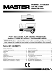
1
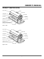
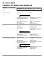
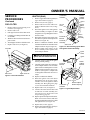
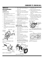
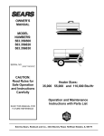
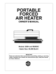
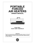
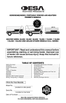
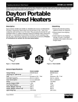
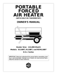
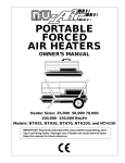
PORTABLE
FORCED
AIR HEATER
OWNER’S MANUAL
Heater Sizes:
RJ45 And RJ70
IMPORTANT: Read and understand this manual before assembling, starting,
or servicing heater. Improper use of heater can cause serious injury. Keep
this manual for future reference.
RJ45 And RJ70
PORTABLE FORCED AIR HEATERS
SAFETY
INFORMATION
WARNINGS
IMPORTANT: Read this Owner’s
Manual carefully and completely
before trying to assemble, operate, or service this heater. Improper use of this heater can
cause serious injury or death from
burns, fire, explosion, electrical
shock, and carbon monoxide
poisoning.
DANGER: Carbon monoxide
poisoning may lead to death!
Carbon Monoxide Poisoning: Early
signs of carbon monoxide poisoning resemble the flu, with headaches, dizziness,
and/or nausea. If you have these signs, the
heater may not be working properly. Get
fresh air at once! Have heater serviced.
Some people are more affected by carbon
monoxide than others. These include pregnant women, persons with heart or lung
disease or anemia, those under the influence
of alcohol, and those at high altitudes.
Make certain you read and understand all
Warnings. Keep this manual for reference.
It is your guide to safe and proper operation
of this heater.
• Use only kerosene or no. 1 fuel oil to
avoid risk of fire or explosion. Never use
gasoline, naphtha, paint thinner, alcohol,
or other highly flammable fuels.
• Fueling
a) Personnel involved with fueling shall
be qualified and thoroughly familiar
with the manufacturer’s instructions
and applicable governing regulations
regarding the safe fueling of heating
units.
b)Only the type of fuel specified on the
heater’s data plate shall be used.
c) All flame shall be extinguished
and the heater allowed to cool,
prior to fueling.
•
•
•
•
•
•
•
d)During fueling, all fuel lines and fuelline connections shall be inspected for
leaks. Any leaks shall be repaired prior
to returning the heater to service.
e) At no time shall more than one day’s
supply of heater fuel be stored inside
a building in the vicinity of the heater.
Bulk fuel storage shall be outside the
structure.
f) All fuel storage shall be located a
minimum of 8 meters from heaters,
torches, welding equipment, and
similar sources of ignition (exception: the fuel reservoir integral with
the heater unit).
g)Whenever possible, fuel storage shall
be confined to areas where floor penetrations do not permit fuel to drip
onto or be ignited by a fire at lower
elevation.
h)Fuel storage shall be in accordance
with the authority having jurisdiction.
Never use heater where gasoline, paint
thinner, or other highly flammable vapors are present.
Follow all local ordinances and codes
when using heater.
Heaters used in the vicinity of tarpaulins, canvas, or similar enclosure materials shall be located a safe distance
from such materials. The recommended
minimum safe distance is 3 meters. It
is further recommended that these enclosure materials be of a fire retardant
nature. These enclosure materials shall
be securely fastened to prevent them
from igniting or from upsetting the
heater due to wind action.
Use only in well-vented areas. Before
using heater, provide at least a 2800
square-centimeter opening of fresh,
outside air for each 25,000 Kcal/Hr of
rating.
Use only in places free of flammable
vapors or high dust content.
Use only the electrical voltage and frequency specified on model plate.
Use only a three-prong, grounded extension cord.
2
•
•
•
•
•
•
•
•
•
•
Minimum heater clearances from combustibles:
Outlet: 2.5 meters
Sides: 1.25 meters
Top: 1.25 meters
Rear: 1.25 meters
Locate heater on a stable and level surface if heater is hot or running or a fire
may occur.
When moving or storing heater, keep
heater in a level position or fuel spillage may occur.
Keep children and animals away from
heater.
Unplug heater when not in use.
When used with thermostat, heater may
start anytime.
Never use heater in living or sleeping
areas.
Never block air inlet (rear) or air outlet
(front) of heater.
Never move, handle, refuel, or service
a hot, operating, or plugged-in heater.
Never attach duct work to front or rear
of heater.
UNPACKING
1.
2.
3.
Remove all packing items applied to
heater for shipment.
Remove all items from carton.
Check items for shipping damage. If
heater is damaged, promptly inform
dealer where you bought heater.
104950
OWNER’S MANUAL
PRODUCT IDENTIFICATION
Hot Air Outlet
Handle
Upper Shell
Lower Shell
Fan Guard
Fuel Gauge
Air Filter
End Cover
Fuel Tank
ON/OFF Switch
Fuel Cap
Side Cover
Receptacle
Ignition Control Assembly
(assembly on inside of side cover)
Power Cord
Figure 1 - RJ45
Hot Air Outlet
Handle
Lower Shell
Upper Shell
Fuel Gauge
Fan Guard
Fuel Tank
Air Filter
End Cover
Receptacle
Fuel Cap
Side Cover
ON/OFF Switch
Flame-Out Control Reset Button
Power Cord
Figure 2 - RJ70
104950
3
RJ45 And RJ70
PORTABLE FORCED AIR HEATERS
THEORY OF OPERATION
The Fuel System: The air pump forces air
through the air line. The air is then pushed
through the nozzle. This air causes fuel to
lift from the tank. A fine mist of fuel is
sprayed into the combustion chamber.
The Air System: The motor turns the fan.
The fan pushes air into and around the
combustion chamber. This air is heated and
provides a stream of clean, hot air.
FUELS
The Ignition System (RJ45): The ignition control assembly provides power to the
ignitor. This ignites the fuel/air mixture in
the combustion chamber.
The Ignition System (RJ70): The electronic ignitor sends voltage to the spark
plug. The spark plug ignites the fuel and air
mixture.
The Flame-Out Control System: This
system causes the heater to shut down if the
flame goes out.
Combustion Chamber
Motor
Ignitor or
Spark Plug
Air Pump
Air Intake
Filter
Fan
Clean
Heated
Air Out
Cool
Air In
Air
Output
Filter
Fuel
Tank
Nozzle
Fuel
Filter
Air For Fuel
System
Air Line
To Burner
Air For Combustion
And Heating
Ignition
Control
Assembly or
Electronic
Ignitor
Fuel
Figure 3 - Cross Section Operational View
WARNING: Use only kerosene
or no. 1 fuel oil to avoid risk of fire
or explosion. Never use gasoline,
naphtha, paint thinners, alcohol,
or other highly flammable fuels.
Do not use heavy fuels such as diesel. Using
heavy fuels will result in:
• clogged fuel filter and nozzle
• the need of nontoxic anti-icer in fuel during very cold weather
IMPORTANT: Use a KEROSENE ONLY
storage container. Be sure storage container is
clean. Foreign matter such as rust, dirt, or
water will cause the control to shut down the
heater. Foreign matter may also require you to
clean fuel system often.
VENTILATION
WARNING: Follow the minimum fresh, outside air ventilation requirements. If proper fresh,
outside air ventilation is not provided, carbon monoxide poisoning can occur. Provide proper
fresh, outside air ventilation before running heater.
Provide at least a 2800 square-centimeter
opening of fresh, outside air for each 25,000
Kcal/Hr rating. Provide extra fresh air if
more heaters are being used.
Example:
The RJ45 (11,900 Kcal/Hr) heater requires
a 1400 square-centimeter opening of fresh
outside air.
The RJ70 (17,600 Kcal/Hr) heater requires
a 2000 square-centimeter opening of fresh
outside air.
4
104950
OWNER’S MANUAL
OPERATION
WARNING: Review and understand the warnings in the
Safety Information section, page
2. They are needed to safely operate this heater. Follow all local
codes when using this heater.
TO START HEATER
1.
2.
3.
4.
Follow all ventilation and safety information.
Fill fuel tank with kerosene or no. 1
fuel oil.
Attach fuel cap.
Plug power cord of heater into
grounded extension cord. Extension
cord must be at least 2 meters long.
Extension Cord Wire Size
Requirements
• 2 to 3 meters long, use 1 mm2 cord
• 3 to 30 meters long, use 1.5 mm2 cord
• 30 to 60 meters long, use 2 mm2 cord
PREVENTATIVE
MAINTENANCE
SCHEDULE
5.
6.
Plug extension cord into standard 100
volt/50 or 60 hertz grounded outlet.
Switch heater ON.
RJ45 Note: Ignitor will preheat for
five seconds, then heater will start.
RJ70 Note: If heater will not start,
push in flame-out control reset button
(see Figure 2, page 3).
TO STOP HEATER
1.
2.
Switch heater OFF.
Unplug extension cord from outlet.
TO RESTART HEATER
1.
2.
Switch heater OFF. Wait 10 seconds
(two minutes if heater has been running).
Switch heater ON.
RJ45 Note: Ignitor will preheat for
five seconds then heater will start.
RJ70 Note: If heater will not start,
push in flame-out control reset button
(see Figure 2, page 3).
STORING,
TRANSPORTING,
OR SHIPPING
Note: If shipping, transport companies require fuel tanks to be empty.
1. Drain fuel tank. Drain fuel through
drain-plug under tank. Be sure all fuel
is removed.
2. If any debris is noted in old fuel, add 1
or 2 liters of clean kerosene to tank, stir,
and drain again. This will prevent excess debris from clogging filters during future use.
3. Replace fuel cap. Properly dispose of old
and dirty fuel. Check with local automotive service stations that recycle oil.
4. If storing, store heater in dry place.
Make sure storage place is free of dust
and corrosive fumes.
IMPORTANT: Do not store kerosene over
summer months for use during next heating
season. Using old fuel could damage heater.
WARNING: Never service heater while it is plugged in, operating, or
hot. Severe burns and electrical shock can occur.
Item
How Often
How To
Fuel tank
Flush every 150-200 hours of operation or
as needed
See Storing, Transporting, or Shipping,
above
Air output and lint filters
Replace every 500 hours of operation or
once a year
See Air Output, Air Intake, and Lint Filters,
page 8
Air intake filter
Wash and dry with soap and water every
500 hours of operation or replace as needed
See Air Output, Air Intake, and Lint Filters,
page 8
Fuel filter
Clean twice a heating season or replace as
needed
See Fuel Filter, page 9
RJ45: Ignitor
No maintenance required
RJ70: Spark Plug
Clean and regap every 600 hours of operation or replace as needed
See Spark Plug, page 10
Clean each season or as needed
See Fan, page 8
Fan blades
Motor
Not required/permanently lubricated
104950
5
RJ45 And RJ70
PORTABLE FORCED AIR HEATERS
TROUBLESHOOTING
WARNING: Never service heater while it is plugged in, operating, or
hot. Severe burns and electrical shock can occur.
RJ45
OBSERVED FAULT
POSSIBLE CAUSE
REMEDY
Motor does not start five seconds after heater
is plugged in and switched ON
1. No power to heater
1. Check circuit breaker in electrical panel
WARNING: High voltage!
2. Bad electrical connection between motor and ignition control assembly or ignition assembly and power cord
3. Binding pump rotor
Motor starts and runs but heater does not
ignite
2. Check all electrical connections. See
Wiring Diagrams, page 12
4. Defective ignition control assembly
5. Defective motor
6. Defective ON/OFF switch
3. If fan does not turn freely, see Pump Rotor, page 11
4. Replace ignition control assembly
5. Replace motor
6. Replace ON/OFF switch
1.
2.
3.
4.
5.
1.
2.
3.
4.
5.
No fuel in tank
Pump pressure incorrect
Dirty fuel filter
Obstruction in nozzle
Water in fuel tank
Fill tank with kerosene
See Pump Pressure Adjustment, page 8
See Fuel Filter, page 9
See Nozzle, page 10
Drain and flush fuel tank with clean
kerosene. See Storing, Transporting, or
Shipping, page 5
WARNING: High voltage!
Heater ignites but ignition control assembly
shuts heater off after a short period of time
6. Bad electrical connection between ignitor and ignition control assembly
7. Defective ignitor
8. Defective ignition control assembly
6. Check electrical connections. See Wiring Diagrams, page 12
7. Replace ignitor, see page 9
8. Replace ignition control assembly
1. Pump pressure incorrect
2. Dirty air intake, air output, and/or lint
filter
3. Dirty fuel filter
4. Obstruction in nozzle
5. Photocell assembly not properly installed (not seeing the flame)
6. Dirty photocell lens
1. See Pump Pressure Adjustment, page 8
2. See Air Output, Air Intake, and Lint Filters, page 8
3. See Fuel Filter, page 9
4. See Nozzle, page 10
5. Make sure photocell boot is properly
seated in bracket
6. Clean photocell lens
WARNING: High voltage!
7. Bad electrical connection between photocell and ignition control assembly
8. Defective photocell
9. Defective ignition control assembly
6
7. Check electrical connections. See Wiring Diagrams, page 12
8. Replace photocell
9. Replace ignition control assembly
104950
OWNER’S MANUAL
TROUBLESHOOTING
WARNING: Never service heater while it is plugged in, operating, or
hot. Severe burns and electrical shock can occur.
Continued
RJ70
OBSERVED FAULT
POSSIBLE CAUSE
REMEDY
Heater ignites, but flame-out control shuts
off heater after a short period of time
1. Photocell assembly not properly installed (seeing flame)
2. Wrong pump pressure
3. Dirty air output, air intake and lint filters
1. Make sure photocell boot is properly
seated in bracket
2. See Pump Pressure Adjustment, page 8
3. See Air Output, Air Intake and Lint Filters, page 8
4. See Fuel Filter, page 9
5. See Nozzle, page 11
6. Clean photocell lens
7. Replace flame-out control
8. Replace photocell
4.
5.
6.
7.
8.
Heater will not ignite, but motor runs for a
short period of time
Dirty fuel filter
Dirt in nozzle
Dirty photocell lens
Defective flame-out control
Defective photocell
1. No fuel in tank
2. Wrong pump pressure
3. Carbon deposits on spark plug and/or
improper gap
4. Dirty fuel filter
5. Dirt in nozzle
6. Water in fuel tank
1. Fill tank with kerosene
2. See Pump Pressure Adjustment, page 8
3. See Spark Plug, page 10
4. See Fuel Filter, page 9
5. See Nozzle, page 11
6. Drain and flush fuel tank with clean
kerosene. See Storage, Transporting, or
Shipping,page 5
WARNING: High voltage!
7. Electronic ignitor not grounded
8. Defective electronic ignitor
Motor does not start when heater is plugged
in and switched ON, fan rotates slowly or
does not turn
1. Flame-out control not reset
2. Binding pump rotor
3.
4.
5.
6.
104950
Defective motor
Defective ON/OFF switch
No power to heater
Bad electrical connections
7
7. Make sure electronic ignitor mounting
is tight
8. Replace electronic ignitor
1. Press flame-out control reset button
2. If fan is hard to turn, see Pump Rotor,
page 11
3. Replace motor
4. Replace ON/OFF switch
5. Check circuit breaker in electrical panel
6. Check all electrical connections. See
Wiring Diagrams, page 12
RJ45 And RJ70
PORTABLE FORCED AIR HEATERS
PUMP PRESSURE
ADJUSTMENT
SERVICE
PROCEDURES
Fan
1.
Motor
WARNING: Never service
heater while it is plugged in, operating, or hot. Severe burns and
electrical shock can occur.
2.
3.
Flush
4.
UPPER SHELL REMOVAL
1.
2.
3.
Motor
Shaft
Remove screws along each side of
heater using 5/16" nut-driver. These
screws attach upper and lower shells
together.
Lift upper shell off.
Remove fan guard.
Setscrew
Figure 5 - Fan Cross Section
Upper Shell
Fan
Guard
AIR OUTPUT, AIR INTAKE,
AND LINT FILTERS
1.
2.
3.
4.
5.
Figure 4 - Upper Shell Removal
FAN
IMPORTANT: Remove fan from motor
shaft before removing motor from heater.
The weight of the motor resting on the
fan could damage the fan pitch.
1. Remove upper shell (see above).
2. Use 1/8" Allen wrench to loosen setscrew which holds fan to motor shaft.
3. Slip fan off motor shaft.
4. Clean fan using soft cloth moistened
with kerosene or solvent.
5. Dry fan thoroughly.
6. Replace fan on motor shaft. Place
fan hub flush with end of motor
shaft (see Figure 5).
7. Place setscrew on flat of shaft.
Tighten setscrew firmly (7200-8900
grams/centimeter).
8. Replace fan guard and upper shell.
6.
7.
Remove upper shell (see Upper Shell
Removal).
Remove filter end cover screws using
5/16" nut-driver.
Remove filter end cover.
Replace air output and lint filters.
Wash or replace air intake filter (see
Preventative Maintenance Schedule,
page 5).
Replace filter end cover.
Replace fan guard and upper shell.
IMPORTANT: Do not oil filters.
5.
Remove pressure gauge plug from filter
end cover.
Install accessory pressure gauge (part
number HA1180).
Start heater (see Operation, page 5). Allow motor to reach full speed.
Using a flat blade screwdriver, adjust
pressure. Turn relief valve to right to
increase the pressure. Turn relief valve
to left to decrease the pressure. Set
pump pressure as follows:
RJ45: 0.22 kg/cm2 at 50 Hz.
0.24 kg/cm2 at 60 Hz.
RJ70: 0.35 kg/cm2 at 50 Hz.
0.38 kg/cm2 at 60 Hz.
Remove pressure gauge. Replace pressure gauge plug in filter end cover.
Pressure
Gauge
Plug
Relief Valve
Figure 7 - Pressure Gauge Plug Removal
Air Intake Filter
Filter End Cover
Fan Guard
Pressure
Gauge
Lint Filter
Air Output Filter
Figure 6 - Air Output, Air Intake, and Lint
Filters
Figure 8 - Adjusting Pump Pressure
8
104950
OWNER’S MANUAL
SERVICE
PROCEDURES
Continued
2.
3.
4.
5.
6.
7.
1.
Remove upper shell and fan guard (see
Upper Shell Removal, page 8).
Remove fan (see Fan, page 8).
Remove side cover screws with a 5/16"
nut driver. Remove side cover (see Figure 9).
Disconnect ignitor wires from ignition
control assembly (see Figure 10). Pull
the ignitor wires up through the hole in
the lower shell.
Disconnect fuel line hose and air line
hose. Remove photocell from photocell
bracket (see Figure 10).
Remove combustion chamber. Stand
combustion chamber on end with nozzle
adapter bracket on top (see Figure 11).
Remove ignitor screw with a 1/4" nut
driver. Carefully remove ignitor from
nozzle adapter bracket.
2.
3.
FUEL FILTER
1.
IGNITOR (RJ45)
Remove side cover screws using 5/16"
nut-driver (see Figure 9).
Remove side cover.
Pull upper fuel line off fuel filter neck.
Carefully pry bushing and fuel filter out
of fuel tank.
Wash fuel filter with clean fuel and replace in tank.
Attach upper fuel line to fuel filter neck.
Replace side cover (see Figure 9).
4.
5.
6.
7.
Fuel Filter
Combustion
Chamber
Nozzle
Adapter
Bracket
Ignitor
Air Line
Hose
Ignitor
Wires
(Gray)
Fuel
Line
Hose
Ignition
Control
Assembly
Photocell
Bracket
Photocell
Assembly
Side Cover
Figure 10 - Disconnecting Ignitor Wires
from Ignition Control Assembly
Ignitor
Screw
CAUTION: Do not bend or strike
ignitor element. Handle with care.
8.
9.
Side Cover
Upper Fuel Line
Figure 9 - Fuel Filter Removal
10.
11.
12.
13.
14.
15.
16.
Carefully remove replacement ignitor
from styrofoam packing.
Carefully guide ignitor into opening in
nozzle adapter bracket. Do not strike
ignitor element. Attach ignitor to nozzle
adapter bracket with screw using a 1/4"
nut driver (see Figure 11). Torque 1800
to 3500 grams/centimeters. Do not over
torque.
Replace combustion chamber.
Route the ignitor wires back down
through the hole in the lower shell.
Connect wires to the ignition control
assembly. See Wiring Diagrams, page
12, for correct terminal locations.
Replace side cover (see Figure 9).
Connect and route fuel line hose and
air line hose to nozzle assembly. See
Fuel and Air Line Replacement and
Proper Routing, page 10.
Replace photocell in photocell bracket.
Route wires between hoses and back
down through the hole in the lower shell
with ignitor wires (see Figure 10).
Replace fan (see Fan, page 8).
Replace fan guard and upper shell (see
Upper Shell Removal, page 8).
Ignitor
Photocell
Bracket
Combustion
Chamber
Ignitor
Element
Nozzle
Adapter
Bracket
Nozzle Adapter
Bracket Opening
Figure 11 - Ignitor Replacement
Continued
104950
9
RJ45 And RJ70
PORTABLE FORCED AIR HEATERS
SERVICE
PROCEDURES
9.
Continued
10.
SPARK PLUG (RJ70)
1.
2.
3.
4.
5.
6.
7.
8.
9.
Remove upper shell (see Upper Shell
Removal, page 8).
Remove fan (see Fan, page 8).
Remove spark plug wire from spark plug.
Remove spark plug from burner head
using 13/16" open-end wrench.
Clean and regap spark plug electrodes
to 2.2 mm.
Install spark plug in burner head.
Attach spark plug wire to spark plug.
Replace fan (see Fan, page 8).
Replace fan guard and upper shell (see
Upper Shell Removal, page 8).
Burner
Head
11.
12.
13.
Screw nozzle into nozzle adapter until
nozzle seats. Tighten 7200-8000 grams/
centimeter using 5/8" socket wrench.
Install nozzle adapter into nozzle
adapter bracket.
Connect and route fuel line hose and
air line hose to nozzle assembly. See
Fuel and Air Line Replacement and
Proper Routing, page 10.
Replace fan (see Fan, page 8).
Replace fan guard and upper shell (see
Upper Shell Removal, page 8).
FUEL AND AIR LINE
REPLACEMENT AND
PROPER ROUTING
1.
2.
3.
4.
Combustion
Chamber
Fuel Line
Hose
Nozzle
Adapter
Air Line
Hose
5.
Ignitor and
Photocell
wires
through
this hole
Spark Plug Wire
Figure 14 - Removing Air and Fuel Line
Hoses
Spark Plug
Combustion
Chamber
Figure 12 - Spark Plug Removal
Bend Here to Adjust Gap
Gap
2.2 mm
Nozzle
Adaptor
Bracket
Nozzle
Adapter
Figure 13 - Spark Plug Gap
6.
7.
Remove upper shell (see Upper Shell
Removal, page 8).
Remove side cover screws using 5/16"
nut driver (see Figure 9, page 9).
Remove side cover.
Inspect fuel and air line hoses for cracks
and/or holes. If fuel line hose is damaged, disconnect from nozzle adapter or
burner head (see Figure 14 or Figure 18,
page 11) and from fuel filter (see Fuel
Filter, page 9). If air line hose is damaged, disconnect from nozzle adapter or
burner head (see Figure 14 or Figure 18,
page 11) and from barb fitting on pump
end cover (see Figure 17).
Install new air and/or fuel line. Attach
one end of air line hose to barb fitting
on pump end cover (see Figure 17) and
the other end to nozzle adapter or
burner head (see Figure 14 or Figure
18, page 11). Attach one end of fuel line
hose to fuel filter (see Fuel Filter, page
9) and the other end to nozzle adapter
(see Figure 14 or Figure 18, page 11).
Route air and fuel line approximately
as shown in Figure 14 (RJ45) or 18
(RJ70), page 11.
Note: Hoses are not to touch photocell
bracket.
Replace side cover.
Replace upper shell and fan guard (see
Upper Shell Removal, page 8).
NOZZLE (RJ45)
1.
2.
3.
4.
5.
6.
7.
8.
Remove upper shell (see Upper Shell
Removal, page 8).
Remove fan (see Fan, page 8).
Remove fuel and air line hoses from
nozzle adapter.
Turn nozzle adapter 1/4 turn to left and
pull toward motor to remove.
Place nozzle adapter into vise and
lightly tighten.
Carefully unscrew nozzle from the
nozzle adapter using 5/8" socket wrench.
Blow compressed air through face of
nozzle. This will free any dirt in
nozzle area.
Inspect nozzle seal for damage.
Pump End Cover
Figure 15 - Removing Nozzle Assembly
Nozzle Face
Nozzle Seal
Barb
Fitting
Nozzle
Air Hose
Nozzle Adapter
Air Line
Fitting
Figure 17 - Air Hose to Barb Fitting
Fuel Line
Fitting
Figure 16 - Nozzle and Nozzle Adapter
10
104950
OWNER’S MANUAL
SERVICE
PROCEDURES
9.
Continued
10.
11.
NOZZLE (RJ70)
1.
2.
3.
4.
5.
6.
7.
8.
Remove upper shell (see Upper Shell
Removal, page 8).
Remove fan (see Fan, page 8).
Remove fuel and air line hoses from
burner head.
Remove spark plug wire from spark
plug.
Remove spark plug from burner head
using 13/16" open-end wrench.
Remove three screws using 5/16" nutdriver and remove burner head from
combustion chamber.
Place burner head into vise and lightly
tighten.
Carefully remove nozzle from burner
head using 5/8" socket wrench (see Figure 19).
Burner Head
Combustion
Chamber
Screw
12.
13.
14.
15.
16.
17.
Spark Plug
Fuel Line Hose
Air Line
Hose
1.
3.
4.
5.
6.
7.
8.
9.
Nozzle Face
Nozzle Seal
Remove upper shell (see Upper Shell
Removal, page 8).
Remove filter end cover screws using
5/16" nut-driver.
Remove filter end cover and air filters.
Remove pump plate screws using 5/16"
nut-driver.
Remove pump plate.
Remove rotor, insert, and blades.
Check for debris in pump. If debris is
found, blow out with compressed air.
Install insert and rotor.
Check gap on rotor. Adjust to
0.08/0.10 mm if needed (see Figure 21).
Note: Rotate rotor one full turn to insure the gap is 0.08/0.10 mm at tightest position. Adjust if needed.
Blade
Pump Plate
Air Intake Filter
Filter End
Cover
Nozzle
Fuel Line
Fitting
Air Line Fitting
Figure 19 - Removing Nozzle
Insert
Rotor
Air Output
Filter
OTOR
PFA/P 056
Fan Guard
Figure 20 - Rotor Location
104950
Gap Adjusting Screw
Blade
(Procedure if Rotor is Binding)
Figure 18 - Removing Burner Head
Burner Head
10. Install blades, pump plate, air filters,
and filter end cover.
11. Replace fan guard and upper shell.
12. Adjust pump pressure (see Pump Pressure Adjustment, page 8).
Note: If rotor is still binding, proceed
as follows.
13. Perform steps 1 through 6, column 1.
14. Place fine grade sandpaper (600 grit) on
flat surface. Sand rotor lightly in “figure
8” motion four times (see Figure 22).
15. Reinstall insert and rotor.
16. Perform steps 10 through 12.
PUMP ROTOR
2.
Spark
Plug
Wire
Blow compressed air through face of
nozzle. This will free any dirt in
nozzle area.
Inspect nozzle seal for damage.
Replace nozzle into burner head and
tighten firmly (14,300-19,600 grams/
centimeter).
Attach burner head to combustion
chamber.
Install spark plug in burner head.
Attach spark plug wire to spark plug.
Connect and route fuel line hose and
air line hose to burner head. See Fuel
and Air Line Replacement and Proper
Routing, page 10.
Replace fan (see Fan, page 8).
Replace fan guard and upper shell (see
Upper Shell Removal, page 8).
11
0.08/0.10 mm
Gap Measured
With Feeler
Gauge
Rotor
Gap Adjusting Screw
Figure 21 - Gap Adjusting Screw Locations
Sandpaper
Figure 22 - Sanding Rotor
RJ45 And RJ70
PORTABLE FORCED AIR HEATERS
WIRING DIAGRAMS
Orange
Ignitor
Power Plug
100V/50 or 60 Hz
Orange
IGNITOR
Red
MOTOR MAIN
Ignition Control
Assembly
Motor Green
Black
Green
White
Black
ON/OFF
Switch
Receptacle
120V (L1)
Black
AC NEUTRAL (L2)
MOTOR RETURN
White
Photocell
Blue
PHOTOCELL
Blue
PHOTOCELL
104040
IGNITOR
Figure 22- Wiring Diagram For RJ45
Power Plug
100V/50 or 60 Hz
Green
White
Plug
Black
Black
Power On Switch
Receptacle
Black
White
White
White
Motor
Green/
Yellow
Green
Ignitor
Spark Plug
Red
B
White Photo- Blue Blue FlameOut
cell
Control
Terminal
Board
Red
R
Reset
Button
Red
Black
Relay
Red
Figure 23- Wiring Diagram For RJ70
12
104950
OWNER’S MANUAL
SPECIFICATIONS
Maximum Output Rating (Kcal/Hr)
Fuel
Fuel Tank Capacity (liters)
Fuel Consumption (liters/Hr)
Electric Requirements
Amperage (Normal Run)
Motor Speed (RPM at 50/60 Hz)
Motor Watts
Pump Pressure (kg/cm2 at 50/60 Hz)
RJ45
RJ70
11,900
17,600
Use Only Kerosene or No. 1 Fuel Oil
15.1
18.9
1.3
1.9
100V/50 or 60 Hz
3.7
3.0
2850/3450
2850/3450
93
93
0.22/0.24
0.35/0.38
ACCESSORIES
Purchase accessories and parts from your
nearest dealer.
A 008
AIR GAUGE KIT - HA1180
Special tool to check pump pressure.
IGNITION CONTROL
ASSEMBLY/PHOTOCELL
TESTER - HA1170
Special tool used to test the ignition control
assembly and photocell.
HEAVY DUTY WHEELS AND
HANDLE KIT - HA1202
For heavy duty applications. Makes your
heater even more portable and convenient.
104950
13
RJ45 And RJ70
PORTABLE FORCED AIR HEATERS
ILLUSTRATED
PARTS BREAKDOWN
4
1
RJ45
2
5
9-1
36
9-2
9-5
3
9
7
6
11
9-4
9-3
8
21
10
12
18
13
20
22
16
23
24
25
28
42
26
27
30
29
35
37
34
12-1
19
12-2
17
12-3
15
41
12-4
40
12-18
12-17
39
33
32
14
31
38
12-7
12-16
12-8
12-5
12-6
12-9
12-15
Motor and Pump Assembly
12-13
12-11
12-14
12-10
12-12
14
104950
OWNER’S MANUAL
PARTS LIST
This list contains replaceable parts used in your heater. When ordering parts, be sure to provide the correct
model and serial numbers (from the model plate), then the part number and description of the desired part.
RJ45
KEY
NO.
PART
NUMBER
DESCRIPTION
1
2
3
4
5
6
7
8
9
9-1
9-2
9-3
9-4
9-5
10
11
12
12-1
12-2
12-3
12-4
12-5
12-6
12-7
12-8
12-9
12-10
12-11
12-12
12-13
12-14
12-15
12-16
12-17
M51104-01
098511-36
M11084-29
100647-01
098512-62
M10908-2
103154-03
M16656-23
∆
100735-22
102548-04
104056-01
102336-01
104023-01
M11084-26
097033-01
∆
102001-22
079975-02
M22009**
M22456-1**
M29608
M29632 ⊕
M29633 ⊕
M29609
M12461-31
M27694 ∞
M10993-1 ∞
M22997 ∞
M8940 ∞
M29612-01 ⊕
M12461-31
103676-01
M8643**
Handle
Upper Shell
Screw, #10-16 x 3/4"
Screw, #10-16 x 1/2"
Combustion Chamber
Screw, #6-32 x 3/8"
Photocell Bracket
Photocell Assembly
Burner Head Assembly
Nozzle Assembly
Ignitor Kit
Nozzle Adapter
Nozzle Adapter Bracket
Screw/Washer Assembly
Screw, #10-16 x 3/8"
Fan
Motor and Pump Assembly
Motor
Pump Body
Insert
Rotor
Pump End Cover
Lint Filter
Intake Filter
Filter End Cover
Screw, #10-32 x 1"
Adjusting Screw
Pressure Relief Spring
Plug
Steel Ball, 1/4" Diameter
Output Filter
Screw, #10-32 x 1"
Nylon Elbow, 90°
Blade
∆
**
⊕
∞
QTY.
1
1
2
6
1
2
1
1
1
1
1
1
1
1
2
1
1
1
1
1
1
1
1
1
1
3
1
1
1
1
1
6
1
4
PART
NUMBER
DESCRIPTION
12-18
13
14
15
16
17
18
19
20
21
22
23
24
25
26
27
28
29
30
31
32
33
34
35
36
37
38
39
40
41
42
FHPF3-5C
M51105-01
102330-01
099492-01
NTC-4C
M11084-26
M50631
097461-06AA
101205-01
M30865-02
M11271-8
M50104-02
M11084-26
M10908-14
098511-18
M50814-06
079973-01
M50876-02
M10990-3
101695-01
102349-01
104068-02
097702-01
098513-100
M51108-01
097190-05
098226-01
097196-02
097202-01
097274-01
097467-02
Screw
Fan Guard
Power Cord
Strain Relief Bushing
Hex Lock Nut, 1/4-20
Screw, #10-16 x 3/8"
Rubber Bumper
Side Cover
Motor Bracket
Bushing
Clip Nut
Bushing
Screw, #10-16 x 3/8"
Screw, #8-32 x 3/8"
Lower Shell
Rubber Airline
Fuel Line
Fuel Filter with bushing
Rubber Bushing
Button Plug
PCB Support
Ignition Control Assembly
Fuel Cap (Includes Gasket)
Fuel Tank
Shell Heat-Shield
Fuel Gauge
On/Off Switch
Switch Seal
Receptacle
Jumper Plug
Button Plug
QTY.
2
1
1
1
2
4
2
1
1
1
6
1
6
1
1
1
1
1
1
1
5
1
1
1
1
1
1
1
1
1
1
PARTS AVAILABLE - NOT SHOWN
104949-01
103814-01
Not available as an assembly
Included in Rotor Kit (Part No. HA3004)
Included in Filter Kit (Part No. HA3014)
Included in Pump Adjustment Kit (Part No. HA3020)
104950
KEY
NO.
15
General Information Decal
Wire Tie
1
1
RJ45 And RJ70
RJ70
PORTABLE FORCED AIR HEATERS
ILLUSTRATED PARTS
BREAKDOWN
3
RJ70
2
4
10
7
6
14
8
26
12
12
11
15
16
23
18
48
17
25
24
10-1
21
10-2
20
22
10-4
35
36
10-3
27
29
10-5
44
10-7
31
32
30
39
10-6
28
33
38
Burner Head Assembly
1
18-18
34
19
40
18-4
41
18-5
13
18-6
43
18-1
18-2
37
9
18-7
18-3
5
47
46
45
18-8
18-17
42
18-9
18-10
18-11
18-16
18-15
18-14
18-12
Motor and Pump Assembly
18-13
16
104950
OWNER’S MANUAL
PARTS LIST
This list contains replaceable parts used in your heater. When ordering parts, be sure to provide the correct
model and serial numbers (from the model plate), then the part number and description of the desired part.
RJ70
KEY
NO.
1
2
3
4
5
6
7
8
9
10
10-1
10-2
10-3
10-4
10-5
10-6
10-7
11
12
13
14
15
16
17
18
18-1
18-2
18-3
18-4
18-5
18-6
18-7
18-8
18-9
18-10
18-11
18-12
18-13
18-14
18-15
18-16
∆
**
⊕
∞
104950
PART
NUMBER
097190-01
098511-36
100647-01
098512-41
097202-01
M16660
M10908-2
HA3019
102330-01
∆
100735-14
M10659-1
M10809-1
M8882
M51098-02
M50820-01
HA3012
M11084-27
M30865-02
099492-01
097200-01
M50631
M15823-39
101205-01
∆
102001-12
079975-02
M22009**
M22456-1**
M29608
M29632⊕
M29633⊕
M29609
M12461-31
M8940∞
M10993-1∞
M27694∞
M22997∞
M29612-01⊕
M12461-31
M50016
PART
DESCRIPTION
Fuel Gauge
Upper Shell
Screw, #10-16 x 1/2"
Combustion Chamber
Receptacle
Photocell Bracket
Screw, #6-32 x 3/8"
Photocell Assembly
Power Cord
Burner Head Assembly
Nozzle
Nozzle Seal Washer
Nozzle Seal Spring
Nozzle Seal Sleeve
Burner Head Body
Barb Fitting
Spark Plug
Screw, #10-16 x 1/2"
Bushing
Strain Relief Bushing
Fan
Rubber Bumper
Screw, #8-18 x 1/2"
Motor and Relay Bracket
Motor and Pump Assembly
Motor
Pump Body
Insert
Rotor
End Pump Cover
Lint Filter
Intake Filter
End Filter Cover
Screw, #10-32 x 1"
Steel Ball (1/4" Dia.)
Pressure Relief Spring
Adjusting Screw
Plug
Output Filter
Screw, #10-32 x 1"
Elbow, 90˚ (Barb Fitting)
QTY.
1
1
6
1
1
1
2
1
1
1
1
2
1
1
1
2
1
3
2
1
1
2
2
1
1
1
1
1
1
1
1
1
1
3
1
1
1
1
1
6
1
KEY
NO.
PART
NUMBER
PART
DESCRIPTION
18-17
18-18
19
20
21
22
23
24
25
26
27
28
29
30
31
32
M8643**
FHPF3-5C
M50050
NTC-4C
M50104-02
M11084-26
098511-18
M11271-8
097061-01
079010-18
M10908-14
M29652-04
079973-01
M16841-57
M10990-3
M50876-05
33
34
35
36
37
38
39
40
41
42
43
44
45
46
47
102482-01
M11084-29
099125-03
099157-01
097702-01
097997-02
098513-57
097194-02AA
M11084-26
099177-01
097274-01
M9900-162
M27417
098226-01
097196-02
Blade
Screw, #10-32 x 5/8"
Rubber Cap
Hex locknut
Bushing (wires)
Screw, #10-16 x 3/8"
Lower Shell
Clip Nut
Relay (motor start)
Wire Assembly (red 16")
Screw, #8-32 x 3/8"
Rubber Airline
Fuel Line
Wire Assembly (red 8 1/2")
Rubber Bushing
Fuel Filter Assembly
(Includes bushing)
Electronic Ignitor
Screw, #10-16 x 3/4"
Terminal Board
Rivet
Fuel Tank Cap
Flame-Out Control
Fuel Tank
Side Cover
Screw, #10-16 x 3/8"
Hex Nut
Jumper Plug
Wire Assembly (green 16")
Drain Plug
ON/OFF Switch
Switch Seal
QTY.
4
2
1
2
1
6
1
6
1
1
1
1
1
1
1
1
1
2
1
1
1
1
1
1
4
1
1
1
1
1
1
PARTS AVAILABLE - NOT SHOWN
HA2210
102415-01
097204-22
097208-33
M9900-170
Not available as an assembly
Included in Rotor Kit (Part No. HA3004)
Included in Filter Kit (Part No. HA3014)
Included in Pump Adjustment Kit (Part No. HA3020)
17
Filler Neck Screen
Wiring Decal
Tradename Decal
Nameplate Decal
Wire Assembly (Black 12")
1
1
1
1
2
WARRANTY AND REPAIR SERVICE
LIMITED WARRANTY
DESA International warrants this product and any
parts thereof, to be free from defects in materials and
workmanship for one (1) year from the date of first
purchase when operated and maintained in accordance
with instructions. This warranty is extended only to the
original retail purchaser, when proof of purchase is
provided.
This warranty covers only the cost of parts and labor
required to restore the product to proper operating
condition. Transportation and incidental costs associated with warranty repairs are not reimbursable under
this warranty.
WARRANTY SERVICE
Should your heater require service, return it to your
nearest authorized service center. Proof of purchase must
be presented with the heater. The heater will be inspected.
A defect may be caused by faulty materials or workmanship. If so, DESA International will repair or replace the
heater without charge.
REPAIR SERVICE
Return the heater to your nearest authorized service
center. Repairs not covered by the warranty will be billed
at standard prices.
Each Service Center is independently owned and operated.
We reserve the right to amend these specifications at any
time without notice.
Warranty service is available only through authorized
dealers and service centers.
This warranty does not cover defects resulting from
misuse, abuse, negligence, accidents, lack of proper
maintenance, normal wear, alteration, modification,
tampering, contaminated fuels, repair using improper
parts, or repair by anyone other than an authorized
dealer or service center. Routine maintenance is the
responsibility of the owner.
THIS EXPRESS WARRANTY IS GIVEN IN LIEU
OF ANY OTHER WARRANTY EITHER EXPRESSED OR IMPLIED, INCLUDING WARRANTIES OF MERCHANTABILITY AND FITNESS
FOR A PARTICULAR PURPOSE.
DESA International assumes no responsibility for indirect, incidental or consequential damages. Some
states do not allow the exclusion or limitation of
incidental or consequential damages or limitations or
exclusions may not apply to you. This Limited Warranty gives you specific legal rights and you may also
have other rights which vary from state to state.
KEEP THIS WARRANTY
Model No.
Serial No.
Date of Purchase
Corporate Headquarters
2701 Industrial Drive
P.O. Box 90004
Bowling Green, KY 42102-9004
(To be filled in by purchaser)
104950 01
NOT A UPC
104950-01
Rev B
09/99