1
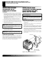
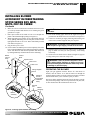
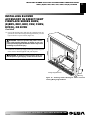
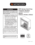
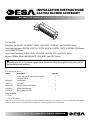
INSTALLATION INSTRUCTIONS
GA3750A BLOWER ACCESSORY
For more information, visit www.desatech.com
For Use With:
Fireboxes: (NL)FB32C, (NL)FB36C, FB42C, (NL)UV32C, CGFB32C, and CGFB36C Series
Vent-Free Fireplaces: VSGF28, VYGF33, VTGF33, VCGF30, VSGF33, FPV33, CGFP28, LFP33 Series,
and (CG)EFP33 Series
Direct-Vent Fireplaces: (E)BDV, BHDV, DVF(E)34, DVFH34, CDV, and CHDV Series
Stoves: CSDBN, SDVB, MSDVB MSTD, CDV, S39T, and S26T Series
WARNING: ELECTRICAL GROUNDING INSTRUCTIONS This appliance is equipped with a three-prong
(grounding) plug for your protection against shock hazard and should be plugged directly into a properly
grounded three-prong receptacle.
(Check your appliance owner’s manual for specific applications and additional instructions.)
Parts included with this kit:
Part No.
Description
Quantity
Blower with speed control and 6-foot cord.
1
Instruction Sheet
1
103650-01
Control Knob
1
103651-01
Lock Nut
1
M11084-38
#8 x 3/8" sheet metal screws
5
101629-01
Plastic Hole Bushings
2
101584-05
Wiring Diagram Decal
1
Tools Required
•
Pliers
•
Phillips Screwdriver
If any of these pieces are missing or damaged, or if the installation instructions for your fireplace or stove are not included in this manual,
contact the dealer where you purchased this kit or DESA at 1-866-672-6040 for referral information.
Save this manual for future reference.
2
INSTALLING BLOWER ACCESSORY IN A 32" FIREBOX
INSTALLING BLOWER
ACCESSORY IN A 32" FIREBOX
NOTICE: If a log set is currently installed in the firebox,
disconnect log set from gas supply and remove from
firebox. Contact a qualified service person to do this.
8.
Note: Appearance of firebox may vary slightly depending on
model.
1. Remove the firebox bottom:
a. Remove the 4 screws that secure the bottom of the firebox
(see Figure 1).
b. Carefully raise and remove the firebox bottom from the
firebox.
9.
WARNING: If there is a duplex electrical outlet
installed in the right side of the bottom of the fireplace
base area, be sure that the electrical power to the outlet
is turned off before proceeding with blower installation. Failure to do this may result in serious injury.
2.
3.
4.
5.
6.
7.
Attach the power cord to the blower motor by firmly pushing the two
female terminals at the end of the power cord onto the two spade
terminals on the blower motor.
Attach green ground wire from power cord to blower housing using screw provided (see Figure 2). Tighten screws securely.
Place the blower against lower rear wall of firebox wrapper
with the exhaust port directed upward. Align the holes in top
mounting tabs of blower with holes in wall of wrapper (see
Figure 2). Using 2 screws provided, mount blower and tighten
screws securely.
Be certain that all wire terminals are securely attached to terminals on blower motor and that the screw retaining the green
ground wire is tight.
Locate the plastic hole plug installed in the 3/8" diameter opening in the lower right side of the firebox front panel (see Figure 2). Remove the plastic plug and discard.
Place speed control against inner wall of front panel, pushing the
plastic control shaft forward through the opening (see Figure 3).
While supporting speed control, secure control shaft with lock
nut by pushing and turning lock nut with pliers clockwise until it is tight against front panel. Place control knob provided
on shaft (see Figure 3).
Plug in blower power cord.
a. If your firebox is installed as a freestanding unit, determine
whether the power cord will exit the left side or the right side
of the firebox. Install 1 plastic bushing provided into the 1 1/2"
hole in the floor support on the exit side. Install the second
plastic bushing provided into the 1 1/2" hole in the outer casing
through which the power cord will exit (see Figure 4). Route
power cord through both plastic bushings and plug the power
cord into a 3-prong grounded wall receptacle near the firebox.
b. If your firebox installation is recessed and/or pre-wired,
plug the power cord into the duplex outlet provided. Refer
to your firebox owner’s manual for instructions on wiring
the duplex outlet.
CAUTION: Never touch the blower wheel while in
operation.
Exhaust Port
Lower Rear Wall
of Firebox Wrapper
Top
Mounting
Tab
Screw
Screws
Floor
Supports
Blower
Plastic
Hole Plug
Figure 2 - Mounting Blower to Firebox
Note: Appearance of fireplace may vary by model.
Speed Control
Control Shaft
Lock
Nut
Screws
Plastic
Bushing
Control
Knob
Figure 1 - Removing Screws from Firebox Bottom
Figure 3 - Attaching Speed
Control
Figure 4 - Installing Plastic
Bushing for Power Cord
For more information, visit www.desatech.com
108319-01B
INSTALLING BLOWER ACCESSORY IN A 32" FIREBOX
INSTALLING BLOWER ACCESSORY IN 36" OR 42" FIREBOX
3
3
INSTALLING BLOWER
ACCESSORY IN A 32" FIREBOX
Continued
10. Turn on power to duplex outlet if previously turned off per the
warning in step 1, page 2.
11. Check to make sure that the power cord is completely clear of
the blower wheel and that there are no other foreign objects in
blower wheel. Turn blower on and check for operation.
12. Peel off the backing paper and stick the supplied wiring diagram decal on the firebox bottom approximately 12" in front
of the blower.
13. Replace bottom of firebox. Note: Make sure the back of the
firebox bottom slides under the rear of the firebrick (lift the
firebrick up if necessary.)
14. Reattach firebox bottom using 4 screws removed in step 1,
page 2. Note: Discard the remaining hardware items.
15. Install the log set heater according to the installation instructions supplied with the heater.
2.
d. Carefully lift and remove the concrete firebrick floor from
the firebox if installed (see Figure 5).
Remove the firebox bottom.
a. Remove the 4 screws that secure the bottom of the firebox
(see Figure 8).
b. Carefully raise and remove the firebox bottom from the firebox.
WARNING: If there is a duplex electrical outlet
installed in the right side of the bottom of the fireplace
base area, be sure that the electrical power to the outlet
is turned off before proceeding with the blower installation. Failure to do this may result in serious injury.
3.
Attach the power cord to the blower motor by firmly pushing
the two female terminals at the end of the power cord onto the
two spade terminals on the blower motor.
OPERATING THE BLOWER
Retainer Bracket
Screw
Light your gas appliance with the blower off. After about 15
minutes, turn the blower on to deliver heated air at the top louvers.
The blower features a variable control which allows you to select the
speed you desire.
Note: Periodically check the louvers of the firebox and remove any
dust, dirt or other obstructions.
INSTALLING BLOWER
ACCESSORY IN 36" OR 42"
FIREBOX
NOTICE: If a log set is installed in the firebox, disconnect log set from gas supply and remove from firebox.
Contact a qualified service person to do this.
Note: Appearance of firebox may vary depending on model.
1. If firebrick is installed, carefully lift and remove the concrete
firebrick floor from the firebox (see Figure 5). Some model
fireboxes require that you remove the side and rear panels first.
Follow the directions below to remove the side and rear firebrick panels for those fireboxes.
a. Using a Phillips screwdriver, remove the screw and retainer
bracket at the top of the brick liner panel on the left side. Carefully remove the left panel from the firebox (see Figure 6).
b. Repeat the removal steps for the brick liner panel on the
right side.
c. Remove the screw and retainer bracket at the top of the brick
liner panel at the rear of the firebox. IMPORTANT: Do not
let panel fall after bracket has bee removed. Carefully remove the rear panel from the firebox (see Figure 7).
Firebrick Floor
Left Panel
Figure 5 - Removing Firebrick Figure 6 - Removing Left Panel
from Firebox
Floor from Firebox
Screw
Retainer Bracket
Back
Panel
Figure 7 - Removing Back
Panel from Firebox
Screws
Figure 8 - Removing Firebox
Bottom
For more information, visit www.desatech.com
108319-01B
4
INSTALLING BLOWER ACCESSORY IN 36" OR 42" FIREBOX
INSTALLING BLOWER
ACCESSORY IN 36" OR 42"
FIREBOX
Continued
4.
5.
6.
7.
Attach green ground wire from power cord to blower housing
using screw provided (see Figure 9). Tighten screws securely.
Place the blower against the lower rear wall of the firebox outer
wrapper with the exhaust port directed upward. Align the holes
in top mounting tabs of blower with holes in wall of wrapper
(see Figure 9). Using 2 screws provided, mount blower and
tighten screws securely.
Be certain that all wire terminals are securely attached to terminals on blower motor and that the screw retaining the green
ground wire is tight.
Locate the plastic hole plug installed in the 3/8" diameter opening in the lower right side of the firebox front panel (see Figure 10). Remove the plastic plug and discard.
Exhaust Port
Top Mounting
Tab
Lower Rear Wall of
Firebox Wrapper
8.
Place speed control against inner wall of front panel, pushing
the plastic control shaft forward through the opening.
9. While supporting speed control, secure control shaft with lock
nut by pushing and turning lock nut with pliers clockwise until it is tight against front panel. Place control knob provided
on shaft (see Figure 11).
10. Turn on power to duplex outlet if previously turned off per the
warning in column 2, page 3.
11. Plug in blower power cord.
a. If your firebox is installed as a freestanding unit with an
accessory mantel, determine whether the power cord will
exit the left side or the right side of the firebox. Install 1 plastic bushing provided into the 1 1/2" hole in the floor support on
the exit side. Install the second plastic bushing provided into
the 1 1/2" hole in the outer casing through which the power
cord will exit (see Figures 10 and 12). Route power cord
through both plastic bushings and plug the power cord into a
wall receptacle near the firebox.
Speed Control
Control Shaft
Screw
Control Knob
Screws
Locknut
Figure 11 - Attaching Speed Control to Firebox
Blower
Figure 9 - Mounting Blower to Firebox
Floor
Supports
Plastic
Bushing
1 1/2" Hole
h c el b a
ti w i r a
Sn V
aF
r
rotewol
oM B
nO
ff O
kc
al
k
eti c al B
hW
kc
B
al
B
1 1/2" Hole
Plastic
Hole Plug
k
e c al
n e ti h W B
er G
5
. C 1 1/ 0
. A. 1 1
V
Wiring Diagram Decal 12"
in Front of Blower
Figure 10 - Installing Plastic Bushing for Power Cord
Figure 12 - Location of Wiring Diagram Decal
For more information, visit www.desatech.com
108319-01B
INSTALLING BLOWER ACCESSORY IN 36" OR 42" FIREBOX
INSTALLING BLOWER ACCESSORY IN MODEL SVFBC FREESTANDING STOVE
INSTALLING BLOWER
ACCESSORY IN MODEL SVFBC
FREESTANDING STOVE
Continued
CAUTION: Never touch the blower wheel while in
operation.
13. Peel off the backing paper and stick the supplied wiring diagram decal on the firebox bottom approximately 12" in front
of the blower (see Figure 12, page 4).
14. Replace and reattach firebox bottom using 4 screws removed
in step 2 (see Figure 8, page 3).
15. If previously removed, carefully replace the firebrick side panels and/or floor in the firebox (see Figures 5-7, page 3).
16. Install the log set heater according to the installation instructions supplied with the heater.
WARNING: A qualified service person must install
heater. Follow all local codes.
Note: Discard the remaining hardware items.
NOTICE: Shut off gas heater during the following blower
installation.
1.
2.
3.
4.
Remove the 2 screws and blower mounting bracket from the
rear bottom of the stove cabinet (see Figure 13).
Locate the plug button installed in the 10 mm diameter opening in the front of the lower right side panel of the stove cabinet (see Figure 14). Remove the plug button and discard.
Place speed control against inner wall of the pedestal, pushing
the plastic control shaft through the opening.
While supporting speed control, secure control shaft with lock
nut by pushing and turning lock nut with pliers clockwise until it is tight against side panel. Place control knob provided on
shaft (see Figure 15).
Screws
Blower
Mounting
Bracket
Variable
Fan Switch
Off
110/115
V.A.C.
On
Black
b. If your firebox installation is recessed and/or pre-wired,
plug the power cord into the duplex outlet provided. Refer
to your firebox owner’s manual for instructions on wiring
the duplex outlet.
12. Check to make sure that the power cord is completely clear of the
blower wheel and that there are no other foreign objects in blower
wheel. Turn blower on and check for operation. Turn blower off
by turning knob fully counter-clockwise before continuing.
Black
INSTALLING BLOWER
ACCESSORY IN 36" OR 42"
FIREBOX
5
5
Blower
Motor
Black
Black
White
Green
White
Wiring Diagram
Figure 13 - Location of Blower Mounting Bracket and Screws
;
;
;
;
;
;
;
;
;
;
;
;
;
;
;
;
;
;
;
;
;
;
;
;
;
;
;
;
;
;
;
;
;
;
;
;
;
;
;
;
;
;
;
;
;
;
;
;
;
;
;
;
;
;
;
;
;
;
;
;
;
;
;
;
;
;
;
;
;
;
;
;
;
;
;
;
;
;
;
;
;
;
;
;
;
;
;
;
;
;
;
;
;
;
;
;
;
;
;
;
;
;
;
;
;
;
;
;
;
;
;
;
;
;
;
;
;
;
;
;
;
;
;
;
;
;
;
;
;
;
;
;
;
;
;
;
;
;
;
;
;
;
;
;
;
;
;
;
;
;
;
;
;
;
;
;
;
;
;
;
;
;
;
;
;
;
;
;
;
;;;;;;;;;;;;;;;;;
;
Plug Button
OPERATING THE BLOWER
Light your gas appliance with the blower off. After about 15
minutes, turn the blower on to deliver heated air at the top louvers.
The blower features a variable control which allows you to select the
speed you desire.
Figure 14 - Location of Plug Button
Speed Control
Note: Periodically check the louvers of the firebox and remove any
dust, dirt, or other obstructions.
Control Shaft
Lock Nut
Control Knob
Figure 15 - Attaching Speed Control
For more information, visit www.desatech.com
108319-01B
6
INSTALLING BLOWER ACCESSORY IN MODEL SVFBC FREESTANDING STOVE
INSTALLING BLOWER ACCESSORY IN 32" FIREPLACE SYSTEMS
INSTALLING BLOWER
INSTALLING BLOWER
ACCESSORY IN MODEL SVFBC ACCESSORY IN 32"
FREESTANDING STOVE
FIREPLACE SYSTEMS
Continued
Attach the power cord to the blower motor by firmly pushing
the two female terminals at the end of the power cord onto the
two spade terminals on the blower motor.
6. Attach green ground wire from power cord to blower housing
using screw provided (see Figure 16). Tighten screws securely.
7. Place the blower on the mounting bracket with the exhaust
port directed upward. Align the holes in blower frame with
holes in bracket (see Figure 16). Using 4 screws provided mount
blower and tighten each screw.
8. Be certain that all wire terminals are securely attached to terminals on blower motor and that the screw retaining the green
ground wire is tight.
9. Reattach motor mounting bracket using screws removed in step
1, page 5.
10. Plug in power cord. This blower is supplied with a 3-prong,
grounding plug. It must be plugged into a standard 3-prong
grounded wall outlet near the stove.
11. Check to make sure that the power cord is completely clear of
the blower wheel and that there are no other foreign objects in
blower wheel. Turn blower on and check for operation. Turn
blower off by rotating knob fully counter-clockwise before
continuing.
NOTICE: Shut off gas supply and disconnect heater
from gas supply. Contact a qualified service person
to do this.
5.
Note: Appearance of firebox or burner system may vary depending
on model.
1. Remove fireplace screen per the instructions in operation
manual supplied with fireplace.
2. If logs are installed, carefully remove the logs and set aside,
noting the properly mounted location of each.
3. Remove screws that attach log base assembly to fireplace. Carefully lift up log base assembly and remove from fireplace, taking care to pull flexible gas line through the access holes (see
Figure 17).
CAUTION: Do not pick up log base assembly by
burners. This could damage burners. Only handle
base by grates.
4.
5.
Attach the power cord to the blower motor by firmly pushing the two
female terminals at the end of the power cord onto the two spade
terminals on the blower motor.
Attach green ground wire from power cord to blower housing using screw provided (see Figure 18). Tighten screws securely.
CAUTION: Never touch the blower wheel while in
operation.
12. Peel off the backing paper and stick the supplied wiring diagram decal on the back of the blower mounting bracket (see
Figure 13, page 5).
Note: Discard the remaining hardware items.
Screws
Exhaust Port
Blower
Flexible
Gas Line
Screws
Log Base
Figure 17 - Removing Log Base from Fireplace
Exhaust Port
Lower Rear
Wall of
Firebox
Top Mounting Tab
Mounting
Bracket
Ground
Wire
Figure 16 - Attaching Blower to Mounting Bracket
Screw
OPERATING THE BLOWER
Light your gas appliance with the blower off. After about 15 minutes, turn
the blower on to deliver heated air at the top louvers. The blower features
a variable control which allows you to select the speed you desire.
Green
Ground Wire
Screws
Blower
Figure 18 - Mounting Blower to Firebox
For more information, visit www.desatech.com
108319-01B
INSTALLING BLOWER ACCESSORY IN 32" FIREPLACE SYSTEMS
7
7
INSTALLING BLOWER
ACCESSORY IN 32"
FIREPLACE SYSTEMS
Continued
6.
Place the blower against lower rear wall of firebox outer wrapper with the exhaust port directed upward. Align the holes in
top mounting tabs of blower with holes in wall of wrapper
(see Figure 18, page 6). Using 2 screws provided, mount blower
and tighten screws securely.
7. Be certain that all wire terminals are securely attached to terminals on blower motor and that the screw retaining the green
ground wire is tight.
8. Place control knob provided on plastic control shaft of
speed control.
9. Mount the speed control on the front leg of the left floor support
bracket using 2 screws provided (see Figure 19). Note: Some
remote ready fireplace models have the gas control located near
the left floor support bracket. For these models, mount the blower
speed control onto the right floor support bracket.
10. Plug in blower power cord.
a. If your fireplace system is installed as a freestanding unit
with an accessory mantel, determine whether the power cord
will exit the left side or the right side of the firebox. Install 1
plastic bushing provided into the 1.5" hole in the floor support
bracket on the exit side (see Figure 20). Install the second plastic bushing provided into the 1.5" hole in the outer casing through
which the power cord will exit. Route power cord through both
plastic bushings and plug the power cord into a properly
grounded 3-prong wall receptacle near the firebox.
b. If your fireplace system installation is recessed and if an
outlet is not installed in your fireplace, you must install the
GA3555 Outlet kit with cover in your fireplace which will supply a convenient 3-prong grounded electrical outlet for your
blower. Refer to the installation manual provided with the model
GA3555 accessory for instructions on wiring the duplex outlet.
Note: A qualified installer must make all electrical connections.
11. Check to make sure that the power cord is completely clear of the
blower wheel and that there are no other foreign objects in blower
wheel. Turn blower on and check for operation. Turn blower off
by rotating knob fully counterclockwise before continuing.
CAUTION: Never touch the blower wheel while in
operation.
12. Peel off the backing paper and stick the supplied wiring diagram
decal on the firebox bottom approximately 3" to the right of the
blower speed control (Figure 21).
Right Floor
Support Bracket
Plastic
Bushing
Figure 20 - Installing Plastic Bushing for Power Cord
WARNING: Never attempt to service heater while it
is plugged in, operating, or hot. Burns and electrical
shock could result. Only a qualified service person
should service or repair heater.
kc
kc
B
W
al
ih
ff O
kc
B
et
al
al
B
1
01
1/ . V
5 1 C. A
.
B
al
kc h W
i
et er G
ne
Wiring
Diagram
Variable
Fan Switch
Screws
Green
White
Control
Shaft
On
Black
Black
Black
Off
110/115
V.A.C.
Control
Knob
nO
Speed Control
B
ol
w M
re oto
r
WARNING: Label all wires prior to disconnection
when servicing controls. Wiring errors can cause improper and dangerous operation. Verify proper operation after servicing.
V F
ir a n a
ba S
el ti w
hc
If any of the original wire as supplied with the appliance must be
replaced, it must be replaced with 105°C wire or it’s equivalent.
Left Floor
Support
Bracket
Black
Blower
Motor
White
120 Vac. 60 Hz. . 78 Amps
DESA, Bowling Green, KY
101584-05
Figure 19 - Attaching Speed Control to Firebox
Figure 21 - Location of Wiring Diagram Decal 3" from Blower
For more information, visit www.desatech.com
108319-01B
8
INSTALLING BLOWER ACCESSORY IN 32" FIREPLACE SYSTEMS
INSTALLING BLOWER ACCESSORY IN FREESTANDING STOVE SERIES
SDV, MSD, MSTD, CDV OR CSDBN
INSTALLING BLOWER
ACCESSORY IN 32"
FIREPLACE SYSTEMS
Continued
13. Replace log base assembly in fireplace. Feed flexible gas supply line into fireplace base area while replacing log base assembly. Make sure the entire flexible gas line is in fireplace
base area. Note: If firebrick is installed, make sure the back of
the firebox bottom slides under the rear panel of the firebrick
(lift the firebrick up if necessary).
IMPORTANT: Do not pick up log base assembly by burners.
This could damage burners. Only handle base by grates.
14. Reattach log base assembly to fireplace with screws removed
in step 3, page 5. Note: Discard the remaining hardware items.
15. Install logs and fireplace screen per instructions in operating
manual provided with fireplace.
INSTALLING BLOWER
ACCESSORY IN FREESTANDING
STOVE SERIES SDV, MSD,
MSTD, CDV OR CSDBN
IMPORTANT: Read all installation instructions before installing blower.
NOTICE: Shut off gas supply and disconnect heater
from gas supply. Contact a qualified service person
to do this.
INSTALLING THE BLOWER
1.
2.
WARNING: Failure to position the parts in accordance with supplied diagrams or failure to use only
parts specifically approved with this heater may result
in damage or personal injury.
3.
4.
16. Connect gas supply to fireplace per instructions in operating
manual provided with fireplace.
5.
WARNING: A qualified service person must connect fireplace to gas supply. Follow all local codes.
OPERATING THE BLOWER
Remove 4 hex bolts securing rear cover to back of stove body
(see Figure 22).
Separate bottom cover from rear cover by loosening the 8
mounting screws (see Figure 22).
Align the holes in the top mounting tabs of blower with the
holes in wall of rear cover (see Figure 23, page 9). Using the 4
screws provided, mount blower and tighten screws securely.
Attach the power cord to the blower motor by firmly pushing
the two female terminals at the end of the power cord onto the
two spade terminals on the blower motor.
Attach green ground wire from power cord to blower housing using screw provided (see Figure 23, page 9). Tighten
screw securely.
Rear Cover
Light your gas appliance with the blower off. After about 15
minutes, turn the blower on to deliver heated air at the top louvers.
The blower features a variable control which allows you to select the
speed you desire. Note: Periodically check the louvers of the firebox and remove any dust, dirt, or other obstructions.
Screw
(Note: Stove Body
May Vary by Model)
Figure 22 - Removing/ Installing Rear Cover
For more information, visit www.desatech.com
108319-01B
INSTALLING BLOWER ACCESSORY IN FREESTANDING STOVE SERIES
SDV, MSD, MSTD, CDV OR CSDBN
9
9
INSTALLING BLOWER
ACCESSORY IN FREESTANDING
STOVE SERIES SDV, MSD,
MSTD, CDV OR CSDBN
Continued
6.
Make sure all wire connections to terminals on blower motor
are securely attached and that the screw retaining the green
ground wire is tight.
7. Place speed control on left inside of rear cover and push the
plastic control shaft through opening (see Figure 23).
8. While supporting speed control, secure control shaft with lock
nut by pushing and turning lock nut with pliers clockwise until
tight against the side of rear cover. Place control knob provided
onto shaft (see Figure 23).
9. Plug in blower power cord.
10. Check to make sure that the power cord is completely clear of the
blower wheel and that there are no other foreign objects in blower
wheel. Turn blower on and check for operation. Turn blower off
by rotating knob fully counterclockwise before continuing.
Blower
Control
Knob
Control
Shaft
Speed Control
Rear Cover
Power Cord
Lock Nut
Wiring Diagram
Decal
Mounting
Screws
(Included in
Hardware
Pack)
Exhaust
Port
CAUTION: Never touch the blower wheel while in
operation.
13. Peel off the backing paper and stick the supplied wiring diagram decal on the inside of rear cover as shown (see Figure 23).
14. Connect or reconnect gas supply following instructions given
in the owner’s manual supplied with your fireplace.
WARNING: A qualified service person must connect fireplace to gas supply. Follow all local codes.
15. Reattach bottom cover to rear cover with 8 screws (see Figure 22,
page 8). Make sure that you don’t pinch any wires during
reassembly.
16. Secure rear cover to back of stove chassis (see Figure 22, page 8).
17. Plug in the power cord when ready to use.
WARNING: Failure to position the parts in accordance with supplied diagrams or failure to use only
parts specifically approved with this heater may result
in damage or personal injury.
OPERATING THE BLOWER
Light your gas appliance with the blower off. After about 15
minutes, turn the blower on to deliver heated air through the
openings in the top of the stove body. The blower features a variable
control which allows you to select the speed you desire.
The blower helps distribute heated air from the fireplace. Periodically check the openings of the stove top and remove any dust, dirt,
or other obstructions that will hinder the flow of air.
Blower
Assembly
Blower
Assembly
Screw
Green Ground
Wire
Figure 23 - Installing Optional Blower Accessory
For more information, visit www.desatech.com
108319-01B
10
INSTALLING BLOWER ACCESSORY IN DIRECT-VENT FIREPLACE SERIES
BHDV, (E)BDV, DDV, HDV, CDV, CHDV, DVF(E), OR DVFH
INSTALLING BLOWER
ACCESSORY IN DIRECT-VENT
FIREPLACE SERIES BHDV,
(E)BDV, DDV, HDV, CDV, CHDV,
DVF(E), OR DVFH
IMPORTANT: Read all installation instructions before installing blower.
NOTICE: Shut off gas supply and disconnect heater
from gas supply. Contact a qualified service person
to do this.
IMPORTANT: For clarity, gas valve assembly and grate/burner
assembly are not shown in Figures 24 and 25. They will, however,
be in your fireplace when you are installing the blower. Also for
clarity the firebox is shown with dotted lines.
1. Open lower louver panel as shown in Figure 24.
2. Attach the power cord to the blower motor by firmly pushing
the two female terminals at the end of the power cord onto the
two spade terminals on the blower motor.
3. Attach green ground wire from power cord to blower housing
using screw provided (see Figure 24). Tighten screw securely.
4. Place the blower under the firebox and against the lower rear
wall of firebox outer wrapper with the exhaust port directed
upward. Align the holes in the top mounting tabs of blower
with holes in wall of wrapper (see Figure 24). Using the two
screws provided, mount blower and tighten screws securely.
5. Be sure all wire terminals on blower are attached securely.
Make sure the screw retaining the green wire is tight.
6. Remove screws securing the plate containing the ON/OFF
switch to the bottom of the firebox and set aside.
7. Place speed control against the back of this plate and push the
plastic control shaft through opening (see Figure 25).
8. While supporting speed control, secure control shaft with lock
nut by pushing and turning lock nut with pliers clockwise until tight against the plate. Place control knob (provided) onto
shaft (see Figure 25).
9. Replace plate containing switches and tighten screws securely.
10. Plug in blower power cord.
a. If your fireplace system is installed as a freestanding unit
with an accessory mantel, determine whether the power cord
will exit the left side or the right side of the firebox. Install
one plastic bushing (provided) into the 1 1/2" hole in the outer
casing through which the power cord will exit. Install the second plastic bushing (provided) into the floor support bracket
if exiting through the right side (see Figure 26, page 11). Route
power cord through (both) plastic bushing(s) and plug the
power cord into a properly grounded 3-prong wall receptacle
near the firebox.
b. If your fireplace system installation is recessed and/or
pre-wired, a qualified installer must make all electrical connections for the outlet kit included with the fireplace.
11. Check to make sure that the power cord is completely clear of the
blower wheel and that there are no other foreign objects in blower
wheel. Turn blower on and check for operation. Turn blower off
by rotating knob fully counterclockwise before continuing.
CAUTION: Never touch the blower wheel while in
operation.
Lower Rear
Wall of
Firebox
Wrapper
Exhaust Port
Screw
Green
Ground Wire
Blower Assembly
Screws
Lower Louver
Panel
Figure 24 - Mounting Blower to Firebox
Speed Control
Control Shaft
Locknut
Control
Knob
Switch
Plate
Figure 25 - Attaching Speed Control to Firebox
For more information, visit www.desatech.com
108319-01B
INSTALLING BLOWER ACCESSORY IN DIRECT-VENT FIREPLACE SERIES
BHDV, (E)BDV, DDV, HDV, CDV, CHDV, DVF(E), OR DVFH
11
11
INSTALLING BLOWER
ACCESSORY IN DIRECT-VENT
FIREPLACE SERIES BHDV,
(E)BDV, DDV, HDV, CDV, CHDV,
DVF(E), OR DVFH
Continued
12. Peel off the backing paper and stick the supplied wiring diagram decal on the outer casing bottom approximately 3" to the
right of the blower speed control (Figure 26).
WARNING: Failure to position the parts in accordance with supplied diagrams or failure to use only
parts specifically approved with this heater may result
in damage or personal injury.
13. Connect or reconnect gas supply following instructions given
in the owner's manual supplied with your fireplace.
WARNING: A qualified service person must connect fireplace to gas supply. Follow all local codes.
Wiring Diagram Decal
Plastic
Bushing
Figure 26 - Installing Plastic Bushing for Power Cord and
Locating Wiring Diagram Decal
For more information, visit www.desatech.com
108319-01B
12
2701 Industrial Drive, P.O. Box 90004
Bowling Green, KY 42102-9004
Technical Service Department 1-866-672-6040
www.desatech.com
108319 01
NOT A UPC
108319-01
REV. B
09/03
For more information, visit www.desatech.com
108319-01B