1
RACK
INSTALLATION
GUIDE
www.dell.com
support.dell.com
RACK INSTALLATION GUIDE
www.dell.com
support.dell.com
Information in this document is subject to change without notice.
© 2000 Dell Computer Corporation. All rights reserved.
Reproduction in any manner whatsoever without the written permission of Dell Computer Corporation is strictly forbidden.
Trademarks used in this text: Dell, the DELL E COM logo, RapidRails, and PowerVault are trademarks of Dell Computer Corporation.
Other trademarks and trade names may be used in this document to refer to either the entities claiming the marks and names or their
products. Dell Computer Corporation disclaims any proprietary interest in trademarks and trade names other than its own.
July 2000
P/N 15RYH Rev. A01
!!"#$
Safety Instructions
Use the following safety guidelines to ensure your own personal safety and to help
protect your server, storage system, or appliance from potential damage.
Notes, Notices, Cautions, and Warnings
Throughout this guide, blocks of text may be accompanied by an icon and printed in
bold type or in italic type. These blocks are notes, notices, cautions, and warnings,
and they are used as follows:
NOTE: A NOTE indicates important information that helps you make better use of your
computer system.
NOTICE: A NOTICE indicates either potential damage to hardware or loss
of data and tells you how to avoid the problem.
CAUTION: A CAUTION indicates a potentially hazardous situation which, if
not avoided, may result in minor or moderate injury.
WARNING: A WARNING indicates a potentially hazardous situation which,
if not avoided, could result in death or serious bodily injury.
Safety Caution and Warnings
Observe the following caution and warnings while servicing this system:
CAUTION: There is a danger of a new battery exploding if it is incorrectly
installed. Replace the battery only with the same or equivalent type recommended by the manufacturer. Discard used batteries according to the
manufacturer’s instructions.
WARNING: This system may have more than one power supply cable. To
reduce the risk of electrical shock, a trained service technician must disconnect all power supply cables before servicing the system.
!"#$% &'()
*+,+% -* ,.'%*+%/!*.0#.1 &2%'/*+$+%
!30!*"04*+..0!#+'2$ !"#% &'(
iii
!!"#$
ADVARSEL: Dette system kan have mere end et strømforsyningskabel. For
at reducere risikoen for elektrisk stød, bør en professionel servicetekniker
frakoble alle strømforsyningskabler, før systemet serviceres.
VAROITUS: Tässä järjestelmässä voi olla useampi kuin yksi virtajohto. Sähköiskuvaaran pienentämiseksi ammattitaitoisen huoltohenkilön on
irrotettava kaikki virtajohdot ennen järjestelmän huoltamista.
!
"#
$%&$'
(
#
) $
#*
"
"$)
'
5657+89+:#+7#0% &', +' + (;&
,+#,8*,%!* 7+ !*<01!*,0 !* 9<'.&%*9 #<.
9,%+% &', +' + !9+&80=<,!*,,!*,,%'>$+% &=.>+(
ADVARSEL! Det er mulig at dette systemet har mer enn én strømledning.
Unngå fare for støt: En erfaren servicetekniker må koble fra alle strømledninger før det utføres service på systemet.
VARNING: Detta system kan ha flera nätkablar. En behörig servicetekniker
måste koppla loss alla nätkablar innan service utförs för att minska risken
för elektriska stötar.
Additional Safety Precautions
To reduce the risk of bodily injury, electrical shock, fire, and damage to the equipment,
observe the following precautions.
General Precautions
Observe the following general precautions for using and working with your system:
•
Observe and follow service markings. Do not service any Dell product except as
explained in your Dell system documentation. Opening or removing covers that
are marked with the triangular symbol with a lightning bolt may expose you to
electrical shock. Components inside these compartments should be serviced
only by a Dell authorized service technician.
•
If any of the following conditions occur, unplug the product from the electrical
outlet and replace the part or contact your Dell authorized service provider:
—
The power cable, extension cable, or plug is damaged.
—
An object has fallen into the product.
—
The product has been exposed to water.
—
The product has been dropped or damaged.
iv
!!"#$
—
The product does not operate correctly when you follow the operating
instructions.
•
Keep your system components away from radiators and heat sources. Also, do
not block cooling vents.
•
Do not spill food or liquids on your system components, and never operate the
product in a wet environment. If the computer gets wet, see the appropriate
chapter in your troubleshooting guide or contact a Dell-authorized service
provider.
•
Do not push any objects into the openings of your system components. Doing so
can cause fire or electric shock by shorting out interior components.
•
•
Use the product only with Dell products or other Dell-approved equipment.
•
Use the correct external power source. Operate the product only from the type
of power source indicated on the electrical ratings label. If you are not sure of the
type of power source required, consult your Dell service provider or local power
company.
•
To help avoid damaging your system components, be sure the voltage selection
switch (if provided) on the power supply is set to match the power available at
your location:
Allow the product to cool before removing covers or touching internal
components.
—
115 volts (V)/60 hertz (Hz) in most of North and South America and some Far
Eastern countries such as South Korea and Taiwan
—
100 V/50 Hz in eastern Japan and 100 V/60 Hz in western Japan
—
230 V/50 Hz in most of Europe, the Middle East, and the Far East
Also be sure that your monitor and attached devices are electrically rated to operate with the power available in your location.
•
Use only approved power cable(s). If you have not been provided with a power
cable for your server, storage system, or appliance, or for any AC-powered option
intended for your system, purchase a power cable that is approved for use in your
country. The power cable must be rated for the product and for the voltage and
current marked on the product’s electrical ratings label. The voltage and current
rating of the cable should be greater than the ratings marked on the product.
•
To help prevent electric shock, plug the system/components and peripheral
power cables into properly grounded electrical outlets. These cables are
equipped with three-prong plugs to help ensure proper grounding. Do not use
adapter plugs or remove the grounding prong from a cable. If you must use an
extension cable, use a three-wire cable with properly grounded plugs.
•
Observe extension cable and power strip ratings. Make sure that the total
ampere rating of all products plugged into the extension cable or power strip
does not exceed 80 percent of the extension cable or power strip ampere ratings
limit.
v
!!"#$
•
To help protect your system/components from sudden, transient increases and
decreases in electrical power, use a surge suppressor, line conditioner, or uninterruptible power supply (UPS).
•
Position system cables and power cables carefully; route system cables and the
power cable and plug so that they cannot be stepped on or tripped over. Be sure
that nothing rests on your system components’ cables or power cable.
•
Do not modify power cables or plugs. Consult a licensed electrician or your
power company for site modifications. Always follow your local/national wiring
rules.
•
To help avoid possible damage to the system board, wait 5 seconds after turning
off the system before removing a component from the system board or disconnecting a peripheral device from the computer.
•
Handle batteries carefully. Do not disassemble, crush, puncture, short external
contacts, dispose of in fire or water, or expose batteries to temperatures higher
than 60 degrees Celsius (140 degrees Fahrenheit). Do not attempt to open or service batteries; replace batteries only with batteries designated for the product.
•
Turn down the volume before using headphones or other audio devices.
Precautions for Servers, Storage Systems, and Appliances
Observe the following additional safety guidelines for your system:
•
Unless your installation and/or troubleshooting documentation specifically allows
it, do not remove enclosure covers, attempt to override the safety interlocks, or
access any components inside the system. Depending on your system, installation and repairs may be done only by individuals who are qualified to service your
computer or storage system equipment and trained to deal with products capable of producing hazardous energy levels.
•
When connecting or disconnecting power to hot-pluggable power supplies, if
offered with your Dell product, observe the following guidelines:
•
—
Install the power supply before connecting the power cable to the power
supply.
—
Unplug the power cable before removing the power supply.
—
If the system has multiple sources of power, disconnect power from the system by unplugging all power cables from the power supplies.
Move products with care; ensure that all casters and/or stabilizers are firmly connected to the computer or storage system. Avoid sudden stops and uneven
surfaces.
Precautions for Rack-Mountable Products
Observe the following precautions for rack stability and safety. Also refer to the rack
installation documentation accompanying the system and the rack for specific warning and/or caution statements and procedures.
vi
!!"#$
Servers, storage systems, and appliances are considered to be components in a rack.
Thus, “component” refers to any server, storage system, or appliance, as well as to
various peripherals or supporting hardware.
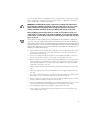
WARNING: Installing Dell system components in a Dell rack without the
front and side stabilizers installed could cause the rack to tip over, potentially resulting in bodily injury under certain circumstances. Therefore,
always install the stabilizers before installing components in the rack.
After installing system/components in a rack, never pull more than one
component out of the rack on its slide assemblies at one time. The weight
of more than one extended component could cause the rack to tip over and
injure someone.
NOTE: Dell’s servers, storage systems, and appliances are certified as components
for use in Dell’s rack cabinet using the Dell customer rack kit. The final installation of
Dell systems and rack kits in any other brand of rack cabinet has not been approved by
any safety agencies. It is the customer’s responsibility to have the final combination of
Dell systems and rack kits for use in other brands of rack cabinets evaluated for suitability by a certified safety agency.
•
System rack kits are intended to be installed in a Dell rack by trained service technicians. If you install the kit in any other rack, be sure that the rack meets the
specifications of a Dell rack.
•
Do not move large racks by yourself. Due to the height and weight of the rack,
Dell recommends a minimum of two people to accomplish this task.
•
Before working on the rack, make sure that the stabilizers are secure to the rack,
extend to the floor, and that the full weight of the rack rests on the floor. Install
front and side stabilizers on a single rack or front stabilizers for joined multiple
racks before working on the rack.
•
Always load the rack from the bottom up, and load the heaviest item in the rack
first.
•
Make sure that the rack is level and stable before extending a component from
the rack.
•
Use caution when pressing the component rail release latches and sliding a component into or out of a rack; the slide rails can pinch your fingers.
•
After a component is inserted into the rack, carefully extend the rail into a locking
position, and then slide the component into the rack.
•
Do not overload the AC supply branch circuit that provides power to the rack. The
total rack load should not exceed 80 percent of the branch circuit rating.
•
•
Ensure that proper airflow is provided to components in the rack.
Do not step on or stand on any system/component when servicing other systems/components in a rack.
vii
!!"#$
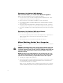
Precautions for Products With Modems,
Telecommunications, or Local Area Network Options
Observe the following guidelines when working with options:
•
Do not connect or use a modem or telephone during a lightning storm. There
may be a risk of electrical shock from lightning.
•
•
Never connect or use a modem or telephone in a wet environment.
•
Disconnect the modem cable before opening a product enclosure, touching or
installing internal components, or touching an uninsulated modem cable or jack.
•
Do not use a telephone line to report a gas leak while you are in the vicinity of the
leak.
Do not plug a modem or telephone cable into the network interface controller
(NIC) receptacle.
Precautions for Products With Laser Devices
Observe the following precautions for laser devices:
•
Do not open any panels, operate controls, make adjustments, or perform procedures on a laser device other than those specified in the product’s
documentation.
•
Only authorized service technicians should repair laser devices.
When Working Inside Your Computer
Before you remove the computer covers, perform the following steps in the sequence
indicated.
CAUTION: Some Dell systems can be serviced only by trained service technicians because of high voltages and energy hazards. Do not attempt to
service the computer system yourself, except as explained in this guide and
elsewhere in Dell documentation. Always follow installation and service
instructions closely.
NOTICE: To help avoid possible damage to the system board, wait 5 seconds after turning off the system before removing a component from the
system board or disconnecting a peripheral device from the computer.
1.
Turn off your computer and any devices.
2.
Ground yourself by touching an unpainted metal surface on the chassis, such as
the metal around the card-slot openings at the back of the computer, before
touching anything inside your computer.
While you work, periodically touch an unpainted metal surface on the computer
chassis to dissipate any static electricity that might harm internal components.
viii
!!"#$
3.
Disconnect your computer and devices from their power sources. Also, disconnect any telephone or telecommunication lines from the computer.
Doing so reduces the potential for personal injury or shock.
In addition, take note of these safety guidelines when appropriate:
•
When you disconnect a cable, pull on its connector or on its strain-relief loop, not
on the cable itself. Some cables have a connector with locking tabs; if you are disconnecting this type of cable, press in on the locking tabs before disconnecting
the cable. As you pull connectors apart, keep them evenly aligned to avoid bending any connector pins. Also, before you connect a cable, make sure that both
connectors are correctly oriented and aligned.
•
Handle components and cards with care. Don’t touch the components or contacts on a card. Hold a card by its edges or by its metal mounting bracket. Hold a
component such as a microprocessor chip by its edges, not by its pins.
CAUTION: There is a danger of a new battery exploding if it is incorrectly
installed. Replace the battery only with the same or equivalent type recommended by the manufacturer. Discard used batteries according to the
manufacturer’s instructions.
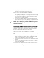
Protecting Against Electrostatic Discharge
Static electricity can harm delicate components inside your computer. To prevent
static damage, discharge static electricity from your body before you touch any of
your computer’s electronic components, such as the microprocessor. You can do so
by touching an unpainted metal surface on the computer chassis.
As you continue to work inside the computer, periodically touch an unpainted metal
surface to remove any static charge your body may have accumulated.
You can also take the following steps to prevent damage from electrostatic discharge
(ESD):
•
When unpacking a static-sensitive component from its shipping carton, do not
remove the component from the antistatic packing material until you are ready to
install the component in your computer. Just before unwrapping the antistatic
packaging, be sure to discharge static electricity from your body.
•
When transporting a sensitive component, first place it in an antistatic container
or packaging.
•
Handle all sensitive components in a static-safe area. If possible, use antistatic
floor pads and workbench pads.
The following notice may appear throughout this document to remind you of these
precautions:
NOTICE: See “Protecting Against Electrostatic Discharge” in the safety
instructions at the front of this guide.
ix
!!"#$
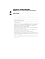
Ergonomic Computing Habits
CAUTION: Improper or prolonged keyboard use may result in injury.
CAUTION: Viewing the monitor screen for extended periods of time may
result in eye strain.
For comfort and efficiency, observe the following ergonomic guidelines when you set
up and use your computer system:
•
Position your system so that the monitor and keyboard are directly in front of you
as you work. Special shelves are available (from Dell and other sources) to help
you correctly position your keyboard.
•
Set the monitor at a comfortable viewing distance (usually 510 to 610 millimeters
[20 to 24 inches] from your eyes).
•
Make sure that the monitor screen is at eye level or slightly lower when you sit in
front of the monitor.
•
Adjust the tilt of the monitor, its contrast and brightness settings, and the lighting
around you (such as overhead lights, desk lamps, and the curtains or blinds on
nearby windows) to minimize reflections and glare on the monitor screen.
•
•
Use a chair that provides good lower back support.
•
•
•
•
Always leave space to rest your hands while you use the keyboard or mouse.
•
Vary your work activities. Try to organize your work so that you do not have to
type for extended periods of time. When you stop typing, try to do things that
use both hands.
Keep your forearms horizontal with your wrists in a neutral, comfortable position
while you use the keyboard or mouse.
Let your upper arms hang naturally at your sides.
Sit erect, with your feet resting on the floor and your thighs level.
When sitting, make sure the weight of your legs is on your feet and not on the
front of your chair seat. Adjust your chair’s height or use a footrest, if necessary,
to maintain proper posture.
x
!!"#$
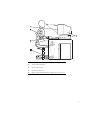
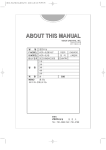
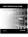
1
Monitor screen at or below eye level
2
Wrists relaxed and flat
3
Arms at desk level
4
Feet flat on the floor
5
Monitor and keyboard positioned directly in front of user
xi
!!"#$
xii
Contents
Rack Kit Contents . . . . . . . . . . . . . . . . . . . . . . . . . . . . . . . . . . . . . . . . . . . . . . . . . . 1-1
Other Documents You May Need . . . . . . . . . . . . . . . . . . . . . . . . . . . . . . . . . . . . . . 1-1
Before You Begin . . . . . . . . . . . . . . . . . . . . . . . . . . . . . . . . . . . . . . . . . . . . . . . . . . 1-2
Recommended Tools and Supplies . . . . . . . . . . . . . . . . . . . . . . . . . . . . . . . . . . . . . 1-2
Installing the Rack Kit . . . . . . . . . . . . . . . . . . . . . . . . . . . . . . . . . . . . . . . . . . . . . . . 1-3
Removing the Doors From the Rack . . . . . . . . . . . . . . . . . . . . . . . . . . . . . . . . 1-3
Removing the Doors From the Dell 42-U Rack . . . . . . . . . . . . . . . . . . . . . 1-3
Removing the Doors From the Dell 24-U Rack . . . . . . . . . . . . . . . . . . . . . 1-5
Installing the Rail Slide Assemblies in the Rack . . . . . . . . . . . . . . . . . . . . . . . . 1-6
Installing the Storage System in the Rack . . . . . . . . . . . . . . . . . . . . . . . . . . . 1-10
Replacing the Rack Doors . . . . . . . . . . . . . . . . . . . . . . . . . . . . . . . . . . . . . . . 1-11
Replacing the Rack Doors on a 42-U Rack . . . . . . . . . . . . . . . . . . . . . . . 1-11
Replacing the Rack Doors on a 24-U Rack . . . . . . . . . . . . . . . . . . . . . . . 1-11
xiii
xiv
!!%"#$
Dell™ PowerVault™ 660F and
224F Storage Systems Rack
Installation Guide
This installation guide provides instructions for trained service technicians installing
one or more Dell PowerVault 660F or 224F storage systems in a Dell rack. One rack kit
is required for each PowerVault system to be installed in the rack.
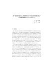
Rack Kit Contents
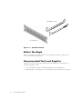
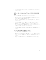
The rack kit includes the following items (see Figure 1-1):
•
One pair of RapidRails™
NOTE: If you purchased a Dell rack along with your storage system, the slide
assemblies may be preinstalled in the rack.
•
One 3-U template for a four-post Dell rack
Other Documents You May Need
Besides this Rack Installation Guide, the following documentation may be required for
installing your system in the rack:
•
Dell PowerVault 660F and 224F Storage Systems Installation and Troubleshooting
Guide
support.dell.com
Rack Installation Guide
1-1
!!%"#$
RapidRails™ (1 pair)
3-U template (1)
Figure 1-1. Rack Kit Contents
Before You Begin
Before you install your storage system in the rack, please read the “Safety Instructions” found earlier in this guide.
Recommended Tools and Supplies
Although no tools are required to install the slide assemblies, the following items
make the installation easier:
•
•
The 3-U template, helpful in slide assembly placement and alignment
Masking tape or a felt-tip pen, for use in marking the mounting holes to be used
1-2
Rack Installation Guide
!!%"#$
Installing the Rack Kit
NOTE: For instructions on installing your PowerVault storage system, see “Installing
the Storage System in the Rack” found later in this guide.
The following subsections include instructions for performing the following tasks for
PowerVault storage systems:
•
•
•
•
Removing the doors from the rack
Installing the slide assemblies in the rack
Installing the storage system in the rack
Replacing the rack’s front and back doors
Removing the Doors From the Rack
You must remove the doors from the rack to provide access to the interior of the rack
and to prevent damage to the doors while installing the storage system.
Removing the Doors From the Dell 42-U Rack
CAUTION: To prevent personal injury due to the size and weight of the
doors, never attempt to remove the doors by yourself.
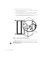
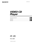
1.
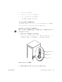
Open the latch on the front door (see Figure 1-2).
Slide the button cover up as far as it can go, press the push button, rotate the
handle clockwise until the latch releases, and then pull the door open.
push-button
cover
push button
handle
Figure 1-2. Opening the 42-U Rack Door
support.dell.com
Rack Installation Guide
1-3
!!%"#$
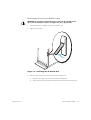
2.
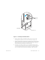
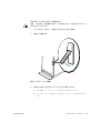
Remove the front door from the rack as shown in Figure 1-3.
a.
One person should grasp the top of the door to stabilize it. The other person
should grasp the bottom of the door.
b.
The person holding the bottom of the door should press the hinge release
lever on the bottom hinge and then pull the door away from the rack.
c.
The person holding the top of the door should press the hinge release lever
on the top hinge and then pull the door away from the rack.
hinge
release
lever
Figure 1-3. Removing the 42-U Rack Doors
3.
Repeat steps 1 and 2 to remove the back door from the rack, but turn the door
handle counter-clockwise.
CAUTION: Store the two doors where they cannot injure someone if the
doors accidently fall over.
1-4
Rack Installation Guide
!!%"#$
Removing the Doors From the Dell 24-U Rack
CAUTION: To prevent personal injury due to the size and weight of the
doors, never attempt to remove or replace the doors by yourself.
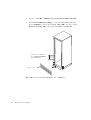
1.
Unlock and twist the handle clockwise (see Figure 1-4).
2.
Open the front door.
Figure 1-4. Unlocking the 24-U Rack Door
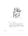
3.
Remove the front door from the rack as shown in Figure 1-5.
a.
With the door open, lift out and fully retract all hinge pins.
b.
Once all the hinge pins have been lifted out and retracted, lift the door out.
support.dell.com
Rack Installation Guide
1-5
!!%"#$
hinge pin
hinge insert
hinge
Figure 1-5. Removing the 24-U Rack Doors
CAUTION: Store the two doors where they will not injure someone if the
doors accidently fall over.
If you want to reverse the door so that the handle is on the other side, perform the following steps:
1.
With the door open, lift out and fully retract all hinge pins.
2.
Remove the hinges and door brackets from the door frame.
3.
Replace the hinges and door brackets on the opposite side and switch the position of the handle.
4.
Replace the rack door (see the section, “Replacing the Rack Doors,” found later
in this guide).
Installing the Rail Slide Assemblies in the Rack
NOTE: If the slide assemblies were preinstalled by Dell, you can skip to the section,
“Installing the Storage System in the Rack,” found later in this guide.
Use the 3-U rack template to determine where you want to install the slide assemblies. The rack template is the same height as the system chassis.
1-6
Rack Installation Guide
!!%"#$
You must allow 3U (5.25 inches) of vertical space for each system you install in the
rack.
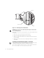
NOTE: The vertical rails of the rack are marked by small indentations in 1-U increments
(see Figure 1-6).
1 U (1.75 inches)
Figure 1-6. One-Rack Unit
For more information about requirements for installing components in a Dell rack, see
the Dell Rack Advisor software available on the Dell World Wide Web site at:
http://support.dell.com.
WARNING: If you are installing more than one system, install the slide
assemblies so that the first system is installed in the lowest available position in the rack.
To determine where to install the slide assemblies in the rack, perform the following
steps:
1.
Place the front of the template on the vertical rails at the front of the rack where
you want to install the system.
The printing on the template identifies the side facing outwards as the template
front.
2.
Position the bottom of the template where the system’s lower edge will be
located.
support.dell.com
Rack Installation Guide
1-7
!!%"#$
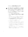
3.
Mark the rack’s front vertical rails with a felt-tip marker or place masking tape
where the system’s upper and lower edges will be located (see Figure 1-7). Make
a mark or place tape on the vertical rails next to the template’s V-shaped notches.
3 U (5.25 inches) between
slide assemblies
(drawing is not to scale)
rack template
Figure 1-7. Using the Template to Mark the Vertical Rails
1-8
Rack Installation Guide
!!%"#$
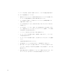
mounting
hooks (2)
front of rack
RapidRails™ (2)
Figure 1-8. Installing the Slide Assemblies
4.
Align the slide-assembly mounting-bracket flange (on the front of the slide
assembly) with the square holes in the front vertical rails (see Figure 1-8).
5.
Push the slide assembly forward until the mounting hooks are located in their
respective square holes on the vertical rail, and then push down on the mountingbracket flange until the mounting hooks engage the square holes in the front
vertical rail, allowing the push button to pop out and click.
6.
At the back of the cabinet, pull back on the mounting-bracket flange until the
mounting hooks are located in their respective square holes, and then push down
on the mounting-bracket flange until the mounting hooks engage the square
holes on the back vertical rail, allowing the push button to pop out and click.
support.dell.com
Rack Installation Guide
1-9
!!%"#$
7.
Repeat steps 3 through 7 for the remaining slide assembly on the other side of
the rack.
Installing the Storage System in the Rack
WARNING: If you are installing more than one PowerVault system, install
the heaviest system in the lowest available position in the rack.
WARNING: Never pull more than one component out of the rack at a time.
1.
Lift the storage system into position.
CAUTION: Because of the size and weight of the system, never attempt to
install the system in the slide assemblies by yourself.
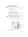
2.
Tilt the rear of the storage system upward and position the flange on the rail
assemblies inside the mounting channels on both sides of the system.
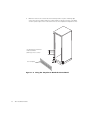
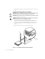
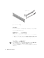
3.
Tilt the front of the storage system upward and push the system into the rack
until the mounting plate on the system rests against the vertical rails (see
Figure 1-9).
4.
Tighten the captive thumbscrews to each rack adapter bracket.
mounting
hooks (2)
Figure 1-9. Installing the Storage System in the Rack
1-10
Rack Installation Guide
!!%"#$
Replacing the Rack Doors
The following subsections describe procedures for replacing the rack doors on the
42-U rack and the 24-U rack.
Replacing the Rack Doors on a 42-U Rack
CAUTION: To prevent personal injury due to the size and weight of the
doors, never attempt to remove or replace the doors by yourself.
1.
Lift the front door into position and align the hinges with the holes in the rack as
shown in Figure 1-3.
2.
Slide the hinges into the holes in the rack until the hinge release levers lock the
hinges into position.
3.
Close the door latch by rotating the handle counterclockwise until it stops, push
in the handle until it locks in position, and then slide the button cover down over
the push button.
4.
Repeat steps 1 through 3 to install the back door, but turn the handle clockwise.
Replacing the Rack Doors on a 24-U Rack
CAUTION: To prevent personal injury due to the size and weight of the
doors, never attempt to remove or replace the doors by yourself.
1.
Lift the front door into position and align the hinges with the holes in the rack as
shown in Figure 1-5.
2.
Line up the door hinges and then press them down.
3.
Close the door latch by rotating the handle counterclockwise until it stops, and
then push the handle in until it locks in position.
4.
Repeat steps 1 through 3 to install the back door.
This completes the rack installation for the PowerVault 660F and 224F storage
systems.
support.dell.com
Rack Installation Guide
1-11
!!%"#$
1-12
Rack Installation Guide
Index
C
I
cautions, iii
installing
about, 1-9
rack kit, 1-3
system, 1-10
computer
installing in rack, 1-10
contents of rack kit, 1-1
D
Dell Web site, 1-7
doors
about, 1-3
opening latch
24-U rack, 1-5
42-U rack, 1-3
about, 1-3
removing
24-U rack, 1-5
42-U rack, 1-4
about, 1-3
replacing
24-U rack, 1-11
42-U rack, 1-11
about, 1-11
E
electrostatic discharge. See ESD
ESD, ix
support.dell.com
K
kit contents
illustrated, 1-2
list of, 1-1
M
marking the rack, 1-8
N
notational conventions, iii
notes, iii
R
rack doors
opening latch
about, 1-3
removing, 1-3
Index
1
rack installation
installing slide assemblies, 1-6
T
rack kit contents
illustrated, 1-2
installing, 1-3
list of, 1-1
template
about, 1-2, 1-8
using, 1-8
rack unit, 1-7
tools
recommended, 1-2
RapidRails, 1-1, 1-2
removing the rack doors, 1-3
S
safety instructions
for preventing ESD, ix
health considerations, x
slide assemblies
installing, 1-9
2
Rack Installation Guide
V
vertical rails
marking, 1-8
one rack unit, 1-7
W
warnings, iii
www.dell.com
support.dell.com
____________________
&' !(
$)!*(
*)
*
!(
$)!*(
*)
*
!"#$%&!+,,+(- '() ) .
/!*0 !(
$)!*(
*)
*
$%*
*+,,-.$%/0123 !"#453678#$%/0129: !(
$)!*
(
*)*
;<*67=>
' ? 1 @.23!4"
!"#$%&'()*+,-
.!$%#/01(234(56789+:(,
;<=>
-.:!
;?@ABCDEFGHI7=> !FJK
L+:(,
!"#$%&'()*+,-$.)/012345678 +9:;6<=4+>?@A78
BCDE6<=8FGHIJK6LM012345678
:;DE6<=8NO+,P*6LM012345678
!ME.NJOP !CDEFGHI&'()*+,BCQRSTUVK?WX4QRSYZ4:;3U
QRS,[\]^._`+,$a$bc4]dAef8
g QRS6hi4jk,$a$l7mng
:;opqr$.+,st$uvw,xvyxz{|}$6~
4+>v:;3Um:;0123U aQ$6TU
8opqr$.m6454,6K+$
gK!"g 5BC,
$Q st$u (`_(
p$Qm
:;5m,vw$| ¡4jk3U
v:;26¢£+>6K+$¤vw$
|6
8¥£¦§65g
!"#$% &'()
*+,+% -* ,.'%*+%/!*.0#.1 &2%'/*+$+%
!30!*"04*+..0!#+'2$ !"#% &'(
!"#$
%&
!! !
'" !!%! "
!"' !%#
()*+*,,-,-,,!!!!!-#,.!&
!,!!!!!!.!!!!-
-,-,!#
!
"#
$%&$'
(
#
) $
#*
"
"$)
'
5657+89+:#+7#0% &', +' + (;&
,+#,8*,%!* 7+ !*<01!*,0 !* 9<'.&%*9 #<.
9,%+% &', +' + !9+&80=<,!*,,!*,,%'>$+% &=.>+(
/!
0
!#+1 !%!1" ! !%1#
2)23 ,"#".!!%!1
,"!!% . .!! .!
.#
4<QRSTEFGUV!!HIW !ABXY
M'()*+,-
!ABXYM'(2Z[\KL1()*+,-
4
]^_`a1b!cd&,- !^e[f
gh+:(,i!jk7 lm!ME.NnN,7)*+,-op
<q:rst!gu<3,vw)xQR!HI<=>-.
:!yz!2{|},( a~]*4<M
E.N'()*+,-
4
!,:!<
1OPR2lm!R
f,(m !
_evf{E,Pn)
*+,-
4
5
Rf2%R<1
5
lm<>*
5
lm/.1
5
lmx11
5
¡&'(¢lm<£¤¥1N,
2{|¦§V¨©ª!«)¬1N,7)*+,-
0®¯°+<N,)*+,-0®¯°+<N,)*+,-
4
±²©/
2{|.+N,7)*+,-³:
72Z[\´µKL1N,7)*+,-2Z[\³1
(1'OPf[
¶$%!·¸¹º»
!
_evf{E,Pn)*+,-
4
2{|!w¼:N,7)*+,-<2
Z[\,x½¾¿+(ST©QR!ÀÁxNO
P<=>-
4
lmKLOPÂ lm !a~UVx!ÃKL1()
*+,-
4
vÄ>i1>!2{|Å:>Ælm<Ç
7È'()*+,-
4
Âc~!iRKL1-lmKLOPÂ~ÉRÊË
fd+:(,R\KL1-ÂÌNR\<ÍÎ!OP
!
_evf{E«)!RÏÐÑE,Pn)*+,-
4
2{|ÒÓN,EK,NÔÕ!RÊ
Pn(R!RÊÖ×ØÙÚ3,(,OPÛ¬~1()*+,5
ÜÝEFGÞÝ!ßàxáâxãäNå!æçÔÕ7 66789:;<
5
çèé7 6::87:;<êèé7 6::89:;<
5
ëxå!ìíØîïçEFGðgi!æç7 =:87:;<
@e\xñòUV!RÏ!~É<¬Oó7KLôõNR7¥
¢!7=.x`a1()*+,4
Âa~öÃRfKL1()*+,-
Lb!÷! > RÂÌxø
¿L!Rf<3ù1(,N'OPúLÔÕ7a~+
:(,Rfû1()*+,-Rflmxlm!
~ÉRÏËfd+:(,RÊEFGRüµý1(,N4:þN>
-f!~ÉRÊEFGRülmd+:(,~Éð7N4:þ
N>-
4
QRÿ
2{|EFGñòUV!Rf
£1,jk7+:(,R21Ã-.:!R
f£1)r<KL+:(,-
\KL1>L!ZfÄ>i1>1N,
7)*+,-fKLÂÌ<=OPL!Z
} = !fKL1()*+,-
4
2%xRØ!~É&'()*+,-2%R
Ø
²(!lm!~É!P<2%
RØ!ß~É! ?:@ ÓN,.x`a1()*+
,-
4
!NRÏ!W
2{|
Ø2¶¿RRÚ+Û
KL1-
4
f<*>},>1N,FJ¬1-
2
{|!fR2%N,7)*+,-
4
Rf 1N,7)*+,-¬Oó!!"},(
a~R®RÏÐÑE,Pn)*+,-Â#KL!Ô
Õâ!$%~&'()*+,-
4
&'(!ÿ
&'2{|Ä>i
1>2Z[\ñòUVÄ>i1>)
!R
*'+ 7 ,È'(E.N'()*+,-
4
Ø
!Ä>-,AB1()*+,-Ø
./1>01>
1w4>i23¿+>S©4!ï:>9:°> ð!56+1>1N,7)*+,-Ø
w4FJx1>781
FJx1>1N,7)*+,-Ø
b!lmL:
¢!9>4
:[ ;(<Ø%=>Nå!ø¶øUVKL1()*+
,-
#KL!
Pn(+?!"#ð!$%&'()*+,4
@f A f[
¶ABCô+:(,OPD,
(E_íF!vÄ>i1>=
¶\íØ_/
D1FJx1>
!2{|Å:>1N,7)*+
,-#KL!
F'(2Z[\
!
UV!ME.NJ!GÉ'(,>HINËf!E|fH
<
lmÄ>-JIJK4>1(,N,x¬EFG78<C
ô+:N,OP<=>-
4
Lصý!RÚ lmMh+:(,OPÛ(!RÏ!N
O*P)1( !$%&'()*+,-
4
5
RÄ>34(RfR
1-
5
Rf,(RÄ>i1-
5
<QR!RRÏNO+:(,OP
(!RÏ
*PR²(!RfS-
lm!T¥AB<ÂÌ7-²(!;F\\]U<
2Z[\
1'>xÄ>34:(,.x
`a1()*+,-VW©XY7N,OóZ4()*+,-
!"#$
Ø_!"~x"#! !ABXY&'()*+,-¨/NH
ICDEFG ¡},(
xØ_3ù!Ø_¬^
e[fº»1()*+,
EFGØ_!2{
|x[Ó-7!7
\2{|]^_!ñòUV©{L
!`%abc^²(!
EFG
!.xc1-
:;¨©ª©._«$6TUVK op¬${ps
6Rm®¯4R°±8K²³4jk3U
[\._«$6TUVK¥£op¬${ps6Rm®¯8
g
op¬${ps6Rm®¯8+£^Jmop¬${ps6
_%(´pSmµ¶·g op¬${ps6µ¶·
P¸R°±8K²³4jk3U
$Qst$u(`_(p$Q, a
.¹$ºRs6» Rº¼{Rsm®¯8»4+>op
¬${ps8½¾ RºRs6¿ÀÁ
Rº¼{Rsm®¯8+jkÂÃ2,^Ľ¾ÅÆ RºRs6¿ÀÁRº¼{RsǸkÈÅ»4
jk½0ÉÊm4ËÌ,ÍÎÏÐm5g
4
Ø_;ØIJK4]< Ø_Ä>3
4.xÆdx1(,-Ø_;Ø÷!Ø_¬OPb
!Ø_< Ø_!e^fP1(,.x`a1-
4
6 7ßgØ_T¥1N,7)*+,-Ø_h<ßS)ij¢=
!7Ø_T¥OPkN)x¢ 7l1-
4
Ø_KLÆ\]U<Ø_Ä>34:(E>m
7nSo+:(,.xØ_!#ij<m'(,.x`a
1-fØ_£pxqp!\]Urs^fÙØ
_!OP£p!\]UÄ>34(Ø_KL1-
4
2{|Ø_¬OPÂt ¡ti
j!=2{|¬1-
4
Ø_2{|nSoÆØ_<4X7"~1(,.x
`a1-
4
2{|!fØÙu1(Ø_Ä>o1>
Ø_1*>OP%fcvN,FJAB
1()*+,-
4
2{|Ø_:fíØ_w7nSo1?
2{|%1(Ø_x-
4
Ø_RÏNO > R.y½¾z{49N,7)*+,Ø_!z{.y½¾!~É! ?:@ ÓN,FJ1-
4
Ø_!2{||®<}.ü:.x`a1-
4
Ø_!Mï
2{|~4>ð'>
1N,7)*+,-
%&'()*+ ,-./01*#$
ø¿!KL)1(?!$%&'()*+,4
<'(,xS@R
1>KL1>1N,7)
*+,-F'(QRHI<=>-
4
³: ³:Oó7@R
1>KL1>
1N,7)*+,-
4
@Rf2)> !Ø1N,7)*+,-
4
lm!E_íFw4>!2{|Å:>2
{|Ä>34>´+:(,N,@fFØ_
Å:>Æ@fÄ>i1-
4
$:!r
E.NJOP$:!Oó!«)7RKL1N,7
)*+,-
2
34./01*#$
UUV !ABXY&'()*+,4
lm!^e[f7cd+:(,OPD,(UUV!î|fw
4>2íf1>1> ¡1>1N,7
)*+,-
4
a~]iUUV!78E.NnN,7)*+,-
!"#$
2Z[\vÄ>iÆ?! ¡1BC^ mÑ,xvyxz{|}$m4v:;
346K+$
,¦§65ÒÅÆ Ó+,
¹Ôr(|mÕÖ4jk6×ØÙopqr$.¦§6
5Èg [\_ps$|¦§Úmng
!"ÛÜÝ)*6Þß+>ÛÜ¥£op¬${ps6TU
8+Uopqr$.¥£àáÉâ6TU
8+U4ã,vw6
Ä+ä 7 å楣5g
6#
opqr$.¤àáÉâvw6ÄU
#
opqr$.m4çmopqr$.è©a$%éRsêë
ì¼$íîïð©mm++ñvò6
ó8
lï¢~2Z[\F!+:(,N,ù.Å:(
2{|ôõ!=R®<1()*+,-
=#
opqr$.-Q_vw$|6vwop´ps¥£ô¶
+võ<ö÷øù<ö$|Aopqr$.¥£ô¶
f,(E4þ4<©QRZ4.x<7S-
+·¸OP !ABXY&'()*+,4
f))fb!¢!}!7N)2|_\
=f}7S-!f2|_
\íØ;\<3,(,-.!\!f))íØ
;\u1(fS-2|_\))2|_\
!Z;N,FJ'nSS-f))
fb!¢!}!7N)2|_\=f
}7S-
4
m©v%(,,Ä>-'()*+,-v%})}
ùl!Ä>34Ø.-^_ííØNå!m
})ZÅ:N,7'()*+,-
BCQRSTUVK?WX4QRSYZ4:;3U
QRS,[\]^._`+,$a$bc4]dAef8
g QRS6hi4jk,$a$l7mng
%&'()*+,
R®2Z[\!Nm:<=>-R
®Fÿ^_ííØNå!2Z[\!R3m
Å:Æ/R®<1-2Z[\F!+:(,
N,ùpÅ:.xF>R®<.x<7S2Z[\7!l4¢~+:(,N,ùpÅ:(
/1R®<1+R®oÚÛFÿ ! ¡
.xE14
R®QNmo{LÄ>oOP2Z[\m
Ä>34LB<7S7b!mR®ÿ Ä>o+N
,7)*+,-R®ÿîØw¡ÆÂ/R®
<1()*+,-
4
R®QNm¢£OP¤R®ÿ¥VîØ
:-
4
R®QNm!Ä>-,R®!N,Oó7E.N,-ôõ7
=:þR®ÿL=íîØ%xlãîØ%KL1()*+,-
.:!ABXYMÂÌ<=OPé¦#/01( !FJ
§d+:!"ÓúûüÂÃm»+g+>!"ýüñvòþ·Ýÿý
68g
-./0123456789:
BCWº$
$%6»4m6012
3U
BCÔ.©6W¡K465jk3U
2Z[\¨f©ªF)KL
!¬xKL1(
!ABXYM'()*+,4
lï@e\x;:%</!£p«FJ
$1;:%!w¬7SL!®<¯°+:(,-
4
@e\KLOP±<²:N,FJ@e\x!³´1
Ú0¤ 7: 9: ÙÛ
-
4
@e\!£pµ'xSzp<±!5+b:F>¢k1 «FJ
¬1-
4
@e\!s¶2·¶EFGñ¸!»ÎÚ¹º!»Î»ð
ñ¸!¼'(,v
©%Û¬1@e\zp
!½¾©¿1+ÀÁÂÓ-
4
1'>x1Ã,Ä¢:!3,Å3KL1-
4
;:%©^aKL)ÆÆx Ç4X1Ø_1
¨fNw-
4
;:%©^aKL) È.x<7S`
1-
4
ðÆ/!ÉÊ Ë1-
4
~!Ìm}45¢¢mxX1ÄÍÎþ1(µ>-
4
Å3µ'(,xS~!i+<Å3!7N)~!ÌF
J1-ÂÌýÏ(Å3!5+¬1>~ãKL1(£1,Ð
Ñ-
4
l!Ò\1N,FJl!Ó~Ô(-
\1(,N,xSN²)Õ KJlJFJ1-
@e\± ¬
ÇØ_+(4X
ÆÖxcÏ5+
~!Ìm1'>x}4
2Z[\EFG@e\×U!£p¬
Ø_;Ø!¥ ################################################&6
b!÷!^e[f ################################################&6
Ï
######################################################&
ØÙÚfEFGLm ###########################################&
Ø_;Ø!Ä>34 #############################################&
Ø_!%!Ä>i1######################################&=
+ Ø_!%!Ä>i1###########################&=
+ Ø_!%!Ä>i1###########################&7
f%!Ø_(!Ä>34 #####################&B
!Ø_(!Ä>34##########################&6:
Ø_%!Ä>34 ##########################################&66
Ø_%! + Ø_(!Ä>34#########################&66
Ø_%! + Ø_(!Ä>34#########################&6
!
é¦76 ãQR! 99:$ $ Ø_(Ä>34 ¡},(eK4]
µÛx1(ÜÎ1-Ø_Ä>34 #x 6 }!Ø
_;Ø<ÂÌ7-
;<=><?@
Ø_;Ø !m<Ý:(,ÚÞ &6 º»Û
4
!
!C6 ß
R6st$u´Rs8+jk_%(
´pS,3£¥>RmTUVK£453U
4
à Ø_L =+ Ú6Û
ABCDEF
.!Ø_Ä>34$%!÷
Ø_Ä>34) !^
e[f<ÂÌN.x<=>4
@99:$ EFG $ f A
f[
¶A
&6RºRs
$GHI
Ø_Ä>34Æé¦7Æá1\"#EK,,
*)!AB]EâÃ)*+,-
JK
!LF
MN
%!Ä>34ÚfÂÌ=>< !LmKL
xÄ>34<¥ãN>4
=+ Ú%!¬EFGwPnäÔÛ
4
^;
=bfÚÄ>3418}4Û
;<=><?OPQR
st$uTUVKÚmÑ,Óä4
üst$uRÝTUVKý68g
!Y7 ! !lE.NJ ¡},
(ÜÎ1-
4
Ø_!%!Ä>i1
4
%!Ø_(!Ä>34
4
!Ø_(!Ä>34
4
Ø_!ÆpEFGÄp%!Ä>34
567
81
Ø_ <å)FJ1
!Ä>34ï%1
N,FJ%Ø_Ä>iÂÌ<=>-
BC%(,¶P3U K6Þß+>%(TU
8, 6
5Èg
6#
¨©%(R6ê¶ & !
:\vðj(7%1u1:\u1-`%
f½>½æ1(ØÙ/D1% Æn,(wS-
&+ R%(êþ
#
¨©%(6 &= 7Mm8R¥£TU
8
#
6 <%!ðu+Ó("~+-¢J 6 %!ç
1'>xu+Ó-
"#
%!çu+Ó(,<çè!èu
1%Ø_nSo1(Ä>i1-
%#
%!ðu+Ó(,<ðè!èu
1%Ø_nSo1(Ä>i1-
&=+ R%(TU
8
=#
Ú 6 6"U#8è©%(6R¥£TU
8 9¶
%(#p%|,$%<Um<8
BC &%(,'±AK645ÂÃj(m¦)8
¶
BC%(,¶P3U K6Þß+>%(TU
8, 6
5Èg
6#
#p%|éR6
8%<Um<8 & !
#
¨©%(6ê¶
&+ R%(êþ
=#
¨©%(6 &7 7Mm8R¥£TU
8
#
%wS²(!èZð;(Ä>i1-
"#
²(!èZð;(Ä>i1(%ð;(i1
-
&7+ R%(TU
8
BC &%(,'±AK645ÂÃj(m¦)8
¶
`%f<½µqNFJ%!éSê1,OP ! ¡&'(
)*+,6#
%(6궤*puqp6+,-TU
8
#
*pu%(Rs6%(.t$¥£TU
8
=#
*pu%(Rs6$ÿªmTUVK#p%|/¯60Ò
#
R%(61m28 Óä4üR%(TUVKý36
8g!
97:;<=
!"
3£¥>_%(´pSTUVK£4jkÓä4
üst$uRÝTUVKým455¶
=+ Ø_
KL1(%!Ä>34wë
-Ø_
FxcÏ5+7Ø_Ä>34
},(b:ì:í =+Ú7#7 ÙÛ!îx
ÂÌ<=>R6t$|m,6+ W789¸:V &9 !
&9R;ÔRs
2{|! Ø_(!Ä>34Ìï},(!ðñ
%
! =abº»1()*+,-.!=aE ! D"
88#-#
#% 7 7S:;6TUVK4jk<=6R01>U<
A?/¯mTUVK£4Mm_%(´pS6TUVK
%!Ø_(Ä>34wë ! ¡&'()
*+,6#
p`t$s@ª66TUVK4R¨©6t$|mA
!86piqé4x
!§qN>-
#
p`t$sB6/¯C>4BDm4j(mkÈÅ
=#
BDTUVK/¯6.'|sEp+,¹ºpF$`
R¨©6t$|m¹$ºpF8 &B ! p`t$s GÄUH¶mkÈÅ6t$|m¹$ºpF4¥$`6IU
!"#$%&'(
)*+%,-./0
&B6t$|m¹$ºpF4¶p`t$s»?
3-456
12
&?_%(´pSTUVK
#
_%(´pSçªm34_%(´pSTUVKRs.
pu6çª6t$|JKL/¯6kÈÅ &? !
7#
_%(´pS6TUVK.RÿM46t$|JKLm4
çmN8ÑKOmTUVK.Rçª6t$|JKLm¥¸k
MTUVKRs.pu6N8B- ¨84N8
.
pP·8aRQ8
9#
º¼{Rsè©TUVK.RÿM4JKLm4TUVK
Rs.pu6µ¶28OmTUVK.Rè©6t$|JK
Lm¥¸kMTUVKRs.pu6N8B- ¨84
N8
.pP·8aRQ8
B#
Ú = G B 6"U#8$ÿªRmRU_%(´pS6TU
VK
=
!"
:; 6TUVK4jk<AP34,0
1>UR^S?/¯mTUVKg
:;^Jmop¬${ps6R¥£µ¶·5,Tÿm8
g
6#
st$u6TUVK4/¯+,-
BC,¶P3U _%(´pSÝT
UVK, 6 5Èg
#
st$uè©6?UmVKt$|(´pS.pu6
Wªm34TUVK¼{|ªmkÈÅ
=#
st$uç©6?UmVKTUVK`t$s6
t$|mA+46RHÝN8X¸ &E !
#
YR(Z`.Rs[\6]>VK
3-456
&Est$uRÝTUVK
7
!"
!Y7Ø_% + EFG + Ø_Ä>34 ¡},(ÜÎ
1-
BC%(,¶P3U K6Þß+>%(TU
8, 6
5Èg
6#
¨©%(6Ä/¯m+,- &= 7Mm*pu6RL
mkÈÅ
#
*puSS$tQ$*pu¨8/¯méR4*pu6
_%8RLm^8X¸
=#
#p%|6$%<Um_4<8%(R6`#p%|6éR
4/¯N8XÆ
.paQ$6_%8N8
.pm¥Å
#
Ú 6 G = 6"U#8è©%(6TUVK 9jk#p%|,
%<Um<8g
BC%(,¶P3U K6Þß+>%(TU
8, 6
5Èg
6#
¨©%(6Ä/¯m+,- &7 7Mm*pu6RL
mkÈÅ
#
%(*pu/¯6aÒ¥£N8B-
=#
#p%|6$%<Um_4<°8#p%|¨8/¯méR
4N8XÆ%(R6`
#
Ú 6 G = 6"U#8è©%(6TUVK
.:799:$ EFG $ !Ø_!Ä>34<ò
ó11-
"#
T
D" &B
%
Ä>34&E
F!
!
!&6&
R®où º»
íf
^;&?
Ø_×eØ&B
Úf
ØÙ&
E
"#EK,,*)!AB
ôõ},(