1
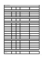
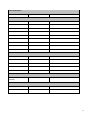
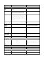
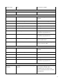
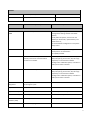
Statement of Volatility – Dell PowerEdge R820
Dell PowerEdge R820 contains both volatile and non-volatile (NV) components. Volatile components lose their
data immediately upon removal of power from the component. Non-volatile components continue to retain their
data even after the power has been removed from the component. Components chosen as user-definable
configuration options (those not soldered to the motherboard) are not included in the Statement of Volatility.
Configuration option information (pertinent to options such as microprocessors, remote access controllers, and
storage controllers) is available by component separately. The following NV components are present in the
PowerEdge R820 server.
Item
Non-Volatile or
Volatile
Quantity
Reference Designator
Size
PCH Internal
CMOS RAM
Non-Volatile
1
U104
256 Bytes
BIOS SPI Flash
Non-Volatile
1
U113
8 MB
iDRAC SPI Flash
Non-Volatile
1
U75
4 MB
BMC EMMC
Non-Volatile
1
U102
4 GB
CPU Vcore and
VSA Regulators
Non-Volatile
4
U11, U12 PLANAR
4.25 KB
System CPLD RAM
Volatile
1
U80
1 KB
System Memory
Volatile
Up to 12
per CPU
CPU<2:1>_CH<3:0>_D<2:0>
Up to 32GB per DIMM
Internal USB Key
Non-Volatile
Up to 1
N/A
Varies (not factory
installed)
Trusted Platform
Module (TPM)
Non-Volatile
1
U114(Plannar)
128 Bytes
PEM(FRU)
Non-Volatile
U114(PEM)
4k
Varies by part number
Up to 2MB. Varies by
part number
Planer
U11 U12 PEM
Power Supplies
PSU FW
03 - 2014
Non-Volatile
1 per PSU
8x2.5" Backplane
SEP internal flash
Non-Volatile
1
U_SEP
Flash:32KB+4KB EEPROM:
1KB
Flash memory
Non-Volatile
1
U33
32 Mb
Expander FRU image
Non-Volatile
1
U_EXP_EEPROM
512 Bytes
BP FRU image
Non-Volatile
1
U_BP_EEPROM
256 Bytes
Non-Volatile
1
U_SEP1
Flash:32KB+4KB EEPROM:
1KB
16x2.5" Backplane
PCIe SSD Backplane
SEP internal flash
H710, H810, H710M PERCs
NVSRAM
Non-volatile
1
U1033
128KB
FRU
Non-volatile
1
U1019
256B
1-Wire EEPROM
Non-volatile
1
U1004
128B
SPD
Non-volatile
1
U22
256B
SBR
Non-volatile
1
U1020
8KB
SPI Flash
Non-volatile
1
U1055
2MB
Flash
Non-volatile
1
U1031
16MB
ONFI Backup Flash
Non-volatile
1
U4
4GB
SDRAM
Volatile
5
U1043-U1047
512MB/1GB
NVSRAM
Non-volatile
1
U500
128KB
FRU
Non-volatile
1
U504
256B
1-Wire EEPROM
Non-volatile
1
U15
128B
SBR
Non-volatile
1
U503
8KB
Flash
Non-volatile
1
U3
16MB
1
U2
256B
H310, H310M PERCs
PCIe SSD Extension Card
Switch Configuration
EEPROM
Non-Volatile
2
IDSDM
SPI Flash
Non-Volatile
1
U9
8MB
MCU
Non-Volatile
1
U7
256KB
Item
Type (e.g. Flash PROM,
EEPROM)
Can user programs or operating system
write data to it during normal operation?
PCH Internal CMOS RAM
Battery-backed CMOS RAM
No
BIOS SPI Flash
SPI Flash
No
iDRAC SPI Flash
SPI Flash
No
BMC EMMC
eMMC NAND Flash
No
CPU Vcore and VSA
Regulators
OTP(one time programmable)
No
System CPLD RAM
RAM
No
System Memory
RAM
Yes
Internal USB Key
Flash
Yes
Trusted Platform Module
(TPM)
EEPROM
Yes
PEM FRU
EEPROM
No
Embedded microcontroller
flash
No
Integrated Flash+EEPROM
No
Flash memory
Flash
No
Expander FRU image
I2C EEPROM
No
BP FRU image
I2C EEPROM
No
Planer
Power Supplies
PSU FW
8x2.5" Backplane
SEP internal flash
16x2.5" Backplane
3
PCIe SSD Backplane
SEP internal flash
Integrated Flash+EEPROM
No
NVSRAM
NVSRAM
No
FRU
FRU
No
1-Wire EEPROM
1-Wire EEPROM
No
SPD
SPD
No
SBR
SBR
No
SPI Flash
SPI Flash
No
Flash
Flash
No
ONFI Backup Flash
ONFI Backup Flash
No
SDRAM
SDRAM
No
NVSRAM
NVSRAM
No
FRU
FRU
No
1-Wire EEPROM
1-Wire EEPROM
No
SBR
SBR
No
Flash
Flash
No
SPI Flash EEPROM
No (requires specialized SW)
SPI Flash
SPI Flash
No
MCU
Embedded Flash
FW can be updated via Linux and DOS
H710, H810, H710M PERCs
H310, H310M PERCs
PCIe SSD Extension Card
Switch Configuration
EEPROM
IDSDM
4
Item
Purpose? (e.g. boot code)
How is data input to this memory?
PCH Internal CMOS
RAM
Real-time clock and BIOS configuration
settings
BIOS
BIOS SPI Flash
Boot code, system configuration information,
UEFI environment, Flash descriptor, ME
SPI interface via iDRAC
iDRAC SPI Flash
iDRAC Uboot (bootloader), server
management persistent store (i.e. IDRAC
MAC Address, iDRAC boot variables), lifecycle
log cache, virtual planar FRU and EPPID, rac
log, system event log, JobStore, iDRAC Secure
boot code,
SPI interface via iDRAC
BMC EMMC
Operational iDRAC FW, Lifecycle Controller
(LC) USC partition, LC service diags, LC OS
drivers, USC firmware
NAND Flash interface via iDRAC
CPU Vcore and VSA
Regulators
Operational parameters
Once values are loaded into register
space a command writes to NVMEM.
System CPLD RAM
Not utilized
Not utilized
System Memory
System OS RAM
System OS
Internal USB Key
General purpose USB key drive
USB interface via PCH. Accessed via
system OS
Trusted Platform
Module (TPM)
Storage of encryption keys
Using TPM Enabled operating systems
PEM FRU
FRU
I2C interface via iDRAC
Power Supply operation, power management
data and fault behaviors
Different vendors have different utilities
and tools to load the data to memory. It
can also be loaded by Dell Update
Package from LC or OS (Windows and
Linux)
Planer
Power Supplies
PSU FW
8x2.5" Backplane
SEP internal flash
Firmware
16x2.5" Backplane
Flash memory
Firmware
Common Flash memory Interface (CFI)
Expander FRU image
FRU
I2C interface via iDRAC
5
BP FRU image
FRU
I2C interface via iDRAC
Firmware + FRU
I2C interface via iDRAC
PCIe SSD Backplane
SEP internal flash
H710, H810, H710M PERCs
NVSRAM
Configuration data
ROC writes configuration data to
NVSRAM
FRU
Card manufacturing information
Programmed at ICT during production.
1-Wire EEPROM
Holds default controller properties/settings
ROC writes data to this memory
SPD
Memory configuration data
Pre-programmed before assembly
SBR
Bootloader
Pre-programmed before assembly
SPI Flash
FPGA configuration data
Pre-programmed before assembly. Can
be updated using Dell/LSI tools
Flash
Card firmware
Pre-programmed before assembly. Can
be updated using Dell/LSI tools
ONFI Backup Flash
Holds cache data during power loss
FPGA backs up DDR data to this device in
case of a power failure
SDRAM
Cache for HDD I/O
ROC writes to this memory - using it as
cache for data IO to HDDs
NVSRAM
Configuration data
ROC writes configuration data to
NVSRAM
FRU
Card manufacturing information
Programmed at ICT during production
1-Wire EEPROM
Holds default controller properties/settings
ROC writes data to this memory
SBR
Bootloader
Pre-programmed before assembly
Flash
Card firmware
Pre-programmed before assembly. Can
be updated using Dell/LSI tools
H310, H310M PERCs
PCIe SSD Extension Card
Switch Configuration
EEPROM
Configuration for PLX PCIe switch, setting
registers
The EEPROM image is pre-loaded at
factory before assembly. Once
assembled on the card, data can be
entered via PLX Device Editor or PLX EEP
DOS based tool.
6
IDSDM
SPI Flash
Exclusively used by the controller
SPI interface via iDRAC
MCU
Firmware
USB interface via PCH
Item
How is this memory write protected?
How is the memory cleared?
PCH Internal CMOS
RAM
N/A – BIOS only control
1) Set NVRAM_CLR jumper to clear BIOS
configuration settings at boot and reboot
system;
2) AC power off system, remove coin cell
battery for 30 seconds, replace battery and
power back on;
3) restore default configuration in F2 system
setup menu.
BIOS SPI Flash
Software write protected
Not possible with any utilities or applications
and system is not functional if
corrupted/removed.
iDRAC SPI Flash
Embedded iDRAC subsystem firmware
actively controls sub area based write
protection as needed.
Not completely user clearable; however, user
data, lifecycle log and archive, SEL, fw image
repository can be cleared via Delete
Configuration and Retire System, accessible in
Lifecycle Controller interface
BMC EMMC
Embedded FW write protected
Not completely user clearable; however, user
data, lifecycle log and archive, SEL, fw image
repository can be cleared via Delete
Configuration and Retire System, accessible in
Lifecycle Controller interface
CPU Vcore and VSA
Regulators
There are passwords for different sections
of the register space
Not user clearable
System CPLD RAM
Not accessible
Not accessible
System Memory
OS Control
Reboot or power down system
Internal USB Key
No write protect
Can be cleared in system OS
Trusted Platform
Module (TPM)
SW write protected
F2 Setup option
PEM FRU
Hardware strapping
Not user clearable
Planer
7
Power Supplies
PSU FW
Protected by the embedded
microcontroller. Special keys are used by
special vendor provided utilities to unlock
the ROM with various CRC checks during
load.
Not clearable
Program write protect bit
Not user clearable
Flash memory
Hardware strapping
Not user clearable
Expander FRU image
Hardware strapping
Not user clearable
BP FRU image
Hardware strapping
Not user clearable
Program write protect bit
Not user clearable
8x2.5" Backplane
SEP internal flash
16x2.5" Backplane
PCIe SSD Backplane
SEP internal flash
H710, H810, H710M PERCs
NVSRAM
Not WP. Not visible to Host Processor
Cannot be cleared with existing tools available
to the customer
FRU
Not WP
Cannot be cleared with existing tools available
to the customer
1-Wire EEPROM
Not WP. Not visible to Host Processor
Cannot be cleared with existing tools available
to the customer
SPD
Not WP. Not visible to Host Processor
Cannot be cleared with existing tools available
to the customer
SBR
Not WP. Not visible to Host Processor
Cannot be cleared with existing tools available
to the customer
SPI Flash
Not WP. Not visible to Host Processor
Cannot be cleared with existing tools available
to the customer
Flash
Not WP. Not visible to Host Processor
Cannot be cleared with existing tools available
to the customer
ONFI Backup Flash
Not WP. Not visible to Host Processor
Flash can be cleared by powering up the card
and allowing the controller to flush the
contents to VDs. If the VDs are no longer
available, cache can be cleared by going into
controller bios and selecting Discard Preserved
Cache.
8
SDRAM
Not WP. Not visible to Host Processor
Cache can be cleared by powering off the card
NVSRAM
Not WP. Not visible to Host Processor
Cannot be cleared with existing tools available
to the customer
FRU
Not WP
Cannot be cleared with existing tools available
to the customer
1-Wire EEPROM
Not WP. Not visible to Host Processor
Cannot be cleared with existing tools available
to the customer
SBR
Not WP. Not visible to Host Processor
Cannot be cleared with existing tools available
to the customer
Flash
Not WP. Not visible to Host Processor
Cannot be cleared with existing tools available
to the customer
H310, H310M PERCs
PCIe SSD Extension Card
Switch Configuration
EEPROM
Device can be write protected via
hardware pin. Alternatively, device
contents can be write protected via WPEN
bit in status register.
System is not functional as intended if
corrupted/removed.
SPI Flash
Hardware strapping
Not user clearable
MCU
N/A
Not user clearable
IDSDM
NOTE: For any information that you may need, direct your questions to your Dell Marketing contact.
______________
© 2014 Dell Inc.
Trademarks used in this text: Dell™, the DELL logo, and PowerEdge™ are trademarks of Dell Inc.
9