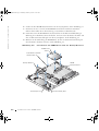
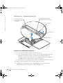
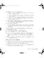
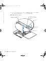
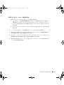
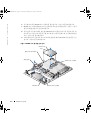
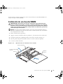
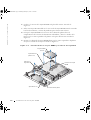
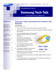
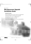
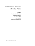
1
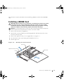
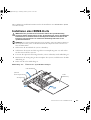
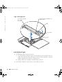
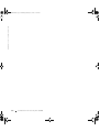
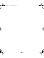
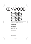
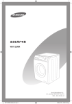
M0170fc0.fm Page 1 Tuesday, February 25, 2003 11:56 AM
Dell™ Systems
Installing a ROMB Card
安装 ROMB 卡
Installation de la carte ROMB
Installieren einer ROMB-Karte
ROMB カードの取り付け
ROMB 카드 설치
Instalación de una tarjeta ROMB
w w w. d e l l . c o m | s u p p o r t . d e l l . c o m
M0170fc0.fm Page 2 Tuesday, February 25, 2003 11:56 AM
M0170ebk0.book Page 1 Thursday, February 27, 2003 11:00 AM
Dell™ Systems
Installing a ROMB Card
w w w. d e l l . c o m | s u p p o r t . d e l l . c o m
M0170ebk0.book Page 2 Thursday, February 27, 2003 11:00 AM
Notes, Notices, and Cautions
NOTE: A NOTE indicates important information that helps you make better use of your computer.
NOTICE: A NOTICE indicates either potential damage to hardware or loss of data and tells you
how to avoid the problem.
CAUTION: A CAUTION indicates a potential for property damage, personal injury,
or death.
____________________
Information in this document is subject to change without notice.
© 2003 Dell Computer Corporation. All rights reserved.
Reproduction in any manner whatsoever without the written permission of Dell Computer Corporation is strictly forbidden.
Trademarks used in this text: Dell and the DELL logo are trademarks of Dell Computer Corporation.
Other trademarks and trade names may be used in this document to refer to either the entities claiming the marks and
names or their products. Dell Computer Corporation disclaims any proprietary interest in trademarks and trade names
other than its own.
March 2003
P/N M0170
Rev. A00
M0170ebk0.book Page 1 Thursday, February 27, 2003 11:00 AM
This document contains information about installing a RAID on mother board (ROMB)
card.
Installing a ROMB Card
CAUTION: Only trained service technicians are authorized to remove the system
cover and access any of the components inside the system. See your System
Information Guide for complete information about safety precautions, working
inside the computer, and protecting against electrostatic discharge.
NOTICE: To avoid possible data loss, back up all data on the hard drives before changing the
mode of operation of the integrated SCSI controller from SCSI to RAID.
1
Remove the front bezel (if applicable).
2
Turn off the system, including any attached peripherals, and disconnect the system
from the electrical outlet.
3
Remove the optional security screw (if applicable). See Figure 1-1.
4
Press the latch on the system front panel and lift the left cover.
5
Lift the right cover.
Figure 1-1.
Opening the System Covers
left cover
optional security screw
latch
right cover
Installing a ROMB Card
1-1
w w w. d e l l . c o m | s u p p o r t . d e l l . c o m
M0170ebk0.book Page 2 Thursday, February 27, 2003 11:00 AM
6
Locate the ROMB card connector on the system board. See Figure 1-2.
7
If a PCI card is installed over the ROMB card connector, remove it. See your
Installation and Troubleshooting Guide for instructions.
8
Position the ROMB card with the notch in its plastic cover facing the redundant power
supply bay, and align the edges of the card with the four plastic standoffs on the
system board. See Figure 1-2.
9
Press down on the ROMB card cover until the four plastic standoffs snap over the edge
of the card. See Figure 1-2.
Figure 1-2.
Installing the ROMB Card and Backup Battery
ROMB card
notch
plastic standoffs (4)
backup battery
ROMB card connector
standoffs (2)
1-2
Installing a ROMB Card
RAID_BAT connector
M0170ebk0.book Page 3 Thursday, February 27, 2003 11:00 AM
10
Install the ROMB backup battery:
a
Remove the SCSI backplane board. See "Removing the SCSI Backplane Board."
b
Position the battery board as shown in Figure 1-2, and press it down into the two
standoffs until it snaps into place.
c
Plug the battery cable into the RAID BAT connector on the system board.
d
Install the SCSI backplane board. See "Installing the SCSI Backplane Board."
11
If you removed a PCI card in step 7, replace it. See your Installation and
Troubleshooting Guide for instructions.
12
Close the system covers.
When closing the covers, close the right (larger) cover first and then close the left
cover. Press firmly on the left cover to snap the securing latch into place.
13
Install the optional security screw (if applicable). See Figure 1-1.
14
Install the front bezel (if applicable).
15
Reconnect the system and peripherals to their electrical outlets, and turn them on.
16
Enter the System Setup program and verify that the setting for the SCSI controller has
changed to reflect the presence of the RAID hardware. See "Using the System Setup
Program" in your User's Guide.
17
Configure the RAID card and logical drives. See the ROMB card documentation for
more information.
Removing the SCSI Backplane Board
1
Pull each hard-drive carrier partially out of its slot, approximately 2.5 cm (1 inch).
2
Disconnect the diskette-drive interface cable from the FLOPPY connector on the
backplane board. See Figure 1-3.
3
Disconnect the CD drive interface cable from the CD_ROM connector on the
backplane board. See Figure 1-3.
4
Press the release latch in toward the backplane board and use the handle to pull the
board out of its connector and up out of the chassis.
Installing a ROMB Card
1-3
M0170ebk0.book Page 4 Thursday, February 27, 2003 11:00 AM
w w w. d e l l . c o m | s u p p o r t . d e l l . c o m
Figure 1-3.
SCSI Backplane Board
CD drive interface
connector (CD_ROM)
diskette drive interface connector
(FLOPPY)
handle
release latch
tabs (2)
Installing the SCSI Backplane Board
1
1-4
Insert the SCSI backplane board into the chassis:
a
Fit the metal tabs (one tab at each end of the backplane) into the slots in the
chassis wall and lower the backplane into the chassis, ensuring that the CD and
diskette drive interface cables are not caught under the backplane.
b
Press down firmly over the handle to seat the backplane in its connector.
2
Pivot the release latch out into the securing slot in the chassis.
3
Connect the CD drive interface cable to the CD_ROM connector on the backplane
board. See Figure 1-3.
Installing a ROMB Card
M0170ebk0.book Page 5 Thursday, February 27, 2003 11:00 AM
4
Connect the diskette-drive interface cable to the FLOPPY connector on the backplane
board. See Figure 1-3.
5
Press all installed hard drives firmly back into the SCSI connectors on the backplane.
Installing a ROMB Card
1-5
w w w. d e l l . c o m | s u p p o r t . d e l l . c o m
M0170ebk0.book Page 6 Thursday, February 27, 2003 11:00 AM
1-6
Installing a ROMB Card
M0170cbk0.book Page 1 Tuesday, February 25, 2003 11:29 AM
Dell™ 系统
安装 ROMB 卡
w w w. d e l l . c o m | s u p p o r t . d e l l . c o m
M0170cbk0.book Page 2 Tuesday, February 25, 2003 11:29 AM
注 注意和警告
注
注表示可以帮助您更好地使用计算机的重要信息
注意
注意表示可能会损坏硬件或导致数据丢失
警告
警告表示存在可能导致财产损失 人身伤害或死亡的潜在危险
并告诉您如何避免此类问题
____________________
本文件中的信息如有更改 恕不另行通知
© 2003 Dell Computer Corporation 版权所有
未经 Dell Computer Corporation 书面许可
本文件中使用的商标
翻印必究
不准以任何形式进行复制
Dell 和 DELL 徽标是 Dell Computer Corporation 的商标
本文件中述及的其它商标和产品名称是指拥有相应商标和名称的公司或其制造的产品
Corporation 对其它公司的商标和产品名称不拥有任何专利权
2003 年 3 月
P/N M0170 Rev. A00
Dell Computer
M0170cbk0.book Page 1 Tuesday, February 25, 2003 11:29 AM
本说明文件包含有关安装母板板载 RAID (ROMB) 卡的信息
安装 ROMB 卡
警告
仅有经培训的维修技术人员才有权卸下主机盖并拆装系统内部的任何组件 有关安全
预防措施 拆装计算机内部组件以及防止静电损害的完整信息 请参阅 系统信息指南
注意
为避免丢失数据 请在将集成 SCSI 控制器的操作模式从 SCSI 更改为 RAID 之前先
备份硬盘驱动器上的所有数据
1
卸下前挡板
2
关闭系统
3
卸下可选固定螺钉
4
按下系统前面板上的闩锁
5
提起右侧机盖
图 2-1
如果适用
包括连接的任何外围设备
如果适用
然后断开系统与电源插座的连接
请参见图 2-1
然后提起左侧机盖
打开主机盖
左侧机盖
可选固定螺钉
闩锁
右侧机盖
安装 ROMB 卡
2-1
w w w. d e l l . c o m | s u p p o r t . d e l l . c o m
M0170cbk0.book Page 2 Tuesday, February 25, 2003 11:29 AM
6
找到主机板上的 ROMB 卡连接器
7
如果 ROMB 卡连接器上已安装了 PCI 卡 请将其卸下 有关说明 请参阅
与故障排除指南
8
定位 ROMB 卡 使其塑料护盖中的槽口朝向冗余电源设备托架 然后将插卡边缘与
主机板上的四个塑料定位器对齐 请参见图 2-2
9
向下按压 ROMB 卡护盖
图 2-2
请参见图 2-2
直至四个塑料定位器卡在插卡边缘上
安装
请参见图 2-2
安装 ROMB 卡和备用电池
ROMB 卡
槽口
塑料定位器
4个
备用电池
定位器
2-2
安装 ROMB 卡
ROMB 卡连接器
2个
RAID_BAT 连接器
M0170cbk0.book Page 3 Tuesday, February 25, 2003 11:29 AM
10
安装 ROMB 备用电池
a
卸下 SCSI 底板
请参阅
卸下 SCSI 底板
b
如图 2-2 所示定位电池板
c
将电池电缆插入主机板上的 RAID BAT 连接器
d
安装 SCSI 底板
然后将其向下按入两个定位器直至卡入到位
请参阅
安装 SCSI 底板
11
如果您在步骤 7 中卸下了 PCI 卡 请将其装回 有关说明 请参阅 安装与故障排
除指南
12
关闭主机盖
关闭主机盖时 请先关闭右侧 较大 主机盖
按压左侧主机盖 使固定闩锁卡入到位
如果适用
然后再关闭左侧主机盖
稳定地
13
安装可选固定螺钉
请参见图 2-1
14
安装前挡板
15
将系统和外围设备重新连接至电源插座
16
进入系统设置程序 然后验证 SCSI 控制器的设置是否已更改为显示存在 RAID 硬
件 请参阅 用户指南 中的 使用系统设置程序
17
配置 RAID 卡和逻辑驱动器
如果适用
有关详情
然后开机
请参阅 ROMB 卡说明文件
卸下 SCSI 底板
1
将每个硬盘驱动器托盘从其插槽中部分拉出
大约拉出 2.5 厘米
2
从底板上的 FLOPPY 连接器中断开软盘驱动器接口电缆的连接
3
从底板上的 CD_ROM 连接器中断开 CD 驱动器接口电缆的连接
4
将释放闩锁朝底板方向按下 然后使用手柄将底板从连接器中拉出并从机箱中取出
1 英寸
请参见图 2-3
请参见图 2-3
安装 ROMB 卡
2-3
M0170cbk0.book Page 4 Tuesday, February 25, 2003 11:29 AM
w w w. d e l l . c o m | s u p p o r t . d e l l . c o m
图 2-3
SCSI 底板
软盘驱动器接口连接器
(FLOPPY)
CD 驱动器接口连接
器 (CD_ROM)
手柄
释放闩锁
卡舌
2个
安装 SCSI 底板
1
2-4
将 SCSI 底板插入机箱
a
将金属卡舌 底板每端各一个 套入机箱壁上的槽孔中 然后将底板向下放
入机箱 并确保 CD 和软盘驱动器接口电缆不会被压在底板下
b
稳定地向下按压手柄
使底板在其连接器中就位
2
将释放闩锁向外转入机箱上的固定槽孔中
3
将 CD 驱动器接口电缆连接至底板上的 CD_ROM 连接器
4
将软盘驱动器接口电缆连接至底板上的 FLOPPY 连接器
5
将所有已安装的硬盘驱动器稳定地按入底板上的 SCSI 连接器中
安装 ROMB 卡
请参见图 2-3
请参见图 2-3
M0170fbk0.book Page 1 Thursday, February 27, 2003 11:01 AM
Systèmes Dell™
Installation de la carte
ROMB
w w w. d e l l . c o m | s u p p o r t . d e l l . c o m
M0170fbk0.book Page 2 Thursday, February 27, 2003 11:01 AM
Remarques, mises en garde et avertissements
REMARQUE : Une REMARQUE indique une information importante destinée à vous aider à
mieux utiliser votre ordinateur.
MISE EN GARDE : Une MISE EN GARDE indique un dommage ou une perte de données
potentiels pouvant survenir et comment éviter ce problème.
ATTENTION : Le message ATTENTION indique une situation potentiellement
dangereuse qui, si elle n'est pas évitée, peut provoquer une détérioration du
matériel ou des blessures pouvant entraîner la mort.
____________________
Les informations fournies dans ce document sont susceptibles d'être modifiées sans préavis.
© 2003 Dell Computer Corporation. Tous droits réservés.
La reproduction de ce document de quelque manière que ce soit sans l'autorisation écrite de Dell Computer Corporation
est strictement interdite.
Marques utilisées dans ce document : Dell et le logo DELL sont des marques de Dell Computer Corporation.
Tous les autres noms de marques et marques commerciales utilisés dans ce document se rapportent aux sociétés propriétaires
des marques et des noms de ces produits. Dell Computer Corporation décline tout intérêt dans l'utilisation des marques
déposées et des noms de marques ne lui appartenant pas.
Mars 2003
Réf M0170
Rév. A00
M0170fbk0.book Page 1 Thursday, February 27, 2003 11:01 AM
Ce document contient des informations sur l'installation d'une carte RAID sur une carte
mère (ROMB).
Installation de la carte ROMB
ATTENTION : Seuls les techniciens de maintenance qualifiés sont habilités à
retirer le capot du système et à accéder aux composants du système. Reportezvous au Guide Informations sur le système pour obtenir des informations
complètes sur les précautions en matière de sécurité, les opérations à effectuer à
l'intérieur de l'ordinateur et la protection contre l'électricité statique.
MISE EN GARDE : Pour éviter toute perte de données, sauvegardez toutes les données sur les
disques durs avant de modifier le mode de fonctionnement du contrôleur SCSI intégré pour le
faire passer de SCSI à RAID.
1
Retirez le cache avant (le cas échéant).
2
Mettez le système hors tension, y compris les périphériques qui y sont connectés, puis
débranchez-le du secteur.
3
Retirez la vis de sécurité en option (le cas échéant). Voir la Figure 3-1.
4
Appuyez sur le loquet situé sur le panneau avant du système et soulevez le capot
gauche.
5
Soulevez le capot droit.
Figure 3-1.
Ouverture des capots du système
capot gauche
vis de sécurité en option
loquet
capot droit
Installation de la carte ROMB
3-1
w w w. d e l l . c o m | s u p p o r t . d e l l . c o m
M0170fbk0.book Page 2 Thursday, February 27, 2003 11:01 AM
6
Repérez le connecteur de la carte ROMB sur la carte système. Voir la Figure 3-2.
7
Si une carte PCI est installée sur le connecteur de la carte ROMB, retirez-la. Reportezvous au Guide d'installation et de dépannage pour plus d'informations.
8
Positionnez la carte ROMB de sorte que l'encoche de son couvercle en plastique se
retrouve face à la baie du module d'alimentation redondant, puis alignez les bords de
la carte sur les quatre picots en plastique de la carte système. Voir la Figure 3-2.
9
Appuyez sur le couvercle de la carte ROMB jusqu'à ce que son rebord s'encastre sur les
quatre picots en plastique. Voir la Figure 3-2.
Figure 3-2.
ROMB
Installation de la carte et de la batterie de sauvegarde
carte ROMB
encoche
picots en plastique (4)
batterie de
sauvegarde
connecteur de la carte
ROMB
picots (2)
3-2
Installation de la carte ROMB
connecteur RAID_BAT
M0170fbk0.book Page 3 Thursday, February 27, 2003 11:01 AM
10
Installez la batterie de sauvegarde ROMB :
a
Retirez la carte de fond de panier SCSI. Voir « Retrait de la carte de fond de panier
SCSI ».
b
Positionnez la carte de la batterie comme indiqué à la Figure 3-2 et appuyez
dessus jusqu'à ce qu'elle s'encastre sur les deux picots.
c
Branchez le câble de la batterie sur le connecteur RAID BAT de la carte système.
d
Installez la carte de fond de panier SCSI. Voir « Installation de la carte de fond de
panier SCSI ».
11
Si vous aviez retiré une carte PCI à l'étape 7, replacez-la. Reportez-vous au Guide
d'installation et de dépannage pour plus d'informations.
12
Refermez les capots du système.
Lorsque vous refermez les capots, commencez par le capot droit (plus grand), puis le
capot gauche. Appuyez fermement sur le capot gauche pour bien enclencher le loquet
de fixation.
13
Installez la vis de sécurité en option (le cas échéant). Voir la Figure 3-1.
14
Installez le cache avant (le cas échéant).
15
Rebranchez le système et les périphériques sur le secteur, puis remettez-les sous
tension.
16
Accédez au programme de configuration du système (System Setup) et vérifiez que le
paramètre du contrôleur SCSI a changé et qu'il prend bien en compte la présence du
matériel RAID. Reportez-vous à la section « Utilisation du programme System Setup »
du Guide de l'utilisateur.
17
Configurez la carte et les unités logiques RAID. Pour plus d'informations, reportezvous à la documentation de la carte ROMB.
Retrait de la carte de fond de panier SCSI
1
Retirez d'environ 2,5 cm chaque support de disque dur de son emplacement.
2
Débranchez le câble d'interface du lecteur de disquette du connecteur FLOPPY sur la
carte de fond de panier. Voir la Figure 3-3.
3
Débranchez le câble d'interface du lecteur de CD du connecteur CD_ROM sur la
carte de fond de panier. Voir la Figure 3-3.
4
Appuyez sur le loquet de dégagement en direction de la carte de fond de panier et
retirez la carte de son connecteur et du châssis à l'aide de la poignée.
Installation de la carte ROMB
3-3
M0170fbk0.book Page 4 Thursday, February 27, 2003 11:01 AM
w w w. d e l l . c o m | s u p p o r t . d e l l . c o m
Figure 3-3.
Carte de fond de panier SCSI
connecteur d'interface
du lecteur de CD
(CD_ROM)
connecteur d'interface du lecteur
de disquette (FLOPPY)
poignée
loquet de
dégagement
pattes (2)
Installation de la carte de fond de panier SCSI
1
2
3-4
Insérez la carte de fond de panier SCSI dans le châssis :
a
Introduisez les pattes métalliques (une patte à chaque extrémité du fond de
panier) dans les emplacements prévus à cet effet sur la paroi du châssis, puis
appuyez sur le fond de panier pour le placer dans le châssis, en veillant à ce que les
câbles d'interface du lecteur de CD et de disquette ne soient pas coincés dessous.
b
Appuyez fermement sur la poignée pour enclencher le fond de panier dans son
connecteur.
Faites pivoter le loquet de dégagement dans l'emplacement de fixation du châssis.
Installation de la carte ROMB
M0170fbk0.book Page 5 Thursday, February 27, 2003 11:01 AM
3
Branchez le câble d'interface du lecteur de CD sur le connecteur CD_ROM de la carte
de fond de panier. Voir la Figure 3-3.
4
Branchez le câble d'interface du lecteur de disquette sur le connecteur FLOPPY de la
carte de fond de panier. Voir la Figure 3-3.
5
Appuyez sur tous les disques durs installés sur les connecteurs SCSI du fond de panier
pour les replacer correctement.
Installation de la carte ROMB
3-5
w w w. d e l l . c o m | s u p p o r t . d e l l . c o m
M0170fbk0.book Page 6 Thursday, February 27, 2003 11:01 AM
3-6
Installation de la carte ROMB
M0170gbk0.book Page 1 Thursday, February 27, 2003 11:02 AM
Dell™-Systeme
Installieren einer
ROMB-Karte
w w w. d e l l . c o m | s u p p o r t . d e l l . c o m
M0170gbk0.book Page 2 Thursday, February 27, 2003 11:02 AM
Anmerkung, Hinweis und Vorsicht
ANMERKUNG: Eine ANMERKUNG enthält wichtige Informationen, mit deren Hilfe Sie Ihren
Computer besser nutzen können.
HINWEIS: Mit einem HINWEIS wird auf eine mögliche Beschädigung von Hardware oder den
Verlust von Daten hingewiesen und erläutert, wie dieses Problem vermieden werden kann.
VORSICHT: VORSICHT weist darauf hin, dass Gefahr eines Sach- oder
Personenschadens oder Lebensgefahr besteht.
____________________
Die in diesem Dokument enthaltenen Informationen können ohne Vorankündigung geändert werden.
© 2003 Dell Computer Corporation. Alle Rechte vorbehalten.
Eine Reproduktion dieses Dokuments in jeglicher Form ist nur mit vorheriger schriftlicher Genehmigung der Dell Computer
Corporation erlaubt.
Die im Text enthaltenen Marken Dell und das DELL-Logo sind Marken der Dell Computer Corporation.
Andere in diesem Dokument möglicherweise verwendete Marken und Handelsbezeichnungen sind unter Umständen
Marken und Namen der entsprechenden Firmen oder ihrer Produkte. Die Dell Computer Corporation erhebt keinen
Anspruch auf Marken und Handelsnamen mit Ausnahme ihrer eigenen.
März 2003
Teile-Nr. M0170
Rev. A00
M0170gbk0.book Page 1 Thursday, February 27, 2003 11:02 AM
Dieses Dokument enthält Informationen über das Installieren einer ROMB-Karte (RAID
on mother board).
Installieren einer ROMB-Karte
VORSICHT: Nur geschulte Servicetechniker dürfen die Systemabdeckung
entfernen und die Komponenten auf der Systeminnenseite warten. Ausführliche
Informationen zu den Sicherheitsvorkehrungen beim Arbeiten im Inneren des
Computers und zum Schutz vor elektrischer Entladung finden Sie in den
Systeminformationen.
HINWEIS: Um einen eventuellen Datenverlust zu vermeiden, sollten Sie sämtliche Daten auf
den Festplatten sichern, bevor Sie den Betriebsmodus des integrierten SCSI-Controllers von
SCSI auf RAID ändern.
1
Nehmen Sie die Frontblende ab (sofern vorhanden).
2
Schalten Sie das System und alle angeschlossenen Peripheriegeräte aus, und ziehen
Sie den Netzstecker des Systems.
3
Lösen Sie die optionale Sicherungsschraube (sofern vorhanden). Siehe Abbildung 4-1.
4
Drücken Sie die Verriegelung an der Frontplatte des Systems, und heben Sie die linke
Abdeckung an.
5
Heben Sie die rechte Abdeckung an.
Abbildung 4-1.
Öffnen der Systemabdeckungen
linke Abdeckung
optionale
Sicherungsschraube
Verriegelung
rechte
Abdeckung
I ns tallie r e n e ine r R OMB -K ar te
4-1
w w w. d e l l . c o m | s u p p o r t . d e l l . c o m
M0170gbk0.book Page 2 Thursday, February 27, 2003 11:02 AM
6
Suchen Sie den ROMB-Kartenanschluss auf der Systemplatine. Siehe Abbildung 4-2.
7
Entfernen Sie eine eventuell am ROMB-Kartenanschluss installierte PCI-Karte.
Näheres dazu finden Sie in der Anleitung zur Installation und Fehlersuche.
8
Positionieren Sie die ROMB-Karte mit dem Schlitz in der Kunststoffabdeckung in
Richtung des redundanten Netzteilschachts, und setzen Sie die Kanten der Karte mit
den vier Kunststoff-Anschlusspolen an die Systemplatine. Siehe Abbildung 4-2.
9
Drücken Sie die Abdeckung der ROMB-Karte, bis die vier Kunststoff-Anschlusspole
über der Kante der Karte einrasten. Siehe Abbildung 4-2.
Abbildung 4-2.
Installieren der ROMB-Karte und der Backup-Batterie
ROMB-Karte
Schlitz
freistehende KunststoffAnschlusspole (4)
ROMBKartenanschluss
Backup-Batterie
Anschlusspole (2)
4-2
Installieren einer ROMB -Karte
Anschluss RAID_BAT
M0170gbk0.book Page 3 Thursday, February 27, 2003 11:02 AM
10
Installieren der ROMB-Backup-Batterie:
a
Entfernen Sie die SCSI-Rückwandplatine. Siehe hierzu "Entfernen der SCSIRückwandplatine".
b
Positionieren Sie die Batterieplatine wie in Abbildung 4-2 dargestellt, und drücken
Sie diese in die zwei Anschlusspole, bis sie einrastet.
c
Schließen Sie das Batteriekabel am Anschluss RAID BAT auf der Systemplatine
an.
d
Installieren Sie die SCSI-Rückwandplatine. Siehe hierzu "Installieren der SCSIRückwandplatine".
11
Wenn Sie in Schritt 7 eine PCI-Karte entfernt haben, können Sie diese jetzt wieder
einsetzen. Näheres dazu finden Sie in der Anleitung zur Installation und Fehlersuche.
12
Schließen Sie die Systemabdeckungen.
Wenn Sie die Abdeckung schließen, müssen Sie bei der rechten (größeren) Abdeckung
beginnen und dann die linke Abdeckung schließen. Drücken Sie fest gegen die linke
Abdeckung, damit die Sicherheitsverriegelung einrasten kann.
13
Ziehen Sie die optionale Sicherungsschraube an (sofern vorhanden). Siehe
Abbildung 4-1.
14
Setzen Sie die Frontblende ein (sofern vorhanden).
15
Verbinden Sie das System und die Peripheriegeräte wieder mit der Stromversorgung,
und schalten Sie das System und die Geräte ein.
16
Rufen Sie das System-Setup-Programm auf und überprüfen Sie, ob die RAIDHardware in den Einstellungen für den SCSI-Controller aufgenommen wurde. Siehe
auch "Verwendung des System-Setup-Programms" im Benutzerhandbuch.
17
Konfigurieren Sie die RAID-Karte und die logischen Laufwerke. Nähere
Informationen hierzu finden Sie in der ROMB-Kartendokumentation.
Entfernen der SCSI-Rückwandplatine
1
Ziehen Sie jeden Festplattenträger teilweise aus seinem Schlitz (ca. 2,5 cm).
2
Trennen Sie das Schnittstellenkabel des Diskettenlaufwerks vom Anschluss FLOPPY
der Rückwandplatine. Siehe Abbildung 4-3.
3
Trennen Sie das Schnittstellenkabel des CD-ROM-Laufwerks vom Anschluss
CD_ROM der Rückwandplatine. Siehe Abbildung 4-3.
4
Drücken Sie die Sperrklinke in Richtung der Rückwandplatine, und ziehen Sie die
Platine am Handgriff aus ihren Anschlüssen und dann aus dem Gehäuse.
I ns tallie r e n e ine r R OMB -K ar te
4-3
M0170gbk0.book Page 4 Thursday, February 27, 2003 11:02 AM
w w w. d e l l . c o m | s u p p o r t . d e l l . c o m
Abbildung 4-3.
SCSI-Rückwandplatine
Schnittstellenanschluss
für CD-ROM-Laufwerke
(CD_ROM)
Schnittstellenanschluss für
Diskettenlaufwerke (FLOPPY)
Handgriff
Sperrklinke
Zungen (2)
Installieren der SCSI-Rückwandplatine
1
4-4
Setzen Sie die SCSI-Rückwandplatine in das Gehäuse ein:
a
Setzen Sie die Metallzungen (eine Zunge an jedem Ende der Rückwand) in die
Schlitze an der Gehäusewand ein, und schieben Sie die Rückwand in das
Gehäuse. Achten Sie dabei darauf, dass die Schnittstellenkabel des CD-ROMund Diskettenlaufwerks nicht hinter der Rückwand liegen.
b
Drücken Sie fest am Handgriff, um die Rückwand in ihren Anschluss einzusetzen.
2
Kippen Sie die Sperrklinke in den Sicherungsschlitz im Gehäuse.
3
Schließen Sie das Schnittstellenkabel des CD-ROM-Laufwerks am Anschluss
CD_ROM auf der Rückwandplatine an. Siehe Abbildung 4-3.
Installieren einer ROMB -Karte
M0170gbk0.book Page 5 Thursday, February 27, 2003 11:02 AM
4
Schließen Sie das Schnittstellenkabel des Diskettenlaufwerks am Anschluss FLOPPY
auf der Rückwandplatine an. Siehe Abbildung 4-3.
5
Drücken Sie alle installierten Festplatten wieder fest in die SCSI-Anschlüsse der
Rückwand.
I ns tallie r e n e ine r R OMB -K ar te
4-5
w w w. d e l l . c o m | s u p p o r t . d e l l . c o m
M0170gbk0.book Page 6 Thursday, February 27, 2003 11:02 AM
4-6
Installieren einer ROMB -Karte
M0170jbk0.book Page 1 Tuesday, February 25, 2003 11:22 AM
Dell™ システム
ROMB カードの
取り付け
w w w. d e l l . c o m | s u p p o r t . d e l l . c o m
M0170jbk0.book Page 2 Tuesday, February 25, 2003 11:22 AM
メモ、注意および警告
メモ:メモは、コンピュータを使いやすくするための重要な情報を説明しています。
注意:注意は、ハードウェアの損傷やデータの損失の可能性があることを示し、その危険
を回避するための方法を説明しています。
警告:警告は、物的損害、けが、または死亡の原因となる可能性があることを示します。
____________________
ここに記載されている内容は予告なく変更されることがあります。
© 2003 すべての著作権は Dell Computer Corporation にあります。
Dell Computer Corporation の書面による許可のない複写は、いかなる形態においても厳重に禁じられてい
ます。
本書で使用されている商標について:Dell および DELL ロゴは、Dell Computer Corporation の商標です。
本書では、必要に応じて上記記載以外の商標および会社名が使用されている場合がありますが、これらの商
標や会社名は、一切 Dell Computer Corporation に所属するものではありません。
2003 年 3 月
P/N M0170 Rev. A00
M0170jbk0.book Page 1 Tuesday, February 25, 2003 11:22 AM
本書では、ROMB(RAID on mother board)カードの取り付けに関する情報について
説明します。
ROMB カードの取り付け
警告:トレーニングを受けたサービス技術者以外は、システムカバーを取り外して、シス
テム内部のコンポーネントに触れることが許されていません。安全に関する注意、コン
ピュータ内部での作業、静電気障害への対処の詳細については、
『システム情報ガイド』を
参照してください。
注意:データの損失を避けるため、内蔵 SCSI コントローラの動作モードを SCSI から RAID
に変更する前に、ハードドライブの全データをバックアップしてください。
1
前面ベゼルを取り付けている場合は、ベゼルを取り外します。
2
システムの電源を切り、システムに接続されているすべての周辺機器の電源を
切って、システムを電源コンセントから取り外します。
3
オプションのセキュリティ用ネジを取り付けている場合は、ネジを外します。
図 5-1 を参照してください。
4
システムの正面パネルのラッチを押し、左側のカバーを持ち上げます。
5
右側のカバーを持ち上げます。
図 5-1. システムのカバーを開く
左側のカバー
オプションの
セキュリティ用ネジ
ラッチ
右側のカバー
ROMB カードの取り付け
5-1
w w w. d e l l . c o m | s u p p o r t . d e l l . c o m
M0170jbk0.book Page 2 Tuesday, February 25, 2003 11:22 AM
6
システム基板の ROMB カードコネクタの位置を確認します。図 5-2 を参照して
ください。
7
PCI カードが ROMB カードコネクタにすでに取り付けられている場合は、PCI カー
ドを取り外します。手順については、
『Installation and Troubleshooting Guide』
(インストール & トラブルシューティングガイド)を参照してください。
8
ROMB カードを、プラスチックカバーの切り込みが冗長電源装置ベイを向くよ
うに配置し、カードの四隅をシステム基板上の 4 つのプラスチックの突起にはめ
込みます。図 5-2 を参照してください。
9
4 つのプラスチックの突起がカードの端にカチっとはまるまで、ROMB カードの
カバーを押し込みます。図 5-2 を参照してください。
図 5-2. ROMB カードとバックアップバッテリの取り付け
ROMB カード
切り込み
プラスチック突起(4)
バックアップ
バッテリ
突起(2)
5-2
ROMB カードの取り付け
ROMB カード
コネクタ
RAID_BAT コネクタ
M0170jbk0.book Page 3 Tuesday, February 25, 2003 11:22 AM
10
ROMB バックアップバッテリを取り付けます。
a
SCSI バックプレーンボードを取り外します。「SCSI バックプレーンボードの
取り外し」を参照してください。
b
バッテリボードを図 5-2 に示すように配置し、2 つの突起にカチッとはまる
まで押し込みます。
c
バッテリケーブルをシステム基板上の RAID_BAT コネクタに差し込みます。
d
SCSI バックプレーンボードを取り付けます。「SCSI バックプレーンボードの
取り付け」を参照してください。
11
手順 7 で PCI カードを取り外した場合は、カードを取り付けます。手順につい
(インストール & トラブル
ては、『Installation and Troubleshooting Guide』
シューティングガイド)を参照してください。
12
システムのカバーを閉じます。
カバーを閉じる場合は、まず右側(大きい方)のカバーを閉じ、それから左側の
カバーを閉じます。左側のカバーを、固定ラッチがカチッとはまるまでしっかり
と押し込みます。
13
オプションのセキュリティ用ネジを取り付ける場合は、ネジを取り付けます。
図 5-1 を参照してください。
14
前面ベゼルを取り付ける場合は、ベゼルを取り付けます。
15
システムと周辺機器をコンセントに接続し、電源を入れます。
16
セットアップユーティリティを起動し、SCSI コントローラの設定が変更され、
RAID ハードウェアが認識されていることを確認します。システムに付属の
『ユーザーズガイド』の「セットアップユーティリティの使い方」を参照してく
ださい。
17
RAID カードと論理ドライブを設定します。詳細については、ROMB カードのマ
ニュアルを参照してください。
SCSI バックプレーンボードの取り外し
1
それぞれのハードドライブキャリアを、スロットから約 2.5 cm 引き出します。
2
ディスケットドライブインタフェースケーブルを、バックプレーンボードの
FLOPPY コネクタから取り外します。図 5-3 を参照してください。
3
CD ドライブインタフェースケーブルを、バックプレーンボードの CD_ROM コネク
タから取り外します。図 5-3 を参照してください。
ROMB カードの取り付け
5-3
w w w. d e l l . c o m | s u p p o r t . d e l l . c o m
M0170jbk0.book Page 4 Tuesday, February 25, 2003 11:22 AM
4
リリースラッチをバックプレーンボードの方向に押し込み、ハンドルを使って
ボードをコネクタから取り外し、シャーシから引き上げます。
図 5-3. SCSI バックプレーンボード
CD ドライブインタフェース
コネクタ(CD_ROM)
ディスケットドライブ
インタフェースコネクタ
(FLOPPY)
ハンドル
リリース
ラッチ
タブ(2)
5-4
ROMB カードの取り付け
M0170jbk0.book Page 5 Tuesday, February 25, 2003 11:22 AM
SCSI バックプレーンボードの取り付け
1
SCSI バックプレーンボードをシャーシに取り付けます。
a
バックプレーンの両端の金属製のタブをシャーシ側面のスロットに合わせ、
CD およびディスケットドライブのインタフェースケーブルがバックプレー
ンの下にはさまれないように確認しながら、バックプレーンをシャーシに下
ろします。
b
ハンドルごしにバックプレーンをしっかりと下に押し込んで、コネクタに固
定します。
2
リリースラッチをシャーシの固定スロットにしっかりと押し込みます。
3
CD ドライブインタフェースケーブルを、バックプレーンボードの CD_ROM コネ
クタに接続します。図 5-3 を参照してください。
4
ディスケットドライブインタフェースケーブルを、バックプレーンボードの
FLOPPY コネクタに接続します。図 5-3 を参照してください。
5
取り付けられていたハードドライブをすべて、バックプレーンの SCSI コネクタ
にしっかりと取り付けます。
ROMB カードの取り付け
5-5
w w w. d e l l . c o m | s u p p o r t . d e l l . c o m
M0170jbk0.book Page 6 Tuesday, February 25, 2003 11:22 AM
5-6
ROMB カードの取り付け
M0170kbk0.book Page 1 Tuesday, February 25, 2003 12:02 PM
Dell™ 시스템
ROMB 카드 설치
w w w. d e l l . c o m | s u p p o r t . d e l l . c o m
M0170kbk0.book Page 2 Tuesday, February 25, 2003 12:02 PM
주, 주의사항 및 주의
주: 주는 컴퓨터를 보다 효율적으로 사용할 수 있는 중요 정보를 제공합니다.
주의사항: 주의사항은 하드웨어의 손상 또는 데이타 유실 위험을 설명하며, 이러한 문제를
방지할 수 있는 방법을 알려줍니다.
주의: 주의는 위험한 상황, 심각한 부상 또는 사망할 우려가 있음을 알려줍니다.
____________________
본 설명서에 수록된 정보는 사전 통보 없이 변경될 수 있습니다.
© 2003 Dell Computer Corporation. 저작권 본사 소유.
Dell Computer Corporation의 서면 승인 없이 어떠한 방법으로도 무단 복제하는 것을 엄격히 금합니다.
본 설명서에 사용된 상표: Dell 및 DELL 로고는 Dell Computer Corporation의 상표입니다.
본 설명서에서 특정 회사의 표시나 제품 이름을 지칭하기 위해 기타 상표나 상호를 사용할 수도 있습니다. Dell
Computer Corporation은 자사가 소유하고 있는 것 이외의 다른 모든 등록 상표 및 상표명에 대한 어떠한 소유권
도 없음을 알려 드립니다.
2003년 3월
P/N M0170 Rev. A00
M0170kbk0.book Page 1 Tuesday, February 25, 2003 12:02 PM
본 설명서에서는 마더보드(ROMB) 카드에 RAID를 설치하는 방법을 설명합니다.
ROMB 카드 설치
주의: 숙련된 서비스 기술자만 시스템 덮개를 분리하고 시스템 내부의 구성요소에 액세스
해야 합니다. 안전 지침, 컴퓨터 내부 작업 및 정전기 방전 방지에 대한 자세한 내용은
≪시스템 정보 설명서≫를 참조하십시오.
주의사항: 데이타 손실을 방지하려면 내장형 SCSI 컨트롤러의 작동 모드를 SCSI에서
RAID로 변경하기 전에 하드 드라이브에 모든 데이타를 백업해두십시오.
1
전면 베젤을 분리하십시오(해당되는 경우).
2
시스템과 시스템에 연결된 모든 주변장치의 전원을 끄고 전원 콘센트에서 시스템
을 분리하십시오.
3
고정 나사 옵션을 분리하십시오(해당되는 경우). 그림 6-1을 참조하십시오.
4
시스템의 전면 패널에 있는 래치를 누르고 왼쪽 덮개를 들어올리십시오.
5
오른쪽 덮개를 들어올리십시오.
그림 6-1. 시스템 덮개 열기
왼쪽 덮개
고정 나사 옵션
래치
오른쪽 덮개
ROMB 카드 설치
6-1
w w w. d e l l . c o m | s u p p o r t . d e l l . c o m
M0170kbk0.book Page 2 Tuesday, February 25, 2003 12:02 PM
6
시스템 보드에서 ROMB 카드 커넥터를 찾으십시오. 그림 6-2를 참조하십시오.
7
ROMB 카드 커넥터에 PCI 카드가 설치되어 있으면 분리하십시오. 지침은 ≪설치
및 문제 해결 설명서≫를 참조하십시오.
8
중복 전원 공급 장치 베이 맞은편에 ROMB 카드의 플라스틱 노치 부분이 마주 보
이도록 놓고 카드 모서리를 시스템 보드에 있는 4개의 플라스틱 지지대와 맞추십
시오. 그림 6-2를 참조하십시오.
9
4개의 플라스틱 지지대가 카드 모서리에 맞물릴 때까지 ROMB 카드 덮개를 누르
십시오. 그림 6-2를 참조하십시오.
그림 6-2. ROMB 카드 및 백업 전지 설치
ROMB 카드
노치
플라스틱 지지대(4)
백업 전지
ROMB 카드 커넥터
지지대(2)
6-2
ROMB 카드 설치
RAID_BAT 커넥터
M0170kbk0.book Page 3 Tuesday, February 25, 2003 12:02 PM
10
ROMB 백업 전지를 설치하십시오:
a
SCSI 후면판 보드를 분리하십시오. 「SCSI 후면판 보드 분리」를 참조하십시오.
b
전지 보드를 그림 6-2처럼 놓은 다음 2개의 지지대에 눌러 끼우십시오.
c
전지 케이블을 시스템 보드의 RAID BAT 커넥터에 연결하십시오.
d
SCSI 후면판 보드를 설치하십시오. 「SCSI 후면판 보드 설치」를 참조하십시오.
11
PCI 카드를 7단계에서 분리한 경우 다시 끼우십시오. 지침은 ≪설치 및 문제 해결
설명서≫를 참조하십시오.
12
시스템 덮개를 닫으십시오.
덮개를 닫을 때 오른쪽(더 큰) 덮개를 먼저 닫고 왼쪽 덮개를 닫으십시오. 왼쪽 덮
개를 꽉 눌러 래치를 고정시키십시오.
13
고정 나사 옵션을 설치하십시오(해당되는 경우). 그림 6-1을 참조하십시오.
14
전면 베젤을 설치하십시오(해당되는 경우).
15
시스템과 주변장치를 전원 콘센트에 다시 연결하고 전원을 켜십시오.
16
System Setup 프로그램을 시작하여 SCSI 컨트롤러 설정이 현재 RAID 하드웨어에
반영되어 변경되었는지 확인하십시오. ≪사용 설명서≫의 「시스템 설치 프로그
램 사용」을 참조하십시오.
17
RAID 카드와 논리 드라이브를 구성하십시오. 자세한 내용은 ROMB 카드 설명서를
참조하십시오.
SCSI 후면판 보드 분리
1
각 하드 드라이브 캐리어를 슬롯에서 약 2.5cm(1인치) 정도 당겨내십시오.
2
디스켓 드라이브 인터페이스 케이블을 후면판 보드의 FLOPPY 커넥터에서 분리하
십시오. 그림 6-3을 참조하십시오.
3
CD 드라이브 인터페이스 케이블을 후면판 보드의 CD_ROM 커넥터에서 분리하
십시오. 그림 6-3을 참조하십시오.
4
분리 래치를 후면판 보드쪽으로 누르면서 핸들을 사용하여 보드를 커넥터와 섀시
에서 당겨내십시오.
ROMB 카드 설치
6-3
M0170kbk0.book Page 4 Tuesday, February 25, 2003 12:02 PM
w w w. d e l l . c o m | s u p p o r t . d e l l . c o m
그림 6-3. SCSI 후면판 보드
CD 드라이브 인터페
이스 커넥터
(CD_ROM)
디스켓 드라이브 인터페이스 커
넥터(FLOPPY)
핸들
분리 래치
탭(2)
SCSI 후면판 보드 설치
1
2
6-4
섀시에 SCSI 후면판 보드를 넣으십시오:
a
금속 탭(후면판 가장자리마다 탭이 하나씩 있음)을 섀시 벽 슬롯에 끼우고 후
면판을 섀시 안쪽으로 내린 다음 CD 및 디스켓 드라이브 인터페이스 케이블이
후면판 아래쪽에 걸리지 않았는지 확인하십시오.
b
핸들을 아래로 눌러 후면판을 커넥터에 고정시키십시오.
분리 래치를 바깥쪽으로 돌려 섀시의 고정 슬롯에 넣으십시오.
ROMB 카드 설치
M0170kbk0.book Page 5 Tuesday, February 25, 2003 12:02 PM
3
CD 드라이브 인터페이스 케이블을 후면판 보드의 CD_ROM 커넥터에 연결하십
시오. 그림 6-3을 참조하십시오.
4
디스켓 드라이브 인터페이스 케이블을 후면판 보드의 FLOPPY 커넥터에 연결하십
시오. 그림 6-3을 참조하십시오.
5
장착된 모든 하드 드라이브를 후면판의 SCSI 커넥터 뒤쪽으로 단단히 밀어
넣으십시오.
ROMB 카드 설치
6-5
w w w. d e l l . c o m | s u p p o r t . d e l l . c o m
M0170kbk0.book Page 6 Tuesday, February 25, 2003 12:02 PM
6-6
ROMB 카드 설치
M0170sbk0.book Page 1 Thursday, February 27, 2003 11:04 AM
Sistemas Dell™
Instalación de una
tarjeta ROMB
w w w. d e l l . c o m | s u p p o r t . d e l l . c o m
M0170sbk0.book Page 2 Thursday, February 27, 2003 11:04 AM
Notas, avisos y precauciones
NOTA: Una NOTA indica información importante que le ayudará a usar mejor su ordenador.
AVISO: Un AVISO indica un posible daño en el hardware o la pérdida de datos e informa de
cómo evitar el problema.
PRECAUCIÓN: Un mensaje de PRECAUCIÓN indica la posibilidad de que el equipo
resulte averiado, de sufrir lesiones personales o incluso la muerte.
____________________
La información de este documento está sujeta a modificaciones sin previo aviso.
© 2003 Dell Computer Corporation. Reservados todos los derechos.
Queda prohibida su reproducción en cualquier medio sin la autorización por escrito de Dell Computer Corporation.
Marcas comerciales utilizadas en este documento: Dell y el logotipo de DELL son marcas comerciales de Dell Computer
Corporation.
Las demás marcas registradas y nombres comerciales que puedan utilizarse en este documento se refieren a las empresas
que figuran en las marcas y los nombres de sus productos. Dell Computer Corporation renuncia a cualquier interés de
propiedad en las marcas y nombres comerciales que no sean los suyos propios.
Marzo de 2003
P/N M0170
Rev. A00
M0170sbk0.book Page 1 Thursday, February 27, 2003 11:04 AM
Este documento contiene información sobre cómo instalar una controladora RAID en la
tarjeta de la placa madre (ROMB).
Instalación de una tarjeta ROMB
PRECAUCIÓN: Sólo técnicos de servicio cualificados están autorizados para
retirar la cubierta del sistema y acceder a cualquier componente de su interior.
Consulte la Guía de información del sistema para obtener información completa
sobre las precauciones de seguridad, trabajo dentro del ordenador y protección
contra descarga electrostática.
AVISO: Para evitar posibles pérdidas de datos, realice una copia de seguridad de todos los
datos de las unidades de disco duro antes de cambiar el modo de operación de la controladora
SCSI integrada de SCSI a RAID.
1
Retire el bisel frontal (si procede).
2
Apague el sistema, incluidos todos los periféricos, y desconéctelo de la toma de red.
3
Extraiga el tornillo de seguridad opcional (si procede). Consulte la Figura 7-1.
4
Pulse el pestillo del panel frontal del sistema y levante la cubierta izquierda.
5
Levante la cubierta derecha.
Figura 7-1.
Apertura de las cubiertas del sistema
cubierta izquierda
tornillo de seguridad
opcional
pestillo
cubierta
derecha
Instalación de una tarjeta ROMB
7-1
w w w. d e l l . c o m | s u p p o r t . d e l l . c o m
M0170sbk0.book Page 2 Thursday, February 27, 2003 11:04 AM
6
Localice el conector de la tarjeta ROMB en la placa del sistema. Consulte la
Figura 7-2.
7
Si hay una tarjeta PCI instalada en el conector de la tarjeta ROMB, retírela. Consulte
la Guía de instalación y solución de problemas para obtener instrucciones.
8
Coloque la tarjeta ROMB con la muesca de la cubierta de plástico hacia el
compartimento de la fuente de alimentación redundante y alinee los bordes de la
tarjeta con los cuatro separadores de plástico en la placa del sistema. Consulte la
Figura 7-2.
9
Presione la cubierta de la tarjeta ROMB hasta que los cuatro separadores de plástico
encajen en el borde de la tarjeta. Consulte la Figura 7-2.
Figura 7-2.
Instalación de la tarjeta ROMB y la batería de seguridad
tarjeta ROMB
muesca
separadores de
plástico (4)
batería de
seguridad
separadores (2)
7-2
Instalación de una tarjeta ROMB
conector de tarjeta
ROMB
conector RAID_BAT
M0170sbk0.book Page 3 Thursday, February 27, 2003 11:04 AM
10
Instale la batería de seguridad ROMB:
a
Extraiga la placa SCSI. Consulte "Extracción de la placa SCSI".
b
Coloque la placa de la batería como se muestra en la Figura 7-2 y presiónela en los
dos separadores hasta que quede bien encajada.
c
Enchufe el cable de la batería en el conector RAID BAT de la placa del sistema.
d
Instale la placa SCSI. Consulte "Instalación de la placa SCSI".
11
Si ha extraído una tarjeta PCI en el paso 7, vuelva a colocarla. Consulte la Guía de
instalación y solución de problemas para obtener instrucciones.
12
Cierre las cubiertas del sistema.
Cuando vaya a cerrar las cubiertas, cierre en primer lugar la cubierta derecha (la
mayor) y luego la izquierda. Presione firmemente la cubierta izquierda para que el
pestillo de sujeción encaje en su lugar.
13
Instale el tornillo de seguridad opcional (si procede). Consulte la Figura 7-1.
14
Instale el bisel frontal (si procede).
15
Vuelva a conectar el sistema y los periféricos a las tomas de red y conéctelos.
16
Acceda al programa de configuración del sistema y verifique que la configuración de la
controladora SCSI se ha actualizado con la presencia del hardware RAID. Consulte la
sección sobre el uso del programa de configuración del sistema en la Guía del usuario.
17
Configure la tarjeta RAID y las unidades lógicas. Consulte la documentación de la
tarjeta ROMB para obtener más información.
Extracción de la placa SCSI
1
Tire de los portadores de la unidad de disco hasta sacarla parcialmente de su ranura,
aproximadamente 2,5 cm (1 pulgada).
2
Desconecte el cable de interfaz de la unidad de disquete del conector FLOPPY que se
encuentra en la placa. Consulte la Figura 7-3.
3
Desconecte el cable de interfaz de la unidad de CD del conector CD_ROM que se
encuentra en la placa. Consulte la Figura 7-3.
4
Pulse el pestillo de liberación hacia la placa y utilice el asa para sacar la placa de su
conector y del chasis.
Instalación de una tarjeta ROMB
7-3
M0170sbk0.book Page 4 Thursday, February 27, 2003 11:04 AM
w w w. d e l l . c o m | s u p p o r t . d e l l . c o m
Figura 7-3.
Placa SCSI
conector de la interfaz
de la unidad de CD
(CD_ROM)
conector de la interfaz de la
unidad de disquete (FLOPPY)
asa
pestillo de
liberación
lengüetas (2)
Instalación de la placa SCSI
1
7-4
Inserte la placa SCSI en el chasis:
a
Coloque las lengüetas metálicas (a cada extremo de la placa) en las ranuras de la
pared del chasis e introduzca la placa en el chasis, asegurándose de que los cables
de interfaz del disquete y el CD no quedan atrapados bajo la placa.
b
Presione hacia abajo firmemente el asa para introducir la placa en su conector.
2
Haga girar el pestillo de liberación hacia afuera para introducirlo en la ranura de
sujeción del chasis.
3
Conecte el cable de interfaz de la unidad de CD al conector CD_ROM de la placa.
Consulte la Figura 7-3.
Instalación de una tarjeta ROMB
M0170sbk0.book Page 5 Thursday, February 27, 2003 11:04 AM
4
Conecte el cable de interfaz de la unidad de disquete al conector FLOPPY de la placa.
Consulte la Figura 7-3.
5
Presione firmemente todos los discos duros instalados de vuelta en sus conectores
SCSI de la placa.
Instalación de una tarjeta ROMB
7-5
w w w. d e l l . c o m | s u p p o r t . d e l l . c o m
M0170sbk0.book Page 6 Thursday, February 27, 2003 11:04 AM
7-6
Instalación de una tarjeta ROMB
M0170am0.fm Page 1 Tuesday, February 25, 2003 11:58 AM
M0170am0.fm Page 2 Tuesday, February 25, 2003 11:58 AM
Printed in the U.S.A.
趟稖盍叜
Imprimé aux Etats-Unis.
Gedruckt in U.S.A.
미국에서 인쇄
Impreso en EE.UU.
0M0170A00
w w w. d e l l . c o m | s u p p o r t . d e l l . c o m
M0170ap0.fm Page 1 Tuesday, February 25, 2003 12:05 PM
M0170ap0.fm Page 2 Tuesday, February 25, 2003 12:05 PM
Printed in Malaysia
马来西亚印制
Imprimé en Malaisie
Gedruckt in Malaysia
말레이시아에서 인쇄
Impreso en Malasia
0M0170A00
w w w. d e l l . c o m | s u p p o r t . d e l l . c o m
M0170bp0.fm Page 1 Tuesday, February 25, 2003 12:05 PM
M0170bp0.fm Page 2 Tuesday, February 25, 2003 12:05 PM
Printed in Brazil
巴西印制
Imprimé au Brésil
Gedruckt in Brasilien
브라질에서 인쇄
Impreso en Brasil
0M0170A00
w w w. d e l l . c o m | s u p p o r t . d e l l . c o m
M0170cc0.fm Page 1 Tuesday, February 25, 2003 12:06 PM
M0170cc0.fm Page 2 Tuesday, February 25, 2003 12:06 PM
Printed in China
Printed on recycled paper
中国印制
Imprimé en Chine
Gedruckt in China
중국에서 인쇄
Impreso en China
0M0170A00
w w w. d e l l . c o m | s u p p o r t . d e l l . c o m
M0170em0.fm Page 1 Tuesday, February 25, 2003 12:07 PM
M0170em0.fm Page 2 Tuesday, February 25, 2003 12:07 PM
Printed in Ireland
爱尔兰印制
Imprimé en Irelande
Gedruckt in Ireland
아일랜드에서 인쇄
Impreso en Irelanda
0M0170A00
w w w. d e l l . c o m | s u p p o r t . d e l l . c o m