1
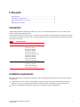
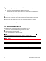
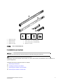
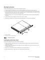
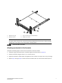
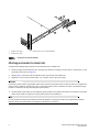
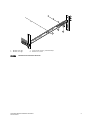
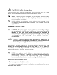
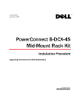
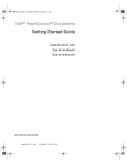
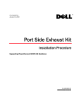
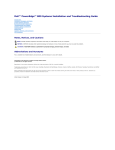
53-1001792-01
January 31, 2010
Fixed Rack Mount Kit
Installation Procedure
Supporting PowerConnect B-200E, 300, 4100, 4900, 5000, 5100, 5300,
7500 series, 7600, 7800, 8000, AP7420, Encryption Switch, and VA-40FC
53-1001792-01
*53-1001792-01*
Notes, Cautions, and Warnings
NOTE
A NOTE indicates important information that helps you make better use of your computer.
CAUTION
See the safety and regulatory information that shipped with your system. For additional regulatory
information, see the Regulatory Compliance Homepage on www.dell.com at the following location:
www.dell.com/regulatory_compliance.
CAUTION
A CAUTION indicates potential damage to hardware or loss of data if instructions are not followed.
DANGER
A DANGER indicates a potential for property damage, personal injury, or death.
____________________
Information in this document is subject to change without notice.
© 2009 Dell Inc. All rights reserved.
Reproduction of these materials in any manner whatsoever without the written permission of Dell Inc. is strictly forbidden.
Trademarks used in this text: Dell, the DELL logo, Inspiron, Dell Precision, Dimension, OptiPlex, Latitude, PowerEdge, PowerVault, PowerApp, Dell
OpenManage and the YOURS IS HERE logo are trademarks of Dell Inc.; Intel, Pentium, and Celeron are registered trademarks of Intel Corporation
in the U.S. and other countries; Microsoft, Windows, Windows Server, MS-DOS and Windows Vista are either trademarks or registered trademarks
of Microsoft Corporation in the United States and/or other countries.
Other trademarks and trade names may be used in this document to refer to either the entities claiming the marks and names or their products.
Dell Inc. disclaims any proprietary interest in trademarks and trade names other than its own.
Regulatory Model Codes: Brocade DCX-4S, Brocade DCX
2
Fixed Rack Mount Kit Installation Procedure
53-1001792-01
In this guide
• Introduction. . . . . . . . . . . . . . . . . . . . . . . . . . . . . . . . . . . . . . . . . . . . . . . . . . . .
• Installation requirements. . . . . . . . . . . . . . . . . . . . . . . . . . . . . . . . . . . . . . . . .
• Tool requirements and parts list . . . . . . . . . . . . . . . . . . . . . . . . . . . . . . . . . . .
• Installation procedure . . . . . . . . . . . . . . . . . . . . . . . . . . . . . . . . . . . . . . . . . . .
3
3
4
5
Introduction
This document provides instructions to install a 1U, 1.5U, or 2U switch (or SAN Router) in a 19-in. (48.3 cm) EIA
cabinet using the Fixed Rack Mount Kit.
The supported switches are listed in Table 1. The switch can be installed so that the port side is either flush with the
front rails or recessed from the front rails. A recessed position allows a more gradual bend in the fiber optic cables
connected to the switch.
TABLE 1
Supported switches
Switch Height
Switch Model
1U
PowerConnect B-200E
PowerConnect B-300
PowerConnect B-4100
PowerConnect B-5000
PowerConnect B-5100
PowerConnect B-7500 series
PowerConnect B-7600
PowerConnect B-7800
PowerConnect B-8000
PowerConnect B-VA-40FC
2U
PowerConnect B-4900
PowerConnect B-5300
PowerConnect B-AP7420
Brocade Encryption Switch
Installation requirements
Allow 15 to 30 minutes to complete this procedure. Note the following requirements to ensure correct installation
and operation:
• Provide space in a 19-in. (48.3 cm) EIA cabinet, as required for the switch type, with a minimum distance of
28.25 in. (71.76 cm) and a maximum distance of 29.88 in. (75.90 cm) between the front and back rails.
• Verify that the additional weight of the switch does not exceed the cabinet’s weight limits.
Fixed Rack Mount Kit Installation Procedure
53-1001792-01
3
• Ensure that an electrical branch circuit with the following characteristics is available:
- Required voltage and frequency as indicated in the hardware reference manual. (200-230 VAC is always
preferred)
-
Protection by a circuit breaker in accordance with local electrical codes.
Supply circuit, line fusing, and wire size that conform to the electrical rating on the switch nameplate.
Grounded outlet compatible with the power cord and installed by a licensed electrician.
• Ensure that all equipment installed in the cabinet is grounded through a reliable branch circuit connection. Do
not rely on a secondary connection to a branch circuit, such as a power strip.
• Ensure that the cabinet is mechanically secured to ensure stability.
• Ensure that the air temperature at the fan inlet is less than 104o Fahrenheit (40o Celsius) during switch
operation.
• Ensure that the airflow available at the air vents meets the minimum requirements for the switch.
ATTENTION
Install the switch with the fan side facing the air-intake aisle. The chassis air intake is on the fan side and exhaust is
on the port side.
Tool requirements and parts list
The following items are required to install a switch using the fixed rack mount kit:
• Clamps or other means of temporarily supporting the switch in the cabinet.
• Phillips #2 screwdriver with torque capability.
• 1/4 in. slotted-blade screwdriver with torque capability.
ATTENTION
Use the screws specified for use with the switch. Longer screws can damage the switch.
Ensure that the items listed in Table 2 and illustrated in Figure 1 are included in the kit.
TABLE 2
Parts list
Item
Description
Quantity
1
Bracket, front right
1
2
Bracket, front left
1
3
Bracket, rear right
1
4
Bracket, rear left
1
5
Screw, 8-32 x 5/16 in., panhead Phillips (torque to 15 in.-lbs, 17 cm-kgs)
12
6
Screw, 6-32 x 1/4 in., flathead Phillips (torque to 9 in.-lbs, 10 cm-kgs)
8
7
Screw, 10-32 x 5/8 in., panhead Phillips (torque to 25 in.-lbs, 29 cm-kgs)
8
8
Retainer nut, 10-32
8
4
Fixed Rack Mount Kit Installation Procedure
53-1001792-01
HT
RIG
1
scale: 3/16" = 1"
2
B
EV.
2 R 05
2-0 3/20
40
02 01/0
-00 N
#2 CON
X
FO
T
LEF
3
4
5
6
(12x)
(8-32 x 5/16 in.)
1
2
3
4
Bracket, front right
Bracket, front left
Bracket, rear left
Bracket, rear right
FIGURE 1
5
6
7
8
(8x)
(6-32 x 1/4 in.)
7
(8x)
(10-32 x 5/8 in.)
8
(8x)
(10-32)
Screw, 8-32 x 5/16 in., panhead Phillips
Screw, 6-32 x 1/4 in., flathead Phillips
Screw, 10-32 x 5/8 in., panhead Phillips
Retainer nut, 10-32
Items in Fixed Rack Mount Kit
Installation procedure
ATTENTION
The switch must be turned off and disconnected from the fabric during this procedure.
NOTE
Although this document describes how to install a 1U, 1.5U, and 2U switch, the illustrations show a 1U switch as a
typical configuration.
Complete these tasks to install the switch in a cabinet:
•
•
•
•
“Attaching front brackets”
“Installing the switch in the cabinet”
“Attaching rear brackets to front brackets”
“Attaching rear brackets to cabinet rails”
Fixed Rack Mount Kit Installation Procedure
53-1001792-01
5
Attaching front brackets
Complete the following steps to attach the front brackets to the switch.
1. Position the right front bracket (Item 1) with the flat side against the right side of the switch (Figure 2).
2. Insert two 8-32 x 5/16 in. screws (Item 5) into one of the pairs of vertically aligned holes in the bracket and then
into the pair of holes on the side of the switch. To install the switch in a recessed position in the cabinet, use the
bracket holes that are set back from the end of the bracket.
3. Insert each 8-32 x 5/16 in. screw (Item 5) through the holes in the bracket and into the corresponding hole in
the switch.
4. Tighten all 8-32 x 5/16 in. screws to a torque of 15 in.-lbs (17 cm-kgs).
5. Repeat step 1 through step 5 to attach the left front bracket (Item 2) to the left side of the switch.
scale: 1/8" = 1"
HT
RIG
Sil
kW
orm
!
41
00
IO
IO
I
LN
K
SP
D
V. B
RE
-02 2005
02
24 /03/
-000 N 01
#2 ON
XC
FO
5
1
1
5
Bracket, front right
Screw, 8-32 x 5/16 in., panhead Phillips
FIGURE 2
Position the front bracket
Installing the switch in the cabinet
Complete the following steps to install the switch in the cabinet.
1. Position the switch in the cabinet (Figure 3), providing temporary support under the switch until the rail kit is
secured to the cabinet.
2. Attach the right front bracket (Item 1) to the right front rack rail using two 10-32 x 5/8 in. screws (Item 7) and
two retainer nuts (Item 8).
3. Repeat step 2 to attach the left front bracket (Item 2) to the left front rack rail.
4. Tighten all 10-32 x 5/8 in. screws (Item 7) to a torque of 25 in.-lbs (29 cm-kgs
6
Fixed Rack Mount Kit Installation Procedure
53-1001792-01
2
T
LEF
scale: 1/8" = 1"
H
RIG
T
Silk
Wor
m
!
41
00
IO
IO
I
LN
K
SP
D
V. B
RE
-02 2005
02
24 /03/
-000 N 01
#2 ON
XC
FO
1
8
7
1
2
Bracket, front right
Bracket, front left
7
8
Screw, 10-32 x 5/8 in., panhead Phillips
Retainer nut, 10-32
NOTE
The figure above is shown with a recessed mounting configuration on the left and a flush mounting
configuration on the right. You can select either mounting option.
FIGURE 3
Position the switch in the cabinet
Attaching rear brackets to front brackets
Complete the following steps to attach the rear brackets to the front brackets.
1. Position the right rear bracket (Item 4) inside the right front bracket (Item 1) (Figure 4).
2. Attach the brackets using four 6-32 x 1/4 in. screws (Item 6).
3. Adjust the brackets to cabinet depth and tighten the Item 6 screws to a torque of 9 in.-lbs (10 cm-kgs).
4. Repeat step 1 through step 3 to attach the left rear bracket (Item 3) to the left front bracket (Item 2).
Fixed Rack Mount Kit Installation Procedure
53-1001792-01
7
6
RIG
HT
4
B
EV.
2 R 05
2-0 3/20
40
02 01/0
-00 N
#2 CON
X
FO
1
4
Bracket, front right
Bracket, rear right
FIGURE 4
6
1
Screw, 6-32 x 1/4 in., flathead Phillips
Position the rear and front brackets
Attaching rear brackets to cabinet rails
Complete the following steps to attach the rear brackets to the cabinet rails.
1. Attach the right rear bracket (Item 4) to the right rear cabinet rail using two 10-32 x 5/8 in. screws (Item 7) and
two retainer nuts (Item 8) (Figure 5).
2. Repeat step 1 to attach the left rear bracket (Item 3) to the left rear cabinet rail.
3. Tighten the 10-32 x 5/8 in. screws (Item 7) to a torque of 25 in.-lbs (29 cm-kgs).
ATTENTION
Connect the power cords to a grounded outlet only. Ensure that any power cord is routed so that it is not exposed to
stress. Leave a minimum service loop of 6 in. in the power cord(s) at the connection to switch. This allows enough
freedom of movement to plug and unplug the power cord(s).
4. Provide power to the switch by connecting the power cord(s) to the power connectors on the switch and a power
outlet. Some switches require you to flip a power switch to be powered on.
NOTE
Do not connect the switch to the network until the IP address is correctly set. Refer to the appropriate hardware
reference manual for information on setting the IP address for the switch.
8
Fixed Rack Mount Kit Installation Procedure
53-1001792-01
7
RIG
HT
4
8
B
EV.
2 R 05
2-0 3/20
40
02 01/0
-00 N
#2 CON
X
FO
1
4
Bracket, front right
Bracket, rear right
FIGURE 5
7
8
1
Screw, 10-32 x 5/8 in., panhead Phillips
Retainer nut, 10-32
Attach the rear bracket to the cabinet rail
Fixed Rack Mount Kit Installation Procedure
53-1001792-01
9
10
Fixed Rack Mount Kit Installation Procedure
53-1001792-01