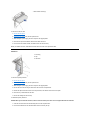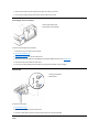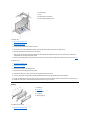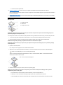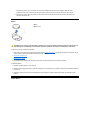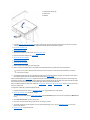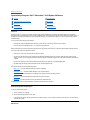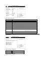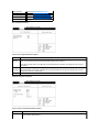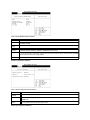
1
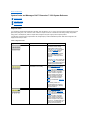
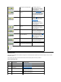
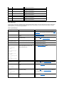
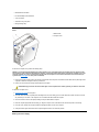
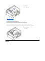
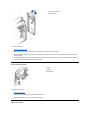
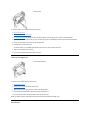
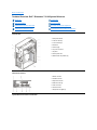
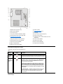
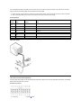
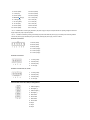
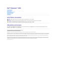
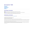
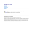
Dell™ Dimension™ 2100 System Reference
Conventions
Technical Overview
Controls and Lights
Drivers
System Codes and Messages
System Setup Program
Technical Specifications
Removing and Replacing Parts
Documentation
Model MCM
Information in this document is subject to change without notice.
© 2001-2002 Dell Computer Corporation. All rights reserved.
Reproduction in any manner whatsoever without the written permission of Dell Computer Corporation is strictly forbidden.
Trademarks used in this text: Dell and Dimension are trademarks of Dell Computer Corporation; Microsoft, Windows, and MS-DOS are registered trademarks of Microsoft
Corporation; Intel, Celeron, and Pentium are registered trademarks of Intel Corporation; VESA is a registered trademark of Video Electronics Standards Association; Adobe is
a trademark of Adobe Systems Incorporated, which may be registered in certain jurisdictions.
Other trademarks and trade names may be used in this document to refer to either the entities claiming the marks and names or their products. Dell Computer Corporation
disclaims any proprietary interest in trademarks and trade names other than its own.
August 2002 Rev. A03
Back to Contents Page
System Codes and Messages: Dell™ Dimension™ 2100 System Reference
Diagnostic Codes
POST Beep Codes
System Messages
Diagnostic Codes
Your computer is equipped with four diagnostic code lights, which are labeled "A," "B," "C," and "D" on the back of the computer. Each of the four
lights can be yellow, green, or off, as shown in Table 1. When the computer is turned on or restarted and is functioning normally, the lights flash
during power-on self-test (POST). After the computer starts, the lights remain green to signify normal computer operation.
If a malfunction is detected and the computer fails to start, the lights display a code that identifies the problem. Write down the diagnostic code
displayed and look it up in Table 1.
Table 1. Diagnostic Codes
Diagnostic Code
Definition
Corrective Action
Power up default.
Make sure that the computer is
connected to a known working
electrical outlet, and then check
whether the front-panel power light is
on or off. If the power light is off,
check the power supply. If the
problem persists, see "Contacting Dell" in the Solutions Guide for
instructions on obtaining technical
assistance.
Remove all cards. If the computer still does not start, see "Contacting Dell" in the Solutions Guide for instructions
on obtaining technical assistance.
System board is receiving power,
but the BIOS is not executing.
Set the configuration jumper to
Maintenance mode, and restart the
computer. Enter the system setup
program and ensure that the
processor speed is set correctly. Exit
and save the setting. Turn off the
computer, reset the configuration
jumper to Normal mode, and then
restart the computer. Remove all
cards and restart the computer to
determine if a resource conflict
exists. If a conflict exists, resolve the
conflict.
If the problem persists, see "Contacting Dell" in the Solutions
Guide for instructions on obtaining
technical assistance.
Recovery mode from BIOS failure.
Set the configuration jumper to
Maintenance mode, and restart the
computer. Enter the system setup
program and ensure that the
processor speed is set correctly. Exit
and save the setting. Turn off the
computer, reset the configuration
jumper to Normal mode, and then
restart the computer. If the problem
persists, see "Contacting Dell" in the Solutions Guide for instructions on
obtaining technical assistance.
Microprocessor has failed a BIOS
test.
If the problem persists, see "Contacting Dell" in the Solutions
Guide for instructions on obtaining
technical assistance.
Memory failed to be sized or
enabled.
Reseat the memory modules. If the
problem persists, remove all but one
memory module, and then restart the
computer. Repeat this step until the
malfunctioning memory module is
identified.
PCI bus failure has occurred.
Remove all cards and restart the
computer to determine if a resource
conflict exists. If a conflict exists,
resolve the conflict. If the problem persists, see "Contacting Dell" in the Solutions
Guide for instructions on obtaining
technical assistance.
Video controller failed to initialize or
respond.
If the problem persists, see "Contacting Dell" in the Solutions
Guide for instructions on obtaining
technical assistance.
IDE bus failure has occurred.
Reseat the IDE cables. If the problem
persists, see "Contacting Dell" in the Solutions Guide for instructions on
obtaining technical assistance.
USB port or a device connected to it Disconnect the device from the USB
has failed initialization.
port. If the problem persists, see "Contacting Dell" in the Solutions
Guide for instructions on obtaining
technical assistance.
Other failure.
See "Contacting Dell" in the Solutions Guide for instructions on
obtaining technical assistance.
Computer has started and turned
No action is necessary.
over control to the operating system.
POST Beep Codes
If the monitor cannot display errors or problems, during power-on self-test (POST) the computer may emit a series of beeps, or beep code, that
identifies the problem.
If the computer emits a beep code and then fails to start, write down the beep code and look it up in Table 2.
Table 2. System Beep Codes
Beep
Code
Possible Cause
Corrective Action
1
Memory refresh failure
Reseat the memory modules. 2
Parity cannot be reset
Reseat the memory modules.
3
Memory failure within the first 64
KB of memory
Reseat the memory modules.
4
Timer not operational
See "Contacting Dell" in the Solutions Guide for instructions on
obtaining technical assistance.
5
Processor failure
See "Contacting Dell" in the Solutions Guide for instructions on
obtaining technical assistance.
6
8442 keyboard controller error
See "Contacting Dell" in the Solutions Guide for instructions on
obtaining technical assistance.
7
Processor exception error
See "Contacting Dell" in the Solutions Guide for instructions on
obtaining technical assistance.
8
Video display memory error
See "Contacting Dell" in the Solutions Guide for instructions on
obtaining technical assistance.
9
Optional ROM checksum error
See "Contacting Dell" in the Solutions Guide for instructions on
obtaining technical assistance.
10
CMOS memory error
See "Contacting Dell" in the Solutions Guide for instructions on
obtaining technical assistance.
11
BIOS checksum error
See "Contacting Dell" in the Solutions Guide for instructions on
obtaining technical assistance.
System Messages
The first column in Table 3 lists (in alphabetical order) system messages that may appear on the screen during the boot routine or during normal
computer operation. The second column in the table lists probable causes of the messages, and the third column either provides a corrective
action or refers you to a source for resolving the problem.
Table 3. System Messages
Message
Possible Cause
Corrective Action
8042 Gate-A20 Error
The keyboard controller failed its test.
If you receive this message after making changes in the system
setup program, enter the program and restore the original value
(s).
Address Line Short!
Error in the address decoding circuitry in the
memory.
Reseat the memory modules.
C: Drive Error
The hard drive is not working or is not
configured correctly.
Ensure that the drive is installed correctly in the chassis and
defined correctly in the system setup program.
Cache Memory Bad, Do
Not Enable Cache
Cache memory is not operating.
See "Contacting Dell" in the Solutions Guide for instructions
on obtaining technical assistance.
Ch-2 Timer Error
System board timer error occurred.
See "Contacting Dell" in the Solutions Guide for instructions
on obtaining technical assistance.
CMOS Battery State
Low
The system configuration information in the
system setup program is incorrect, or the
battery charge may be low.
Enter the system setup program and verify the system
configuration; then restart the computer.
Diskette Boot
Failure
Drive A or B is present but has failed the BIOS
POST.
Ensure that the drive is installed correctly in the computer frame
and defined correctly in the system setup program. Check the
interface cable at both ends.
DMA Error
Error in the DMA controller on the system
board.
The keyboard or system board may need to be replaced.
C: Drive Failure
CMOS Checksum
Failure
CMOS Display Type
Mismatch
CMOS Memory Size
Mismatch
CMOS System Options
Not Set
CMOS Time and Date
Not Set
DMA 1 Error
DMA 2 Error
FDD Controller
Failure
BIOS cannot communicate with the floppy drive Ensure that the drive is installed correctly in the computer frame
or hard drive controller.
and defined correctly in the system setup program. Check the
interface cable at both ends.
HDD Controller
Failure
INTR1 Error
INTR2 Error
Interrupt channel on the system board failed the The keyboard or system board may need to be replaced.
POST.
Invalid Boot
Diskette
The operating system cannot be located on
drive A or drive C.
KB/Interface Error
An error occurred with the keyboard connector. The keyboard or system board may need to be replaced.
Keyboard Error nn
The BIOS has detected a stuck key
represented by scan code nn.
Make sure that nothing is resting on the keyboard; if a key
appears to be stuck, carefully pry it up. If the problem persists,
you may need to replace the keyboard.
No ROM Basic
The operating system cannot be located on
drive A or drive C.
Enter the system setup program and confirm that drive A or
drive C is properly identified.
Back to Contents Page
Enter the system setup program and confirm that drive A or
drive C is properly identified.
Back to Contents Page
Resolving Software and Hardware Incompatibilities: Dell™ Dimension™ 2100 System Reference
Windows 98 and Windows Millennium Edition (Me) Hardware and Software Incompatibility Occurrences
Windows 2000 Hardware and Software Incompatibility Occurrences
Windows® 98 and Windows Me Hardware and Software Incompatibility Occurrences
Interrupt request (IRQ) conflicts occur on computers running the Microsoft® Windows 98 or Windows Me operating system if a device is either:
l
Not detected during the Windows 98 or Windows Me Plug and Play setup
l
Detected but incorrectly configured
To check for conflicts on a computer running Windows 98 or Windows Me:
1. Click the Start button, point to Settings, and click Control Panel.
2. In the Control Panel, double-click System.
3. Click the Device Manager tab.
4. In the Device Manager list, check for conflicts with the other devices.
Conflicts are indicated by a yellow exclamation point (!) beside the conflicting device or a red X if the device has been disabled.
5. Double-click any conflicting device listed to bring up the Properties window so you can determine what needs to be reconfigured or
removed from the Device Manager.
Resolve these conflicts before checking specific devices.
6. Double-click the malfunctioning device type in the Device Manager list.
7. Double-click the icon for the specific device in the expanded list.
The Properties window appears.
8. Resolve any IRQ conflicts.
If there is an IRQ conflict, the Device status area in the Properties window reports what cards or devices are sharing the device's IRQ.
You can also use the Windows 98 or Windows Me Hardware Conflict Troubleshooter. To use the troubleshooter:
1. Click the Start button, and then click Help.
2. In Windows 98, double-click Troubleshooting on the Contents tab, and then double-click If you have a hardware conflict.
In Windows Me, double-click Troubleshooting in the What would you like help with? list, click Hardware & system device
problems, click Hardware, memory, & others, and then click Hardware Troubleshooter.
Windows 2000 Hardware and Software Incompatibility Occurrences
To check for conflicts on a computer running the Microsoft Windows 2000 operating system:
1. Click the Start button, point to Settings, and click Control Panel.
2. In the Control Panel, double-click System.
3. Click the Hardware tab.
4. Click Device Manager.
5. Click View, and then click Resources by connection.
6. Double-click Interrupt request (IRQ) to view the IRQ assignments.
Conflicts are indicated by a yellow exclamation point (!) beside the conflicting device or a red X if the device has been disabled.
7. Double-click any conflicting device listed to bring up the Properties window so you can determine what needs to be reconfigured or
removed from the Device Manager.
Resolve these conflicts before checking specific devices.
8. Double-click the malfunctioning device type in the Device Manager list.
9. Double-click the icon for the specific device in the expanded list.
The Properties window appears.
If there is an IRQ conflict, the Device status area in the Properties window reports what cards or devices are sharing the device's IRQ.
10. Resolve the IRQ conflicts.
You can also use the Windows 2000 Hardware Conflict Troubleshooter. To use the troubleshooter:
1. Click the Start button, and then click Help.
2. Double-click Troubleshooting and Maintenance on the Contents tab.
3. Double-click If you have a hardware conflict.
Back to Contents Page
Back to Contents Page
Controls and Lights: Dell™ Dimension™ 2100 System Reference
Front Panel
Back Panel
Front Panel
1 Floppy-drive access light — Lights up when a floppy drive is being accessed.
2 Power — Turns the computer on and off. Lights up when the computer is on. Press and hold
for 4 seconds to shut down.
3 Hard-drive access light — Lights up when a hard drive is being accessed.
Back Panel
1 Voltage selection switch — Selects the operating voltage for the computer.
2 Diagnostic code lights (4) — If a malfunction is detected and the computer fails to start, the
lights display a code that identifies the problem.
Back to Contents Page
Back to Contents Page
Conventions: Dell™ Dimension™ 2100 System Reference
Notes, Notices, and Cautions
Typographical Conventions
The following subsections describe notational conventions used in this document.
Notes, Notices, and Cautions
Throughout this guide, blocks of text may be accompanied by an icon and printed in bold type or in italic type. These blocks are notes, notices, and
cautions, and they are used as follows:
NOTE: A NOTE indicates important information that helps you make better use of your computer.
NOTICE: A NOTICE indicates either potential damage to hardware or loss of data and tells you how to avoid the problem.
CAUTION: A CAUTION indicates a potential for property damage, personal injury, or death.
Typographical Conventions
The following list defines (where appropriate) and illustrates typographical conventions used as visual cues for specific elements of text throughout
this document:
l
Interface components are window titles, button and icon names, menu names and selections, and other options that appear on the monitor
screen or display. They are presented in bold.
Example: Click OK.
l
Keycaps are labels that appear on the keys on a keyboard. They are enclosed in angle brackets.
Example: <Enter>
l
Key combinations are series of keys to be pressed simultaneously (unless otherwise indicated) to perform a single function.
Example: <Ctrl><Alt><Enter>
l
Commands presented in lowercase bold are for reference purposes only and are not intended to be typed when referenced.
Example: “Use the format command to . . . .”
In contrast, commands presented in the Courier New font are part of an instruction and intended to be typed.
Example: “Type format a: to format the floppy in drive A.”
l
Filenames and directory names are presented in lowercase bold.
Examples: autoexec.bat and c:\windows
l
Screen text is a message or text that you are instructed to type as part of a command (referred to as a command line). Screen text is
presented in the Courier New font.
Example: The following message appears on your screen:
No boot device available
Example: “Type md c:\programs and press <Enter>.”
l
Variables are placeholders for which you substitute a value. They are presented in italics.
Example: DIMM_x (where x represents the memory socket designation).
Back to Contents Page
Back to Contents Page
Documentation: Dell™ Dimension™ 2100 System Reference
Printed Documentation
Online Documentation
Printed Documentation
The following printed documents are provided to you with your purchase of your computer. They are located inside the documentation box that
came with your computer. For your convenience, you may also view these documents online. Be sure to read the following instructions thoroughly
before viewing the documents.
You must right-click the link for a portable document format (PDF) file and save the file to your hard drive. Attempting to open
large PDF files through your browser by left-clicking the link causes your computer to freeze.
To save PDF files (files with an extension of .pdf) to your hard drive, right-click the document title, click Save Target As in Microsoft® Internet
Explorer or Save Link As in Netscape Navigator, and specify a location on your hard drive.
Right-click only the following links:
l
Dell Dimension 2100 Solutions Guide (.pdf) (1601 KB) — Provides information on adding upgrades, performing basic troubleshooting
procedures, and reinstalling drivers. It also covers technical specifications.
NOTES: PDF files require Adobe™ Acrobat Reader, which can be downloaded from the Adobe World Wide Web site at http://www.adobe.com/acrobat/.
To view a PDF file, launch Acrobat Reader. Click File–> Open and select the PDF file.
Online Documentation
The Tell Me How help file is already loaded on your hard drive when you receive your computer. To open the file, click the Start button on the
Windows® desktop, point to Programs—> User’s Guides, and then click Tell Me How.
Tell Me How help files (files with an extension of .chm) require Microsoft Internet Explorer 4.0 or later.
The Tell Me How help file allows you to search for information in multiple ways. You can quickly link to information on the following topics:
l
Hardware and software features of your computer
l
The Windows desktop, where you can change your wallpaper and screen saver, create shortcuts, and position icons
l
Software access, installation, and removal
l
Basic file management, such as finding, copying, deleting, and renaming files
l
Tips on using your computer hardware
To Download a New Tell Me How Help File and Associated Files
1. Right-click the following link to the hhactivex.dll file: hhactivex.dll.
2. Click Save Target As in Microsoft Internet Explorer or Save Link As in Netscape Navigator, and specify c:\windows\system on your hard
drive.
3. Click the Start button on the Microsoft Windows desktop, and then click Run.
4. Type regsvr32 hhactivex.dll and then press <Enter>.
5. Click OK when the installation is complete.
6. Right-click the following link to the file: Dell Dimension 2100 System Tell Me How (.chm) (2385 KB).
7. Click Save Target As in Microsoft Internet Explorer or Save Link As in Netscape Navigator, and specify a location on your hard drive.
Viewing the Tell Me How Help File
1. Click the Start button on the Windows desktop, point to Programs, and then click Windows Explorer.
2. Navigate to the directory in which you saved the Tell Me How help file.
3. Double-click the file (tellhow.chm).
Back to Contents Page
Back to Contents Page
Drivers: Dell™ Dimension™ 2100 System Reference
Your Computer's Drivers
Using the Dell Dimension ResourceCD to Reinstall Drivers
All of your computer’s drivers for Dell-installed devices are operative when you receive the computer—no further installation or configuration is
needed. However, if you ever need to reinstall any of these drivers, the driver files are provided on the Dell Dimension ResourceCD.
Device problems can often be corrected by reinstalling the appropriate drivers. Also, hardware manufacturers frequently provide updated drivers
that support feature enhancements or that correct problems. Obtain updated drivers for products purchased from Dell at the support section of the
Dell World Wide Web site (http://support.dell.com).
NOTICE: Drivers available on the Dell Web site have been validated for correct operation on Dell systems. Installing drivers obtained
from other sources may cause errors or performance degradation.
Your Computer’s Drivers
The device drivers that can be reinstalled on your computer are listed below:
l
Intel® 800 Series Chip Set Driver — Installs Microsoft® Windows® 98 device installation files (.inf) that tell the operating system how
certain chip set components should be configured for proper operation.
l
Intel Security Driver — Provides a heightened level of security for transmitting data across a network or across the Internet.
l
Intel 810e Video Driver — Enables the computer’s video controller to properly function.
l
Other Drivers — Control the devices, such as video, modem, or network interface controller (NIC) cards, that might be installed on your
computer. For instructions on how to reinstall those drivers, see the device’s documentation. The documentation can be found by clicking the
Start button on the Windows desktop, pointing to Programs—> User’s Guides, and then clicking System Documentation.
NOTES: If a driver does not appear under a selected operating system on the Dell Dimension ResourceCD, then the driver is not
required by that operating system.
If you reinstall Windows 98, you must reinstall the Intel 800 Series Chip Set driver before you reinstall any other drivers.
Using the Dell Dimension ResourceCD to Reinstall Drivers
NOTICE: The Dell Dimension ResourceCD contains drivers for devices that might not be installed in your computer. Do not install
device drivers unless you first identify the specific driver intended for the hardware installed in your computer (see "Your
Computer’s Drivers"). Installing incorrect drivers might make your computer inoperable.
1. From the Windows desktop, insert the Dell Dimension ResourceCD into the CD or DVD drive.
If this is your first time to use the ResourceCD, go to the next step. If not, go to step 5.
2. When the ResourceCD Installation program starts, follow the instructions on the screen.
3. When the InstallShield Wizard Complete window appears, remove the ResourceCD and click Finish to restart the computer.
4. When you see the Windows desktop, reinsert the ResourceCD into the CD or DVD drive.
5. At the Welcome Dell System Owner screen, click Next.
The Please wait... the ResourceCD is detecting hardware in your computer message appears.
The drivers that are used by your computer are automatically displayed in the My Drivers—The ResourceCD has identified these
components in your system window.
6. Click the driver that you want to reinstall and follow the prompts on the screen.
If a particular driver is not listed, then that driver is not required by your operating system.
NOTE: The ResourceCD displays drivers only for hardware that Dell installed at the time of purchase. If you installed any additional
hardware, those drivers may not be displayed by the ResourceCD. If those drivers are not displayed, exit the ResourceCD program and
refer to the documentation and drivers that came with that product.
To view other contents on the ResourceCD:
1. Be sure your computer is selected in the System Model list.
2. Be sure your operating system is selected in the Operating System list.
3. Select the type of device in the Device Type list.
NOTICE: The Dell Dimension ResourceCD contains drivers for devices that are not part of your computer. Only reinstall the specific
drivers for hardware included in your computer. Otherwise, your computer might not work correctly.
4. Select a topic in the Topic list.
If you select Drivers in the Topic list and a particular driver is not listed, then that driver is not required by your operating system.
Back to Contents Page
Back to Contents Page
Removing and Replacing Parts: Dell™ Dimension™ 2100 System Reference
Overview
Hard Drive
Precautionary Measures
Power Supply and Fan Assembly
Recommended Tools
Control Panel
Cover
Cards
Rotating the Power Supply
Memory
Front panel
Heat Sink
3.5-Inch Front Panel Insert
Microprocessor
Upper 3.5-Inch Drive
Battery
Lower 3.5-Inch Floppy Drive
System Board
5.25-Inch Drive
Overview
Unless otherwise noted, each of the following procedures assumes:
l
You have the recommended tools.
l
You have performed the steps in "Precautionary Measures."
l
You have removed the computer cover.
l
You can replace or reinstall a part by performing the removal procedure in reverse order.
Precautionary Measures
Before you remove or replace parts in the computer, read the following caution for your personal safety and to prevent damage to the computer
from electrostatic discharge (ESD).
CAUTION FOR YOUR PERSONAL SAFETY AND PROTECTION OF THE EQUIPMENT.
Before you start to work on the system, perform the following steps in the sequence listed:
1. Turn off your computer and all devices.
2. Ground yourself by touching an unpainted metal surface at the back of the computer before touching anything inside
your computer.
While you work, periodically touch an unpainted metal surface on the computer to dissipate any static electricity that
might harm internal components.
3. Disconnect any devices connected to the computer, including the monitor, from their electrical outlets to reduce the
potential for personal injury or shock. Also, disconnect any telephone or telecommunication lines from the computer.
4. Disconnect the power cable to your computer, and then press the power button to ground the system board.
After you remove or replace parts in the computer, observe the following notice to prevent damage to the computer:
NOTICE: Make sure that all other computer cables are connected before connecting the computer to its electrical outlet.
Recommended Tools
l
Small flat-blade screwdriver
l
Wide flat-blade screwdriver
l
#1 and #2 Phillips-head screwdrivers
l
1/4-inch nut driver
l
Tweezers or long-nose pliers
l
Wrist grounding strap
Cover
1 Release latch
2 Computer cover
To remove the computer cover, perform the following steps.
NOTICE: To avoid inadvertently damaging the system board, be sure you that disconnect the computer from the electrical outlet,
disconnect the power cable from the back of the computer, and press the power button before removing the computer cover. This
computer continues to receive a small amount of power when the computer is turned off and attached to an electrical outlet (the
system-board power light is on when power is detected).
1. Face the front of the computer. Place your left hand on the left side of the computer. Push back the release latch at the top back edge of the
computer to release the computer cover into your left hand.
2. Lift the cover out from the curved hinge at the bottom of the computer.
CAUTION: Keep your hands clear of the metal edges on the computer frame and fan guard as you slide the cover back.
To replace the computer cover:
1. Rotate the power supply back into place.
2. Check all cable connections, especially those that might have come loose during your work. Fold cables and unused connectors out of the
way so that they do not catch on the computer cover or interfere with airflow inside the computer.
3. Check to see that no tools or extra parts (including screws) are left inside the computer.
4. Place the computer upright with the front facing you. Align the computer cover so its bottom hooks fit in the computer’s curved hinge.
5. Lift up the cover, making sure to keep the bottom hooks aligned with the curves in the computer.
6. Gently squeeze the right and left sides of the computer together until the cover clicks into position.
Rotating the Power Supply
1 Release latch
2 Power supply
3 Drive power cables
1. Remove the computer cover.
2. Lay the computer on its side.
3. Press the release latch while lifting the power supply. 4. Rotate the power supply out of the computer while keeping the drive power cables clear.
5. When you rotate the power supply back into the computer, gently lift the and hold the drive cables out of the way.
6. Rotate the power supply into position until its release latch clicks. Lay the drive power cables along the top of the latch.
1 Drive power cables
2 Power supply
Front Panel
1 Front-panel release tab
2 Retaining hooks
To remove the front panel:
1. Remove the computer cover.
2. While facing the front of the computer, press in the front-panel release tab the top of the computer.
3. Swing the front panel away from the computer, disengage the two retaining hooks at the bottom of the front panel, and carefully pull it away
from the computer.
4. To replace the front panel, fit the two front-panel retaining hooks into their corresponding slots on the computer frame. Rotate the front panel
toward the computer until the front panel latches into position.
3.5-Inch Front Panel Insert
1 Insert
2 Tabs (2)
3 Release tab
To remove a 3.5-inch insert:
1. Remove the front panel.
2. From the back of the front panel, press the release tab to the side.
3. Rotate the insert toward you, and remove it from the front panel.
Upper 3.5-Inch Drive
1 Drive bay plate
To remove the upper 3.5-inch drive plate and install a new drive:
1. Remove the front panel.
2. Remove the 3.5-inch front panel insert.
3. Rotate the power supply away from the system board. While holding the power supply, place the computer in the upright position.
4. Remove the metal plate covering the bay by using a screwdriver to pop out the metal plate from the left or right side of the computer frame.
5. Remove the extra rails from the inside front of the computer frame.
6. Install the rails on the sides of the drive.
The rails are marked “L” for installation on the left side of the drive and “R” for the right side of the drive.
7. Slide the drive assembly into the drive bay.
8. Connect a power supply cable and drive cables to the drive.
Lower 3.5-Inch Floppy Drive
1 Drive-release rail tabs (2)
To remove the 3.5-inch floppy drive from the lower bay:
1. Remove the front panel.
2. Rotate the power supply away from the system board.
3. While holding the power supply, place the computer in the upright position.
4. Disconnect the power and interface cables from the back of the floppy drive.
5. Press the two drive-release rail tabs, and slide the drive out of the drive bay.
Before you install the new drive, install the drive-release rails on the sides of the replacement floppy drive.
5.25-Inch Drive
1 Drive-release rail tabs (2)
To remove the 5.25-inch drive:
1. Remove the front panel.
2. Rotate the power supply away from the system board.
3. While holding the power supply, place the computer in the upright position.
4. Disconnect the power and interface cables from the back of the drive.
5. Press the two drive-release rail tabs, and slide the drive out of the drive bay.
Before you install the new drive, install the drive-release rails on the sides of the replacement drive.
Hard Drive
1 Screws (2)
2 Clip
3 Hard drive
To remove the primary hard drive:
1. Remove the front panel.
2. Rotate the power supply away from the system board.
3. While holding the power supply, place the computer in the upright position.
4. Remove the two screws securing the hard drive to the front of the computer frame.
5. Release the clip that secures the drive to the computer frame, and rotate the drive out of the computer.
6. Disconnect any cables attached to the drive.
7. Remove the existing drive from the bay.
To reinstall the primary hard drive.
NOTICE: When you reinstall the hard drive, make sure that the control panel wires are not caught underneath the hard drive.
1. Orient the new drive with its circuit board facing the front of the computer frame.
2. Press the drive between the two brackets until the drive is secured by the clip.
3. Secure the drive to the front of the computer frame with the two screws you removed.
4. Connect a power supply cable and the hard drive interface cable to the new drive.
Power Supply and Fan Assembly
1 Power-supply retaining clips
2 Power supply and fan assembly
To remove the power supply and fan assembly:
1. Disconnect the AC power cable from the computer.
2. Remove the computer cover.
3. Rotate the power supply away from the system board.
4. Disconnect the DC power cables from the POWER and OPTIONAL POWER connectors on the system board.
5. Disconnect the DC power cables from all the drives.
6. Press the power-supply retaining clips and lift the power supply and fan assembly out of the computer.
Control Panel
1 Control panel assembly
2 Mounting tabs
To remove the control panel:
1. Remove the front cover.
2. Disconnect the control panel from the system board.
3. Press the mounting tabs to release the control panel and remove the control panel assembly.
Cards
1 Card connector
2 Card
3 System-board card connector
4 Card mounting bracket and screw
To install a card:
1. Remove the computer cover.
2. Rotate the power supply.
3. Choose a system-board card connector for the card.
4. Unscrew and remove the metal filler bracket that covers the card-slot opening for the card slot you intend to use.
5. Insert the card firmly into the system-board card connector.
Align the cutout on the bottom of the card connector with the crossbar in the system-board card connector. Gently rock the card into the
system-board card connector until it is fully seated.
6. When the card is firmly seated in the system-board card connector, secure the card-mounting bracket with the screw you removed in step 4.
To remove a card:
1. Remove the computer cover.
2. Rotate the power supply.
3. Disconnect any cables connected to the card.
4. Remove the screw from the card-mounting bracket.
5. Grasp the card by its top corners, and ease it out of its system-board card connector.
6. If you are removing the card permanently, install a metal filler bracket over the empty card-slot opening in the computer.
NOTE: Installing filler brackets over empty card-slot openings is necessary to maintain Federal Communications Commission (FCC)
certification of the system. The brackets also keep dust and dirt out of your computer.
Memory
1 Cutouts (2)
2 Connector
3 Memory module
4 Notches (2)
5 Securing clips (2)
To install a memory module:
1. Remove the computer cover.
2. Rotate the power supply.
3. If necessary, remove a memory module:
a. Press out the securing clip at each end of the memory connector.
b. Grasp the module and pull up.
c. If the module is difficult to remove, gently ease the module back and forth to remove it from the connector.
4. To insert a module, press out the securing clip at each end of the memory connector.
5. Align the notches on the bottom of the module with the crossbars in the connector.
NOTICE: To avoid breaking the memory module, do not press near the middle of the module.
6. Insert the module straight down into the connector, making sure that it fits into the vertical guides at each end of the connector.
Press firmly on the ends of the module until it snaps into place.
If you insert the module correctly, the securing clips snap into the cutouts at each end of the module.
NOTE: The system memory value reported by the operating system is 1 or 2 MB less than the memory installed because that memory is reserved for video functions.
Heat Sink
1 Heat sink and fan assembly 2 Heat-sink securing clip
3 Microprocessor
4 Microprocessor socket
5 Heat-sink securing tab
The heat sink in your computer will be similar to one of those pictured in the preceding figure. To remove and replace the microprocessor and heat
sink:
1. Remove the computer cover.
2. Rotate the power supply.
3. Locate the microprocessor socket on the system board.
4. Release the metal clip that secures the heat sink and fan assembly to the microprocessor socket. Then remove the heat sink and fan
assembly from the microprocessor chip.
5. Disconnect the fan from the system board.
6. Remove and replace the microprocessor chip from the socket.
7. Unpack the heat sink and fan assembly included in your upgrade kit.
NOTICE: Ground yourself by touching an unpainted metal surface on the back of the computer.
8. Peel the release liner from the adhesive tape that is attached to the bottom of the heat sink and fan assembly.
9. Replace the heat sink and fan assembly.
NOTICE: When you install the heat sink and fan assembly, make sure that the heat sink is flat against the surface of the processor
while you are installing the clip. If the heat sink becomes tilted when you install the clip, excess heat can damage the processor.
a. Place the heat sink and fan assembly on top of the microprocessor chip.
b. Orient the securing clip and hook the shorter side of the clip over the tab on the top edge of the microprocessor socket.
c. Press down on the top to the fan to snap the clip over the tab on the bottom edge of the microprocessor socket.
d. Connect the fan to the system board.
10. Replace the computer cover, and then reconnect your computer and peripherals to their electrical outlets and turn them on.
As the computer boots, it detects the presence of the new microprocessor and automatically changes the system configuration information in
the system setup program.
11. Enter the system setup program, and confirm that the Processor Type and Processor Speed options correctly identify the newly installed
microprocessor.
Microprocessor
1 Microprocessor chip
2 Release lever
3 Microprocessor socket
NOTICE: Be careful not to bend any of the pins when you remove the microprocessor chip from its socket. Bending the pins can
permanently damage the microprocessor chip.
Your microprocessor socket is a zero insertion force (ZIF) socket with a lever-type handle that secures the chip in (or releases it from) the socket.
1. To remove the chip, pull the microprocessor-socket release lever out to unlock it and then straight up until the chip is released.
2. Remove the chip from the socket. Leave the release lever extended so that the socket is ready for the new microprocessor.
NOTICE: Ground yourself by touching an unpainted metal surface on the back of the computer.
NOTICE: Be careful not to bend any of the pins when you unpack the microprocessor. Bending the pins can permanently damage
the microprocessor.
3. Unpack the new microprocessor.
If any of the pins on the chip appear to be bent, obtain technical assistance.
4. Align the pin-1 corner of the microprocessor chip with the pin-1 corner of the microprocessor socket, as shown in the following figure.
NOTE: You must identify the pin-1 corner to correctly position the chip.
The pin-1 corner of the microprocessor is the beveled corner. The pin-1 corner of the socket, labeled "1," is the front-left corner of the
socket as you face the back of the computer.
1 Pin-1 corners of chip and socket aligned
5. Install the microprocessor chip in the socket (as shown in the preceding figure).
NOTICE: You must position the microprocessor chip correctly in the socket to avoid permanent damage to the chip and the
computer when you turn on the system.
a. If the release lever on the microprocessor socket is not all the way out, move it to that position now.
b. With the pin-1 corners of the chip and socket aligned, align the pins on the chip with the holes in the socket.
c. Set the chip lightly in the socket and make sure that all pins are headed into the correct holes. Because your system uses a ZIF
microprocessor socket, you do not need to use force, which could bend the pins if the chip is misaligned. When the chip is
positioned correctly, press it with minimal pressure to seat the microprocessor in the socket. Be careful not to bend the pins.
d. When the chip is fully seated in the socket, pivot the microprocessor-socket release lever back toward the socket until it snaps
into place, securing the chip.
Battery
1 Battery
2 Battery socket
CAUTION: There is a danger of the new battery exploding if it is incorrectly installed. Replace the battery only with the same or
equivalent type recommended by the manufacturer. Discard used batteries according to the manufacturer's instructions.
To remove the 3-volt (V), CR2032 coin-cell battery:
1. Make a copy of the screens in the system setup program. Enter the system setup program, and print (by pressing the <Print Screen> key) or
copy the system configuration information from the system setup screens.
2. Remove the computer cover.
3. Rotate the power supply.
4. Pry the battery out of its socket with your fingers or with a blunt, nonconductive object such as a plastic screwdriver.
To replace the battery:
1. Install the new battery with the "+" side facing up.
2. Rotate the power supply back into place, replace the computer cover, and reconnect your computer and devices to their electrical outlets and
turn them on.
3. Reboot the computer, press <Del> when the blue Dell logo screen appears to enter the system setup program, and restore the correct
settings.
System Board
1 System-board retaining clip
2 System board
3 Standoffs
1. If possible, enter the system setup program and print the system setup screens by pressing the <Print Screen> key before you turn off the
computer because you will have to restore the configuration information after the system board is replaced.
2. Remove the computer cover.
3. Remove the power supply.
4. Disconnect any cables connected to cards, and remove these cards.
5. Disconnect all internal cables from the system board.
6. Remove the heat sink assembly.
7. Remove the microprocessor.
8. Remove the memory modules.
9. Push the system-board retaining clip until it disengages.
10. Slide the system board forward until is no longer held by the standoffs that secure the system board to the computer frame.
NOTE: You may need to slide the board toward the front of the computer to clear the hooked standoffs before you can lift the
board from the computer.
11. Carefully lift the system board out of the input/output (I/O) gasket and remove the board from the computer. The I/O gasket is on the back of
the computer where all of the input and output ports are located (see the system board).
When you install a replacement system board, angle the back of the board downward and carefully align the connectors on the back edge of the
board with the cutouts in the I/O gasket. When properly aligned, the board connectors slide into the I/O gasket as you lower the board into position
in the chassis and reseat it on the standoffs. Lock the board in place with the system-board retaining clip.
After you install the replacement system board, replace the microprocessor, the heat sink, the memory modules, and the cards that you removed
from the old system board.
To configure the system after you install a replacement board: 1. Install the jumper plug on pins 2 and 3 of configuration jumper J7A1 to select Maintenance mode operation.
2. Replace the computer cover, and start the computer.
The computer automatically starts the system setup program, adds the Maintenance option to the menu bar, and displays the Maintenance
screen.
3. Select Clear All Passwords, and press <Enter> twice.
4. Press <F10> to exit the system setup program and save any changes you made.
5. Turn off the computer, remove the computer cover, and replace the jumper plug on pins 1 and 2 of configuration jumper J7A1 to select
Normal mode operation.
6. Replace the cover, and start the computer.
7. Re-enter the system setup program, and reset the system configuration information.
Back to Contents Page
Back to Contents Page
Technical Specifications: Dell™ Dimension™ 2100 System Reference
Microprocessor
Power
System Information
Physical
Expansion Bus
Environmental
Memory
Regulatory Notices
Drives
IRQ Assignments
Ports
Default Dell-Installed Card Placement
Video
Microprocessor
Microprocessor type
Intel® Pentium® III processor
933 MHz or 1.00 GHz internally and 133 MHz externally or 1.10 GHz internally and 100 MHz externally
NOTE: Microprocessor offerings vary by country.
Intel Celeron® processor
700, 800, or 900 MHz internally and 100 MHz externally or 1.00 or 1.10 GHz internally and
100 MHz externally
NOTE: Microprocessor offerings vary by country.
L1 cache
32-KB instruction and data cache
L2 cache
Pentium III processor
256-KB Advanced Transfer Cache that resides in the processor's core. The L2 cache runs at
the processor's internal clock speed.
Celeron processor
128-KB SRAM
Microprocessor mounting
socket 370
System Information
System chip set
Intel 810e or Intel 810 chip set
Data bus width
64 bits
Address bus width
32 bits
DMA channels
two Interrupt levels
15
System BIOS chip
4 Mb (512 KB)
System clock
100 or 133 MHz (matches external processor speed)
Expansion Bus
Bus type
PCI (version 2.2)
Bus speed
33 MHz
Card connectors
supports four three-quarter-length PCI cards
Card connector size
120 pins
Card connector data width (maximum)
32 bits
Memory
Architecture
non-ECC SDRAM 168-pin modules
Memory sockets
two; gold contacts
Memory capacities
64, 128, 256, and 512 MB
Minimum memory1
64 MB for Microsoft® Windows® 98, Windows Millennium Edition (Me), and Windows 2000;
128 MB for Windows XP
Maximum memory1
512 MB
Frequency
100 MHz NOTE: Your computer may have either PC 100 or shared2 PC 133-SDRAM modules at
100 MHz installed. Do not mix these two module types in the computer. To see which
memory type is installed in your computer, inspect the label on the memory module.
Clock cycle
10 ns (supports four clocks only)
CAS latency
three
SPD revision
1.2
Buffering
unbuffered
Voltage
3.3 V
Data bus width
64 bits
BIOS address
F0000h
1
Video memory uses 1 or 2 MB of system memory (RAM). Total RAM reported is 1 or 2 MB less than RAM installed.
2 Up to 11 MB of system memory may be allocated to support DVMT Graphics.
Drives
Externally accessible
one 5.25-inch bay and two 3.5-inch bays
Internally accessible
one bay for 1-inch-high IDE hard drive
Ports
Externally accessible
Serial (DTE)
9-pin connector; 16550C-compatible
Parallel
25-hole connector (bidirectional)
Video
15-hole connector
PS/2-style keyboard
6-pin mini-DIN connector
PS/2-compatible mouse
6-pin mini-DIN connector
USB
two USB-compliant connectors
Internally accessible
Primary IDE
40-pin connector on PCI bus
Secondary IDE
40-pin connector on PCI bus
Floppy drive
34-pin connector
Video
Video controller
Intel 810e chip set with Dynamic Video Memory and 4-MB, 133-MHz display cache or Intel
810 chip set with Dynamic Video Memory
Power
DC power supply
Wattage
145 W
Heat dissipation
700 BTU (fully loaded system without monitor)
Voltage (switch selectable on back
panel)
90 to 135 V at 60 Hz;
180 to 265 V at 50 Hz;
100 V at 50 to 60 Hz for Japanese systems
Backup battery
3-V CR2032 coin cell
Physical
Height
39 cm (15.375 inches)
Width
16.8 cm (6.625 inches)
Depth
34 cm (13.375 inches)
Weight
9.9 kg (22 lb)
Environmental
Temperature
Operating
10° to 35°C (50° to 95°F)3
Storage
–40° to 65°C (–40° to 149°F) Relative humidity
20% to 80% (noncondensing)
Maximum vibration
Operating
0.25 G at 3 to 200 Hz at 1/2 octave/min
Storage
0.5 G at 3 to 200 Hz at 1/2 octave/min
Maximum shock
Operating
bottom half-sine pulse with a change in velocity of 50.8 cm/sec (20 inches/sec)
Storage
27-G faired-square wave with a velocity change of 508 cm/sec (200 inches/sec)
Altitude
3
Operating
–15.2 to 3048 m (–50 to 10,000 ft)3
Storage
–15.2 to 10,668 m (–50 to 35,000 ft)
At 35°C (95°F), the maximum operating altitude is 914 m (3000 ft).
Regulatory Notices
FCC (U.S. only)
Class B
IC Notice (Canada only)
Class B
CE Notice
Class B
VCCI Notice (Japan only)
Class B
NOM O24 Information (Mexico only)
IRQ Assignments
IRQ Line
System Resource
IRQ Line
System Resource
IRQ0
System timer
IRQ8
RTC
IRQ1
Keyboard buffer
IRQ9
Available
IRQ2
Enables IRQ8 through IRQ15 IRQ10
Available
IRQ3
Available4
IRQ11
Available
IRQ4
Serial port
IRQ12
Mouse port
IRQ5
Available
IRQ13
Math coprocessor
IRQ6
Floppy/tape drive controller
IRQ14
Primary IDE channel
IRQ7
Parallel port
IRQ15
Secondary IDE channel
4
IRQ3 is available provided that no other device in the computer (such as a modem) is using COM2 or COM4.
Default Dell-Installed Card Placement
Card Slot
Card
PCI Slot 1
Open
PCI Slot 2
Audio
PCI Slot 3
Network adapter
PCI Slot 4
Modem
Back to Contents Page
Back to Contents Page
System Setup Program: Dell™ Dimension™ 2100 System Reference
Overview
Security Screen
Entering the System Setup Program
Boot Screen
Main Screen
Exit Screen
Advanced Screen
Clearing NVRAM
Overview
Each time you turn on or restart your computer, it compares the hardware installed in the computer to the hardware listed in the configuration
information stored in nonvolatile random-access memory (NVRAM) on the system board. If the computer detects a discrepancy between the two, it
generates error messages that identify the incorrect configuration settings. The computer then prompts you to enter the system setup program to
correct the setting.
You can use the system setup program as follows:
l
To change the system configuration information after you add, change, or remove any hardware in your computer
l
To set or change user-selectable options — for example, the user password
Dell recommends that you print the system setup program screens (by pressing <Print Screen>) or write down the information for future reference.
The system setup screens are organized as follows:
l
l
At the top is a menu bar for accessing the main program screens.
The box on the left side of each screen lists options that define the installed hardware in the computer. Fields next to the options contain
settings or values. You can change those that are enclosed in brackets. Values that are grayed out contain status information reported by the
computer.
l
The box on the right side of each screen displays help information for the option with a currently highlighted field.
l
The bottom right area lists keys and their functions for the currently displayed screen.
The menu bar provides access to the following screens:
l
Main screen — Provides settings for the basic computer configuration
l
Advanced screen — Provides detailed settings for some computer features
l
Security screen — Provides indications and settings for the system password and setup password
l
Boot screen — Provides information about which device boots the computer
l
Exit screen — Provides selections for saving and loading the configurations and
In addition to these screens, options identified by a right arrow provide access to submenus.
Entering the System Setup Program
To enter the system setup program:
1. Turn on (or restart) your computer.
2. When the blue Dell logo appears, press <Del>.
If you wait too long and the operating system begins to load into memory, let the computer complete the load operation. Then shut down the
computer and try again.
Main Screen
Table 1. Main Screen Menu Options
Option
Function
BIOS Version
Displays the version of the BIOS being used.
Processor Type
Displays the type of microprocessor installed.
Processor Speed
Displays the internal speed of the microprocessor.
Cache RAM
Displays the cache random access memory.
Service Tag
Displays the service tag for the computer.
Total Memory
Displays the total computer memory.
Memory Bank 0
Displays the memory installed in memory bank 0.
Memory Bank 1
Displays the memory installed in memory bank 1.
Processor Serial Number NOTE: This option is available only on computers that have an Intel® Pentium® III microprocessor. Displays the serial number of the processor when set to Enabled. Disabled (default) turns off this feature.
System Time
Resets the time on the computer's internal clock.
System Date
Resets the date on the computer's internal calendar.
Advanced Screen
Table 2. Advanced Screen Menu Options
Option
Function
Boot Configuration
Displays the Boot Configuration submenu.
Peripheral Configuration Displays the Peripheral Configuration submenu.
IDE Configuration
Displays the IDE Configuration submenu.
Diskette Configuration
Displays the Diskette Configuration submenu.
Event Log Configuration Displays the Event Log Configuration submenu.
Video Configuration
Displays the Video Configuration submenu.
Boot Configuration Submenu
Table 3. Boot Configuration Submenu Options
Option
Function
Plug and
Play OS
Determines whether the computer is configured to support Plug and Play devices from the operating system or from the system
BIOS. Leave this option set to No so that the BIOS handles all Plug and Play operations.
NOTE: Be sure that this option is set to No before running Dell Diagnostics. Otherwise, some diagnostics may incorrectly
report failures.
Reset
Config Data
Permits resetting of the Plug and Play configuration data to default values. Yes resets the data; No (default) retains the current
Plug and Play settings. If set to Yes, configuration data reverts to default values the next time the computer boots. This option
automatically reverts back to the No setting.
Numlock
Selects the power-on state for Numlock.
Peripheral Configuration Submenu
Table 4. Peripheral Configuration Submenu Options
Option
Function
Serial port A
Configures the serial port. Set this option to Auto (default), Enabled, or Disabled. Depending on the port setting, you can
set the following additional options:
Base I/O Address If port is set to Enabled, available I/O addresses are 3F8, 3E8, 2F8, and 2E8.
Interrupt
Parallel port
If port is set to Enabled, available interrupts are IRQ3 and IRQ4.
Configures the parallel port. Set this option to Auto (default), Enabled, or Disabled. Depending on the port setting, you can
set the following additional options:
Mode
If port is set to Auto or Enabled, available modes are Output Only, Bi-directional, ECP
(default), and EPP.
NOTE: Before changing this setting, refer to the device manufacturer's documentation for information on
which mode to use.
Base I/O
Address
If port is set to Enabled, available I/O addresses are 378 (default), 278, and 228.
Interrupt
If port is set to Enabled, available interrupts are 7 and 5.
Legacy USB
Support
Set to Disabled if legacy USB support is not desired. Auto (default) and Enabled allow support for legacy USB.
IRQ5
Reserved (default) indicates that the IRQ is reserved for use by legacy devices. Available indicates that a specific IRQ is
available on the computer.
IDE Configuration Submenu
Table 5. IDE Configuration Submenu Options
Option
Function
IDE
Controller
Configures the integrated primary and secondary IDE controllers and detects the types of drives attached to them. If set to
Primary, Secondary, or Both, the designated controller(s) are enabled, and the types of drives attached are displayed. If set to
either Primary or Secondary, the other controller is not enabled and the IRQ it normally uses becomes available. If set to
Disabled, the computer cannot detect any drives attached to the controllers and displays None for all four IDE drive options.
Primary IDE
Master
Identifies the first drive attached to the primary IDE interface, usually the boot hard drive. See "Primary IDE Master Submenu."
Primary IDE
Slave
Identifies the second drive attached to the primary IDE interface, usually a second hard drive. The format of this submenu is the
same as the one described in "Primary IDE Master Submenu"
Secondary
IDE Master
Identifies the first drive attached to the secondary IDE interface, if there is one. The format of this submenu is the same as the
one described in "Primary IDE Master Submenu."
Secondary
IDE Slave
Identifies the second drive attached to the secondary IDE interface, usually a CD or tape drive. The format of this submenu is the
same as the one described in "Primary IDE Master Submenu"
Primary IDE Master Submenu
Table 6. Primary IDE Master Submenu Options
Option
Function
Type
Specifies the type of hard drive. Settings for this option are User, Auto, CD-ROM, ATAPI Removable, Other ATAPI, IDE
Removable, and None.
LBA Mode
Control
Determines LBA mode control. Set to Enabled (default) unless directed to change it by a Dell technical support representative.
Multi-Sector
Transfers
Determines the number of sectors per block during multiple-sector transfers. If Type is set to User, set Multi-Sector Transfers
to 2 Sectors, 4 Sectors, 8 Sectors, 16 Sectors, or Disabled (turns off the feature).
PIO Mode
Determines the method of moving data to and from the IDE drive. Options include PIO modes 0, 1, 2, 3, and 4. The PIO modes
can improve the performance of a hard drive. (The higher the PIO number, the faster the transfer; most newer drives support PIO
4.) For the optimum transfer mode, set Type to Auto.
Ultra DMA
Sets the Ultra DMA mode for the drive. Options are Disabled (default), Mode 0, Mode 1, Mode 2, Mode 3, or Mode 4.
Diskette Configuration Submenu
Table 7. Diskette Configuration Submenu Options
Option
Function
Diskette
Controller
Configures the floppy drive interface. Options are Enabled (default) and Disabled.
Diskette A
Selects the floppy disk type from Not Installed, 360 KB 5 1/4", 1.2 MB 5 1/4", 720 KB 3 1/2", 1.44/1.25 MB 3 1/2", or
2.88 MB 3 1/2".
Diskette Write
Protect
Protects a floppy disk from being written to when set to Enabled. When this option is set to Disabled (default), the floppy
disk is not protected unless the write-protect tab is in place.
Event Log Configuration Submenu
Table 8. Event Log Configuration Submenu Options
Option
Function
Event Log
Displays the space available for the event log.
Event Log Validity
Displays the validity of the event log.
View Event Log
Press <Enter> to view the event log.
Clear All Event Logs
Clears all event logs when the computer restarts if set to Yes. Retains the event log information if set to No (default).
Event Logging
Enables or disables event logging.
Mark Events As Read Press <Enter>, and then select Yes or No to mark DMI events as either read or unread.
Video Configuration Submenu
Table 9. Video Configuration Submenu Option
Option
Function
Primary Video Adapter Selects Onboard or PCI as the active video controller when the computer boots.
Security Screen
Table 10. Security Screen Options
Option
Function
Supervisor Password Is
Indicates whether a supervisor password has been assigned.
User Password Is
Indicates whether a user password has been assigned.
Set Supervisor Password Sets and confirms a supervisor password.
Set User Password
Sets and confirms a user password.
Clear User Password
Clears the user password. Settings for this option are Yes or No (default).
Boot Screen
Table 11. Boot Screen Options
Option
Function
Quiet Boot
Enabled (default) displays the Dell logo. Disabled displays the normal POST messages.
Quick Boot
When set to Enabled, this option shortens the POST by eliminating some tests. If set to Disabled (default), all POST tests
occur.
Restore on AC/
Power Loss
Determines what state the computer enters when AC power is restored after a power loss. Settings are as follows:
l
l
l
Last State (default) — Computer returns to the state it was in when power was lost.
Stays Off — Computer stays off when power is restored; you must press the power button to restore power.
Power On — Computer starts up when power is restored.
On LAN
This option controls how the computer responds to a Wakeup On LAN event. The settings for this option are Power On or
Stays Off.
On PME
This option controls how the computer responds to a PCI power management enabled (PME) wakeup event. The settings for
this option are Power On or Stays Off (default).
1st Boot Device Determines which device the computer tries to boot from first. Use the up- or down-arrow key to highlight a device. Settings for
this option are as follows:
l
Floppy
l
ARMD FDD
l
ARMD HDD
l
IDE-HDD
l
ATAPI CD-ROM
l
SCSI*
l
Network*
l
Disabled
*Where SCSI or Network is the name of the installed device.
2nd Boot
Device
Determines which device the computer tries to boot from if it cannot boot from the device selected for 1st Boot Device.
Settings for this option are the same as those for 1st Boot Device except for NETWORK.
3rd Boot
Device
Determines which device the computer tries to boot from if it cannot boot from the devices selected for 1st Boot Device and
2nd Boot Device. Settings for this option are the same as those for 1st Boot Device except for NETWORK and SCSI.
4th Boot Device Determines which device the computer tries to boot from if it cannot boot from the devices selected for 1st Boot Device, 2nd
Boot Device, and 3rd Boot Device. Settings for this option are the same as those for 1st Boot Device except for
NETWORK and SCSI.
Exit Screen
Table 12. Exit Screen Options
Option
Function
Exit Saving
Changes
Saves any changes you have made, exits the system setup program, and restarts the computer.
Exit Discarding
Changes
Discards any changes you have made, exits the system setup program, and restarts the computer.
Load Setup
Defaults
Discards any changes you have made and reverts all options to their defaults, but does not exit the system setup program.
Load Custom
Defaults
Loads any settings saved using the Save Custom Defaults option. Press <Enter>. Then press the spacebar to select
Yes or No at the confirmation pop-up menu, and press <Enter> again.
Save Custom
Defaults
Saves any changes you have made, but does not exit the system setup program.
Discard Changes
Discards any changes you have made and reverts all options to their last saved settings, but does not exit the system
setup program.
Clearing NVRAM
To clear NVRAM for all devices and restart the computer:
1. Enter the system setup program.
2. Press the right-arrow key to move to the Advanced menu.
3. Press the down-arrow key to highlight the Boot Configuration submenu, and press <Enter>.
4. Press the down-arrow key to highlight Reset Config Data. Then change the setting to Yes (see Table 3).
5. Press <F10> to exit the program and restart the computer.
Back to Contents Page
Back to Contents Page
Technical Overview: Dell™ Dimension™ 2100 System Reference
Internal View
Power Supply
Back-Panel Features
DC Power Cables
System Board Connectors and Sockets
DC Power Connector Pin Assignments
System Board Configuration Jumper
Control Panel Connector (J9F2) Pin Assignments
Internal View
1 Front-panel release
2 5.25-inch drive bay
3 3.5-inch drive bays
4 Hard drive
5 Power supply
6 AC power connector
7 I/O panel
8 Security cable slot
9 Release latch and padlock ring
Back-Panel Features
1 Mouse connector
2 Parallel connector
3 Keyboard connector
4 USB connectors (2)
5 Video connector
6 Serial connector
7 Diagnostic code lights (4)
System Board Connectors and Sockets
1 Microprocessor connector (J5H1)
12 Speaker (LS9A1)
2 Memory sockets (BANKn)
13 Configuration jumper (J7A1)
3 Fan connector (J3J1)
14 Power light
4 3.3-V power connector (OPTIONAL POWER)
15 Card connectors (natural color) (PCIn)
5 Secondary IDE channel connector (SEC IDE)
16 Serial connector (COM1)
6 Control panel connector (J9F2)
17 Parallel connector; sometimes referred to as LPT1
(PARALLEL)
7 Floppy drive interface connector (FLOPPY)
18 Video connector (VIDEO)
8 Primary IDE channel connector (PRI IDE)
19 USB connectors (USBn)
9 Power input connector (POWER)
20 Mouse connector (MOUSE)
10 Battery socket (BATTERY)
21 Keyboard connector (KEYBD)
11 Wakeup On LAN connector (WOL)
System Board Configuration Jumper
NOTE: The red dot in the jumper denotes pin 1.
Jumper
Setting
Jumper
Description
Pins 1-2
jumpered (Normal
mode)
In Normal mode, system setup settings and installed passwords are
retained when the computer starts up. In this mode, an automatic recovery
is attempted if the BIOS detects that any of its main blocks are corrupted.
Pins 2-3
jumpered
(Maintenance
mode)
Starting the computer with the jumper set in Maintenance mode
automatically starts the system setup program, adds the Maintenance
option to the menu bar, and displays the Maintenance screen. This
screen provides the following option.
NOTICE: Entering Maintenance mode returns all settings in the
system setup program to their defaults. Dell strongly recommends
that you record or print all current settings before entering this
mode so that you can correct them when the computer is reset to
Normal mode.
Clear All Passwords — Disables a forgotten password so that you can
access the computer and assign new passwords. For the complete
password procedure, see "Clearing Forgotten Passwords" in the
Solutions Guide.
Power Supply
The 145-watt (W) power supply can operate from an AC power source of 115 volts AC (VAC) at 60 hertz (Hz) or 230 VAC at 50 Hz. The power
supply provides the DC operating voltages and currents listed in the following table.
NOTE: The power supply produces DC voltages only under its loaded condition. The DC power cable connectors must be connected to
their corresponding power input connectors on the system board or drives to measure these voltages.
DC Voltage Ranges
Maximum Output
Current
Voltage
Range
+3.3
VDC
+3.14 to +3.47 VDC 10.00 A
Notes
The combined load on the +3.3-VDC and +5-VDC outputs cannot exceed 85 W.
+5 VDC
+4.90 to +5.25 VDC 16.00 A
The combined load on the +3.3-VDC and +5-VDC outputs cannot exceed 85 W.
–5 VDC
–4.50 to –5.50 VDC 0.300 A
+12 VDC +11.40 to +12.60
VDC
4.5 A
The +12-VDC output can withstand surges of up to 11.0 A to support disk start-up
operations.
–12 VDC –10.80 to –13.20
VDC
0.300 A
+5 VSB
+4.75 to +5.25 VDC 1.2 A
The +5 volts standby (VSB) is sometimes called volts flea power (VFP).
DC Power Cables
DC Power Connector Pin Assignments
The power-supply output voltages can be measured at the back (wire side) of the DC power connectors without disconnecting them. The following
figures show the wire side of the connectors:
DC Power Connector P1
1 +5 VDC (red)
11 PSON#2 (brown)
2 Common (black)
12 Common (black)
3 +5 VDC (red)
13 Common (black)
4 Common (black)
14 Common (black)
5
15 –5 VDC (white)
PWRGOOD1
(orange)
6 +5 VFP (purple)
16 +5 VDC (red)
7 +12 VDC (yellow)
17 +5 VDC (red)
8 –12 VDC (blue)
18 +5 VDC (red)
9 Common (black)
19 Not connected
10 Common (black)
20 +5 VDC (red)
1 Pin 5 — PWRGOOD is a status signal generated by the power supply to notify the computer that the DC operating voltages are within the
ranges required for proper computer operation.
2 Pin 11 — PSON# is activated by pressing and releasing the power button while the power supply is in standby state. Activating PSON#
connects the power supply's PSON# input to ground, thereby switching the power supply to full-on condition.
DC Power Connector P2
1 Common (black)
2 Common (black)
3 Common (black)
4 +3.3 VDC (orange)
5 +3.3 VDC (orange)
6 +3.3 VDC (orange)
DC Power Connector P3
1 +12 VDC (yellow)
2 Common (black)
3 Common (black)
4 +5 VDC (red)
DC Power Connectors P4, P5, and P6
1 +12 VDC (yellow)
2 Common (black)
3 Common (black)
4 +5 VDC (red)
Control Panel Connector (J9F2) Pin Assignments
1 Hard-drive light (+)
2 Power light (+)
3 Hard-drive light (-)
4 Power light (-)
5 Reset switch
6 Power switch
7 Reset switch
8 Power switch
14 No pin
17 No pin
18 No pin
Back to Contents Page