1
Dell OpenManage
Server Administrator
Version 6.3
CIM Reference Guide
Notes
NOTE: A NOTE indicates important information that helps you make better use of
your computer.
___________________
Information in this publication is subject to change without notice.
© 2010 Dell Inc. All rights reserved.
Reproduction of these materials in any manner whatsoever without the written permission of Dell Inc.
is strictly forbidden.
Trademarks used in this text: Dell™, the DELL logo, and OpenManage™ are trademarks of Dell Inc.;
Microsoft® and Windows NT® are either trademarks or registered trademarks of Microsoft
Corporation in the United States and/or other countries; Intel®, Pentium®, Xeon®, Itanium®, i860®,
i960®, and Celeron® are registered trademarks and MMX™, i386™, i486™, SpeedStep™, and
Core™ are trademarks of Intel Corporation in the United States and/or other countries; AMD™,
AMD Athlon™, AMD Duron™, AMD-K5™, AMD-K6™, Opteron™, Sempron™, Phenom™ and
Turion™ are trademarks and AMD-K6 -2® and AMD-K6 -III® are registered trademarks of Advanced
Micro Devices, Inc. in the United States and/or other countries; Crusoe™ and Efficeon™ are
trademarks of Transmeta Corporation in the United States and/or other countries.
Other trademarks and trade names may be used in this document to refer to either the entities claiming
the marks and names or their products. Dell Inc. disclaims any proprietary interest in trademarks and trade
names other than its own.
July 2010
Contents
1
Introduction .
. . . . . . . . . . . . . . . . . . . . . . .
Server Administrator
. . . . . . . . . . . . . . . . . . .
What’s New in this Release .
. . . . . . . . . . . . . . .
9
10
. . . . . . . . . . . . . . . . . . . .
11
Parent Classes
. . . . . . . . . . . . . . . . . . .
Dell-Defined Classes
12
. . . . . . .
12
. . . . . . . . . . . . . . . .
12
Classes That Describe Relationships
Common Properties of Classes
. . . . . . . . . . . . .
Other Documents You May Need
2
9
. . . .
Documenting CIM Classes and Their Properties
Base Classes
9
12
. . . . . . . . . . . .
15
Typographical Conventions
. . . . . . . . . . . . . . .
16
CIM_PhysicalElement
. . . . . . . . . . . . . . .
17
. . . . . . . . . . . . . . . . . .
17
. . . . . . . . . . . . . . . . .
19
. . . . . . . . . . . . . . . . . . .
20
CIM_Chassis
. . . . . . . . . . . . . . . . . . . . . .
21
DELL_Chassis
. . . . . . . . . . . . . . . . . . . . . .
22
CIM_PhysicalElement
CIM_PhysicalPackage
CIM_PhysicalFrame
CIM_PhysicalComponent
. . . . . . . . . . . . . . . .
Contents
24
3
CIM_Chip
. . . . . . . . . . . . . . . . . . . . . . . .
CIM_PhysicalMemory
. . . . . . . . . . . . . . . . . .
CIM_PhysicalConnector .
CIM_Slot
3
28
. . . . . . . . . . . . . . . . . . . . . . . . .
31
. . . . . . . . . . . . . . . .
35
. . . . . . . . . . . . . . . . . .
36
. . . . . . . . . . . . . . . . . . . . . . .
37
CIM_LogicalElement
CIM_System
. . . . . . . . . . . . . . . . . .
38
. . . . . . . . . . . . . . . . . . . . . .
38
CIM_ComputerSystem
DELL_System .
CIM_LogicalDevice
. . . . . . . . . . . . . . . . . . .
39
. . . . . . . . . . . . . . . . . . . . . . . . .
40
CIM_LogicalPort .
. . . . . . . . . . . . . . . . . . . .
41
CIM_NetworkPort
. . . . . . . . . . . . . . . . . . . .
42
. . . . . . . . .
43
. . . . . . . . . . . . . . . . . . .
44
. . . . . . . . . . . . . . . . . . . . . . .
47
DELL_ManagedSystemServicesDevice
DELL_NetworkPort
CIM_Sensor
CIM_DiscreteSensor
. . . . . . . . . . . . . . . . . .
49
CIM_NumericSensor
. . . . . . . . . . . . . . . . . .
49
CIM_TemperatureSensor
4
Contents
26
. . . . . . . . . . . . . . . .
CIM_LogicalElement
CIM_FRU
24
. . . . . . . . . . . . . . . .
52
CIM_CurrentSensor
. . . . . . . . . . . . . . . . . . .
53
CIM_VoltageSensor
. . . . . . . . . . . . . . . . . . .
54
CIM_Tachometer
CIM_WatchDog
. . . . . . . . . . . . . . . . . . . .
55
. . . . . . . . . . . . . . . . . . . . .
56
CIM_CoolingDevice
CIM_Fan
. . . . . . . . . . . . . . . . . . .
57
. . . . . . . . . . . . . . . . . . . . . . . . .
58
CIM_UserDevice
. . . . . . . . . . . . . . . . . . . .
CIM_PointingDevice
CIM_Keyboard .
. . . . . . . . . . . . . . . . . .
59
. . . . . . . . . . . . . . . . . . . . .
61
. . . . . . . . . . . . . . . . . . .
62
. . . . . . . . . . . . . . . . . . . . .
64
CIM_PowerSupply
CIM_Controller
59
. . . . . . . . . . . . . . . . .
65
. . . . . . . . . . . . . . . . . .
66
. . . . . . . . . . . . . . . . . . .
67
CIM_PCIDevice
. . . . . . . . . . . . . . . . . . . . .
68
CIM_PCIBridge
. . . . . . . . . . . . . . . . . . . . .
69
CIM_Processor
. . . . . . . . . . . . . . . . . . . . .
70
CIM_ParallelController
CIM_SerialController
CIM_PCIController
. . . . . . . . . . . . . . . . . . .
80
. . . . . . . . . . . . . . . . . . . . . .
81
CIM_StorageExtent
CIM_Memory
CIM_CacheMemory
. . . . . . . . . . . . . . . . . . .
. . . . . . . . . . . . . . . . .
83
. . . . . . . . . . . . . . . . . . .
86
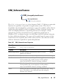
CIM_SoftwareElement
CIM_BIOSElement .
81
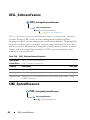
CIM_SoftwareFeature .
. . . . . . . . . . . . . . . . .
Contents
87
5
DELL_SoftwareFeature
. . . . . . . . . . . . . . . . .
88
. . . . . . . . . . . . . . . . . .
88
. . . . . . . . . . . . . . . . . . . . . . . . .
89
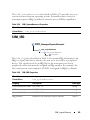
CIM_SystemResource
CIM_IRQ
. . . . . . . . . . . . . . . . .
91
. . . . . . . . . . . . . . . . . . . . . . . .
92
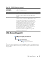
CIM_MemoryMappedIO
CIM_DMA
CIM_RedundancyGroup
. . . . . . . . . . . . . . . . .
CIM_ExtraCapacityGroup
. . . . . . . . . . . . . . . .
DELL_PSRedundancyGroup
DELL_FanRedundancyGroup
95
. . . . . . . . . . . . . .
96
. . . . . . . . . .
96
. . . . . . . . . . . . . . . .
97
CIM_RemoteServiceAccessPoint .
. . . . . . . . . . .
97
DELL_RemoteServiceAccessPort
. . . . . . . . . . . .
99
DCIM_OEM_DataAccessModule
. . . . . . . . . . . .
100
. . . . . . . . . . . . . . . .
101
DCIM_RegisteredProfile
4
Dell-Defined Classes .
103
. . . . . . . . . . . . . . . . . . . . . .
103
DELL_PostLog
. . . . . . . . . . . . . . . . . . . . . .
104
DELL_CMDevice
. . . . . . . . . . . . . . . . . .
104
. . . . . . . . . . . . . . . . . . . . .
105
DELL_CMDeviceApplication
Contents
. . . . . . . . . . . . . .
DELL_EsmLog
DELL_CMApplication
6
94
. . . . . . . . . . . . . . .
CIM_EnabledLogicalElement Group
CIM_ServiceAccessPoint
93
. . . . . . . . . . . . . .
106
DELL_CMInventory
DELL_CMOS
. . . . . . . . . . . . . . . . . . .
107
. . . . . . . . . . . . . . . . . . . . . . .
107
DELL_CMProductInfo
DELL_BIOSExtensions
. . . . . . . . . . . . . . . . . .
108
. . . . . . . . . . . . . . . . .
109
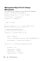
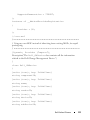
Management Object File For
Change Management . . . .
Classes for Power Management
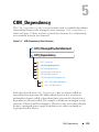
5
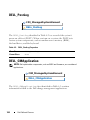
CIM_Dependency
DELL_FanSensor .
115
. . . . . . . . . . . .
. . . . . . . . . . . . . . . . .
135
136
. . . . . . . . . . . . . . . . . . . .
. . . . . . . . . . . . . . .
136
. . . . . . . . . . . . . . . .
137
CIM_PackageTempSensor
CIM_PackageVoltSensor
CIM_PackageCurrentSensor
CIM_PackageFanSensor
. . . . . . . . . . . . . .
138
. . . . . . . . . . . . . . . .
138
. . . . . . . . . . .
139
. . . . . . . . . . . . .
140
. . . . . . . . . . . . . . . . . .
140
CIM_PackagePowerSupplySensor
DELL_PackagePSRedundancy
DELL_PSRedundancy
Index
110
. . . . . . . . . . . . . .
. . . . . . . . . . . . . . . . . . . . . . . . . . . . . .
143
Contents
7
8
Contents
1
Introduction
This reference guide documents the Dell OpenManage Server Administrator
Common Information Model (CIM) provider contained in the Management
Object File (MOF) dccim32.mof.
CIM provides a conceptual model for describing manageable objects in a
systems management environment. CIM is a modeling tool rather than a
programming language. CIM provides the structure for organizing objects
into a model of a managed environment. For modeling a managed
environment, CIM makes available a set of abstract and concrete classes of
objects. These classes model the basic characteristics of systems, networks,
and applications, as well as groupings of management-related data.
For more information about CIM, see the Distributed Management Task
Force (DMTF) website at www.dmtf.org and the Microsoft website at
www.microsoft.com.
Server Administrator
Server Administrator provides a suite of systems management information for
keeping track of your networked systems. In addition to providing systems
management agents that are independent of the management console, Server
Administrator supports these systems management standards: CIM and Simple
Network Management Protocol (SNMP).
In addition to supporting systems management industry standards, Server
Administrator provides additional systems management information about
the specific components of your Dell system.
What’s New in this Release
These are the additions to this guide:
•
Added new properties to Dell_SDCardDevice
•
Added new processor families enumeration values
Introduction
9
Documenting CIM Classes and Their Properties
The Dell CIM provider extends support to Dell-specific software and
hardware components. The Dell MOF defines the classes for the Dell CIM
provider. All of the supported classes and properties in the MOF are
documented in this guide.
The following subsections define some of the basic building blocks of
CIM classes that are used in describing the dccim32 provider name.
These subsections also explain how the elements used in describing
these classes are organized. This section does not document the entire
CIM schema, but only those classes and properties supported by the
dccim32 provider. The list of properties for each supported class varies greatly.
The property values being presented could be NULL or empty string on some
systems, although in general, some non-empty values can be expected. Key
properties (listed below) will always carry non-empty values. It is
recommended that you use only the following properties as key attributes:
10
•
CIM_PhysicalElement: CreationClassName, Tag
•
CIM_System: CreationClassName, Name
•
CIM_LogicalDevice: SystemCreationClassName, SystemName,
CreationClassName, DeviceID
•
CIM_Dependency: Antecedent, Dependent
•
CIM_SoftwareElement: Name, Version, SoftwareElementState,
SoftwareElementID, TargetOperatingSystem
•
CIM_SoftwareFeature: IdentifyingNumber, ProductName, Vendor,
Version, Name
•
CIM_IRQ: CSCreationClassName, CSName, CreationClassName,
IRQNumber
•
CIM_MemoryMappedIO: CSCreationClassName, CSName,
CreationClassName, StartingAddress
•
CIM_DMA: CSCreationClassName, CSName, CreationClassName,
DMAChannel
•
CIM_RedundancyGroup: CreationClassName, Name
•
DELL_EsmLog: RecordNumber
•
DELL_PostLog: RecordNumber
Introduction
•
DELL_BIOSExtensions: systemBIOSCharacteristics
•
DELL_BIOSSettings: DisplayName
•
CIM_ServiceAccessPoint: SystemCreationClassName,
SystemName, CreationClassName, Name
Base Classes
The classes listed in the Server Administrator CIM provider class hierarchy
do not have a parent property. These base classes do not derive from
another class. The base classes are:
•
CIM_ManagedSystemElement
•
CIM_Dependency
•
DELL_EsmLog
•
DELL_PostLog
•
DELL_CMApplication
•
DELL_CMDevice
•
DELL_CMDeviceApplications
•
DELL_CMInventory
•
DELL_CMOS
•
DELL_CMProductInfo
The CIM_ManagedSystemElement class is the base class for the system
element hierarchy from which all other CIM classes are derived. As a result,
CIM_ManagedSystemElement has no parent. Examples of managed
system elements include software components such as files, devices such as
hard drives and controllers, and physical subcomponents of devices such as
chip sets and cards. For the CIM_ManagedSystemElement properties, see
Caption, CreationClassName, Description, Name, and Status in Table 1-1
The Dell-defined classes are not defined in the official schema by the DMTF,
the industry group that defines the standards for CIM, and hence do not have
parent classes. CIM_Dependency does not have a parent class because it is a
relationship or association between two managed system elements.
Introduction
11
Parent Classes
Most classes in the dccim32 provider document both a Class Name and a
Parent Class property. The parent class is the class from which any given class
inherits its core properties. For example, the CIM_Controller class has the
CIM_LogicalDevice class as its parent, and has various types of
controllers (CIM_ParallelController, CIM_SerialController) as
its children.
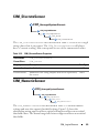
Classes That Describe Relationships
Classes that derive from CIM_Dependency have CIM_Dependency as
their parent class, but they are documented in terms of antecedent and
dependent elements in a relationship rather than in terms of common
properties. Consider the following relationship between two
CIM_ManagedSystemElements:
Antecedent
CIM_PackageCurrentSensor
Dependent
CIM_PhysicalPackage
The CIM_PackageCurrentSensor class monitors an entire physical
package, such as all the components contained in a given system chassis. The
CIM_PhysicalPackage class is dependent on the
CIM_PackageCurrentSensor class for this monitoring function.
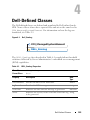
Dell-Defined Classes
Server Administrator has extended some CIM classes and has created new
classes to assist in managing systems and their components. In the diagrams
that appear in the documentation for each class, those classes created and
populated by Dell are designated by the gold (lighter gray) triangle
icon.
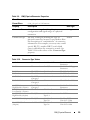
Common Properties of Classes
Many classes have properties such as Caption, Description, and
CreationClassName. Table 1-1 defines properties that have the same meaning in
every class that has this property and are defined more than once in this guide.
12
Introduction
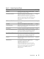
Table 1-1. Common Properties of Classes
Property
Description
Data Type
Caption
Describes the object using a short textual
description (one-line string).
string
CreationClassName
Indicates the name of the class or the
string
subclass used in the creation of an instance.
When used with the other key properties of
this class, this property allows all instances of
this class and its subclasses to be uniquely
identified.
CSCreationClassName
Indicates the computer system’s creation
class name.
string
CSName
Indicates the computer system’s name.
string
CurrentReading
Indicates the actual current value indicated sint32
by the sensor in amperes.
Description
Provides a textual description of the object.
string
LowerThresholdNonCritical If current reading is between lower threshold sint32
noncritical and upper threshold noncritical,
the current state is normal. See Figure 3-2.
LowerThresholdCritical
If the current reading is between upper
threshold critical and upper threshold fatal,
the current state is critical. See Figure 3-2.
sint32
IsLinear
Indicates that the sensor is linear over its
dynamic range.
Boolean
Manufacturer
Provides the name of the organization
string
responsible for producing the
CIM_PhysicalElement or
CIM_SoftwareElement. This may be the
entity from whom the element is purchased,
but not necessarily. Purchase information is
contained in the Vendor property of
CIM_Product.
Introduction
13
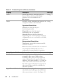
Table 1-1. Common Properties of Classes (continued)
Property
Description
Data Type
Name
Defines the label by which the object is
known. When subclassed, the Name
property can be overridden to be a
Key property.
string
Status
Provides a string indicating the status of the string
component. Status values include:
Operational Status Values:
OK indicates that the object is
functioning normally.
Degraded means that the item is
functioning, but not optimally.
Stressed indicates that the element is
functioning, but needs attention. Examples
of Stressed states are overloaded, overheated,
and so on.
Nonoperational Status Values:
Non-recover means that a nonrecoverable
error has occurred.
Error means that an element has encountered
an operational condition that is severe as
compared to its normal mode of operation.
SystemCreationClassName Indicates the system’s creation class name.
string
UnitModifier
Provides the unit multiplier for the values
sint32
returned by this sensor. All the values
returned by this sensor are represented in
units of 10 raised to the power of the unit
modifier. If the unit modifier is –6, then the
units of the values returned are microvolts.
The units apply to all numeric properties of
the sensor, unless explicitly overridden by
the units’ qualifier.
UpperThresholdCritical
If the current reading is between upper
threshold critical and upper threshold fatal,
the current status is critical. See Figure 3-2.
14
Introduction
sint32
Table 1-1. Common Properties of Classes (continued)
Property
Description
Data Type
UpperThresholdNonCritical If the current reading is between lower
threshold noncritical and lower threshold
critical, the current status is noncritical.
See Figure 3-2.
Version
sint32
Version should be in the form
string
<major>.<minor>.<revision>
or <major>.<minor><letter><revision>;
for example, 1.2.3 or 1.2a3.
Other Documents You May Need
Besides this Dell OpenManage Server Administrator CIM Reference Guide,
you can find the following documents on the Dell Support website at
support.dell.com/manuals:
•
Dell OpenManage Server Administrator User’s Guide documents the
features, installation, and uninstallation of Server Administrator.
•
Dell OpenManage Server Administrator Installation Guide contains
instructions to help you install Dell OpenManage Server Administrator.
•
Dell OpenManage Management Station Software Installation Guide
contains instructions to help you install Dell OpenManage management
station software that includes Baseboard Management Utility, DRAC
Tools, and Active Directory Snap-In.
•
Dell OpenManage Server Administrator Command Line Interface User’s
Guide explains how to perform tasks using the text-based command line
interface.
•
Dell OpenManage Server Administrator Messages Reference Guide lists the
messages that you can receive on your systems management console or on
your operating system’s event viewer. This guide explains the text, severity,
and cause of each message that the Server Administrator issues.
•
Dell OpenManage Server Administrator SNMP Reference Guide documents
the SNMP management information base (MIB). The SNMP MIB defines
variables that cover the capabilities of Server Administrator systems
management agents.
•
The Glossary for information on terms used in this document.
Introduction
15
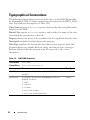
Typographical Conventions
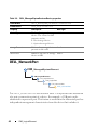
The following example shows how most of the classes in the Dell CIM provider
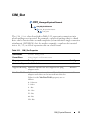
are documented. Table 1-2 shows a partial class description for the DELL_DMA
class. (For a full class description, see Table 3-42)
Class Name appears in Courier typeface and provides the string that names
the class in the MOF.
Parent Class appears in Courier typeface and provides the name of the class
from which the present class is derived.
Property denotes the name of the attribute that is being defined for this class.
Description includes text that defines the property.
Data Type stipulates the format that the values of this property must take.
Common data types include Boolean, string, and various types of integer.
Boolean indicates that the property must be expressed as one of two
alternatives.
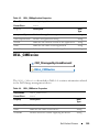
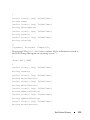
Table 1-2. CIM_DMA Properties
Class Name:
CIM_DMA
Parent Class:
CIM_SystemResource
Property
Description
DMAChannel A part of the object’s key value, the DMA channel
number.
Availability
Availability of the DMA. Availability values are
defined as follows:
1 - Other
2 - Unknown
3 - Available
4 - In Use/Not Available
5 - In Use and Available/Shareable
16
Introduction
Data Type
uint32
uint16
2
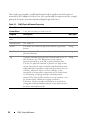
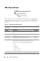
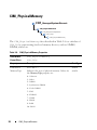
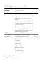
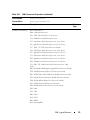
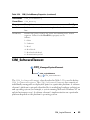
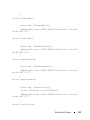
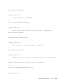
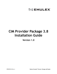
CIM_PhysicalElement
CIM_PhysicalElement is a CIM-defined class. The
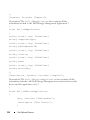
CIM_PhysicalElement class contains the subclasses shown in Figure 2-1.
Figure 2-1. CIM_PhysicalElement Class Structure
CIM_ManagedSystemElement
CIM_PhysicalElement
CIM_PhysicalPackage
CIM_PhysicalFrame
CIM_Chassis
DELL_Chassis
CIM_PhysicalComponent
CIM_Chip
CIM_PhysicalMemory
CIM_PhysicalConnector
CIM Slot
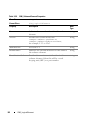
CIM_PhysicalElement
CIM_ManagedSystemElement
CIM_PhysicalElement
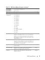
Subclasses of the CIM_PhysicalElement class listed in Table 2-1 define
any component of a system that has a distinct physical identity. Physical
elements are tangible managed system elements (usually actual hardware
items) that have a physical manifestation of some sort. By contrast, processes,
files, and logical devices are not classified as physical elements. A managed
system element is not necessarily a discrete component. A single card
(which is a type of physical element) can host more than one logical device.
CIM_PhysicalElement
17
One card, for example, could implement both a modem and a local area
network (LAN) adapter. In this case, the card would be represented by a single
physical element associated with multiple logical devices.
Table 2-1. CIM_PhysicalElement Properties
Class Name:
CIM_PhysicalElement
Parent Class:
CIM_ManagedSystemElement
Property
Description
Data Type
CreationClassN See Table 1-1.
ame
Manufacturer
See Table 1-1.
Model
The name by which the physical element is generally
known.
string
SerialNumber
A manufacturer-allocated number used to identify the
physical element.
string
Tag
Uniquely identifies the physical element and serves as string
the element’s key. The Tag property can contain
information such as asset tag or serial number data.
The key for physical element is placed very high in the
object hierarchy in order to identify the hardware/entity
independently, regardless of physical placement in or on
cabinets, adapters, and so on. For example, a hotswappable or removable component can be taken from
its containing (scoping) package and temporarily
unused. The object still continues to exist and may even
be inserted into a different scoping container.
Therefore, the key for physical element is an arbitrary
string that is defined independently of any placement or
location-oriented hierarchy.
18
CIM_PhysicalElement
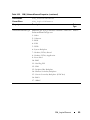
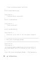
CIM_PhysicalPackage
CIM_ManagedSystemElement
CIM_PhysicalElement
CIM_PhysicalPackage
The CIM_PhysicalPackage class listed in Table 2-2 represents physical
elements that contain or host other components. Examples are a rack
enclosure or an adapter card with multiple functions.
Table 2-2. CIM_PhysicalPackage Properties
Class Name:
CIM_PhysicalPackage
Parent Class:
CIM_PhysicalElement
Property
Description
Removable
A CIM_PhysicalPackage is removable if it is
Boolean
designed to be taken in and out of the
physical container in which it is normally found
without impairing the function of the overall package.
Replaceable
A CIM_PhysicalPackage is replaceable if it is
Boolean
possible to substitute a physically different element for
the original element, as in a field replaceable unit
(FRU). For example, some computer systems allow the
microprocessor to be upgraded to one of a higher clock
rating. In this case, the microprocessor is said to be
replaceable.
Data Type
CIM_PhysicalElement
19
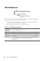
CIM_PhysicalFrame
CIM_ManagedSystemElement
CIM_PhysicalElement
CIM_PhysicalPackage
CIM_PhysicalFrame
The CIM_PhysicalFrame class described in Table 2-3 contains other
frame enclosures such as racks and chassis. Properties like VisibleAlarm or
AudibleAlarm, and data related to security breaches are also members of
this class.
Table 2-3. CIM_Physical Frame Properties
Class Name:
CIM_PhysicalFrame
Parent Class:
CIM_PhysicalPackage
Property
Description
Data Type
LockPresent
Indicates whether the frame is protected with a
lock.
Boolean
AudibleAlarm
Indicates whether the frame is equipped with an
audible alarm.
Boolean
VisibleAlarm
Indicates that the equipment includes a
visible alarm.
Boolean
SecurityBreach
uint16
An enumerated, integer-valued property
indicating that a physical breach of the frame is in
progress. Values for the SecurityBreach property
are:
1 - Other
2 - Unknown
3 - No breach
4 - Breach attempted
5 - Breach successful
IsLocked
20
Indicates that the frame is currently locked.
CIM_PhysicalElement
Boolean
CIM_Chassis
CIM_ManagedSystemElement
CIM_PhysicalElement
CIM_PhysicalPackage
CIM_PhysicalFrame
CIM_Chassis
The CIM_Chassis class described in Table 2-4 represents the physical
elements that enclose physical elements such as power supplies, fans,
and processors.
Table 2-4. CIM_Chassis Parent Properties
Class Name:
CIM_Chassis
Parent Class:
CIM_PhysicalFrame
Property
Description
Data Type
ChassisTypes
Values for the ChassisTypes property are:
uint16
1 - Other
2 - Unknown
3 - Mini-tower
4 - Tower
5 - Space-saving
6 - Main system chassis
7 - Expansion chassis
8 - Subchassis
9 - Space-saving
10 - Main system chassis
11 - Expansion chassis
12 - Subchassis
13 - Bus expansion chassis
14 - Peripheral chassis
15 - Storage chassis
16 - Rack-mount chassis
CIM_PhysicalElement
21
DELL_Chassis
CIM_ManagedSystemElement
CIM_PhysicalElement
CIM_PhysicalPackage
CIM_PhysicalFrame
CIM_Chassis
DELL_Chassis
The DELL_Chassis class explained in Table 2-5 defines the identifying and
status properties of the chassis. DELL_Chassis inherits from CIM-defined
classes, but is populated by Dell properties.
Table 2-5. DELL_Chassis Properties
Class Name:
DELL_Chassis
Parent Class:
CIM_Chassis
Property
Description
Data Type
AssetTag
Indicates the container AssetTag string. This
asset tag string is writable by the system
administrator.
string
SystemClass
Refers to the system type that is installed and
running the instrumentation. Values for the
SystemClass property are:
uint16
1 - Other
2 - Unknown
3 - Workstation
4 - Server
5 - Desktop
6 - Portable
7 - Net PC
SystemID
22
Indicates the system identifier code.
CIM_PhysicalElement
uint16
Table 2-5. DELL_Chassis Properties (continued)
Class Name:
DELL_Chassis
Parent Class:
CIM_Chassis
Property
Description
LogFormat
Defines whether the event log data is unicode uint16
formatted or binary (raw). Values for the event
LogFormat property are:
Data Type
1 - Formatted (event log only)
2 - Unformatted
3 - Events_and_POST_Formatted (both the event
log and the power-on self-test (POST) log are
unicode for matted)
FanStatus
Indicates the global status of fan sensors.
string
TempStatus
Indicates the global status of temperature
sensors.
string
VoltStatus
Indicates the global status of voltage sensors.
string
AmpStatus
Indicates the global status of current sensors.
string
PsStatus
Indicates the global status of power supplies.
string
MemStatus
Indicates the global status of memory devices. string
ProcStatus
Indicates the global status of processor devices. string
FanRedStatus
Indicates the global status of the cooling unit. string
PsRedStatus
Indicates the global status of the power unit.
IsDefaultThrSupported
Indicates whether resetting default thresholds Boolean
are supported.
string
ChassisSystemProperties Indicates chassis characteristics, such as energy uint16
smart etc.
ChassisSystemRevision
Indicates the chassis revision.
uint16
EsmLogStatus
Indicates the global status of ESM log.
string
MemoryRedStatus
Indicates the global status of memory
redundancy.
string
CIM_PhysicalElement
23
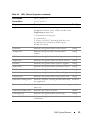
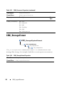
CIM_PhysicalComponent
CIM_ManagedSystemElement
CIM_PhysicalElement
CIM_PhysicalComponent
The CIM_PhysicalComponent class listed in Table 2-6 represents any
low-level or basic component within a package. A component object either
cannot or does not need to be broken down into its constituent parts. For
example, an application specific integrated circuit (ASIC) cannot be broken
down into smaller discrete parts.
Table 2-6. CIM_PhysicalComponent Properties
Class Name:
CIM_PhysicalComponent
Parent Class:
CIM_PhysicalElement
CIM_Chip
CIM_ManagedSystemElement
CIM_PhysicalElement
CIM_PhysicalComponent
CIM_Chip
The CIM_Chip class listed in Table 2-7 represents any type of integrated
circuit hardware, including ASICs, processors, memory chips, and so on.
24
CIM_PhysicalElement
Table 2-7. CIM_Chip Properties
Class Name:
CIM_Chip
Parent Class:
CIM_PhysicalComponent
Property
Description
Data Type
FormFactor
0 - Unknown
uint16
1 - Other
2 - SIP
3 - DIP
4 - ZIP
5 - SOJ
6 - Proprietary
7 - SIMM
8 - DIMM
9 - TSOP
10 - PGA
11 - RIMM
12 - SODIMM
13 - SRIMM
14 - SMD
15 - SSMP
16 - QFP
17 - TQFP
18 - SOIC
19 - LCC
20 - PLCC
21 - BGA
22 - FPBGA
23 - LGA
24 - FB-DIMM
CIM_PhysicalElement
25
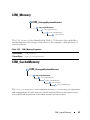
CIM_PhysicalMemory
CIM_ManagedSystemElement
CIM_PhysicalElement
CIM_PhysicalComponent
CIM_Chip
CIM_PhysicalMemory
The CIM_PhysicalMemory class described in Table 2-8 is a subclass of
CIM_Chip, representing low-level memory devices, such as SIMMS,
DIMMs, and so on.
Table 2-8. CIM_PhysicalMemory Properties
Class Name:
CIM_PhysicalMemory
Parent Class:
CIM_Chip
Property
Description
Data Type
FormFactor
See Table 2-7.
uint16
MemoryType
Indicates the type of physical memory. Values for
the MemoryType property are:
uint16
0 - Unknown
1 - Other
2 - DRAM
3 - Synchronous DRAM
4 - Cache DRAM
5 - EDO
6 - EDRAM
7 - VRAM
8 - SRAM
9 - RAM
10 - ROM
26
CIM_PhysicalElement
Table 2-8. CIM_PhysicalMemory Properties (continued)
Class Name:
CIM_PhysicalMemory
Parent Class:
CIM_Chip
Property
Description
MemoryType
(continued)
11 - Flash
Data Type
12 - EEPROM
13 - FEPROM
14 - EPROM
15 - CDRAM
16 - 3DRAM
17 - SDRAM
18 - SGRAM
19 - RDRAM
20 - DDR
21 - DDR2
22 - DDR2 FB-DIMM
24 - DDR3
25 - FBD2
TotalWidth
Indicates the total width, in bits, of the physical
memory, including check or error correction bits.
If there are no error correction bits, the value in
this property should match that specified for the
DataWidth property.
uint16
DataWidth
Indicates the data width, in bits, of the physical
memory. A data width of 0 and a total width of 8
would indicate that the memory is solely used to
provide error correction bits.
uint16
Speed
Indicates the speed of the physical memory, in
nanoseconds.
uint32
SpeedAsString
Indicates the accurate speed of the physical
memory, in string format (with units).
string
Capacity
Indicates the total capacity of this physical
memory, in bytes.
uint64
CIM_PhysicalElement
27
Table 2-8. CIM_PhysicalMemory Properties (continued)
Class Name:
CIM_PhysicalMemory
Parent Class:
CIM_Chip
Property
Description
BankLabel
A string identifying the physically labeled bank
string
where the memory is located, for example, "Bank 0"
or "Bank A."
PositionInRow
Specifies the position of the physical memory in a
“row.” For example, if it takes two 8-bit memory
devices to form a 16-bit row, then a value of 2
means that this memory is the second device.
0 is an invalid value for this property.
Data Type
uint32
InterleavePosition Indicates the position of this physical memory in uint32
an interleave. 0 indicates noninterleaved.
1 indicates the first position, 2 the second
position, and so on. For example, in a 2:1
interleave, a value of 1 indicates that the memory is
in the “even” position.
CIM_PhysicalConnector
CIM_ManagedSystemElement
CIM_PhysicalElement
CIM_PhysicalConnector
The CIM_PhysicalConnector class explained in Table 2-9 includes
physical elements such as plugs, jacks, or buses that connect physical
elements. Any object that can be used to connect and transmit signals or
power between two or more physical elements is a member of this class. For
example, slots and D-shell connectors are types of physical connectors. See
Table 2-10 for a list of valid connector type values.
28
CIM_PhysicalElement
Table 2-9. CIM_PhysicalConnector Properties
Class Name:
CIM_PhysicalConnector
Parent Class:
CIM_PhysicalElement
Property
Description
Data Type
ConnectorPinout A free-form string describing the pin
configuration and signal usage of a physical
connector.
ConnectorType
Table 2-10.
string
An array of integers defining the type of
uint16
physical connector. An array is specified to allow
the description of “combinations” of connector
information. For example, one array entry could
specify RS-232, another DB-25, and a third
entry could define the connector as male. See
Table 2-10 for the values of the ConnectorType
property.
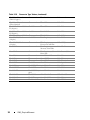
Connector Type Values
0 - Unknown
30 - unused
60 - Micro-DIN
90 - On Board IDE
Connector
1 - Other
31 - unused
61 - PS/2
91 - On Board Floppy
Connector
2 - Male
32 - IEEE-48
62 - Infrared
92 - 9 Pin Dual Inline
3 - Female
33 - AUI
63 - unused
93 - 25 Pin Dual Inline
4 - Shielded
34 - UTP
Category 3
64 - Access. bus
94 - 50 Pin Dual Inline
5 - Unshielded
35 - UTP
Category 4
65 - unused
95 - 68 Pin Dual Inline
6 - SCSI (A)
High-Density (50 pins)
36 - UTP
Category 5
66 - Centronics
96 - On Board Sound
Connector
7 - SCSI (A)
Low-Density (50 pins)
37 - BNC
67 - Mini-Centronics 97 - Mini-jack
8 - SCSI (P)
High-Density (68 pins)
38 - RJ11
68 - Mini-Centronics 98 - PCI-X
Type-14
9 - SCSI SCA-I (80 pins) 39 - RJ45
10 - SCSI SCA-II
(80 pins)
69 - Mini-Centronics 99 - Sbus IEEE
Type-20
1396-1993 32-bit
40 - Fiber MIC 70 - Mini-Centronics 100 - Sbus IEEE
Type-26
1396-1993 64-bit
CIM_PhysicalElement
29
Table 2-10. Connector Type Values (continued)
11 - Fibre Channel
(DB-9 Copper)
41 - unused
71 - Bus Mouse
101 - unused
12 - Fibre Channel
(Fiber Optical)
42 - unused
72 - ADB
102 - GIO
13 - Fibre Channel SCA- 43 - PCI
II (40 pins)
73 - AGP
103 - XIO
14 - Fibre Channel SCA- 44 - ISA
II (20 pins)
74 - VME Bus
104 - HIO
15 - Fibre Channel BNC 45 - unused
75 - VME64
105 - NGIO
16 - ATA 3-1/2 Inch
(40 pins)
46 - VESA
76 - Proprietary
106 - PMC
17 - ATA 2-1/2 Inch
(44 pins)
47 - unused
77 - Proprietary
Processor Card Slot
107 - MTRJ
18 - ATA-2
48 - unused
78 - Proprietary
Memory Card Slot
108 - VF-45
19 - ATA-3
49 - unused
79 - Proprietary I/O
Riser Slot
109 - Future I/O
20 - ATA/66
50 - unused
80 - PCI-66 MHz
110 - SC
21 - DB-9
51 - unused
81 - AGP2X
111 - SG
22 - DB-15
52 - unused
82 - AGP4X
112 - Electrical
23 - DB-25
53 - USB
83 - PC-98
113 - Optical
24 - DB-36
54 - IEEE 1394 84 - PC-98-Hireso
114 - Ribbon
25 - RS-232C
55 - HIPPI
115 - GLM
26 - RS-422
56 - HSSDC (6 86 - PC-98Note
pins)
116 - 1x9
117 - Mini SG
85 - PC-H98
27 - RS-423
57 - GBIC
87 - PC-98Full
28 - RS-485
58 - DIN
88 - SSA SCSI
118 - LC
29 - RS-449
59 - Mini-DIN
89 - Circular
119 - HSSC
30
CIM_PhysicalElement
CIM_Slot
CIM_ManagedSystemElement
CIM_PhysicalElement
CIM_PhysicalConnector
CIM_Slot
The CIM_Slot class described in Table 2-11 represents connectors into
which packages are inserted. For example, a physical package that is a hard
drive can be inserted into a small computer system interface-single connector
attachment (SCSI-SCA) slot. As another example, a card can be inserted
into a 16-, 32-, or 64-bit expansion slot on a host board.
Table 2-11.
CIM_Slot Properties
Class Name:
class CIM_Slot
Parent Class:
CIM_PhysicalConnector
Property
Description
Data Type
ConnectorType
See Table 2-10.
uint16
SupportsHotPlug Indicates whether the slot supports hot-plug
adapter cards.
Boolean
MaxDataWidth
uint16
Indicates the maximum bus width in bits of
adapter cards that can be inserted into this slot.
Values for the MaxDataWidth property are as
follows:
0 - Unknown
1 - Other
8 - Bits
16 - Bits
32 - Bits
64 - Bits
128 - Bits
CIM_PhysicalElement
31
Table 2-11. CIM_Slot Properties (continued)
Class Name:
class CIM_Slot
Parent Class:
CIM_PhysicalConnector
Property
Description
SystemSlotType
Indicates the type of system slot. Values for the
SystemSlotType property are as follows:
1 - Other
2 - Unknown
3 - ISA
4 - MCA
5 - EISA
6 - PCI
7 - PCMCIA
8 - VL-VESA
9 - Proprietary
10 - Processor Card Slot
11 - Proprietary Memory Card Slot
12 - I/O Riser Card Slot
13 - NuBus
14 - PCI - 66MHz Capable
15 - AGP
16 - AGP 2X
17 - AGP 4X
18 - PCI-X
19 - AGP 8X
160 - PC-98/C20
161 - PC-98/C24
32
CIM_PhysicalElement
Data Type
Table 2-11.
CIM_Slot Properties (continued)
Class Name:
class CIM_Slot
Parent Class:
CIM_PhysicalConnector
Property
Description
Contd.
162 - PC-98/E
Data Type
163 - PC-98/Local Bus
164 - PC-98/Card
165 - PCI Express
166 - PCI Express x1
167 - PCI Express x2
168 - PCI Express x4
169 - PCI Express x8
170 - PCI Express x16
171 - PCI Express Gen 2
172 - PCI Express Gen 2 x1
173 - PCI Express Gen 2 x2
174 - PCI Express Gen 2 x4
175 - PCI Express Gen 2 x8
176 - PCI Express Gen 2 x16
CIM_PhysicalElement
33
34
CIM_PhysicalElement
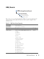
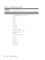
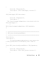
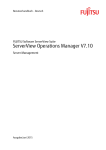
3
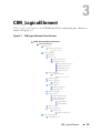
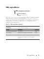
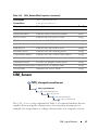
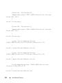
CIM_LogicalElement
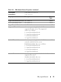
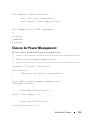
CIM_LogicalElement is a CIM-defined class containing the subclasses
shown in Figure 3-1.
Figure 3-1. CIM_LogicalElement Class Structure
CIM_ManagedSystemElement
CIM_LogicalElement
CIM_System
CIM_ComputerSystem
DELL_Chassis
CIM_LogicalDevice
CIM_FRU
CIM_Sensor
CIM_DiscreteSensor
CIM_NumericSensor
CIM_TemperatureSensor
CIM_CurrentSensor
CIM_VoltageSensor
CIM_Tachometer
CIM_LogicalPort
CIM_NetworkPort
DELL_NetworkPort
CIM_Watchdog
CIM_CoolingDevice
CIM_Fan
CIM_UserDevice
CIM_PointingDevice
CIM_Keyboard
CIM_PowerSupply
CIM_Controller
CIM_ParallelController
CIM_SerialController
CIM_PCIController
CMI_PCIDevice
CMI_PCIBridge
CIM_Processor
CIM_StorageExtent
CIM_Memory
CIM_CacheMemory
CIM_SoftwareElement
CIM_BIOSElement
CIM_LogicalElement
35
CIM_SoftwareFeature
DELL_SoftwareFeature
CIM_SystemResource
CIM_IRQ
CIM_MemoryMappedIO
CIM_DMA
CIM_RedundancyGroup
CIM_ExtraCapacityGroup
DELL_PSRedundancyGroup
DELL_FanRedundancyGroup
CIM_EnabledLogicalElement
CIM_ServiceAccessPoint
CIM_RemoteServiceAccessPoint
DELL_RemoteServiceAccessPort
CIM_LogicalElement
CIM_ManagedSystemElement
CIM_LogicalElement
Table 3-1 lists the following characteristics for members of the
CIM_LogicalElement class:
•
Represent abstractions used to manage and coordinate aspects of a
physical environment such as files, processes, systems, system capabilities,
and network components in the form of logical devices
•
Represent devices, where devices are abstractions of hardware entities that
may or may not be realized in physical hardware
Table 3-1. CIM_LogicalElement Properties
Class Name:
CIM_LogicalElement
Parent Class:
CIM_ManagedSystemElement
36
CIM_LogicalElement
CIM_System
CIM_ManagedSystemElement
CIM_LogicalElement
CIM_System
The CIM_System class shown in Table 3-2 defines a collection of managed
system elements that operates as a functional whole. An instance of the
CIM_System class contains a well-defined list of components that work
together to perform a specific function.
Table 3-2. CIM_System Properties
Class Name:
CIM_System
Parent Class:
CIM_LogicalElement
Property
Description
Data Type
CreationClassName
See Table 1-1.
string
Name
Indicates the name of a specific system, such as a string
particular storage system or server.
PrimaryOwnerContact Provides information on how the primary system string
owner can be reached, for example, a phone
number or e-mail address.
PrimaryOwnerName
Indicates the name of the primary system owner. string
Roles
An array of strings that specifies the roles this
string
system plays in the IT environment. For example,
for an instance of a network system, the Roles
property might contain the string "storage system."
CIM_LogicalElement
37
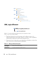
CIM_ComputerSystem
CIM_ManagedSystemElement
CIM_LogicalElement
CIM_System
CIM_ComputerSystem
The CIM_ComputerSystem class listed in Table 3-3 contains some or all of
the following CIM_ManagedSystemElements: file system, operating
system, processor, and memory (volatile and/or nonvolatile storage).
For properties, see Table 3-2.
Table 3-3. CIM_ComputerSystem Properties
Class Name:
CIM_ComputerSystem
Parent Class:
CIM_System
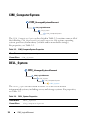
DELL_System
CIM_ManagedSystemElement
CIM_LogicalElement
CIM_System
CIM_ComputerSystem
DELL_System
The DELL_System class listed in Table 3-4 is the set of all Dell
instrumented systems, including server, and storage systems. For properties,
see Table 3-2.
Table 3-4. DELL_System Properties
Class Name:
DELL_System
Parent Class:
CIM_ComputerSystem
38
CIM_LogicalElement
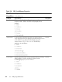
CIM_LogicalDevice
CIM_ManagedSystemElement
CIM_LogicalElement
CIM_LogicalDevice
The CIM_LogicalDevice class described in Table 3-5 models a hardware
entity that may be realized in physical hardware. CIM_LogicalDevice
includes any characteristics of a logical device that manages its operation or
configuration. An example of a logical device is a temperature sensor’s
reading of actual temperature.
Table 3-5. CIM_Logical Device Properties
Class Name:
CIM_LogicalDevice
Parent Class:
CIM_LogicalElement
Property
Description
Data Type
SystemCreationClassName
See Table 1-1.
string
SystemName
Indicates the scoping system’s name.
string
CreationClassName
See Table 1-1.
string
DeviceID
Identifies an address or other identifying
information to uniquely name the logical
device.
string
CIM_LogicalElement
39
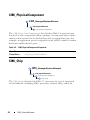
CIM_FRU
CIM_ManagedSystemElement
CIM_LogicalElement
CIM_LogicalDevice
CIM_FRU
The CIM_FRU class described in Table 3-6 contains manufacturing
information related to the Field Replaceable Units (FRU) of a system such as
a system planar or I/O riser card.
Table 3-6. CIM_FRU Properties
Class Name:
CIM_FRU
Parent Class:
CIM_LogicalDevice
Property
Description
Data Type
FRUInformationState
Indicates the state and availability of
FRU information.
uint 16
FRUDeviceName
Indicates the device name of the FRU
string
FRUManufacturingDateName Indicates the manufacturing date of the
FRU in ticks.
datetime
FRUManufacturerName
Indicates the name of the manufacturer. string
FRUPartNumberName
Indicates the FRU part number.
string
FRUSerialNumberName
Indicates the FRU serial number.
string
FRURevisionName
Indicates the FRU Revision number.
string
40
CIM_LogicalElement
CIM_LogicalPort
CIM_ManagedSystemElement
CIM_LogicalElement
CIM_LogicalDevice
CIM_LogicalPort
The CIM_LogicalPort class listed in Table 3-7 represents the abstraction
of a port or connection point of a device. For example, a USB port can be
abstracted to represent a port. This feature is used when the abstracted port
has independent management characteristics from the device that includes it.
Table 3-7. CIM_LogicalPort Properties
Class Name:
CIM_LogicalPort
Parent Class:
CIM_LogicalDevice
Property
Description
Data Type
Speed
Indicates the bandwidth of the port in bits per
second.
uint64
MaxSpeed
Indicates the maximum bandwidth of the port in
bits per second.
uint64
RequestedSpeed
Indicates the requested bandwidth of the port in bits uint64
per second.
UsageRestriction
Indicates usage parameters for the port. For example, uint16
a storage array may have back end ports to
communicate with disk drives and front end ports to
communicate with hosts.
CIM_LogicalElement
41
CIM_NetworkPort
CIM_ManagedSystemElement
CIM_LogicalElement
CIM_LogicalDevice
CIM_LogicalPort
CIM_NetworkPort
The CIM_NetworkPort class listed in Table 3-8 describes the logical
representation of a network.
Table 3-8. CIM_NetworkPort Properties
Class Name:
CIM_NetworkPort
Parent Class:
CIM_LogicalPort
Property
Description
Data Type
Speed
Indicates the bandwidth of the port in bits per
second.
uint64
PortType
Identifies port type and whether it is DMTF
uint16
reserved or vendor reserved. When this property is
set to 1 (Other), the OtherPropertyType property
contains a string description of the port type.
OtherPortType
When used in conjunction with PortType, this
property identifies port type.
LinkTechnology
Enumerates the types of links to the device. When uint16
this property is set to 1, the OtherLinktechnology
property displays relevant links to the device.
OtherLinkTechnology When used in conjunction with Link Technology,
this property displays relevant links to the device.
string
string
PermanentAddress
Defines the network address hardcoded into a port. string
NetworkAddresses
Indicates the network addresses for a port.
42
CIM_LogicalElement
string
Table 3-8. CIM_NetworkPort Properties (continued)
Class Name:
CIM_NetworkPort
Parent Class:
CIM_LogicalPort
Property
Description
Data Type
FullDuplex
Indicates whether the port is operating in a full
duplex mode.
Boolean
AutoSense
Indicates whether the Network Port is capable of
automatically determining the speed or other
characteristics of network attached media.
Boolean
SupportedMaximum Indicates the maximum transmission unit
TransmissionUnit
supported.
uint64
ActiveMaximumTran Indicates the active or negotiated maximum
smissionUnit
transmission unit supported.
uint64
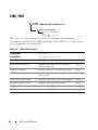
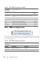
DELL_ManagedSystemServicesDevice
The DELL_ManagedSystemServicesDevice class listed in Table 3-9
defines the type, size of storage devices in MB, and related information.
CIM_LogicalElement
43
Table 3-9. DELL_ManagedSystemServicesDevice properties
Class Name:
DELL_ManagedSystemServicesDevice
Parent Class:
CIM_LogicalDevice
Property
Description
Data Type
deviceType
Defines the type of storage
device. The values for this
property can be:
uint8
0 - Base managed device
1 - Optional managed device
storagePresent
Defines the storage device
present on the card.
boolean
deviceSize
Indicates the size of storage uint32
device in MB.
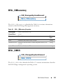
DELL_NetworkPort
CIM_ManagedSystemElement
CIM_LogicalElement
CIM_LogicalDevice
CIM_LogicalPort
CIM_NetworkPort
DELL_NetworkPort
The DELL_NetworkPort class listed in Table 3-10 represents the abstraction
of a port or connection point of a device. For example, a USB port can be
abstracted to represent a port. This feature is used when the abstracted port has
independent management characteristics from the device that includes it.
44
CIM_LogicalElement
Table 3-10.
DELL_NetworkPort Properties
Class Name:
Dell_NetworkPort
Parent Class:
CIM_NetworkPort
Property
Description
Data Type
NicTOECapability
Defines NIC TCP Offload Engine (TOE)
capability. The following values, with
explanations, are possible for this property:
uint32
0 - NIC/driver does not support querying for
capability.
1 - NIC/driver supports querying for capability but
query returned an error.
2 - NIC/driver supports querying for capability and
query says it is capable.
4 - NIC/driver supports querying for capability and
query says it is not capable.
8 - NIC/driver supports querying for capability but
error prevented querying NIC/driver.
16 - NIC/driver supports querying for capability but
NIC/driver did not respond to query.
NicRDMACapability
Defines NIC Remote Direct Memory Access
uint32
(RDMA) capability. The following values, with
explanations, are possible for this property:
0 - NIC/driver does not support querying for
capability.
1 - NIC/driver supports querying for capability but
query returned an error.
2 - NIC/driver supports querying for capability and
query says it is capable.
4 - NIC/driver supports querying for capability and
query says it is not capable.
8 - NIC/driver supports querying for capability but
error prevented querying NIC/driver.
16 - NIC/driver supports querying for capability but
NIC/driver did not respond to query.
CIM_LogicalElement
45
Table 3-10. DELL_NetworkPort Properties (continued)
Class Name:
Dell_NetworkPort
Parent Class:
CIM_NetworkPort
Property
Description
NiciSCSICapability
Defines NIC Internet Small Computer System uint32
Interface (iSCSI) Capability. The following
values, with explanations, are possible for this
property:
Data Type
0 - NIC/driver does not support querying for
capability.
1 - NIC/driver supports querying for capability but
query returned an error.
2 - NIC/driver supports querying for capability and
query says it is capable.
4 - NIC/driver supports querying for capability and
query says it is not capable.
8 - NIC/driver supports querying for capability but
error prevented querying NIC/driver.
16 - NIC/driver supports querying for capability but
NIC/driver did not respond to query.
IsTOEEnable
Indicates whether TOE is enabled.
Boolean
IsRDMAEnable
Indicates whether RDMA is enabled.
Boolean
IsiSCSIEnable
Indicates whether SCSI is enabled.
Boolean
NicStatus
Indicates NIC /driver status. The following
values are possible:
uint32
0 - Unknown
1 - Connected
2 - Disconnected
3 - Driver Bad
4 - Driver Disabled
10 - Hardware initializing
11 - Hardware resetting
12 - Hardware closing
13 - Hardware not ready
46
CIM_LogicalElement
Table 3-10.
DELL_NetworkPort Properties (continued)
Class Name:
Dell_NetworkPort
Parent Class:
CIM_NetworkPort
Property
Description
Data Type
BusNumber
Indicates the PCI bus number.
uint8
FunctionNumber
Indicates the PCI Function number.
uint8
Driver version
Indicates the NIC driver version.
string
IPAddress
Indicates the NIC IP Address.
string
SubnetMask
Indicates the NIC subnet mask.
string
DHCPServer
Indicates the NIC DHCP Server.
string
DefaultGateway
Indicates the NIC default gateway.
string
CurrentMACAddress
Indicates the NIC current MAC address.
string
OSAdapterDescription
Describes the OS Adapter.
string
OSAdapterVendor
Provides OS Adapter vendor details.
string
OSAdapterProductName Identifies the OS Adapter name.
string
ServiceName
string
Identifies the Service Name.
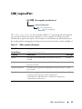
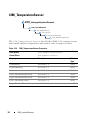
CIM_Sensor
CIM_ManagedSystemElement
CIM_LogicalElement
CIM_LogicalDevice
CIM_Sensor
CIM_NumericSensor
CIM_CurrentSensor
The CIM_Sensor class explained in Table 3-11 contains hardware devices
capable of measuring the characteristics of some physical property, for
example, the temperature or voltage characteristics of a computer system.
CIM_LogicalElement
47
Table 3-11. CIM_Sensor Properties
Class Name:
CIM_Sensor
Parent Class:
CIM_LogicalDevice
Property
Description
Data Type
SensorType
The type of the sensor, for example, voltage or
temperature sensor.
uint16
Values for the SensorType property are:
0 - Unknown
1 - Other
2 - Temperature sensors measure the environmental
temperature.
3 - Voltage sensors measure electrical voltage.
4 - Current sensors measure current readings.
5 - Tachometers measure speed/revolutions of a device.
For example, a fan device can have an associated
tachometer that measures its speed.
6 - Batteries maintain the time and date and save the
system’s BIOS configuration when the system is
switched off.
OtherSensorType The type of sensor when the SensorType property is
Description
set to Other.
string
PossibleStates
Enumerates the string outputs of the sensor. For
string
example, a NumericSensor can report states based on
threshold readings.
CurrentState
Indicates the current state of the sensor. This value is string
always one of the Possible States.
PollingInterval
Indicates the polling interval, in nanoseconds, that
the sensor hardware or instrumentation uses to
determine the current state of the sensor.
48
CIM_LogicalElement
uint64
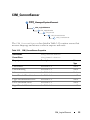
CIM_DiscreteSensor
CIM_ManagedSystemElement
CIM_LogicalElement
CIM_LogicalDevice
CIM_Sensor
CIM_DiscreteSensor
The CIM_DiscreteSensor class described in Table 3-12 has a set of legal
string values that it can report. The CIM_DiscreteSensor will always
have a "current reading" that corresponds to one of the enumerated values.
Table 3-12.
CIM_DiscreteSensor Properties
Class Name:
CIM_DiscreteSensor
Parent Class:
CIM_Sensor
Property
Description
Data Type
CurrentReading See Table 1-1.
sint32
PossibleValues
sint32
Enumerates the string outputs that can be reported by
the sensor.
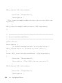
CIM_NumericSensor
CIM_ManagedSystemElement
CIM_LogicalElement
CIM_LogicalDevice
CIM_Sensor
CIM_NumericSensor
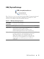
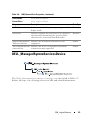
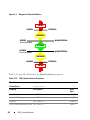
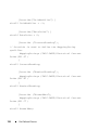
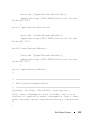
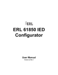
The CIM_NumericSensor class described in Table 3-13 returns numeric
settings and may also support threshold settings. Figure 3-2 shows the
relationship among upper and lower critical and upper and lower non-critical
threshold values. The normal range falls between upper and lower non-critical
thresholds.
CIM_LogicalElement
49
Figure 3-2. Ranges for Threshold Values
FATAL
CRITICAL
UPPER
WARNING
UPPER
User Definable
NONCRITICAL
NORMAL
LOWER
User Definable
NONCRITICAL
WARNING
LOWER
CRITICAL
FATAL
Table 3-13 provides definitions for NumericSensor properties.
Table 3-13. CIM_NumericSensor Properties
Class Name:
CIM_NumericSensor
Parent Class:
CIM_Sensor
Property
Description
Data
Type
UnitModifier
See Table 1-1.
sint32
CurrentReading
See Table 1-1.
sint32
IsLinear
See Table 1-1.
Boolean
LowerThresholdNonCritical See Table 1-1.
50
CIM_LogicalElement
sint32
Table 3-13.
CIM_NumericSensor Properties (continued)
Class Name:
CIM_NumericSensor
Parent Class:
CIM_Sensor
Property
Description
Data
Type
UpperThresholdNonCritical See Table 1-1.
sint32
LowerThresholdCritical
See Table 1-1.
sint32
UpperThresholdCritical
See Table 1-1.
sint32
SupportedThresholds
An array representing the thresholds
supported by this sensor. The supported
values are as follows:
uint16
1 - LowerThresholdNonCritical
2 - UpperThresholdNonCritical
3 - LowerThresholdCritical
4 - UpperThresholdCritical
EnabledThresholds
An array representing the thresholds that are uint16
currently enabled for this sensor.
Enabled threshold values are as follows:
1 - LowerThresholdNonCritical
2 - UpperThresholdNonCritical
3 - LowerThresholdCritical
4 - UpperThresholdCritical
SettableThresholds
An array representing the writable thresholds uint16
supported by sensor.
Settable threshold values are:
1 - LowerThresholdNonCritical
2 - UpperThresholdNonCritical
CIM_LogicalElement
51
CIM_TemperatureSensor
CIM_ManagedSystemElement
CIM_LogicalElement
CIM_LogicalDevice
CIM_Sensor
CIM_NumericSensor
CIM_TemperatureSensor
The CIM_TemperatureSensor class listed in Table 3-14 contains sensors
that sample ambient temperature and return a value in degrees Celsius.
Table 3-14. CIM_TemperatureSensor Properties
Class Name:
CIM_TemperatureSensor
Parent Class:
CIM_NumericSensor
Property
Description
Data
Type
UnitModifier
See Table 1-1.
sint32
CurrentReading
See Table 1-1.
sint32
IsLinear
See Table 1-1.
Boolean
LowerThresholdNonCritical
See Table 1-1.
sint32
UpperThresholdNonCritical
See Table 1-1.
sint32
LowerThresholdCritical
See Table 1-1.
sint32
UpperThresholdCritical
See Table 1-1.
sint32
52
CIM_LogicalElement
CIM_CurrentSensor
CIM_ManagedSystemElement
CIM_LogicalElement
CIM_LogicalDevice
CIM_Sensor
CIM_NumericSensor
CIM_CurrentSensor
The CIM_CurrentSensor class listed in Table 3-15 contains sensors that
measure amperage and returns a value in amperes and watts.
Table 3-15.
CIM_CurrentSensor Properties
Class Name:
CIM_CurrentSensor
Parent Class:
CIM_NumericSensor
Property
Description
Data
Type
UnitModifier
See Table 1-1.
sint32
CurrentReading
See Table 1-1.
sint32
IsLinear
See Table 1-1.
Boolean
LowerThresholdNonCritical
See Table 1-1.
sint32
UpperThresholdNonCritical
See Table 1-1.
sint32
LowerThresholdCritical
See Table 1-1.
sint32
UpperThresholdCritical
See Table 1-1.
sint32
CIM_LogicalElement
53
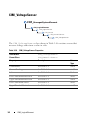
CIM_VoltageSensor
CIM_ManagedSystemElement
CIM_LogicalElement
CIM_LogicalDevice
CIM_Sensor
CIM_NumericSensor
CIM_VoltageSensor
The CIM_VoltageSensor class shown in Table 3-16 contains sensors that
measure voltage and return a value in volts.
Table 3-16. CIM_VoltageSensor Properties
Class Name:
CIM_VoltageSensor
Parent Class:
CIM_NumericSensor
Property
Description
Data
Type
UnitModifier
See Table 1-1.
sint32
CurrentReading
See Table 1-1.
sint32
IsLinear
See Table 1-1.
Boolean
LowerThresholdNonCritical
See Table 1-1.
sint32
UpperThresholdNonCritical
See Table 1-1.
sint32
LowerThresholdCritical
See Table 1-1.
sint32
UpperThresholdCritical
See Table 1-1.
sint32
54
CIM_LogicalElement
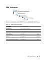
CIM_Tachometer
CIM_ManagedSystemElement
CIM_LogicalElement
CIM_LogicalDevice
CIM_Sensor
CIM_NumericSensor
CIM_Tachometer
The CIM_Tachometer class listed in Table 3-17 contains devices that
measure revolutions per minute (RPM) of a fan and return the value in RPMs.
Table 3-17.
CIM_Tachometer Properties
Class Name:
CIM_Tachometer
Parent Class:
CIM_NumericSensor
Property
Description
Data Type
SensorType
See Table 1-1.
uint16
UnitModifier
See Table 1-1.
sint32
CurrentReading
See Table 1-1.
sint32
IsLinear
See Table 1-1.
Boolean
LowerThresholdNonCritical
See Table 1-1.
sint32
UpperThresholdNonCritical
See Table 1-1.
sint32
CIM_LogicalElement
55
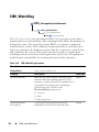
CIM_WatchDog
CIM_ManagedSystemElement
CIM_LogicalElement
CIM_LogicalDevice
CIM_Watchdog
The CIM_WatchDog class described in Table 3-18 represents a timer that is
implemented in system hardware. The watchdog feature allows the hardware to
monitor the state of the operating system, BIOS, or a software component
installed on the system. If the monitored component fails to rearm the timer
before its expiration, the hardware assumes that the system is in a critical state
and could reset the system. This feature can also be used as an application
watchdog timer for a mission-critical application. In this case, the application
would assume responsibility for rearming the timer before expiration.
Table 3-18. CIM_WatchDog Properties
Class Name:
CIM_WatchDog
Parent Class:
CIM_LogicalDevice
Property
Description
MonitoredEntity
Indicates the entity that is currently being
uint16
monitored by the watchdog feature. This
property is used to identify the module that is
responsible for rearming the watchdog at
periodic intervals. Values for the
MonitoredEntity property are:
Data Type
1 - Unknown
2 - Other
3 - Operating System
MonitoredEntity
Description
56
A string describing additional textual
information about the monitored entity.
CIM_LogicalElement
string
Table 3-18.
CIM_WatchDog Properties (continued)
Class Name:
CIM_WatchDog
Parent Class:
CIM_LogicalDevice
Property
Description
Data Type
TimeoutInterval
Indicates the time-out interval used by the
watchdog, in microseconds.
uint32
TimerResolution
Indicates the resolution of the watchdog
timer. For example, if this value is 100, then
the timer can expire anytime between –100
microseconds and +100 microseconds.
uint32
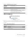
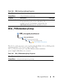
CIM_CoolingDevice
CIM_ManagedSystemElement
CIM_LogicalElement
CIM_LogicalDevice
CIM_CoolingDevice
The CIM_CoolingDevice class described in Table 3-19 contains a set of
devices that work to keep the ambient internal temperature of the system at a
safe value.
Table 3-19.
CIM_CoolingDevice Properties
Class Name:
CIM_CoolingDevice
Parent Class:
CIM_LogicalDevice
Property
Description
Data Type
ActiveCooling Specifies whether the device provides active (as opposed Boolean
to passive) cooling.
CIM_LogicalElement
57
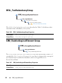
CIM_Fan
CIM_ManagedSystemElement
CIM_LogicalElement
CIM_LogicalDevice
CIM_CoolingDevice
CIM_Fan
The CIM_Fan class explained in Table 3-20 contains a set of devices that
work to keep the ambient internal temperature of the system at a safe value
by circulating air.
Table 3-20. CIM_Fan Properties
Class Name:
CIM_Fan
Parent Class:
CIM_CoolingDevice
Property
Description
Data
Type
VariableSpeed
Specifies whether the fan supports variable speeds.
Boolean
DesiredSpeed
Indicates the currently requested fan speed, defined in
RPM. When the value = TRUE, the fan supports
variable speeds. When a variable speed fan is supported
(VariableSpeed Boolean = TRUE), the actual speed is
determined using a sensor (CIM_Tachometer) that is
associated with the fan.
uint64
58
CIM_LogicalElement
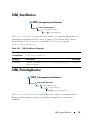
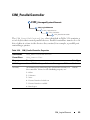
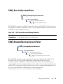
CIM_UserDevice
CIM_ManagedSystemElement
CIM_LogicalElement
CIM_LogicalDevice
CIM_UserDevice
The CIM_UserDevice class shown in Table 3-21 contains logical devices
that allow a computer system’s users to input, view, or hear data. Classes
derived from CIM_UserDevice include CIM_Keyboard and
CIM_PointingDevice.
Table 3-21.
CIM_UserDevice Properties
Class Name:
CIM_UserDevice
Parent Class:
CIM_LogicalDevice
Property
Description
Data Type
IsLocked
Indicates whether the device is locked, preventing user
input or output.
Boolean
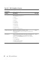
CIM_PointingDevice
CIM_ManagedSystemElement
CIM_LogicalElement
CIM_LogicalDevice
CIM_UserDevice
CIM_PointingDevice
The CIM_PointingDevice class described in Table 3-22 includes those
devices used to point to regions of a display. Examples are a mouse or a
trackball.
CIM_LogicalElement
59
Table 3-22. CIM_PointingDevice Properties
Class Name:
CIM_PointingDevice
Parent Class:
CIM_UserDevice
Property
Description
Data Type
PointingType
Indicates the type of pointing device. Values for the
PointingType property are:
uint16
1 - Other
2 - Unknown
3 - Mouse
4 - Trackball
5 - Trackpoint
6 - Glidepoint
7 - Touch pad
8 - Touch screen
9 - Mouse—optical sensor
NumberOfButtons Indicates the number of buttons. If the
CIM_PointingDevice has no buttons, a value of 0
is returned.
Handedness
Integer indicating whether the CIM_PointingDevice uint16
is configured for right- or left-handed operation.
Values for the Handedness property are as follows:
0 - Unknown
1 - Not applicable
2 - Right-handed operation
3 - Left-handed operation
60
uint8
CIM_LogicalElement
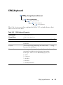
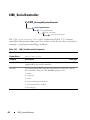
CIM_Keyboard
CIM_ManagedSystemElement
CIM_LogicalElement
CIM_LogicalDevice
CIM_UserDevice
CIM_Keyboard
The CIM_Keyboard class explained in Table 3-23 includes devices that
allow users to enter data.
Table 3-23.
CIM_Keyboard Properties
Class Name:
CIM_Keyboard
Parent Class:
CIM_UserDevice
Property
Description
Data Type
NumberOfFunctionKeys Indicates the number of function keys on the
keyboard.
uint16
Layout
A free-form string indicating the format and
layout of the keyboard.
string
Password
An integer indicating whether a hardware-level uint16
password is enabled at the keyboard, preventing
local input. Values for the Password property are:
1 - Other
2 - Unknown
3 - Disabled
4 - Enabled
5 - Not implemented
CIM_LogicalElement
61
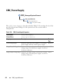
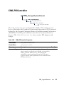
CIM_PowerSupply
CIM_ManagedSystemElement
CIM_LogicalElement
CIM_LogicalDevice
CIM_PowerSupply
The CIM_PowerSupply class described in Table 3-24 contains devices that
provide current and voltage for the operation of the system and its
components.
Table 3-24. CIM_PowerSupply Properties
Class Name:
CIM_PowerSupply
Parent Class:
CIM_LogicalDevice
Property
Description
Data
Type
IsSwitchingSupply
Indicates that the power supply is a switching
power supply and not a linear power supply.
Boolean
Range1InputVoltageLow Indicates the low voltage in millivolts of input uint32
voltage range 1 for this power supply. A value of
0 denotes unknown.
Range1InputVoltageHigh Indicates the high voltage in millivolts of input uint32
voltage range 1 for this power supply. A value of
0 denotes unknown.
62
CIM_LogicalElement
Table 3-24.
CIM_PowerSupply Properties (continued)
Class Name:
CIM_PowerSupply
Parent Class:
CIM_LogicalDevice
Property
Description
ActiveInputVoltage
Indicates which input voltage range is currently uint16
in use. Range 1, 2, or both can be specified
using the values 3, 4, or 5, respectively. If the
supply is not drawing power, a value of 6
(neither) can be specified. This information is
necessary in the case of an uninterruptible
power supply (UPS), a subclass of power supply.
Values for the ActiveInputVoltage property are:
Data
Type
1 - Other
2 - Unknown
3 - Range 1
4 - Range 2
5 - Both range 1 and range 2
6 - Neither range 1 nor range 2
TotalOutputPower
Represents the total output power of the power uint32
supply in milliwatts. A value of 0 denotes that
the power output is unknown.
PMCapable
Indicates the Power Monitoring capability.
CIM_LogicalElement
Boolean
63
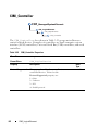
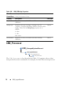
CIM_Controller
CIM_ManagedSystemElement
CIM_LogicalElement
CIM_LogicalDevice
CIM_Controller
The CIM_Controller class shown in Table 3-25 groups miscellaneous
control-related devices. Examples of controllers are small computer system
interface (SCSI) controllers, Universal Serial Bus (USB) controllers, and serial
controllers.
Table 3-25. CIM_Controller Properties
Class Name:
CIM_Controller
Parent Class:
CIM_LogicalDevice
Property
Description
Data
Type
ProtocolSupported
The protocol used by the controller to access
controlled devices. Values for the
ProtocolSupported property are:
uint16
1 - Other
2 - Unknown
3 - PCI
4 - Parallel protocol
64
CIM_LogicalElement
CIM_ParallelController
CIM_ManagedSystemElement
CIM_LogicalElement
CIM_LogicalDevice
CIM_Controller
CIM_ParallelController
The CIM_ParallelController class identified in Table 3-26 contains a
set of objects that control parallel devices. Parallel controllers transfer 8 or 16
bits of data at a time to the devices they control, for example, a parallel port
controlling a printer.
Table 3-26.
CIM_ParallelController Properties
Class Name:
CIM_ParallelController
Parent Class:
CIM_Controller
Property
Description
Data Type
DMASupport
Set to TRUE if the parallel controller supports DMA.
Boolean
Security
An enumeration indicating the operational security for
the controller. Values for the Security property are:
uint16
1 - Other
2 - Unknown
3 - None
4 - External interface locked out
5 - External interface enabled
6 - Boot bypass
CIM_LogicalElement
65
CIM_SerialController
CIM_ManagedSystemElement
CIM_LogicalElement
CIM_LogicalDevice
CIM_Controller
CIM_SerialController
The CIM_SerialController class explained in Table 3-27 contains
controllers that transfer data one bit at a time to the devices they control, for
example, a serial port controlling a modem.
Table 3-27. CIM_SerialController Properties
Class Name:
CIM_SerialController
Parent Class:
CIM_Controller
Property
Description
Data Type
MaxBaudRate
Indicates the maximum baud rate in bits per second
supported by the serial controller.
uint32
Security
An enumeration indicating the operational security for uint16
the controller. Values for the Security property are:
1 - Other
2 - Unknown
3 - None
4 - External interface locked out
5 - External interface enabled
6 - Boot bypass
66
CIM_LogicalElement
CIM_PCIController
CIM_ManagedSystemElement
CIM_LogicalElement
CIM_LogicalDevice
CIM_Controller
CIM_PCIController
The CIM_PCIController class listed in Table 3-28 contains a set of
devices that follow the Peripheral Component Interconnect (PCI) protocol
defined by the Personal Computer Memory Card International Association
(PCMCIA). The PCI protocol defines how data is transferred between
devices. The CIM_PCIController class contains PCI adapters and
bridges.
Table 3-28.
CIM_PCIController Properties
Class Name:
CIM_PCIController
Parent Class:
CIM_Controller
Property
Description
Data Type
CommandRegister The current contents of the register that provide
uint16
basic control over the device’s ability to respond to,
and/or perform PCI accesses. The data in the
capabilities array is gathered from the PCI status
register and the PCI capabilities list as defined in the
PCI specification.
CIM_LogicalElement
67
Table 3-28. CIM_PCIController Properties (continued)
Class Name:
CIM_PCIController
Parent Class:
CIM_Controller
Property
Description
Data Type
Values for the CommandRegister property are:
0 - Unknown
1 - Other
2 - Supports 66 MHz
3 - Supports user-definable features
4 - Supports fast back-to-back transactions
5 - PCI-X capable
6 - PCI power management supported
7 - Message signaled interrupts supported
8 - Parity error recovery capable
9 - AGP supported
10 - Vital product data supported
11 - Provides slot identification
12 - Hot swap supported
CIM_PCIDevice
CIM_ManagedSystemElement
CIM_LogicalElement
CIM_LogicalDevice
CIM_Controller
CIM_PCIController
CIM_PCIDevice
The CIM_PCIDevice class shown in Table 3-29 describes the capabilities
and management of a PCI device controller on an adapter card.
68
CIM_LogicalElement
Table 3-29.
CIM_PCIDevice Properties
Class Name:
CIM_PCIDevice
Parent Class:
CIM_PCIController
Property
Description
Data Type
BaseAddress
Identifies an array of up to six doubleword base memory addresses.
uint32
SubsystemID
Identifies a subsystem identifier code.
uint16
SubsystemVendorID
Identifies a subsystem vendor ID. ID
uint16
information is reported from a PCI device
via protocol-specific requests. This
information is also present in the
CIM_PhysicalElement class (the
manufacturer property) for hardware, and
the CIM_Product class (the vendor
property) for information related to
product acquisition.
ExpansionROMBaseAddress Identifies a double-word expansion ROM uint32
base memory address.
CIM_PCIBridge
CIM_ManagedSystemElement
CIM_LogicalElement
CIM_LogicalDevice
CIM_Controller
CIM_PCIController
CIM_PCIBridge
The CIM_PCIBridge class shown in Table 3-30 describes the capabilities
and management of a PCI controller providing bridge-to-bridge capability. An
example is a PCI to Industry-Standard Architecture (ISA) bus bridge.
CIM_LogicalElement
69
Table 3-30. CIM_PCIBridge Properties
Class Name:
CIM_PCIBridge
Parent Class: CIM_PCIController
Property
Description
Data Type
BaseAddress
Identifies an array of double-word base memory
addresses.
uint32
BridgeType
Indicates the type of bridge. A bridge is PCI to
<value>, except for the Host, which is a host-to-PCI
bridge. Values for the BridgeType property are as
follows:
uint16
0 - Host
1 - ISA
128 - Other
BaseAddress
Identifies an array of double-word base memory
addresses.
uint32
CIM_Processor
CIM_ManagedSystemElement
CIM_LogicalElement
CIM_LogicalDevice
CIM_Processor
The CIM_Processor class described in Table 3-31 contains devices that
interpret and execute commands, for example, the Intel Xeon microprocessor.
70
CIM_LogicalElement
Table 3-31.
CIM_Processor Properties
Class Name:
CIM_Processor
Parent Class:
CIM_LogicalDevice
Property
Description
Role
A string describing the role of the microprocessor, for string
example, central microprocessor or math processor.
UpgradeMethod
Provides microprocessor socket information
uint16
including data on how this microprocessor can be
upgraded (if upgrades are supported). This property
is an integer enumeration. Values for the
UpgradeMethod property are as follows:
Data
Type
1 - Other
2 - Unknown
3 - Daughter board
4 - ZIF socket
5 - Replacement/piggy back
6 - None
7 - LIF socket
8 - Slot 1
9 - Slot 2
10 - 370-pin socket
19 - Socket mPGA604
20 - Socket LGA771
21 - Socket LGA775
22 - Socket S1
23 - Socket AM2
24- Socket F (1207)
25- Socket LGA1366
MaxClockSpeed
Indicates the maximum speed (in MHz) of this
microprocessor.
uint32
Core count
Indicates the number of core processors detected.
uint16
CoreEnabledCount Indicates the number of core processors enabled.
CIM_LogicalElement
uint16
71
Table 3-31. CIM_Processor Properties (continued)
Class Name:
CIM_Processor
Parent Class:
CIM_LogicalDevice
Property
Description
Data
Type
CurrentClockSpeed Indicates the current speed (in MHz) of this
microprocessor.
uint32
DataWidth
Indicates the processor data width in bits.
uint16
AddressWidth
Indicates the processor address width in bits.
uint16
Stepping
Indicates the revision level of the processor within
the microprocessor family.
string
UniqueID
Identifies a globally unique identifier for the
microprocessor. This identifier may only be unique
within a microprocessor family.
string
Brand
Indicates the brand name of the processor.
string
Model
Indicates the model name of the processor.
string
ExtendedCharacteri Indicates the extended capabilities of the processor. uint16
stics
This attribute is a bit field. The following are the
definitions of a bit when set to one:
Bit 0 — Virtualization Technology (VT) supported
Bit 1 — Demand-Based Switching (DBS) supported
Bit 2 — eXecute Disable (XD) supported
Bit 3 — Hyper Threading (HT) supported
72
CIM_LogicalElement
Table 3-31.
CIM_Processor Properties (continued)
Class Name:
CIM_Processor
Parent Class:
CIM_LogicalDevice
Property
Description
ExtendedStates
Indicates the setting of the extended capabilities of uint16
the processor. This attribute is a bit field. The
following are the definitions of a bit when set to one:
Data
Type
Bit 0 — Virtualization Technology (VT) enabled
Bit 1 — Demand-Based Switching (DBS) enabled
Bit 2 — eXecute Disable (XD) enabled
Bit 3 — Hyper Threading (HT) enabled
CPUStatus
uint16
Indicates the current status of the microprocessor.
For example, it may be disabled by the user through
the BIOS or disabled due to a POST error. Values for
the CPUStatus property are as follows:
0 - Unknown
1 - Microprocessor enabled
2 - Microprocessor disabled by user via BIOS setup
3 - Microprocessor disabled by BIOS (POST error)
4 - Microprocessor is idle
5 - Other
CIM_LogicalElement
73
Table 3-31. CIM_Processor Properties (continued)
Class Name:
CIM_Processor
Parent Class:
CIM_LogicalDevice
Property
Description
Data
Type
Family
Refers to the processor family type. Values for the
Family property are as follows:
uint16
1 - Other
2 - Unknown
3 - 8086
4 - 80286
5 - 80386
6 - 80486
7 - 8087
8 - 80287
9 - 80387
10 - 80487
11 - Pentium Brand
12 - Pentium Pro
13 - Pentium II
14 - Pentium processor with MMX technology
15 - Celeron
16 - Pentium II Xeon
17 - Pentium III
18 - M1 family
19 - M2 family
24 - AMD Duron Processor
25 - K5 family
26 - K6 family
27 - K6 -2
28 - K6-3
74
CIM_LogicalElement
Table 3-31.
CIM_Processor Properties (continued)
Class Name:
CIM_Processor
Parent Class:
CIM_LogicalDevice
Property
Description
Family (continued)
29 - AMD Athlon Processor Family
Data
Type
30 - AMD29000 Family
31 - K6-2+
32 - Power PC Family
33 - Power PC 601
34 - Power PC 603
35 - Power PC 603+
36 - Power PC 604
37 - Power PC 620
38 - Power PC X704
39 - Power PC 750
40 - Intel Core Duo processor
41 - Intel Core Duo mobile processor
42 - Intel Core Solo mobile processor
43 - Intel Atom processor
48 - Alpha Family
49 - Alpha 21064
50 - Alpha 21066
51 - Alpha 21164
52 - Alpha 21164PC
53 - Alpha 21164a
54 - Alpha 21264
55 - Alpha 21364
60 - AMD Opteron 4100 Series Processor
64 - MIPS Family
65 - MIPS R4000
66 - MIPS R4200
67 - MIPSR4400
68 - MIPS R4600
CIM_LogicalElement
75
Table 3-31. CIM_Processor Properties (continued)
Class Name:
CIM_Processor
Parent Class:
CIM_LogicalDevice
Property
Description
Family (continued)
69 - MIPS R10000
80 - SPARC Family
81 - SuperSPARC
82 - microSPARC II
83 - microSPARC IIep
84 - UltraSPARC
85 - UltraSPARC II
86 - UltraSPARC IIi
87 - UltraSPARC III
88 - UltraSPARC IIIi
96 - 68040
97 - 68xxx Family
98 - 68000
99 - 68010
100 - 68020
101 - 68030
112 - Hobbit family
120 - Crusoe 5000 Family
121 - Crusoe 3000 Family
122 - Efficeon 8000 Family
128 - Weitek
130 - Itanium Processor
131 - AMD Athlon 64 Processor Family
132 - AMD Opteron Processor Family
133 - AMD Sempron Processor Family
134 - AMD Turion 64 Mobile Technology
135 - Dual-Core AMD Opteron Processor family
136 - AMD Athlon 64 X2 Dual-Core Processor family
76
CIM_LogicalElement
Data
Type
Table 3-31.
CIM_Processor Properties (continued)
Class Name:
CIM_Processor
Parent Class:
CIM_LogicalDevice
Property
Description
Family (continued)
137 - AMD Turion 64 X2 Mobile Technology
Data
Type
138 - Quad-Core AMD Opteron Processor Family
139 - Third-Generation AMD Opteron Processor Family
140 - AMD Phenom FX Quad-Core Processor Family
141 - AMD Phenom X4 Quad-Core Processor Family
142 - AMD Phenom X2 Dual-Core Processor Family
143 - AMD Athlon X2 Dual-Core Processor Family
144 - PA-RISC family
145 - PA-RISC 8500
146 - PA-RISC 8000
147 - PA-RISC 7300LC
148 - PA-RISC 7200
149 - PA-RISC 7100LC
150 - PA-RISC 7100
160 - V30 family
161 - Quad-Core Intel Xeon processor 3200 Series
162 - Dual-Core Intel Xeon processor 3000 Series
163 - Quad-Core Intel Xeon processor 5300 Series
164 - Dual-Core Intel Xeon processor 5100 Series
165 - Dual-Core Intel Xeon processor 5000 Series
166 - Dual-Core Intel Xeon processor LV
167 - Dual-Core Intel Xeon processor ULV
168 - Dual-Core Intel Xeon processor 7100 Series
169 - Quad-Core Intel Xeon processor 5400 Series
170 - Quad-Core Intel Xeon processor
171- Dual-Core Intel Xeon processor 5200 Series
172- Dual-Core Intel Xeon processor 7200 Series
173- Quad-Core Intel Xeon processor 7300 Series
CIM_LogicalElement
77
Table 3-31. CIM_Processor Properties (continued)
Class Name:
CIM_Processor
Parent Class:
CIM_LogicalDevice
Property
Description
Family (continued)
174- Quad-Core Intel Xeon processor 7400 Series
175- Multi-Core Intel Xeon processor 7400 Series
176 - Pentium III Xeon
177 - Pentium III Processor with Intel SpeedStep
178 - Technology
179 - Pentium 4
180 - Intel Xeon
181 - AS400 Family
182 - Intel Xeon Processor MP
183 - AMD Athlon XP family
184 - AMD Athlon MP family
185 - Intel Itanium 2
186 - Intel Pentium M processor
187 - Intel Celeron D Processor
188 - Intel Pentium D Processor
189 - Intel Pentium Extreme Edition processor
190 - Intel Core 2 processor
192 - Intel Core 2 Solo processor
193 - Intel Core 2 Extreme processor
194 - Intel Core 2 Quad processor
195 - Intel Core 2 Extreme mobile processor
196 - Intel Core 2 Duo mobile processor
197 - Intel Core 2 Solo mobile processor
198 - Intel Core i7 Processor
199 - Dual-Core Intel Celeron Processor
200 - S/390 and zSeries family
201 - ESA/390 G4
202 - ESA/390 G5
78
CIM_LogicalElement
Data
Type
Table 3-31.
CIM_Processor Properties (continued)
Class Name:
CIM_Processor
Parent Class:
CIM_LogicalDevice
Property
Description
Family (continued)
203 - ESA/390 G6
Data
Type
204 - z/Architecture base
206 - CEh 206 Intel Core i3 processor
214 - Multi-Core Intel Xeon processor
215 - Dual-Core Intel Xeon processor 3xxx Series
216 - Quad-Core Intel Xeon processor 3xxx Series
217 - D9h 217 VIA Nano Processor Family
218 - Dual-Core Intel Xeon processor 5xxx Series
219 - Quad-Core Intel Xeon processor 5xxx Series
221 - Dual-Core Intel Xeon processor 7xxx Series
222 - Quad-Core Intel Xeon processor 7xxx Series
223 - Multi-Core Intel Xeon processor 7xxx Series
224 - E0h 224 Multi-Core Intel Xeon processor 3400
Series
230 - Embedded AMD Opteron Quad-Core Processor Family
231 - AMD Phenom Triple-Core Processor Family
232 - AMD Turion Ultra Dual-Core Mobile Processor Family
233 - AMD Turion Dual-Core Mobile Processor Family
234 - AMD Athlon Dual-Core Processor Family
235 - AMD Sempron SI Processor Family
238 - AMD Opteron Six-Core Processor Family
250 - i860
251 - i960
260 - SH-3
261 - SH-4
280 - ARM
281 - StrongARM
CIM_LogicalElement
79
Table 3-31. CIM_Processor Properties (continued)
Class Name:
CIM_Processor
Parent Class:
CIM_LogicalDevice
Property
Description
Family (continued)
300 - 6x86
Data
Type
301 - MediaGX
302 - MII
320 - WinChip
350 - DSP
500 - Video processor
CIM_StorageExtent
CIM_ManagedSystemElement
CIM_LogicalElement
CIM_LogicalDevice
CIM_StorageExtent
CIM_StorageExtent identified in Table 3-32 contains devices that
manage data storage, for example, hard drives or microprocessor memory.
Table 3-32. CIM_StorageExtent Properties
Class Name:
CIM_StorageExtent
Parent Class:
CIM_LogicalDevice
80
CIM_LogicalElement
CIM_Memory
CIM_ManagedSystemElement
CIM_LogicalElement
CIM_LogicalDevice
CIM_StorageExtent
CIM_Memory
The CIM_Memory class identified in Table 3-33 describes the capabilities
and management of storage extent devices, for example, cache memory or
system memory.
Table 3-33.
CIM_Memory Properties
Class Name:
CIM_Memory
Parent Class:
CIM_StorageExtent
CIM_CacheMemory
CIM_ManagedSystemElement
CIM_LogicalElement
CIM_LogicalDevice
CIM_StorageExtent
CIM_Memory
CIM_CacheMemory
The CIM_CacheMemory class explained in Table 3-34 describes the capabilities
and management of cache memory. Cache memory allows a microprocessor to
access data and instructions faster than normal system memory.
CIM_LogicalElement
81
Table 3-34. CIM_CacheMemory Properties
Class Name:
CIM_CacheMemory
Parent Class: CIM_Memory
Property
Description
Data Type
Level
Defines whether this is the primary, secondary, or
tertiary cache. Values for the Level property are as
follows:
uint16
1 - Other
2 - Unknown
3 - Primary
4 - Secondary
5 - Tertiary
6 - Not applicable
WritePolicy
Either defines whether this cache is a write-back or
uint16
write-through cache or whether this information varies
with address or is defined individually for each
input/output (I/O). Values for the WritePolicy
property are as follows:
1 - Other
2 - Unknown
3 - Write-back
4 - Write-through
5 - Varies with address
6 - Determination per I/O
CacheType
Defines whether this cache is for instruction caching, uint16
data caching, or both (unified). Values for the
CacheType property are as follows:
1 - Other
2 - Unknown
3 - Instruction
4 - Data
5 - Unified
82
CIM_LogicalElement
Table 3-34.
Class Name:
CIM_CacheMemory Properties (continued)
CIM_CacheMemory
Parent Class: CIM_Memory
Property
Description
Data Type
LineSize
Indicates the size, in bytes, of a single cache bucket or uint32
line.
ReadPolicy
Defines the policy used by the cache for handling read uint16
requests. Values for the ReadPolicy property are as
follows:
1 - Other
2 - Unknown
3 - Read
4 - Read-ahead
5 - Read and read-ahead
6 - Determination per I/O
CIM_SoftwareElement
CIM_ManagedSystemElement
CIM_LogicalElement
CIM_SoftwareElement
The CIM_SoftwareElement class described in Table 3-35 is used to define
CIM_SoftwareFeature. The CIM_SoftwareElement class consists of
individually manageable or deployable parts for a particular platform. A software
element’s platform is uniquely identified by its underlying hardware architecture
and operating system (for example, a system running Microsoft Windows NT on
an Intel microprocessor). A software element’s implementation on a particular
platform depends on the platform’s operating system.
CIM_LogicalElement
83
Table 3-35. CIM_SoftwareElement Properties
Class Name:
CIM_SoftwareElement
Parent Class:
CIM_LogicalElement
Property
Description
Data
Type
Name
Indicates the name that identifies this software
element.
string
Version
Provides the version in the form
<major>.<minor>.<revision> or
<major>.<minor><letter><revision>;
for example, 1.2.3 or 1.2a3.
string
Manufacturer
See Table 1-1.
string
BuildNumber
Indicates the internal identifier for this build of
the software element.
string
IdentificationCode
Provides the manufacturer’s identifier for this
software element. Often this will be a stock
keeping unit (SKU) or a part number.
string
84
CIM_LogicalElement
Table 3-35.
CIM_SoftwareElement Properties (continued)
Class Name:
CIM_SoftwareElement
Parent Class:
CIM_LogicalElement
Property
Description
Data
Type
SoftwareElementType Indicates the type of software element. Values for uint16
SoftwareElementType are:
1 - Other
2 - Unknown
3 - BIOS
4 - ESM
5 - PSPB
6 - System Backplane
7 - Hendrix (PV20x) Kernel
8 - Hendrix (PV20x) Application
9 - Front Panel
10 - BMC
11 - Hot Plug PCI
12 - SDR
13 - Peripheral Bay Backplane
14 - Slimfast Secondary Backplane
15 - Generic Secondary Backplane (ESM 3&4)
16 - RAC4
17 - iDRAC
CIM_LogicalElement
85
CIM_BIOSElement
CIM_ManagedSystemElement
CIM_LogicalElement
CIM_SoftwareElement
CIM_BIOSElement
The CIM_BIOSElement class listed in Table 3-36 describes the BIOS for
the system. The BIOS controls the following:
•
Communications between the microprocessor and peripheral devices,
such as the keyboard and the video adapter
•
Miscellaneous functions, such as system messages
Table 3-36. CIM_BIOSElement Properties
Class Name:
CIM_BIOSElement
Parent Class:
CIM_SoftwareElement
Property
Description
Data Type
Version
Provides the product version information.
string
Manufacturer
See Table 1-1
string
PrimaryBIOS
Specifies whether a given BIOS is the primary BIOS for the Boolean
system. When the value = TRUE, the BIOS is the
primary BIOS.
86
CIM_LogicalElement
CIM_SoftwareFeature
CIM_ManagedSystemElement
CIM_LogicalElement
CIM_SoftwareFeature
The CIM_SoftwareFeature class shown in Table 3-37 defines a particular
function or capability of a product or application system. This class is
intended to be meaningful to a consumer, or user of a product, rather than to
explain how the product is built or packaged. When a software feature can
exist on multiple platforms or operating systems (for example, a client
component of a three-tiered client/server application might run on
Windows NT), a software feature is a collection of all the software elements
for these different platforms. The users of the model must be aware of this
situation because typically they will be interested in a sub-collection of the
software elements required for a particular platform.
Table 3-37.
CIM_SoftwareFeature Properties
Class Name:
CIM_SoftwareFeature
Parent Class:
CIM_LogicalElement
Property
Description
Data Type
IdentifyingNumber Provides product identification such as a serial
number on software.
string
ProductName
Identifies the commonly used product name.
string
Vendor
Identifies the name of the product’s supplier.
Corresponds to the vendor property in the product
object in the DMTF solution exchange standard.
string
Version
Identifies the product version information.
Corresponds to the version property in the product
object in the DMTF solution exchange standard.
string
Name
Defines the label by which the object is known to the string
users. This label is a user-defined name that uniquely
identifies the element.
CIM_LogicalElement
87
DELL_SoftwareFeature
CIM_ManagedSystemElement
CIM_LogicalElement
CIM_SoftwareFeature
DELL_SoftwareFeature
DELL_SoftwareFeature described in Table 3-38 defines the universal
resource locator (URL) of the systems management software and the
language in which systems management information displays. Defining these
properties enables users to manage a system using an Internet browser. You
can access Server Administrator using the secure hypertext transfer protocol
(https) and a preassigned port number of 1311, or you can specify a port
number of your own choice.
Table 3-38. DELL_SoftwareFeature Properties
Class Name:
DELL_SoftwareFeature
Parent Class:
CIM_SoftwareFeature
Property
Description
Data Type
OmsaURL
Defines the URL for Server Administrator.
string
Language
Sets the language for systems management information.
string
AgentVersion Defines the version information of local CIM agent (same string
as ISVC version.)
CIM_SystemResource
CIM_ManagedSystemElement
CIM_LogicalElement
CIM_SystemResource
88
CIM_LogicalElement
The CIM_SystemResource class listed in Table 3-39 provides access to
system resources from an operating system. SystemResources consist of
interrupt requests (IRQs) and direct memory access (DMA) capabilities.
Table 3-39.
CIM_SystemResource Properties
Class Name:
CIM_SystemResource
Parent Class:
CIM_LogicalElement
CIM_IRQ
CIM_ManagedSystemElement
CIM_LogicalElement
CIM_SystemResource
CIM_IRQ
The CIM_IRQ class described in Table 3-40 contains IRQ information. An
IRQ is a signal that data is about to be sent to or received by a peripheral
device. The signal travels by an IRQ line to the microprocessor. Each
peripheral connection must be assigned an IRQ number. For example, the
first serial port in your computer (COM1) is assigned to IRQ4 by default.
Table 3-40.
CIM_IRQ Properties
Class Name:
CIM_IRQ
Parent Class:
CIM_SystemResource
Property
Description
Data Type
CSCreationClassName See Table 1-1.
string
CSName
See Table 1-1.
string
CreationClassName
See Table 1-1.
string
IRQNumber
Identifies the interrupt request number.
uint32
CIM_LogicalElement
89
Table 3-40. CIM_IRQ Properties (continued)
Class Name:
CIM_IRQ
Parent Class:
CIM_SystemResource
Property
Description
Data Type
Availability
Indicates the availability of the IRQ. Values for
the Availability property are as follows:
uint16
1 - Other
2 - Unknown
3 - Available
4 - In use/not available
5 - In use and available
TriggerLevel
Indicates whether the interrupt is triggered by
uint16
the hardware signal going high or low. Values for
the TriggerLevel property are as follows:
1 - Other
2 - Unknown
3 - Active low
4 - Active high
TriggerType
Indicates whether edge (value=4) or level
triggered (value=3) interrupts occur.
1 - Other
2 - Unknown
3 - Level
4 - Edge
90
CIM_LogicalElement
uint16
Table 3-40.
CIM_IRQ Properties (continued)
Class Name:
CIM_IRQ
Parent Class:
CIM_SystemResource
Property
Description
Data Type
Shareable
Indicates whether the IRQ can be shared.
A value of TRUE indicates that the IRQ can be
shared.
Boolean
Hardware
Indicates whether the interrupt is hardware- or Boolean
software-based. (A value of TRUE indicates that
the interrupt is hardware based.) On a personal
computer, a hardware IRQ is a physical wire to a
programmable interrupt controller (PIC) chip
set through which the microprocessor can be
notified of time critical events. Some IRQ lines
are reserved for standard devices such as the
keyboard, diskette drive, and the system clock.
A software interrupt is a programmatic
mechanism to allow an application to get the
attention of the processor.
CIM_MemoryMappedIO
CIM_ManagedSystemElement
CIM_LogicalElement
CIM_SystemResource
CIM_MemoryMappedIO
The CIM_MemoryMappedIO class explained in Table 3-41 addresses both
memory and port I/O resources for personal computer architecture memory
mapped I/O.
CIM_LogicalElement
91
Table 3-41. CIM_MemoryMappedIO Properties
Class Name:
CIM_MemoryMappedIO
Parent Class:
CIM_SystemResource
Property
Description
Data Type
CSCreationClassName See Table 1-1.
string
CSName
See Table 1-1.
string
CreationClassName
See Table 1-1.
string
StartingAddress
Identifies the starting address of memory
mapped I/O.
uint64
EndingAddress
Identifies the ending address of memory mapped uint64
I/O.
MappedResource
Indicates the type of memory mapped I/O.
uint16
MappedResource defines whether memory or
I/O is mapped, and for I/O, whether the mapping
is to a memory or a port space. Memory mapped
I/O values are as follows:
1 - Other
2 - Mapped memory
3 - I/O mapped to memory space
4 - I/O mapped to port space
CIM_DMA
CIM_ManagedSystemElement
CIM_LogicalElement
CIM_SystemResource
CIM_DMA
The CIM_DMA class explained in Table 3-42 contains DMA information.
A DMA channel allows certain types of data transfer between RAM and a
device to bypass the microprocessor.
92
CIM_LogicalElement
Table 3-42.
CIM_DMA Properties
Class Name:
CIM_DMA
Parent Class:
CIM_SystemResource
Property
Description
Data Type
CSCreationClassName See Table 1-1.
string
CSName
See Table 1-1.
string
CreationClassName
See Table 1-1.
string
DMAChannel
Identifies a part of the object’s key value,
the DMA channel number.
uint32
Availability
Indicates the availability of the DMA. Values for
the Availability property are as follows:
uint16
1 - Other
2 - Unknown
3 - Available
4 - In use/not available
5 - In use and available/shareable
CIM_RedundancyGroup
CIM_ManagedSystemElement
CIM_LogicalElement
CIM_RedundancyGroup
The CIM_RedundancyGroup class explained in Table 3-43 is a set of
components that provide more instances of a critical component than are
required for the system’s operation. The extra components are used in case of
critical component failure. For example, multiple power supplies allow a
working power supply to take over when another power supply has failed.
CIM_LogicalElement
93
Table 3-43. CIM_RedundancyGroup Properties
Class Name:
CIM_RedundancyGroup
Parent Class:
CIM_LogicalElement
Property
Description
Data Type
CreationClassName See Table 1-1
string
Name
string
Serves as the key for the redundancy group’s
instance in an enterprise environment.
RedundancyStatus Provides information on the state of the redundancy uint16
group. Values for the RedundancyStatus property
are as follows:
0 - Unknown
1 - Other
2 - Fully redundant. Fully redundant means that all of the
configured redundancy is still available.
3 - Degraded redundancy. Degraded redundancy means
that some failures have been experienced but some
reduced amount of redundancy is still available.
4 - Redundancy lost. Redundancy lost means that a
sufficient number of failures have occurred so that no
redundancy is available and the next failure experienced
will cause overall failure.
CIM_ExtraCapacityGroup
CIM_ManagedSystemElement
CIM_LogicalElement
CIM_RedundancyGroup
CIM_ExtraCapacityGroup
The CIM_ExtraCapacityGroup class explained in Table 3-44 applies to
systems that have more capability and components than are required for
normal operation, for example, systems that have extra fans or power supplies.
94
CIM_LogicalElement
Table 3-44.
CIM_ExtraCapacityGroup Properties
Class Name:
CIM_ExtraCapacityGroup
Parent Class:
CIM_RedundancyGroup
Property
Description
Data Type
MinNumberNeeded Specifies the smallest number of elements that must uint32
be operational in order to have redundancy. For
example, in an N+1 redundancy relationship, the
MinNumberNeeded property should be set to N.
DELL_PSRedundancyGroup
CIM_ManagedSystemElement
CIM_LogicalElement
CIM_RedundancyGroup
CIM_ExtraCapacityGroup
DELL_PSRedundancyGroup
The DELL_PSRedundancyGroup described in Table 3-45 is a Dell-specific
extension of the CIM_PowerSupply class. The
DELL_PSRedundancyGroup class defines what constitutes
power supply redundancy in a system.
Table 3-45.
DELL_PSRedundancyGroup Properties
Class Name:
DELL_PSRedundancyGroup
Parent Class:
CIM_ExtraCapacityGroup
CIM_LogicalElement
95
DELL_FanRedundancyGroup
CIM_ManagedSystemElement
CIM_LogicalElement
CIM_RedundancyGroup
CIM_ExtraCapacityGroup
DELL_FanRedundancyGroup
The DELL_FanRedundancyGroup described in Table 3-46 defines what
constitutes fan redundancy in a system.
Table 3-46. DELL_FanRedundancyGroup Properties
Class Name:
DELL_FanRedundancyGroup
Parent Class:
CIM_ExtraCapacityGroup
CIM_EnabledLogicalElement Group
CIM_ManagedSystemElement
CIM_LogicalElement
CIM_EnabledLogicalElement
The CIM_EnabledLogicalElementGroup class described in Table 3-47
extends the CIM_LogicalElementGroup class to abstract the concept of
an element that is enabled or disabled, such as a LogicalDevice or
ServiceAccessPoint.
Table 3-47. CIM_EnabledLogicalElementGroup Properties
Class Name:
CIM_EnabledLogicalElementGroup
Parent Class:
CIM_LogicalElementGroup
96
CIM_LogicalElement
CIM_ServiceAccessPoint
CIM_ManagedSystemElement
CIM_LogicalElement
CIM_EnabledLogicalElement
CIM_ServiceAccessPoint
The CIM_ServiceAccessPointGroup class described in Table 3-48 represents
the ability to utilize or invoke a service. Access points indicate that a service is
available to other entities for use.
Table 3-48.
CIM_ServiceAccessPointGroup Properties
Class Name:
CIM_ServiceAccessPointGroup
Parent Class:
CIM_EnabledLogicalElement
CIM_RemoteServiceAccessPoint
CIM_ManagedSystemElement
CIM_LogicalElement
CIM_EnabledLogicalElement
CIM_ServiceAccessPoint
CIM_RemoteServiceAccessPoint
The CIM_RemoteServiceAccessPointGroup class identified in Table 3-49
describes the accessing and addressing of information for a remote
connection that is known to a local network element. This information is
contained in the local network element since this is the context in which it is
remote. The relevance of the remote service access point and information on
its use are described by subclassing or associating to the
CIM_RemoteServiceAccessPointGroup class.
CIM_LogicalElement
97
Table 3-49. CIM_RemoteServiceAccessPointGroup Properties
Class Name:
CIM_RemoteServiceAccessPointGroup
Parent Class:
CIM_ServiceAccessPointGroup
Property
Description
AccessInfo
Describes accessing or addressing of information for a string
remote connection. This can be a host name, network
address, and other similar information.
InfoFormat
Indicates an enumerated integer describing the format uint16
and interpretation of the AccessInfo property.
This property can have the following values:
1 - Other
2 - Host Name
3 - Ipv4 Address
4 - Ipv6 Address
5 - IPX Address
6 - DECnet Address
7 - SNA Address
8 - Autonomous System Number
9 - MPLS Label
10..99 - DMTF Reserved
100 - Dial String
101 - Ethernet Address
102 - Token Ring Address
103 - ATM Address
104 - Frame Relay Address
105..199 - DMTF Reserved
200 - URL
32768..65535 - Vendor Specific
98
CIM_LogicalElement
Data Type
DELL_RemoteServiceAccessPort
CIM_ManagedSystemElement
CIM_LogicalElement
CIM_EnabledLogicalElement
CIM_ServiceAccessPoint
CIM_RemoteServiceAccessPoint
DELL_RemoteServiceAccessPort
The DELL_RemoteServiceAccessPortGroup class described in
Table 3-50 is an extended class of the CIM_RemoteServiceAccessPointGroup
class. The DELL_RemoteServiceAccessPortGroup class provides
information about Dell implementation-specific attributes.
Table 3-50.
DELL_RemoteServiceAccessPortGroup Properties
Class Name:
DELL_RemoteServiceAccessPortGroup
Parent Class:
CIM_RemoteServiceAccessPointGroup
Property
Description
Data Type
PortName
Displays the name of the service access port.
string
VersionString
Indicates the version of the access point service.
string
RemoteAccessType Indicated the type of remote access service. This
property can have the following values:
uint16
0 - BMC
8 - IMC
9 - CMC
10 - iDRAC6
11 - iDRAC6 for modular systems
13 - BMC
CIM_LogicalElement
99
DCIM_OEM_DataAccessModule
The DCIM_OEM_DataAccessModule class is derived from the
CIM_ManagedElement class. This class models hardware information in a
proprietary format.
Table 3-51. DCIM_OEM_DataAccessModule Properties
Class Name: DCIM_OEM_DataAccessModule
Parent Class: CIM_ManagedElement
Property
Description
Data Type
InstanceID
Identifies the instance.
string
GlobalStatus Represents the global health status of the sint32
system. This property can have the
following values:
0 - Other
1 - Unknown
2 - OK
3 - Warning / Non-Critical
4 - Critical
5 - Non-Recoverable
.. - Reserved
SendCmd
100
The SendCmd method is used to invoke string
proprietary hardware management
operation.
CIM_LogicalElement
DCIM_RegisteredProfile
The DCIM_RegisteredProfile class is derived from the
CIM_RegisteredProfile class. This class advertises the capabilities of
DCIM_OEM_DataAccessModule.
CIM_LogicalElement
101
102
CIM_LogicalElement
4
Dell-Defined Classes
The Dell-defined classes are defined and populated by Dell rather than by
CIM. None of these classes have a parent class and are on the same level as
CIM_ManagedSystemElement. For information on how the logs are
formatted, see Table 2-5.
Figure 4-1. Dell_EsmLog
CIM_ManagedSystemElement
DELL_EsmLog
The DELL_EsmLog class described in Table 4-1 records failure threshold
violations collected by Server Administrator’s embedded server management
(ESM) capabilities.
Table 4-1. DELL_EsmLog Properties
Class Name:
DELL_EsmLog
Parent Class:
None
Property
Description
Data
Type
recordNumber Provides an index to the ESM table.
uint32
logRecord
Provides the ESM message content.
string
eventTime
Indicates the time that the message is generated.
datetime
status
Indicates the severity of the event that caused the log string
to be generated.
Dell-Defined Classes
103
DELL_PostLog
CIM_ManagedSystemElement
DELL_PostLog
The DELL_PostLog identified in Table 4-2 is a record of the system’s
power-on self-test (POST). When you turn on a system, the POST tests
various system components, such as random-access memory (RAM),
the hard drives, and the keyboard.
Table 4-2. DELL_PostLog Properties
Class Name:
DELL_PostLog
Parent Class:
None
DELL_CMApplication
NOTE: Dell-updateable components, such as BIOS and firmware, are considered
applications.
CIM_ManagedSystemElement
DELL_CMApplication
The DELL_CMApplication class identified in Table 4-3 contains
information related to the Dell change management applications.
104
Dell-Defined Classes
Table 4-3. DELL_CMApplication Properties
Class Name:
DELL_CMApplication
Parent Class:
None
Property
Description
Data
Type
componentType
Defines the application type
string
subComponentID
Defines an application string
string
version
Indicates the current version of the application
string
name
Indicates the name of the application
string
deviceKey
Indicates the device key of the application
string
DELL_CMDevice
CIM_ManagedSystemElement
DELL_CMDevice
The DELL_CMDevice identified in Table 4-4 contains information related
to the Dell change management device.
Table 4-4. DELL_CMDevice Properties
Class Name:
DELL_CMDevice
Parent Class:
None
Property
Description
Data
Type
componentID
Defines a component string
string
name
Indicates the name of the device
string
vendorID
Defines an ID for vendor supplying the device
string
Dell-Defined Classes
105
Table 4-4. DELL_CMDevice Properties (continued)
Class Name:
DELL_CMDevice
Parent Class:
None
Property
Description
Data
Type
subVendorID
Defines an ID for an additional vendor supplying
the device
string
deviceID
Indicates the ID of the device
string
subDeviceID
Indicates the ID for additional device
string
bus
Indicates the PCI bus number
string
device
Indicates the PCI device number
string
function
Indicates the PCI Function number
string
DELL_CMDeviceApplication
CIM_ManagedSystemElement
DELL_CMDeviceApplications
The DELL_CMDeviceApplication class identified in Table 4-5 contains
information related to the Dell change management association between the
device and application.
Table 4-5. DELL_CMDeviceApplication Properties
Class Name:
DELL_CMDeviceApplication
Parent Class:
None
Property
Description
Data Type
antecedent
Refers to the device
string
dependent
Refers to the application
string
106
Dell-Defined Classes
DELL_CMInventory
CIM_ManagedSystemElement
DELL_CMInventory
The DELL_CMInventory identified in Table 4-6 contains information
related to the Dell Change Management inventory.
Table 4-6. DELL _CMInventory Properties
Class Name:
DELL_CMInventory
Parent Class:
None
Property
Description
Data
Type
local
Indicates the locale of the system
string
schemaVersion
Indicates the Inventory schema implemented by the
system
string
systemID
Defines the System ID
string
DELL_CMOS
CIM_ManagedSystemElement
DELL_CMOS
The DELL_CMOS class identified in Table 4-7 contains information related to
the Dell change management operating system.
Dell-Defined Classes
107
Table 4-7. DELL_CMOS Properties
Class Name:
DELL_CMOS
Parent Class:
None
Property
Description
Data
Type
architecture
Indicates the architecture of the operating system
string
vendor
Indicates the vendor of the operating system
string
majorVersion
Indicates the major version of the operating system
string
minorVersion
Indicates the minor version of the operating system
string
spMajorVersion Indicates the current service pack number for the
operating system’s major version
string
spMinorVersion Indicates the current service pack number for the
operating system’s minor version
string
DELL_CMProductInfo
CIM_ManagedSystemElement
DELL_CMProductInfo
The DELL_CMProductInfo identified in Table 4-8 contains information
related to the Dell change management product.
108
Dell-Defined Classes
Table 4-8. DELL_CMProductInfo Properties
Class Name:
DELL_CMProductInfo
Parent Class:
None
Property
Description
Data
Type
name
Indicates the name of the product
string
description
Provides a short description of the product
string
vendor
Indicates the name of the product manufacturer
string
version
Indicates the current version number of the product
string
DELL_BIOSExtensions
The DELL_BIOSExtensions identified in Table 4-9 contains information
related to the specific extension of the data attributes on your system.
Table 4-9. DELL_BIOSExtensions Properties
Class Name:
DELL_BIOSExtensions
Parent Class:
CIM_ManagedSystemElement
Property
Description
Data
Type
systemBIOSCharacteristics
Indicates the characteristics of
BIOS on your system
uint64
systemBIOSCharacteristicsExt1
Indicates the specific extension of
the data attributes on your system
uint8
systemBIOSCharacteristicsExt2
Indicates the specific extension of
the data attributes on your system
uint8
Dell-Defined Classes
109
Management Object File For Change
Management
This section shows the Management Object File (MOF) invcim.mof.
#pragma classflags("forceupdate")
#pragma namespace("\\\\.\\Root\\CIMV2")
[Locale(1033) : ToInstance]
Instance of __Namespace
{
Name = "Dell";
};
#pragma namespace ("\\\\.\\Root\\CIMV2\\Dell")
//**************************************
//***Registers omprov Win32 Provider ***
//**************************************
instance of __Win32Provider as $P
{
Name = "omprov";
ClsId = "{EF6540AC-870F-445c-9401-10AAADB45CCF}";
HostingModel = "NetworkServiceHost";
};
instance of __InstanceProviderRegistration
{
Provider = $P;
SupportsGet = "TRUE";
SupportsPut = "FALSE";
SupportsDelete = "FALSE";
110
Dell-Defined Classes
SupportsEnumeration = "TRUE";
};
instance of __MethodProviderRegistration
{
Provider = $P;
};
//core.mof
//=====================================
// Using my own MOF instead of inheriting from existing MOFs, for rapid
prototyping.
// =====================================
[Dynamic, Provider ("omprov"),
Description("The Dell_CMDevice class contains all the information
related to the Dell Change Management Device.")
]
class Dell_CMDevice
{
[write (true), key: ToSubClass]
string componentID;
[write (true), key: ToSubClass]
string name;
[write (true), key: ToSubClass]
string vendorID;
[write (true), key: ToSubClass]
string deviceID;
[write (true), key: ToSubClass]
string subDeviceID;
Dell-Defined Classes
111
[write (true), key: ToSubClass]
string subVendorID;
[write (true), key: ToSubClass]
string bus;
[write (true), key: ToSubClass]
string device;
[write (true), key: ToSubClass]
string function;
};
[Dynamic, Provider ("omprov"),
Description("The Dell_CMInventory class contains all the information
related to the Dell Change Management Inventory.")
]
class Dell_CMInventory
{
[write (true), key: ToSubClass]
string local;
[write (true), key: ToSubClass]
string schemaVersion;
[write (true), key: ToSubClass]
string systemID;
};
[Dynamic, Provider ("omprov"),
Description("The Dell_CMProductInfo class contains all the
information related to the Dell Change Management Product.")
]
class Dell_CMProductInfo
112
Dell-Defined Classes
{
[write (true), key: ToSubClass]
string name;
[write (true), key: ToSubClass]
string description;
[write (true), key: ToSubClass]
string vendor;
[write (true), key: ToSubClass]
string version;
};
[Dynamic, Provider ("omprov"),
Description("The Dell_CMOS class contains all the information related to
the Dell Change Management operating system.")
]
class Dell_CMOS
{
[write (true), key: ToSubClass]
string vendor;
[write (true), key: ToSubClass]
string majorVersion;
[write (true), key: ToSubClass]
string minorVersion;
[write (true), key: ToSubClass]
string spMajorVersion;
[write (true), key: ToSubClass]
string spMinorVersion;
[write (true), key: ToSubClass]
string architecture;
Dell-Defined Classes
113
};
[Dynamic, Provider ("omprov"),
Description("The Dell_CMApplication class contains all the
information related to the Dell Change Management Application.")
]
class Dell_CMApplication
{
[write (true), key: ToSubClass]
string componentType;
[write (true), key: ToSubClass]
string subComponentID;
[write (true), key: ToSubClass]
string version;
[write (true), key: ToSubClass]
string name;
[write (true), key: ToSubClass]
string deviceKey;
};
[Association, Dynamic, Provider ("omprov"),
Description("The Dell_CMDeviceApplication class contains all the
information related to the Dell Change Management association between the
device and the application (1:n).")
]
class Dell_CMDeviceApplication
{
[key, Override ("Antecedent"),
Description ("The Device.")
]
114
Dell-Defined Classes
Dell_CMDevice REF Antecedent;
[key, Override ("Dependent"),
Description ("The Application")
]
Dell_CMApplication REF Dependent;
};
// =====
// end of file
// =====
Classes for Power Management
The new classes introduced for power management are:
// ==================================================
// DELL_PowerConsumptionAmpsSensor
// ==================================================
[Dynamic, Provider ("dccim32"),
Description (
"Monitors the power consumption")
]
class DELL_PowerConsumptionAmpsSensor :
CIM_NumericSensor
{
[Override("SensorType") ]
uint16 SensorType = 4;
[Override("BaseUnits") ]
uint16 BaseUnits = 6;
Dell-Defined Classes
115
[Override("UnitModifier") ]
sint32 UnitModifier = -1;
[Override("RateUnits") ]
uint16 RateUnits = 0;
[Override ("CurrentReading"),
// Override is used to define the MappingString
qualifier
MappingStrings {"MIF.DMTF|Electrical Current
Probe|001.5"}
]
sint32 CurrentReading;
[Override ("NominalReading"),
MappingStrings {"MIF.DMTF|Electrical Current
Probe|001.6"}
]
sint32 NominalReading;
[Override ("NormalMax"),
MappingStrings {"MIF.DMTF|Electrical Current
Probe|001.7"}
]
sint32 NormalMax;
116
Dell-Defined Classes
[Override ("NormalMin"),
MappingStrings {"MIF.DMTF|Electrical Current
Probe|001.8"}
]
sint32 NormalMin;
[Override ("MaxReadable"),
MappingStrings {"MIF.DMTF|Electrical Current
Probe|001.9"}
]
sint32 MaxReadable;
[Override ("MinReadable"),
MappingStrings {"MIF.DMTF|Electrical Current
Probe|001.10"}
]
sint32 MinReadable;
[Override ("Resolution"),
Units ("Tenths of MilliAmps"),
MappingStrings {"MIF.DMTF|Electrical Current
Probe|001.17"}
]
uint32 Resolution;
[Override ("Tolerance"),
MappingStrings {"MIF.DMTF|Electrical Current
Probe|001.18"}
Dell-Defined Classes
117
]
sint32 Tolerance;
[Override ("Accuracy"),
MappingStrings {"MIF.DMTF|Electrical Current
Probe|001.19"}
]
sint32 Accuracy;
[read, write,MappingStrings
{"MIF.DMTF|Electrical Current Probe|001.11"}
]
sint32 LowerThresholdNonCritical;
[read, write,MappingStrings
{"MIF.DMTF|Electrical Current Probe|001.12"}
]
sint32 UpperThresholdNonCritical;
[read,MappingStrings {"MIF.DMTF|Electrical
Current Probe|001.13"}
]
sint32 LowerThresholdCritical;
[Override ("UpperThresholdCritical"),
MappingStrings {"MIF.DMTF|Electrical Current
Probe|001.14"}
]
118
Dell-Defined Classes
sint32 UpperThresholdCritical;
[Override ("LowerThresholdFatal"),
MappingStrings {"MIF.DMTF|Electrical Current
Probe|001.15"}
]
sint32 LowerThresholdFatal;
[Override ("UpperThresholdFatal"),
MappingStrings {"MIF.DMTF|Electrical Current
Probe|001.16"}
]
sint32 UpperThresholdFatal;
};
// ==================================================
// DELL_PowerConsumptionWattsSensor
// ==================================================
[Dynamic, Provider ("dccim32"),
Description (
"Monitors the power consumption")
]
class DELL_PowerConsumptionWattsSensor :
CIM_NumericSensor
{
[Override("SensorType") ]
uint16 SensorType = 4;
Dell-Defined Classes
119
[Override("BaseUnits") ]
uint16 BaseUnits = 7;
[Override("UnitModifier") ]
sint32 UnitModifier = 0;
[Override("RateUnits") ]
uint16 RateUnits = 0;
[Override ("CurrentReading"),
// Override is used to define the MappingString
qualifier
MappingStrings {"MIF.DMTF|Electrical Current
Probe|001.5"}
]
sint32 CurrentReading;
[Override ("NominalReading"),
MappingStrings {"MIF.DMTF|Electrical Current
Probe|001.6"}
]
sint32 NominalReading;
[Override ("NormalMax"),
MappingStrings {"MIF.DMTF|Electrical Current
Probe|001.7"}
120
Dell-Defined Classes
]
sint32 NormalMax;
[Override ("NormalMin"),
MappingStrings {"MIF.DMTF|Electrical Current
Probe|001.8"}
]
sint32 NormalMin;
[Override ("MaxReadable"),
MappingStrings {"MIF.DMTF|Electrical Current
Probe|001.9"}
]
sint32 MaxReadable;
[Override ("MinReadable"),
MappingStrings {"MIF.DMTF|Electrical Current
Probe|001.10"}
]
sint32 MinReadable;
[Override ("Resolution"),
Units ("Tenths of MilliAmps"),
MappingStrings {"MIF.DMTF|Electrical Current
Probe|001.17"}
]
uint32 Resolution;
Dell-Defined Classes
121
[Override ("Tolerance"),
MappingStrings {"MIF.DMTF|Electrical Current
Probe|001.18"}
]
sint32 Tolerance;
[Override ("Accuracy"),
MappingStrings {"MIF.DMTF|Electrical Current
Probe|001.19"}
]
sint32 Accuracy;
[read, write,MappingStrings
{"MIF.DMTF|Electrical Current Probe|001.11"}
]
sint32 LowerThresholdNonCritical;
[read, write,MappingStrings
{"MIF.DMTF|Electrical Current Probe|001.12"}
]
sint32 UpperThresholdNonCritical;
[read,MappingStrings {"MIF.DMTF|Electrical
Current Probe|001.13"}
]
sint32 LowerThresholdCritical;
122
Dell-Defined Classes
[Override ("UpperThresholdCritical"),
MappingStrings {"MIF.DMTF|Electrical Current
Probe|001.14"}
]
sint32 UpperThresholdCritical;
[Override ("LowerThresholdFatal"),
MappingStrings {"MIF.DMTF|Electrical Current
Probe|001.15"}
]
sint32 LowerThresholdFatal;
[Override ("UpperThresholdFatal"),
MappingStrings {"MIF.DMTF|Electrical Current
Probe|001.16"}
]
sint32 UpperThresholdFatal;
};
// ==================================================
// DELL_PowerConsumptionData
// ==================================================
[Dynamic, Provider ("dccim32"), Description (
"Dell Power Consumption Data includes, but is not
limited to Cumulative power consumption from a start
time, and peak values registered during a time period.
")
]
Dell-Defined Classes
123
class DELL_PowerConsumptionData : CIM_LogicalDevice
{
[Description (
"total power consumed from a start time")
]
uint32 cumulativePowerReading;
[Description (
"The time from which the power reading is
accumulated")
]
datetime cprStartTime;
[Description (
"Peak amperage reading")
]
unint16 peakAmpReading;
[Description (
"The time from which the peak amp reading is being
monitored")
]
datetime parStartTime;
[Description (
"The time of the peak amp reading")
]
124
Dell-Defined Classes
datetime parTime;
[Description (
"Peak wattage reading")
]
unint16 peakWattReading;
[Description (
"The time from which the peak watt reading is
being monitored")
]
datetime pwrStartTime;
[Description (
"The time of the peak watt reading")
]
datetime pwrTime;
[Description (
"function to be used to reset the peak readings")
]
uint32 ResetCounters([IN]sint32 counter);
};
uint16 powerCapCapabilities;
[Description (
Dell-Defined Classes
125
"User configured power setting")
]
uint16 powerCapSetting;
[Description (
"Instantaneous headroom")
]
uint32 instHeadRoom;
[Description (
"Peak headroom")
]
uint32 peakHeadRoom;
[Description (
"function to be used to set the power budget")
]
// ==================================================
// DELL_AssociatedSupplyPCAmps
// ==================================================
[Association,
Description (
"A PowerConsumptionAmpsSensor associated with a
CIM_PowerSupply which is defined by this class.")
]
class DELL_AssociatedSupplyPCAmps : CIM_Dependency
126
Dell-Defined Classes
{
[Override ("Antecedent"),
Description ("The PowerSupply instance.")
]
CIM_PowerSupply REF Antecedent;
[Override ("Dependent"),
Description (
"The PowerConsumptionAmpsSensor associated with the
CIM_PowerSupply.")
]
DELL_PowerConsumptionAmpsSensor REF Dependent;
};
// ==================================================
// DELL_AssociatedSystemPCWatts
// ==================================================
[Association,
Description (
"A PowerConsumptionWattsSensor associated with
a DELL_System which is defined by this class.")
]
class DELL_AssociatedSystemPCWatts: CIM_Dependency
{
[Override ("Antecedent"),
Description ("The DELL_System instance.")
]
Dell-Defined Classes
127
DELL_System REF Antecedent;
[Override ("Dependent"),
Description (
"The PowerConsumptionWattsSensor associated with the
system.")
]
DELL_PowerConsumptionWattsSensor REF Dependent;
};
// ==================================================
// AssociatedSystemPCData
// ==================================================
[Association,
Description (
"A PowerConsumptionData associated with a
DELL_System which is defined by this class.")
]
class DELL_AssociatedSystemPCData: CIM_Dependency
{
[Override ("Antecedent"),
Description ("The DELL_System instance.")
]
DELL_System REF Antecedent;
[Override ("Dependent"),
Description (
128
Dell-Defined Classes
"The PowerConsumptionData associated with the
PowerSupply.")
]
DELL_PowerConsumptionData REF Dependent;
};
// ==================================================
//
DELL_BIOSSettings
// ==================================================
[Dynamic, Provider("dccim32"): ToInstance,
Description (
"This class defines properties used for setting
parameters in the DellSystem Management BIOS."),
DisplayName("BIOS Settings")]
class DELL_BIOSSettings : CIM_ManagedSystemElement
{
[key, read, Description(
"This property defines the instance ID of this
class."),
DisplayName("Dell Instance ID")]
uint32 DellInstanceID;
[read, Description (
"Enables or Disables the Trusted Platform Module
(TPM)."),
DisplayName("TPM Security"),
ValueMap{"0", "1", "2", "3", "4"},
Values{"Other", "Unsupported", "Off", "On with BIOS
Measurement",
"On without BIOS Measurement" }]
Dell-Defined Classes
129
uint8 TrustedPlatformModule;
};
// ==================================================
// DELL_SDCardDevice
// ==================================================
[Dynamic, Provider("dccim32"): ToInstance,
Description (
"This class defines the management SD card devices,
and relative info.")]
class DELL_SDCardDevice : CIM_LogicalDevice
{
[Description ("The enumeration of storage device
type"),
ValueMap {"1", "2", "3", "4"},
Values {"Other", "Unknown", "Hypervisor SD",
"Virtual Flash SD"}]
uint8 sdType;
[Description ("The licensing info of SD media"),
ValueMap {"0", "1", "2"},
Values {"Unknown", "Unlicensed", "Licensed"}]
uint8 sdCertified;
[Description ("Boolean value to determine the SD
device presence or not")]
boolean isSDCardPresent;
130
Dell-Defined Classes
[Description ("Size of storage device, in MB")]
uint32 sdCardSizeMB;
[Description ("Available size of SD media, in MB")]
uint32 sdCardFreeSizeMB;
[Description ("state value of SD card, bit 0 for
present, bit 1 "
"and 2 reserved, bit 3 for offline detected, bit 4 for
"
"failed detected, bit 5 for active, bit 6 for
bootable, "
"and bit 7 for write protected. Rest of the bits
reserved.")]
uint32 sdCardState;
};
// ==================================================
DELL_PowerProfileData
// ==================================================
[Dynamic, Provider("dccim32"): ToInstance,
Description (
"This class defines the power profiling and power knob
data.")
]
class DELL_PowerProfileData : CIM_LogicalDevice
{
[Description ("Chassis index for this power profile")]
Dell-Defined Classes
131
uint8 chassisIndex;
[Description ("Supported profiles")]
uint16 supportedProfile;
[Description ("Profile setting")]
uint16 profileSetting;
[Description ("Custom Profile CPU management
capability")]
uint16 customCPUCaps;
[Description ("Custom Profile CPU management
setting")]
uint16 customCPUSettings;
[Description ("Custom Profile memory management
capability")]
uint16 customMemCaps;
[Description ("Custom Profile memory management
setting")]
uint16 customMemSettings;
[Description ("Custom Profile fan management
capability")]
uint16 customFanCaps;
132
Dell-Defined Classes
[Description ("Custom Profile fan management
setting")]
uint16 customFanSettings;
};
Dell-Defined Classes
133
134
Dell-Defined Classes
5
CIM_Dependency
The CIM_Dependency class is an association used to establish dependency
relationships between two managed system elements. CIM_Dependency
shown in Figure 5-1 does not have a parent class because it is a relationship
or association between two elements.
Figure 5-1. CIM_Dependency Class Structure
CIM_ManagedSystemElement
CIM_Dependency
DELL_FanSensor
CIM_PackageTempSensor
CIM_PackageVoltSensor
CIM_PackageCurrentSensor
CIM_PackageFanSensor
CIM_PackagePowerSupplySensor
DELL_PackagePSRedundancy
DELL_PS Redundancy
Each class derived from CIM_Dependency has an element called an
antecedent that represents the independent object in this association,
and another element called a dependent that represents the object that is
dependent on the antecedent. For example, consider two managed system
elements: Chassis1 and PowerSupply3. Chassis1 is the antecedent element
because a managed power supply would always be either contained in,
or grouped with, a chassis.
CIM_Dependency
135
DELL_FanSensor
CIM_ManagedSystemElement
CIM_Dependency
DELL_FanSensor
The DELL_FanSensor class described in Table 5-1 defines a Dell-specific
association between a fan and a sensor. The CIM_PackageFanSensor
class contains fans that assist in cooling the entire package as opposed to a fan
dedicated to cooling only some of the components in the package.
Table 5-1. DELL_FanSensor Properties
Class Name:
DELL_FanSensor
Parent Class:
CIM_Dependency
Element
Description
Antecedent
CIM_Tachometer refers to the tachometer (fan sensor) that
measures the RPM of the fan.
Dependent
CIM_Fan refers to the fan whose revolutions are measured by the
tachometer.
CIM_PackageTempSensor
CIM_ManagedSystemElement
CIM_Dependency
CIM_PackageTempSensor
The CIM_PackageTempSensor class listed in Table 5-2 contains
temperature sensors that are often installed in a package such as a chassis or a
rack to assist in the monitoring of the package in general. This relationship is
described by the CIM_PackageTempSensor association.
136
CIM_Dependency
Table 5-2. CIM_PackageTempSensor Properties
Class Name:
CIM_PackageTempSensor
Parent Class:
CIM_Dependency
Element
Description
Antecedent
CIM_TempSensor refers to the temperature sensor for the
package.
Dependent
CIM_PhysicalPackage refers to the physical package whose
environment is being monitored.
CIM_PackageVoltSensor
CIM_ManagedSystemElement
CIM_Dependency
CIM_PackageVoltSensor
The CIM_PackageVoltSensor identified in Table 5-3 contains voltage
sensors that are often installed in a package such as a chassis or a rack to assist
in the monitoring of the package in general. This relationship is described by
the CIM_PackageVoltSensor association.
Table 5-3. CIM_PackageVoltage Properties
Class Name:
CIM_PackageVoltSensor
Parent Class:
CIM_Dependency
Element
Description
Antecedent
CIM_PackageVoltSensor refers to the voltage sensor for the
package.
Dependent
CIM_PhysicalPackage refers to the physical package whose
voltages are being monitored.
CIM_Dependency
137
CIM_PackageCurrentSensor
CIM_ManagedSystemElement
CIM_Dependency
CIM_PackageCurrentSensor
The CIM_PackageCurrentSensor shown in Table 5-4 contains
amperage sensors that are often installed in a package such as a chassis or a rack
to assist in the monitoring of the package in general. This relationship is
described by the CIM_PackageCurrentSensor association.
Table 5-4. CIM_PackageCurrentSensor Properties
Class Name:
CIM_PackageCurrentSensor
Parent Class:
CIM_Dependency
Element
Description
Antecedent
CIM_CurrentSensor refers to the amperage sensor for the
package.
Dependent
CIM_PhysicalPackage refers to the physical package whose
amperage is being monitored.
CIM_PackageFanSensor
CIM_ManagedSystemElement
CIM_Dependency
CIM_PackageFanSensor
The CIM_PackageFanSensor class described in Table 5-5 contains fan
sensors that monitor the whole package.
138
CIM_Dependency
Table 5-5. CIM_PackageFanSensor Properties
Class Name:
CIM_PackageFanSensor
Parent Class:
CIM_Dependency
Element
Description
Antecedent
CIM_Fan refers to the cooling device for the package.
Dependent
CIM_PhysicalPackage refers to the physical package whose
environment is being monitored.
CIM_PackagePowerSupplySensor
CIM_ManagedSystemElement
CIM_Dependency
CIM_PackagePowerSupplySensor
The CIM_PackagePowerSupplySensor class described in Table 5-6
contains power supplies that provide power to the whole package.
Table 5-6. CIM_PackagePowerSupplySensor Properties
Class Name:
CIM_PackagePowerSupplySensor
Parent Class:
CIM_Dependency
Element
Description
Antecedent
CIM_PowerSupplySensor refers to the power supply sensor that
monitors wattage for the entire package.
Dependent
CIM_PhysicalPackage refers to the package whose wattage is
being monitored.
CIM_Dependency
139
DELL_PackagePSRedundancy
CIM_ManagedSystemElement
CIM_Dependency
DELL_PackagePSRedundancy
The DELL_PackagePSRedundancy class listed in Table 5-7 defines what
constitutes power supply redundancy for an entire package.
Table 5-7. DELL_PackagePSRedundancy Properties
Class Name:
DELL_PackagePSRedundancy
Parent Class:
CIM_Dependency
Element
Description
Antecedent
DELL_PSRedundancyGroup refers to power supplies that
deliver wattage for the entire package.
Dependent
CIM_PhysicalPackage refers to the package to which the
wattage is being supplied.
DELL_PSRedundancy
CIM_ManagedSystemElement
CIM_Dependency
DELL_PSRedundancy
The DELL_PSRedundancy class shown in Table 5-8 defines what
constitutes power supply redundancy for Dell systems.
140
CIM_Dependency
Table 5-8. DELL_PSRedundancy Properties
Class Name:
DELL_PSRedundancy
Parent Class:
CIM_Dependency
Element
Description
Antecedent
CIM_PowerSupplySensor refers to the power supply sensor
that monitors wattage for the entire package.
Dependent
CIM_PhysicalPackage refers to the package whose wattage
is being monitored.
CIM_Dependency
141
142
CIM_Dependency
Index
C
CIM classes and properties, 10
base classes, 11
classes that describe
relationships, 12
common properties of classes, 12
conventions, 12
parent classes, 12
CIM_Chip, 24
CIM_Dependency
CIM_PackageCurrentSensor, 138
CIM_PackageFanSensor, 138
CIM_PackagePowerSupplySensor,
139
CIM_PackageTempSensor, 136
CIM_PackageVoltSensor, 137
DELL_FanSensor, 136
DELL_PackagePSRedundancy, 1
40
DELL_PSRedundancy, 140
CIM_LogicalElement
CIM_BIOSElement, 83
CIM_CacheMemory, 81
CIM_ComputerSystem, 38
CIM_Controller, 64
CIM_CoolingDevice, 57
CIM_CurrentSensor, 53
CIM_DiscreteSensor, 49
CIM_DMA, 92
CIM_ExtraCapacityGroup, 94
CIM_Fan, 58
CIM_FRU, 40
CIM_IRQ, 89
CIM_Keyboard, 61
CIM_LogicalDevice, 39
CIM_LogicalPort, 41
CIM_Memory, 81
CIM_MemoryMappedIO, 91
CIM_NumericSensor, 49
CIM_ParallelController, 65
CIM_PCIBridge, 69
CIM_PCIController, 67
CIM_PointingDevice, 59
CIM_PowerSupply, 62
CIM_Processor, 70
CIM_RedundancyGroup, 93
CIM_Sensor, 40, 47
CIM_SerialController, 66
CIM_SoftwareElement, 83
CIM_SoftwareFeature, 87-88
CIM_System, 37
CIM_SystemResource, 88
CIM_Tachometer, 55
CIM_TemperatureSensor, 52
CIM_UserDevice, 59
CIM_VoltageSensor, 54
CIM_Watchdog, 56
DELL_FanExtraCapacityGroup,
96
DELL_NetworkPort, 43
DELL_PSRedundancyGroup, 95
DELL_System, 38
Index
143
CIM_PhysicalComponent, 24
CIM_PhysicalElememt
CIM_PhysicalConnector, 28
CIM_PhysicalMemory, 26
CIM_PhysicalElement, 17
CIM_Chassis, 21
CIM_Chip, 24
CIM_PhysicalComponent, 24
CIM_PhysicalFrame, 20
CIM_PhysicalPackage, 19
CIM_Slot, 31
DELL_Chassis, 22
structure of, 17
CIM_PhysicalElementClass
structure of, 17
CIM_SoftwareElement, 83
class name, 16
common properties of classes, 12
DELL_CMDeviceApplication, 1
06
DELL_CMInventory, 107
DELL_CMOS, 107
DELL_CMProductInfo, 108
DELL_EsmLog, 103
DELL_ManagedSystemServices
Device, 43
DELL_PostLog, 104
DELL_PSRedundancy, 140
description, 16
P
parent class, 16
property, 16
current reading, 13
S
Server Administrator 1.0, 9
D
data type, 16
DCIM_OEM_DataAccessModul
e, 100
DCIM_RegisteredProfile, 101
Dell OpenManage Server
Agent, 9
DELL_CMApplication, 104
DELL_CMDevice, 105
144
Index
V
version, 15