1
Installing and Maintaining
the C300 System
Notes, Cautions, and Warnings
NOTE: A NOTE indicates important information that helps you make better use of your computer.
CAUTION: A CAUTION indicates potential damage to hardware or loss of data if instructions are not
followed.
WARNING: A WARNING indicates a potentia for property damage, personal injury, or death.
Information in this publication is subject to change without notice.
© 2013 Dell Networking. All rights reserved.
Reproduction of these materials in any manner whatsoever without the written permission of Dell Inc. is strictly forbidden.
Trademarks used in this text: Dell™, the DELL logo, Dell Precision™, OptiPlex™, Latitude™, PowerEdge™, PowerVault™,
PowerConnect™, OpenManage™, EqualLogic™, KACE™, FlexAddress™ and Vostro™ are trademarks of Dell Inc. Intel®, Pentium®,
Xeon®, Core™ and Celeron® are registered trademarks of Intel Corporation in the U.S. and other countries. AMD® is a registered trademark
and AMD Opteron™, AMD Phenom™, and AMD Sempron™ are trademarks of Advanced Micro Devices, Inc. Microsoft®, Windows®,
Windows Server®, MS-DOS® and Windows Vista® are either trademarks or registered trademarks of Microsoft Corporation in the United
States and/or other countries. Red Hat Enterprise Linux® and Enterprise Linux® are registered trademarks of Red Hat, Inc. in the United States
and/or other countries. Novell® is a registered trademark and SUSE ™ is a trademark of Novell Inc. in the United States and other countries.
Oracle® is a registered trademark of Oracle Corporation and/or its affiliates. Citrix®, Xen®, XenServer® and XenMotion® are either registered
trademarks or trademarks of Citrix Systems, Inc. in the United States and/or other countries. VMware®, Virtual SMP®, vMotion®, vCenter®,
and vSphere® are registered trademarks or trademarks of VMWare, Inc. in the United States or other countries.
Other trademarks and trade names may be used in this publication to refer to either the entities claiming the marks and names or their products.
Dell Inc. disclaims any proprietary interest in trademarks and trade names other than its own.
November 2013
Contents
1 About this Guide
Information Symbols and Warnings . . . . . . . . . . . . . . . . . . . . . . . . . . . . . . . . . . . . . . 7
Related Documents. . . . . . . . . . . . . . . . . . . . . . . . . . . . . . . . . . . . . . . . . . . . . . . . . . . 9
2 Overview
C300 System Installation Process . . . . . . . . . . . . . . . . . . . . . . . . . . . . . . . . . . . . . . 12
3 Preparing the Site
Site Selection Criteria . . . . . . . . . . . . . . . . . . . . . . . . . . . . . . . . . . . . . . . . . . . . . . . . 13
Rack Mounting . . . . . . . . . . . . . . . . . . . . . . . . . . . . . . . . . . . . . . . . . . . . . . . . . . . . . 14
Requirements . . . . . . . . . . . . . . . . . . . . . . . . . . . . . . . . . . . . . . . . . . . . . . . . . . . . . . 14
Shipping and Storing Components . . . . . . . . . . . . . . . . . . . . . . . . . . . . . . . . . . . . . . 15
4 Installing C300 Fan Tray
Removing the Fan Tray. . . . . . . . . . . . . . . . . . . . . . . . . . . . . . . . . . . . . . . . . . . . . . . 18
Fan Speed . . . . . . . . . . . . . . . . . . . . . . . . . . . . . . . . . . . . . . . . . . . . . . . . . . . . . 18
5 Installing RPMs and Line Cards
Route Processor Modules. . . . . . . . . . . . . . . . . . . . . . . . . . . . . . . . . . . . . . . . . . . . . 19
RPM Label and LEDs . . . . . . . . . . . . . . . . . . . . . . . . . . . . . . . . . . . . . . . . . . . . 19
Line Cards. . . . . . . . . . . . . . . . . . . . . . . . . . . . . . . . . . . . . . . . . . . . . . . . . . . . . . . . . 20
Blank Panels . . . . . . . . . . . . . . . . . . . . . . . . . . . . . . . . . . . . . . . . . . . . . . . . . . . . . . . 20
Installing the RPMs and Line Cards . . . . . . . . . . . . . . . . . . . . . . . . . . . . . . . . . . . . . 20
6 RPM Cables
Connecting the Console Port . . . . . . . . . . . . . . . . . . . . . . . . . . . . . . . . . . . . . . . . . . 25
Cable and Adapter Pin Assignments . . . . . . . . . . . . . . . . . . . . . . . . . . . . . . . . . . . . 25
Accessing the Console with a DB-9 Adapter . . . . . . . . . . . . . . . . . . . . . . . . . . . . . . 26
Accessing the Console with a DB-25 Adapter . . . . . . . . . . . . . . . . . . . . . . . . . . . . . 26
7 Installing AC Power Supplies
Installing the AC Power Supply. . . . . . . . . . . . . . . . . . . . . . . . . . . . . . . . . . . . . . . . . 32
Power Cord Requirements. . . . . . . . . . . . . . . . . . . . . . . . . . . . . . . . . . . . . . . . . 32
Power Over Ethernet (PoE) . . . . . . . . . . . . . . . . . . . . . . . . . . . . . . . . . . . . . . . . . . . 32
Power Over Ethernet Plus (PoE+) . . . . . . . . . . . . . . . . . . . . . . . . . . . . . . . . . . . . . . 33
Contents
|
3
www.dell.com | support.dell.com
8 Installing DC Power Entry Modules
Recommended Normal Operating Conditions . . . . . . . . . . . . . . . . . . . . . . . . . . . . . 35
Redundancy . . . . . . . . . . . . . . . . . . . . . . . . . . . . . . . . . . . . . . . . . . . . . . . . . . . . . . . 35
Cable and Connector Requirements. . . . . . . . . . . . . . . . . . . . . . . . . . . . . . . . . . . . . 35
Installing a DC PEM . . . . . . . . . . . . . . . . . . . . . . . . . . . . . . . . . . . . . . . . . . . . . . . . . 36
Status LED . . . . . . . . . . . . . . . . . . . . . . . . . . . . . . . . . . . . . . . . . . . . . . . . . . . . . . . . 39
Removing a DC PEM . . . . . . . . . . . . . . . . . . . . . . . . . . . . . . . . . . . . . . . . . . . . . . . . 39
9 Powering Up
Supplying . . . . . . . . . . . . . . . . . . . . . . . . . . . . . . . . . . . . . . . . . . . . . . . . . . . . . . . . . 42
Booting from the BOOT_USER Prompt . . . . . . . . . . . . . . . . . . . . . . . . . . . . . . . . . . 43
10 Removing and Replacing Components
Removing and Replacing the Fan Tray. . . . . . . . . . . . . . . . . . . . . . . . . . . . . . . . . . . 45
Removing and Replacing Power Supply Units . . . . . . . . . . . . . . . . . . . . . . . . . . . . . 46
Removing and Replacing a Line Card . . . . . . . . . . . . . . . . . . . . . . . . . . . . . . . . . . . 47
11 Installing the Chassis
Safety Considerations . . . . . . . . . . . . . . . . . . . . . . . . . . . . . . . . . . . . . . . . . . . . . . . . 51
Installing the Chassis into an Equipment Rack . . . . . . . . . . . . . . . . . . . . . . . . . . . . . 51
12 System Boot
Booting from the BOOT_USER Prompt . . . . . . . . . . . . . . . . . . . . . . . . . . . . . . . . . . 55
13 The Compact Flash Card
Inserting the Compact Flash Card . . . . . . . . . . . . . . . . . . . . . . . . . . . . . . . . . . . . . . 59
Removing the Compact Flash Card . . . . . . . . . . . . . . . . . . . . . . . . . . . . . . . . . . . . . 59
Formatting the Compact Flash Card . . . . . . . . . . . . . . . . . . . . . . . . . . . . . . . . . . . . . 60
A Alarms
AC Supplies and Alarms . . . . . . . . . . . . . . . . . . . . . . . . . . . . . . . . . . . . . . . . . . . . . . 62
B System Specifications
Physical Design. . . . . . . . . . . . . . . . . . . . . . . . . . . . . . . . . . . . . . . . . . . . . . . . . . . . . 63
Chassis Dimensions . . . . . . . . . . . . . . . . . . . . . . . . . . . . . . . . . . . . . . . . . . . . . 63
Component Dimensions . . . . . . . . . . . . . . . . . . . . . . . . . . . . . . . . . . . . . . . . . . 64
System Specifications . . . . . . . . . . . . . . . . . . . . . . . . . . . . . . . . . . . . . . . . . . . . 64
Component Power Requirements . . . . . . . . . . . . . . . . . . . . . . . . . . . . . . . . . . . 65
Agency Compliance . . . . . . . . . . . . . . . . . . . . . . . . . . . . . . . . . . . . . . . . . . . . . . 66
Safety Standards and Compliance Agency Certifications. . . . . . . . . . . . . . . . . . . . . 67
4
|
Contents
Electromagnetic Compatibility (EMC) . . . . . . . . . . . . . . . . . . . . . . . . . . . . . . . . 68
Product Recycling and Disposal . . . . . . . . . . . . . . . . . . . . . . . . . . . . . . . . . . . . 68
C Contacting Technical Support
The iSupport Website . . . . . . . . . . . . . . . . . . . . . . . . . . . . . . . . . . . . . . . . . . . . . . . . 71
Accessing iSupport Services . . . . . . . . . . . . . . . . . . . . . . . . . . . . . . . . . . . . . . . 71
Contacting the Technical Assistance Center . . . . . . . . . . . . . . . . . . . . . . . . . . . . . . 71
Locating Serial Numbers . . . . . . . . . . . . . . . . . . . . . . . . . . . . . . . . . . . . . . . . . . 72
Requesting a Hardware Replacement . . . . . . . . . . . . . . . . . . . . . . . . . . . . . . . . . . . 72
Contents
|
5
6
|
Contents
www.dell.com | support.dell.com
1
About this Guide
This guide provides site preparation recommendations and instructions for installing the Dell Networking
C300 chassis, fan tray, power supply units (supplies), route processor modules (RPMs), and line cards.
The C300 system is packaged with all of the necessary components, including slot blanks for RPMs,
power supplies, and line cards.
Information Symbols and Warnings
The following graphic symbols are used in this document to bring attention to hazards that exist when
handling the C300 and its components. Please read these alerts and heed their warnings and cautions.
Table 1-1 describes symbols contained in this guide.
Table 1-1.
Information Symbols
Symbol
Warning
Description
Note
This symbol informs you of important operational information.
Caution
This symbol informs you that improper handling and installation could result in equipment damage
or loss of data.
Warning
This symbol signals information about hardware handling that could result in injury.
WARNING: The installation of this equipment shall be performed by trained and qualified personnel only.
Read this guide before installing and powering up this equipment. This equipment contains two AC- cords.
Disconnect both cords before servicing.
WARNING: Class 1 laser product.
ATTENTION: Produit laser de classe 1
WARNUNG: Laserprodukt der Klasse 1
WARNING: This equipment contains optical transceivers, which comply with the limits of Class 1 laser
radiation. Visible and invisible laser radiation may be emitted from the aperture of the optical transceiver ports
when no cable is connected. Avoid exposure to laser radiation and do not stare into open apertures.
About this Guide
|
7
www.dell.com | support.dell.com
WARNING: Building Supply Notice for AC Supply Use.This product relies on the building's installation for
short-circuit (overcurrent) protection. Ensure that a fuse or circuit breaker no larger than 120 VAC, 15A U.S.
(240 VAC, 10A international) is used on the phase conductors (all current-carrying conductors).
ATTENTION: Pour ce qui est de la protection contre les courts-circuits (surtension), ce produit dépend de
l'installation électrique du local. Vérifier qu'un fusible ou qu'un disjoncteur de 120 V alt., 15 A U.S. maximum
(240 V alt., 10 A international) est utilisé sur les conducteurs de phase (conducteurs de charge).
WARNUNG: Dieses Produkt ist darauf angewiesen, daß im Gebäude ein Kurzschluß- bzw.
Überstromschutz installiert ist. Stellen Sie sicher, daß eine Sicherung oder ein Unterbrecher von nicht mehr
als 240 V Wechselstrom, 10 A (bzw. in den USA 120 V Wechselstrom, 15 A) an den Phasenleitern (allen
stromführenden Leitern) verwendet wird.
WARNING: Building Supply Notice for DC Supply Use: An external disconnect must be provided and be
easily accessible. Dell Networking recommends the use of a 60A circuit breaker.
ATTENTION: Un interrupteur externe doit être fournis et doit être facilement accessible. Dell Networking
recommande l'utilisation d'un disjoncteur de 60Ampères.
WARNUNG: Eine leicht zugängliche Tren Dell Networking nvorrichtung muss in der Verdrahtung eingebaut
sein. Dell Networking empfiehlt einen 60A Sicherungsautomaten zu benutzen.
CAUTION: Earthing (AKA grounding) connection essential before connecting supply. Always make the
ground connection first and disconnect it last.
CAUTION: Wear grounding wrist straps when handling this equipment to avoid ESD damage.
CAUTION: Disposal of this equipment should be handled according to all national laws and regulations. See
Product Recycling and Disposal
CAUTION: This unit has more than one power supply connection; all connections must be removed to
remove all power from the unit.
ATTENTION: Cette unité est équipée de plusieurs raccordements d'alimentation. Pour supprimer tout courant
électrique de l'unité, tous les cordons d'alimentation doivent être débranchés.
WARNUNG: Diese Einheit verfügt über mehr als einen Stromanschluß; um Strom gänzlich von der Einheit
fernzuhalten, müssen alle Stromzufuhren abgetrennt sein.
CAUTION: Lithium Battery Notice: Danger of explosion if battery is replaced with incorrect type. Replace only
with the same type recommended by the manufacturer. Dispose of used batteries according to the
manufacturer's instructions.
ACHTUNG: Explosionsgefahr wenn die Battery in umgekehrter Polarität eingesetzt wird. Nur miteinem
gleichen oder ähnlichen, vom Hersteller empfohlenen Typ, ersetzen. Verbrauchte Batterien müssen per den
Instructionen des Herstellers verwertet werden.
ATTENTION: Il y a danger d'explosion s'il a remplacement incorrect de la batterie. Remplacer uniquement
avec une batterie du meme type ou d'un type equivalent recommande par le constructeur. Mettre au rebut les
batteries usagees conformement aux instructions du fabricant.
WARNING: Leakage Current (High Touch Current) in AC-powered systems with more than 3+1 power
supplies. The power cord plugs must be secured to the building outlets by the qualified chassis installer or a
qualified electrician.
NOTE: Other cautionary statements appear in context elsewhere in this book.
8
|
About this Guide
Related Documents
For more information about the C300 system, refer to the following documents:
• FTOS Command Reference for C-Series
• FTOS Configuration Guide for C-Series
About this Guide
|
9
10
|
About this Guide
www.dell.com | support.dell.com
2
Overview
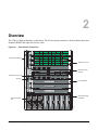
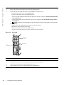
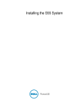
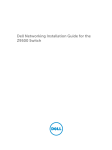
The C300 is a high performance switch/router. The 10-slot system contains two slots for Route Processor
Modules (RPMs) and eight slots for line cards.
Figure 2-1.
C300 Chassis (Front View)
0
1
Front Mount Bracket
2
48-Port Line Card
3
R0
R1
SFM
ACTIVE Alarm
RJ-45
Console
Status Master
RJ-45
Console
Status Master
SFM
ACTIVE Alarm
Compact Flash
Reset
Compact Flash
Reset
Route Processor
Module
4
4-Port Fiber Line Card
Fan Tray
BLNK
5
Line Card Blank
BLNK
6
BLNK
7
BLNK
BLNK
BLNK
BLNK
BLNK
AC Power Supply
Unit Blank
AC Power Supply
Unit
l
O
l
O
l
O
fnC0007mp
Installing and Maintaining the C300 System
11
www.dell.com | support.dell.com
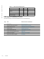
Table 2-1.
C300 Component Requirements
Component
Minimum
Maximum
Field-Replaceable
Backplane (factory installed) 1
1
No
Fan tray
1
1
Yes
RPM
1
2
Yes
Line card
1
8
Yes
AC Power Supply
1
8
Yes
C300 System Installation Process
The Dell Networking recommended installation process is described below.
Step
12
|
Task
Relevant Section in the Manual
1
Prepare the site.
Site Selection Criteria
2
Unpack the chassis and components.
Shipping and Storing Components
3
Install the chassis in a rack.
Installing the Chassis into an Equipment Rack
4
Install the fan tray.
Installing C300 Fan Tray
5
Install the RPMs and line cards.
Installing RPMs and Line Cards
6
Connect console and management cables.
RPM Cables
7
Install the power supplies.
Installing AC Power Supplies
8
Switch on all of the power supplies.
Powering Up
Overview
3
Preparing the Site
Site Selection Criteria
Before beginning the installation process, make sure that the area where you intend to install your C300
meets the following safety requirements:
• It is in a restricted access area.
• It is in a dry, clean, well-ventilated, temperature-controlled room, that is away from heat sources such as
hot air vents or direct sunlight.
• It is away from sources of severe electromagnetic noise.
• Power supply is adequate for power requirements.
•
Connect the C300 System to the appropriate branch circuit protection as defined by local
electrical codes.
WARNING: The C300 does not have a main disconnect device installed. It is the responsibility of the
installer to provide a suitable disconnecting device in the building installation and ensure that it is located/
installed near the equipment and is easily accessible.
• It is positioned in a rack with adequate space in the front, rear, and sides of the unit for proper
ventilation, access to cables, and maintenance access.
•
•
•
Allow at least six inches (16 cm) of clearance around the side intake and exhaust vents.
Allow at least 12 inches (30.5 cm) between two C300s or an C300 and another side airflow
chassis.
Allow at least 18 inches in the front and 20 inches in the rear of the rack.
NOTE: The C-Series does not have an air filter, so take special care in making sure that the installation site
and the chassis itself are cleaned regularly.
Installing and Maintaining the C300 System
13
www.dell.com | support.dell.com
Rack Mounting
When you prepare your equipment rack:
• Make sure that the rack is bolted to the floor and braced to a wall or ceiling.
• Make sure that the rack is permanently grounded to earth ground. The equipment rack must be grounded
to the same ground point used by the service in your area.
• The AC cord is the primary ground.
When you install the chassis, use a level to ensure the chassis is installed level.
Requirements
There are two types of power supplies: Power Supply 1200W-AC and Power Supply 1600W-AC. The
minimum and the redundant power supplies required to operate is listed in the table below. Dell
Networking recommends the redundancy configuration.
Minimum PSUs
Minimum with
Redundant PSUs
Power Supply 1200W-AC/Power Supply 100-120
1600W-AC
2
3
Power Supply 1200W-AC
200-240
2
3
Power Supply 1600W-AC
200-240
1
2
Voltage
The C300 requirements are given below:
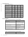
Table 3-1.
14
|
System Specifications
Parameter
Specifications
Nominal Input Voltage
100 - 240 VAC 50/60 Hz
Maximum AC Power Supply Input Current
(Based on 1200 W output for 100/120 V and
1600 W 200/240 V lines)
14 A @ 100 V per AC Power Supply
11 A @ 120 VAC per AC Power Supply
9 A @ 200 VAC per AC Power Supply
7 A @ 240 VAC per AC Power Supply
Maximum System Power Input
9,667 KVA @ 100/120 V
12,596 KVA @ 200/240 V
Maximum Thermal Output at 100/120V
9,235 BTU/hour
Maximum Thermal Output at 200/240V
9,299 BTU/hour
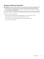
Preparing the Site
Shipping and Storing Components
CAUTION: Do not transport a C300 chassis with the components (line cards, supplies, and RPMs) installed in
the chassis. Place the components in their original protective shipping packaging and original shipping
position. Shipping components installed in the chassis or without their protective packaging, might damage
the components or the chassis backplane.
If you do not install your C300 System and components immediately, Dell Networking recommends you
properly store components (including all extra field-replaceable parts) until you are ready to install them.
Follow these indoor storage guidelines:
• Storage temperature should remain constant ranging from -40°F to 158°F (-40°C to 70°C).
• Non-condensing relative humidity should be maintained with 5 to 95%.
• Store on a dry floor, away from direct sunlight, heat, and air conditioning ducts.
• Store in a dust-free environment.
Preparing the Site
|
15
16
|
Preparing the Site
www.dell.com | support.dell.com
4
Installing C300 Fan Tray
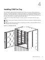
The C300 chassis contains one field-replaceable fan tray. There are two types of fan tray that may be
installed: C300 variable speed fan tray contains six fans that run at varying speeds depending on system
temperature, C300 fixed speed fan tray contains six fans that run at a constant speed. For both types of
trays, air flows through the C300 system toward the fans (right to left) and is exhausted on the fan-side of
the chassis. The fan tray is accessible from the front of the chassis.
Contact Dell Networking Technical Support if you have questions concerning the fan tray for your
system.
NOTE: To ensure proper temperature and airflow control, the fan tray must always be installed and operating
properly.
NOTE: The C300 does not have an air filter so take special care in making sure that the installation site and
the chassis itself are cleaned regularly.
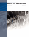
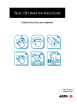
Figure 4-1.
Inserting the Fan Tray
0
1
2
3
R0
R1
4
5
6
7
fnC0003mp
Installing C300 Fan Tray
|
17
www.dell.com | support.dell.com
To install the fan tray:
Step
Task
1
Slide the connector end into the fan slot (see Figure 4-1).
2
Gently push on the front of the tray until it stops. The fan tray should be flush with the chassis.
3
Use a #2 Phillips screwdriver to secure the fan tray into place by tightening the screws at the top and bottom of
the fan tray.
NOTE: The fan tray LED will remain lit when the chassis is ed up and the fan tray is functioning properly.
Removing the Fan Tray
A fan tray failure or a failure of a fan within a fan tray is recognized by a red fan tray LED, a lit RPM
alarm LED, and, if configured, an SNMP trap and alarm event. The failure requires a replacement of the
entire fan tray. While you replace the fan tray, the C300 system operates safely for approximately two (2)
minutes at an ambient temperature of 77° F (25° C).
To remove the fan tray, you must be able to pull the fan tray completely out of the slot (at least 20 inches)
NOTE: The fan tray must always be installed to ensure proper temperature and airflow control.
CAUTION: Fan blades rotate at high speeds and may cause injury if touched. Adhere to the following
instructions to avoid possible injury.
To remove the fan tray:
Step
Task
1
Unscrew the retaining screws at the top and bottom of the fan tray.
2
Use the handle to pull the fan tray out approximately two inches from the back of the chassis (Figure 4-1). Wait
until the fan blades stop rotating (up to 30 seconds), then completely remove the fan tray.
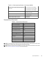
Fan Speed
C300 variable speed fan speed is driven by temperatures measured at the sensor in the fan tray alone. The
sensor is located on the fan tray controller located in the fan tray. Table 4-1 shows the sensor temperature
that determines the fan speed.
Table 4-1.
Fan Speed and Temperature
Degrees Celsius
Fan Speed
Less than 45° C
(Low) 2400 RPM
Between 45 and 55° C
(Med) 3200RPM
Above 55° C
(High) 4000 RPM
C300 fixed speed fan speed is constant and does not change with temperature.
18
|
Installing C300 Fan Tray
5
Installing RPMs and Line Cards
The C300 System accommodates eight line cards and two RPMs.
Route Processor Modules
The C300 system requires the installation of at least one Route Processor Module (RPM); two are
recommended.
• One RPM provides 48 Gigabits of bandwidth to each line card.
• Two RPMs provides 96 Gigabits of bandwidth to each line card.
RPMs are designed to be installed in either the R0 or R1 slot (see Figure 2-1). Do not force RPMs into
line cards slots. RPMs are keyed differently than line cards to prevent improper installation.
NOTE: If your system contains two RPMs, both RPMs must contain the same software image.
RPM Label and LEDs
Table 5-1 describes the RPM LED states and the RPM front panel.
Table 5-1.
RPM Front Panel and LED Descriptions
Section
Label
Description
Management
Console Port
Use this RJ-45 jack for the initial system boot, as well as system configuration and
monitoring. Modem connection is not supported on the Console.
10/100/1000
Ethernet
Use this non-routable Ethernet port to download images and manage the system. FTP and
Telnet operations are supported. This port is an RJ-45.
Port LEDs:
L/A:
Blinking Amber: 100M speed
Solid Amber: 1G speed
Off: 10M speed
Speed:
Blinking Green: Link detected/ Activity
Solid Green: Link detected/ No Activity
Off: No Link/ Card Offline
Alarm LED
Red: Major Alarm—a critical condition exists (such as a severe over temperature condition).
See Alarms for more information.
Flashing red: Minor Alarm—a serious condition exists (such as a single fan failure or a line
card failure). See Alarms for more information.
Unlit: no alarm conditions.
Installing RPMs and Line Cards
|
19
www.dell.com | support.dell.com
Table 5-1.
RPM Front Panel and LED Descriptions (continued)
Section
Label
Description
Flash
Slot
Use the compact flash card (external compact flash memory card) slot to store and retrieve
boot and system images.
In Use LED
Green: flash memory card is in the process of a read or write process. Do not remove the
flash card when the In Use LED is lit.
Unlit: not in use.
Master LED
Indicates that this RPM is the Primary RPM.
Green: primary
Unlit: secondary/ fatal error/ booting
Reset Button
Use this recessed reset switch to reset the RPM by inserting a small object, such as a pen tip,
to depress the button.
SFM Active
Green: Switch Fabric is active
Unlit: Switch Fabric is inactive
Status LED
Green: operational
Red: card problem state
Flashing green: booting/ diagnostics
Unlit: in standby mode or is off
Line Cards
Line cards are hot-swappable. Any line card can be inserted into any line card slot. Line card slots are
labeled 0 to 7; these labels can be seen when the fan tray is installed. Do not force line cards into the RPM
slot.
Line card LEDs are described in the documentation specific to each line card. Refer to the installation
documentation that came with the card for to understand LED appearance and meaning.
Blank Panels
Blanks are required in empty slots to control airflow for adequate system cooling, personal safety, and
EMI containment during operation.
The blank panels do not have board components or connector pins. Align the blank with the guides and
gently slide toward the backplane.
NOTE: All chassis slots must be installed with operational modules or blanks. Always replace cards and blank
panels immediately.
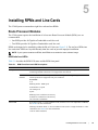
Installing the RPMs and Line Cards
WARNING: Electrostatic discharge (ESD) damage can occur when components are mishandled. Always
wear an ESD-preventive wrist or foot-heel ground strap when handling RPMs or line cards. Place RPMs and
line cards on an antistatic surface when they are not installed.
NOTE: Unlock the levers before inserting the line card into to chassis. Fully engage the locking mechanism
once the card has been inserted; not doing so will cause damage to the card below when that card is inserted.
20
|
Installing RPMs and Line Cards
NOTE: The fan tray face panel has slot number markings for the RPMs and line cards. Insert the fan tray
before the line cards to simplify RPM and line card installation.
Step
1
Task
Extend the left and right card levers by first pressing gently down on the thumb tabs (see Figure 5-1) in the ejector
levers and then pulling the ejector levers simultaneously until they are in the open position. See Figure 5-2.
Figure 5-1.
Depress the thumb tabs
Figure 5-2.
Extend the levers
2
Hold the card assembly by the metal carrier edges. Avoid touching the printed circuit board and connector pins.
3
Align the card with the guide, and gently slide it into any line card slot until the card is about halfway into the slot.
NOTE: Use the markings on the fan tray to determine which slots are for the RPMs and which are for the line
cards.
4
Continue sliding the line card until you feel the connectors engage with the chassis backplane.
Installing RPMs and Line Cards
|
21
www.dell.com | support.dell.com
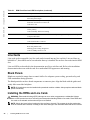
Step
5
Task
Rotate the levers towards the card to seat the backplane connectors and line card in place. Push on the knurled
section of the levers until the thumb tabs pop up and lock the unit in place. See Figure 5-3 and Figure 5-4.
Figure 5-3.
Close the levers
Figure 5-4.
Press the knurled section of the lever
NOTE: Installing a card without fully engaging the locking mechanism will damage the EMI seal on the card
below it when that card is inserted.
6
Install a blank panel in all slots that do not have a card and secure it with the screws provided.
NOTE: The blank panels for RPMs and line cards are different sizes (RPM blanks are smaller); be sure that
blank panels are installed in the correct slots.
22
|
Installing RPMs and Line Cards
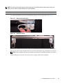
Figure 5-5.
Installing a Line Card
Card Guide
Card Lever
fnC0005mp
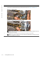
Figure 5-6.
Installing an RPM
Card Lever
Card Guide
fnC0006mp
Installing RPMs and Line Cards
|
23
www.dell.com | support.dell.com
24
|
Installing RPMs and Line Cards
6
RPM Cables
Connecting the Console Port
The console port is an asynchronous serial port. If you connect a device to these ports, it must be capable
of asynchronous transmission. Your terminal or terminal emulation mode must be set to VT100 with the
following settings:
• 9600 baud rate (To avoid autobaud input, the default is set to a 9600 bps.)
• No parity
• 8 data bits
• 1 stop bit
• Window Terminal Emulator option set to NO
• 24 lines X 80 characters
• No flow control
Cable and Adapter Pin Assignments
Use the C300 System Console port on the RPM to connect to a terminal port, PC serial port, or a terminal
server to configure and monitor your system. An RJ-45 Ethernet cable is required to connect to the
Ethernet port.
The Console port is an RJ-45, the pinouts of which are shown in Figure 6-1.
Figure 6-1.
Pinouts for an RJ-45 Connector End of Adaptors
fnC0011mp
87654321
Table 6-1 displays the RJ-45 console port pin assignments.
Installing and Maintaining the C300 System
25
www.dell.com | support.dell.com
Table 6-1.
Console Port (RJ-45) Pin Assignments
Pin
Signal
Input/Output
1
NC (unused)
-
2
DTR
Output
3
TxD
Output
4
GND
-
5
GND
-
6
RxD
Input
7
DSR
Input
8
NC (unused)
-
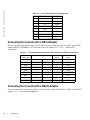
Accessing the Console with a DB-9 Adapter
You can connect to the console using a RJ-45 to RJ-45 rollover cable and a RJ-45 to DB-9 female DTE
adapter (labeled “TERMINAL”) to a terminal server (for example, PC). Table 6-2 lists the pin
assignments.
Table 6-2.
Pin Assignments Between the C300 Console and a DTE Terminal Server
C300 System
Console Port
RJ-45 to RJ-45 Rollover Cable
RJ-45 to DB-9
Adapter
Terminal Server
Device
Signal
RJ-45 pinout
RJ-45 Pinout
DB-9 Pin
Signal
RTS
1
8
8
CTS
DTR
2
7
6
DSR
TxD
3
6
2
RxD
GND
4
5
5
GND
GND
5
4
5
GND
RxD
6
3
3
TxD
DSR
7
2
4
DTR
CTS
8
1
7
RTS
Accessing the Console with a DB-25 Adapter
You can connect to the console using a RJ-45 to RJ-45 rollover cable and a RJ-45 to a DB-25 female DTE
adapter. Table 6-3 lists the pin assignments.
26
|
RPM Cables
Table 6-3.
Pin Assignments Between C300 Console and DB-25 Adapter
C300 System
Console Port
RJ-45 to RJ-45 Rollover Cable
RJ-45 to DB-25
Modem Adapter
Terminal Server
Device
Signal
RJ-45 Pinout
RJ-45 Pinout
DB-25 Pinout
Signal
RTS
1
8
5
CTS
DTR
2
7
6
DSR
TxD
3
6
3
RxD
GND
4
5
7
GND
GND
5
4
7
GND
RxD
6
3
2
TxD
DSR
7
2
20
DTR
CTS
8
1
RTS
RPM Cables
|
27
28
|
RPM Cables
www.dell.com | support.dell.com
7
Installing AC Power Supplies
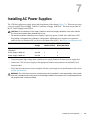
The C300 has eight power supply slots at the front-bottom of the chassis (Figure 7-1). There are two types
of power supplies: Power Supply 1200W-AC and Power Supply 1600W-AC. The slots accept either of
the AC Power Supply Units (PSUs).
CAUTION: Do not install the Power Supply 1200W-AC and Power Supply 1600W-AC in the same chassis.
The line cards will power down and data may be lost.
• The minimum and the redundant power supplies required to operate is listed in the table below. Dell
Networking recommends the redundancy configuration. Additional power supplies are required to
enable Power over Ethernet (PoE) or Power over Ethernet Plus (PoE+). See Power Over Ethernet (PoE).
Minimum PSUs
Minimum with
Redundant PSUs
Power Supply 1200W-AC/Power Supply 100-120
1600W-AC
2
3
Power Supply 1200W-AC
200-240
2
3
Power Supply 1600W-AC
200-240
1
2
Voltage
• To protect against high-voltage shock, install a power supply blank on all unused power supply slots.
• Connect the C300 AC power supply to the appropriate branch circuit protection as defined by local
electrical codes.
• Verify that the remote power source complies with the system input power specifications in the section
System Specifications
WARNING: The C300 does not have a main disconnect device installed. It is the responsibility of the installer
to provide a suitable disconnecting device in the building installation and ensure that it is located/installed near
the equipment and is easily accessible.
Installing AC Power Supplies
|
29
www.dell.com | support.dell.com
Figure 7-1.
Power Supply Location
fnC0001mp
30
|
Installing AC Power Supplies
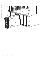
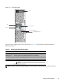
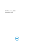
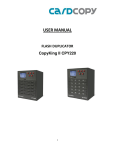
Figure 7-2.
AC Power Supply
Handle
l
O
Switch
AC Power Receptacle
Power LED
Retaining Pin Threaded Hole
Power Supply Retaining Pin
fnC0002mp
Each AC power supply has one LED as described in Table 7-1. This LED does not function unless an
RPM is installed.
Table 7-1.
Power Supply Unit LED Description
Status
Description
Off
The unit is off.
Flashing Green
Warning: the unit is beyond temperature and/or current limits.
Solid Green
The unit is functioning properly
Flashing Red
The unit has failed, possibly due to temperature or current beyond its limits.
Solid Red
The unit is switched on but either unplugged or has low input voltage.
NOTE: For a unit LED to light red, there must be at least one other
unit operating in the chassis.
NOTE: If there is a failure in the power supply, it must be replaced. Power supplies are not field serviceable.
Installing AC Power Supplies
|
31
www.dell.com | support.dell.com
Installing the AC Power Supply
WARNING: Use only the power cord supplied with the power supply. Do not supply power to your C300
system until the power supplies, blank panels, fan tray, RPMs, and line cards have been installed.
WARNING: The C300 operates in either of two voltage ranges. Each range supports a different power supply
configuration. As a safety precaution, do not install more than the recommended maximum number of PSUs
(given by the table below), as this causes high leakage current. Install blank panels in all unused PSU slots.
Voltage
Frequency
Maximum PSU
100 -120
50/60Hz
7 primary + 1 redundant
200 - 240
50/60Hz
7 primary + 1 redundant
WARNING:
NOTE: For system input power requirements see System Specifications.
You can install any AC power supply into any power supply slot. Dell Networking recommends installing
power supplies starting from the left side of the chassis, leaving no blank slots between units.
To install an AC power supply:
Step
Task
1
Verify the switch is in the OFF (bottom) position.
2
Slide the power supply into the left most power supply slot. See Figure 7-1 for correct orientation.
3
Plug the power cord into the power receptacle in the face of the power supply. See Figure 7-2 for location.
4
Plug the power cord into an AC power outlet.
5
Repeat steps 1 through 4 for the remaining power supplies.
Power Cord Requirements
If using a power cord other then a Dell Networking supplied power cord, the power source end of the
power cord must have an appropriately sized plug that complies with your local electrical codes.
Conductor size must also conform to your local electrical codes.
CAUTION: The power cord is the main power disconnect device; ensure that the socket-outlet is located/
installed near the equipment and is easily accessible.
Power Over Ethernet (PoE)
The C-Series can transmit power to Ethernet devices over the signal pairs of an Unshielded Twisted Pair
(UTP) cable. A maximum of 15.4 Watts (at 48 Volts) can be transmitted over a link.
The chassis transmits power to connected IEEE 802.3af-compliant devices via ports that are enabled with
PoE. A minimum of four AC power supplies are required to enable PoE, and 96 ports can be enabled per
PSU, starting at the fourth, as described in Table 7-2.
32
|
Installing AC Power Supplies
Table 7-2.
PoE Ports per Power Supply 1200W-AC
Power Supply Units
Max PoE Ports
1
—
2
—
3
System Redundancy
4
96
5
192
6
288
7
384
8
PoE Redundancy
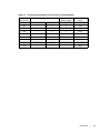
Power Over Ethernet Plus (PoE+)
The C-Series can transmit power to Ethernet devices over the signal pairs of an Unshielded Twisted Pair
(UTP) cable. A maximum of 30.0 Watts (at 53 Volts) can be transmitted over a link. The chassis transmits
power to connected IEEE 802.3at-compliant devices via ports that are enabled with PoE+. A minimum of
three Power Supply 1600W-AC power supplies are required to enable PoE+. The higher power of PoE+
(30W/port) is available only with Power Supply 1600W-AC and the PoE+ line card.
Table 7-3.
Maximum PoE+ Ports Support
Power Supply Units
Max PoE+ Ports
Power Supply 1600W-AC Power Supply 1600W-AC
at highline
at lowline
1
—
—
2
System Redundancy
—
3
53
System Redundancy
4
106
49
5
160
98
6
213
147
7
266
197
8
320
237
Installing AC Power Supplies
|
33
www.dell.com | support.dell.com
34
|
Installing AC Power Supplies
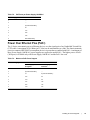
8
Installing DC Power Entry Modules
The C300 has eight supply slots at the front-bottom of the chassis (Figure 8-2). The slots accept either AC
Power Supplies (PSUs) or DC Power Entry Modules (PEMs). Dell Networking does not support the use
of a combination of AC and DC.
• If you select DC, the C300 requires at least one DC PEM for operation, but Dell Networking
recommends a one-plus-one redundancy configuration. Those DC PEMs are inserted in slots 0 and 7.
• To protect against high-voltage shock, install a supply blank on all unused supply slots.
NOTE: The C300 DC Power Entry Module does not support PoE or PoE+ line cards.
NOTE: Some CH-C300 chassis may require Dell Networking assistance when using some DC power
supplies. Please contact the Dell Networking TAC if you experience any difficulty during installation.
Recommended Normal Operating Conditions
Table 8-1.
Table 8-2.
Input voltage
Input Ranges
Maximum
-44V (minimum)
1408 watts
-48V (typical)
1536 watts
-55V (maximum)
1760 watts
Operating Ranges
Ambient Temperature
Operating Range
-5° C to +40° C
Storage Range
-40° C to +70 ° C
Humidity
Operating Range
5-85% RH
Storage Range
5-90% RH
Redundancy
For full facility redundancy, install two DC PEMs. Each PEM must be attached to an independent source
with a dedicated circuit breaker sized in accordance with your local building and electrical safety codes.
Cable and Connector Requirements
You must provide your own cables to connect to a remote source (a circuit breaker panel, for example) in
your equipment rack or facility. Cables must be sized to meet the following criteria:
Installing DC Power Entry Modules
|
35
www.dell.com | support.dell.com
• Rated for 60A service to allow for a fully loaded C300 system per NEC in the United States or
internationally, per local safety codes.
• Limit voltage drop across the cable length to 0.5V or less.
Apply a coat of anti-oxidant paste to unplated metal contact surfaces before you make the cable
connections. File unplated connectors, braided straps, and bus bars to a shiny finish. It is not necessary to
file and coat tinned, solder plated, or silver-plated connectors or other plated connection surfaces, such as
those on the PEM studs.
NOTE: Take precautions against over-tightening the screws or nuts on this device.
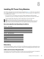
Installing a DC PEM
Step
Task
1
Turn the remote power source (the circuit breaker panel) to the OFF position.
2
Turn the over-current switch (located on the PEM front panel) to the OFF position.
3
Loosen the PEM safety cover retaining screw and remove the cover (Figure 8-1).
Figure 8-1.
DC PEM Faceplate
PEM Safety Cover
Grounding
Stud
Retaining Latch
Over-Current
Switch
Status LED
fn003lp
Handle
36
|
Installing DC Power Entry Modules
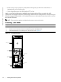
Step
4
Task (continued)
Slide the PEM into slot 0 or 7 (see (Figure 8-2). If you are installing redundant PEMs, install in both slots 0 and 7.
NOTE: Fill all empty slots with blank panels.
Insert 2 DC PEMs in Slots 0 and 7
fn
00
02
lp
Figure 8-2.
5
Secure the PEM in place by tightening the retaining latch on each module so that the arrow points down
(Figure 8-2).
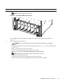
6
Secure the chassis ground connection:
WARNING: You must complete the ground connection before proceeding with any other PEM
connection.
Locate the chassis ground connector stud on the PEM front panel (see Figure 8-3). It is the single stud below
the safety cover.
b Remove the nut and washer from the ground stud.
c Apply a coat of anti-oxidant paste to the connector stud, if required.
d Install the grounding cable. This cable is typically green or green and yellow.
a
NOTE: Termination points require UL-listed 1-hole lug with a 1/4-inch hole.
e Replace the washer and nut on the stud.
f Secure the nut with a nut driver or torque wrench (not to exceed 4 ft/lbs).
g Connect the opposite end of the grounding cable to the appropriate nearest grounding.
Installing DC Power Entry Modules
|
37
www.dell.com | support.dell.com
Step
Task (continued)
7
Remove the outer nuts and washers from each of the remaining studs.
8
Connect the -48 VDC and Return cables from each PEM to the remote sources.
a Verify that the remote source is in the OFF position.
b Locate the appropriate studs on the PEM front panel.
• The two top studs (furthest from the GND) are the return (+48V DC) connection. The cable attached to these
studs is typically red.
• The two bottom studs (closest to GND) are the -48 V DC connection. The cable attached to these studs is
typically black.
NOTE: Cables must be terminated only with a UL-listed 2-hole lug to accommodate 1/4-inch studs with
3/4-inch spacing.
Apply a coat of anti-oxidant paste to the connector studs, if required.
Replace the washers and nuts on the studs.
e Route the terminated cables out toward the rack rail.
f Secure the nuts with a nut driver or torque wrench (not to exceed 4 ft/lbs).
c
d
Figure 8-3.
Grounding
Return (+48V)
Connectors
-48V Connectors
Ground
Connector
Step
9
38
|
Task (continued)
Replace the safety cover and tighten the captive screw.
Note that the safety cover can be rotated to accommodate system configurations.
10
Turn the Over-Current Protector to the ON position (Figure 8-1).
11
Turn the remote source (the circuit breaker panel) to the ON position.
Installing DC Power Entry Modules
Status LED
The status LED indicates the condition of the PEM.
Table 8-3.
Status LED Descriptions
LED Display
Meaning
Description
Off
Off
No input voltage is present, or the circuit is turned
off.
Flashing Green
Over-Current Warning
The load current is above the warning level
threshold. This warning takes precedence over the
temperature warning.
Flashing Green
Over-Temperature Warning
The temperature is above the temperature warning
threshold.
Solid Green
On
The PEM is running normally.
Removing a DC PEM
The left chassis PEM slot is labelled “0” and the right chassis PEM slot is labelled “1.” For full
redundancy, each PEM must be attached to a dedicated circuit breaker. For example, PEM “0” connects
to circuit breaker “0” and PEM “1” connects to circuit breaker “1.”
WARNING: Prevent exposure and contact with hazardous voltages. Do not attempt to operate this system
with the safety cover removed.
Step
Task
1
Switch the Over Current Protector (located on the PEM front panel) to the OFF position.
2
Turn off the PEM. Ensure that the remote source is in the OFF position and that the PEM Status LED and Pwr In
OK LED are off.
3
Loosen the retaining screw and remove PEM safety cover (see Figure 8-1).
4
Disconnect cables attached to the PEM.
5
Slide the PEM out of the slot.
6
If you are not replacing the PEM, close the empty slot with a blank panels.
Installing DC Power Entry Modules
|
39
www.dell.com | support.dell.com
40
|
Installing DC Power Entry Modules
9
Powering Up
Before you supply power to the chassis, Dell Networking recommends that you re-inspect your
equipment rack and chassis. Verify that:
• The equipment rack or properly secured and grounded.
• The chassis is bolted and secured into your equipment rack.
• Make sure the ambient temperature around the unit (which may be higher than the room temperature) is
within the limit specified for the unit.
• Make sure there is sufficient airflow around the unit.
• Make sure electrical circuits are not overloaded – consider the nameplate rating of all the connected
equipment, and make sure you have over current protection.
• At least one supply module at highline or two supply modules at lowline are installed.
• All supply module is properly installed.
• All supply modules are switched to the OFF (bottom) position.
• The remote source complies with the input specifications in the section System Specifications.
•
Cables connect to the remote source.
• The fan tray is installed and cannot be removed by pulling on the fan tray handle.
• At least one RPM is installed.
• All line cards and RPMs are properly installed and secured.
• All chassis slots are filled. Blank panels and covers are installed in all empty slots.
• Make sure no objects are placed on top of the unit.
• Make sure the equipment is properly grounded.
Installing and Maintaining the C300 System
41
www.dell.com | support.dell.com
Supplying
WARNING: Never operate the C300 System without a fan tray.
WARNING: The C300 operates in either of two voltage ranges. Each range supports a different supply
configuration. As a safety precaution, do not install more than the recommended maximum number of PSUs
(given by the table below), as this causes high leakage current. Install blank panels in all unused PSU slots.
Voltage
Frequency
Maximum PSU
100 -120
50/60Hz
7 primary + 1 redundant
200 - 240
50/60Hz
7 primary + 1 redundant
To supply the C300 system:
Step
Task
1
Verify that the source complies with the system input requirements in the section System Specifications.
2
Energize the remote source or outlet.
3
Toggle the switch on the AC supplies to the ON (top) position.
4
In an AC Supply, the LEDs should be green.
If these LEDs are not lit green:
Check that the unit is properly installed.
Verify the source.
If the supply cannot be verified, off all modules and replace the unit.
5
The fan tray LED should be green (online). You should be able to hear the air flowing through the chassis.
If the fans are not operating properly or air is not flowing through the chassis:
off all supplies.
Verify that the fan tray is properly installed.
If the fan tray LED remains unlit, down the unit, and replace the fan tray.
To turn off the AC supplies:
• Toggle the switch two the OFF position.
• Unplug the cord from the receptacle on the front of the supply.
• Verify that the LEDs are unlit.
After you supply to the system, the following should occur:
• The fan tray should be operating.
• The green (online) fan tray, RPM, and line card LEDs should be lit and remain lit as long as the system
is receiving and is operational.
When you supply to the C300, the system performs a series of -on self tests. RPM and line card LEDs
blink as the diagnostic programs run. No user interaction is required at this point. Observe the process on
your console monitor. When the boot process is complete, the card LEDs remain online (green) and the
console monitor displays the Command Line Interface (CLI) prompt.
42
|
Powering Up
NOTE: Do not press any keys or control sequences at any time during the boot process. Doing so may cause
the boot process to terminate.
Booting from the BOOT_USER Prompt
The initial boot operation automatically brings up the system to the runtime CLI. To interrupt the
automatic boot process, issue a break key sequence (CNTL ^ or CNTL~ ). The console monitor will
display the default BOOT_USER # prompt. Refer to “Alarms” on page 61 for instructions to continue the
boot process.
Powering Up
|
43
44
|
Powering Up
www.dell.com | support.dell.com
10
Removing and Replacing Components
This section provides instructions for removing and replacing the following C300 components:
• Removing and Replacing the Fan Tray
• Removing and Replacing Power Supply Units
• Removing and Replacing a Line Card
When a component fails, the C300 System system triggers an alarm LED (located on the active RPM),
disables or changes component Status LEDs, and sends events to the SNMP trap and show alarms table
(if this feature is configured). Refer to Appendix , for more information on alarms.
WARNING: Electrostatic discharge (ESD) damage can occur when components are mishandled. Always
wear an ESD-preventive wrist or ankle strap when handling RPMs and line cards. Connect the ESD strap to
the grounding plug located on the front of the chassis. Place RPMs and line cards on an antistatic surface and
anti-static bags when they are not installed.
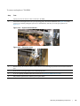
Removing and Replacing the Fan Tray
A fan tray failure or a failure of a fan within a fan tray is recognized by a red fan tray LED, a lit RPM
alarm LED, and, if configured, an SNMP trap and alarm event. The failure requires a replacement of the
entire fan tray. While you replace the fan tray, the C300 system will operate safely for approximately two
(2) minutes at an ambient temperature of 77° F (25° C).
To remove and replace the fan tray, you must be able to pull the fan tray completely out of the slot (at
least 20 inches).
WARNING: Fan blades rotate at high speeds and may cause injury if touched. Adhere to the following
instructions to avoid possible injury.
WARNING: To ensure proper temperature and airflow control, the fan tray must always be installed.
Installing and Maintaining the C300 System
45
www.dell.com | support.dell.com
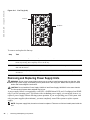
Figure 10-1.
Fan Tray (Left)
Connector
Fan Blades
fnC0004mp
To remove and replace the fan tray:
Step
Task
1
Unscrew the retaining screws at the top and bottom of the fan tray.
2
Use the handle to pull the fan tray out approximately two inches from the chassis. Wait 30 seconds, until the fan
blades stop rotating, then completely remove the fan tray.
3
Insert the new fan tray into the chassis. Guide the tray firmly into the slot until it stops and the handle end is
flush with the chassis.
4
Secure the fan tray into place by tightening the screws at the top and bottom of the fan tray using a #2 Phillips
screwdriver.
Removing and Replacing Power Supply Units
WARNING: Do not remove a panel blank unless you are ready to install a power supply into that slot. After
removing a power supply, immediately place a panel blank in the empty slot. Blanks are required to control
airflow and electromagnetic interference.
CAUTION: Do not install the Power Supply 1200W-AC and Power Supply 1600W-AC in the same chassis.
The line cards will power down and data may be lost.
A power supply failure is recognized by a red LED, a lit RPM alarm LED, and, if configured, an SNMP
trap. If you are operating your C300 chassis with a redundant power supply, you can install, remove, or
replace a power supply without affecting system operation. If you are operating your C300 system with
only two power supplies (the minimum), you must completely turn off the system to replace a power
supply.
NOTE: If a power supply fails, the entire unit must be replaced. There are no field serviceable parts inside the
unit.
46
|
Removing and Replacing Components
To remove and replace a supply:
Step
Task
1
If the chassis is in the non-redundant power supply configuration, shut down the chassis.
If you are removing a redundant power supply, toggle the switch on the power supply to the OFF (bottom)
position.
2
If applicable, disconnect the power cable from the AC power source and the front of the power supply.
3
Pull the power supply out of the slot using the handle.
4
If you are not replacing the power supply, insert a panel blank. See Figure 2-1 for the correct orientation.
5
Toggle the switch on the replacement power supply to the OFF position.
6
Slide the new power supply into the power supply slot. See Figure 7-1 for the correct orientation.
7
Plug the AC power cord into the power receptacle in the face of the power supply. See Figure 7-2 for the location.
8
Plug the AC power cord into an AC outlet.
9
Toggle the switch on the power supply to the ON (top) position.
Turn up the chassis if necessary.
10
Removing and Replacing a Line Card
WARNING: Do not remove a panel blank unless you are ready to install a line card into that slot. After
removing a line card, immediately place a panel blank in the empty slot. Blanks are required to control airflow
and electromagnetic interference.
You can add, replace, or remove C300 line cards without interrupting the system power or system
operations.
To remove and replace C300 line cards:
Step
Task
1
Unplug the network interface cables connected to the line card.
Removing and Replacing Components
|
47
www.dell.com | support.dell.com
Step
Task (continued)
2
Extend the left and right card levers by first pressing gently down on the thumb tabs (see Figure 10-2) in the
ejector levers and then pulling the ejector levers simultaneously until they are in the open position. See
Figure 10-3.
Figure 10-2.
Depress the thumb tabs
Figure 10-3.
Extend the levers
3
Pull the card by the card levers until it is out of the slot. Avoid touching the printed circuit board and connector
pins.
4
If you are not replacing the card immediately, install a blank panel.
5
If you are replacing the card, follow the instructions in Installing the RPMs and Line Cards.
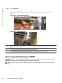
Removing and Replacing an RPM
WARNING: After removing an RPM, place a panel blank in the empty slot before powering up the chassis.
Blanks are required to control airflow and electromagnetic interference.
NOTE: The C300 requires at least one RPM to operate. The chassis powers down if you remove the only
RPM.
48
|
Removing and Replacing Components
To remove and replace a C300 RPM:
Step
Task
1
Unplug any network interface cables connected to the RPM.
2
Extend the left and right card levers by first pressing gently down on the thumb tabs (see Figure 10-4) in the
ejector levers and then pulling the ejector levers simultaneously until they are in the open position. See
Figure 10-5.
Figure 10-4.
Depress the thumb tabs
Figure 10-5.
Extend the levers
3
Pull the card by the card levers until it is out of the slot. Avoid touching the printed circuit board and connector
pins.
4
If you are not replacing the RPM, insert an RPM blank panel.
5
If you are replacing the RPM, follow the instructions in Installing the RPMs and Line Cards.
6
Only after the replacement is installed, power up the chassis.
Removing and Replacing Components
|
49
www.dell.com | support.dell.com
50
|
Removing and Replacing Components
11
Installing the Chassis
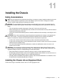
Safety Considerations
NOTE: Use an equipment lift or pallet jack when lifting or moving the chassis. Install the chassis into the rack
before inserting chassis components. Lift the C300 chassis only from the bottom. Lifting by the chassis
shelves or power supply openings will damage the chassis.
WARNING: To prevent bodily injury when mounting or servicing this unit in a rack, you must take special
precautions to ensure that the system remains stable. The following guidelines are provided to ensure your
safety:
•
•
•
This unit should be mounted at the bottom of the rack if it is the only unit in the rack.
When mounting this unit in a partially filled rack, load the rack from the bottom to the top with the heaviest
component at the bottom of the rack.
If the rack is provided with stabilizing devices, install the stabilizers before mounting or servicing the unit in
the rack.
ATTENTION: Pour éviter toute blessure corporelle pendant les opérations de montage ou de réparation de
cette unité en casier, il convient de prendre des précautions spéciales afin de maintenir la stabilité du
système. Les directives ci-dessous sont destinées à assurer la protection du personnel:
•
•
•
Si cette unité constitue la seule unité montée en casier, elle doit être placée dans le bas.
Si cette unité est montée dans un casier partiellement rempli, charger le casier de bas en haut en plaçant
l'élément le plus lourd dans le bas.
Si le casier est équipé de dispositifs stabilisateurs, installer les stabilisateurs avant de monter ou de
réparer l'unité en casier.
WARNUNG: Zur Vermeidung von Körperverletzung beim Anbringen oder Warten dieser Einheit in einem
Gestell müssen Sie besondere Vorkehrungen treffen, um sicherzustellen, daß das System stabil bleibt. Die
folgenden Richtlinien sollen zur Gewährleistung Ihrer Sicherheit dienen:
•
•
•
Wenn diese Einheit die einzige im Gestell ist, sollte sie unten im Gestell angebracht werden.
Bei Anbringung dieser Einheit in einem zum Teil gefüllten Gestell ist das Gestell von unten nach oben zu
laden, wobei das schwerste Bauteil unten im Gestell anzubringen ist.
Wird das Gestell mit Stabilisierungszubehör geliefert, sind zuerst die Stabilisatoren zu installieren, bevor
Sie die Einheit im Gestell anbringen oder sie warten.
Installing the Chassis into an Equipment Rack
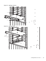
Follow these steps to install the chassis into a 19-inch equipment rack:
Installing the Chassis
|
51
www.dell.com | support.dell.com
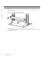
Step
1
Task
Install the equipment rack bar. This bar enables you to easily position the chassis into the rack and stabilizes the
chassis.
• Orient the equipment rack bar at the desired location in the rack, with the arrows pointing up and the smooth
side facing outward.
Figure 11-1.
Installing the Equipment Rack Bar
fnC0008mp
52
|
2
Attach the bar to the rack (see Figure 11-1) using the mounting screws provided with your rack.
3
Use an equipment lift to align the chassis rack-mount holes with the equipment rack holes, and situate the chassis
on top of the equipment rack bar.
Installing the Chassis
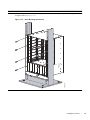
Step
4
Task
Insert screws (provided with your rack) through the chassis rack-mounting bracket and into the equipment rack,
and tighten them (see Figure 11-2).
Figure 11-2.
Rack Mounting the Chassis
fnC0009mp
Installing the Chassis
|
53
54
|
Installing the Chassis
www.dell.com | support.dell.com
12
System Boot
When you supply power to the C300 system, the system performs a series of on self-tests. RPM and line
card Status LEDs blink during initialization No user interaction is required as long as the boot process
proceeds without interruption. Observe the process on your console monitor. When the boot process is
complete, the RPM and line card Status LEDs remain online (green) and the console monitor displays the
command line interface (CLI) prompt, FTOS>.
The RPM cards in the C300 system use a Compact Flash card (external flash memory card) to store and
retrieve boot and system images. This is the default storage area for the boot files and the startup
configuration file. Upon system boot up or a system reset, the boot process uses parameters stored in nonvolatile random access memory (NVRAM) to boot the system.
Each RPM card is equipped with a slot for an external flash memory card (slot0). You can copy the image
files and configuration files to the external flash device on the primary RPM. You can also begin your
boot process by accessing a remote server containing the boot image and system image files.
NOTE: The C300 system supports up to a 40-character file name length, up to a 180-character local file path
length, and up to a 256-character remote file path length.
For information about the Compact Flash card, refer to Chapter 13, The Compact Flash Card.
Booting from the BOOT_USER Prompt
To get into the BOOT_USER mode, issue a break control sequence (CNTL+^) to interrupt the automatic
boot process or you may enter the mode if you experience boot problems. This mode allows you to
modify the parameters necessary to manage the boot process. Only console port access is enabled for the
BOOT_USER mode.
The BOOT_USER # prompt appears after an autoboot interruption. This is the default boot prompt, not
the CLI prompt.
In some display outputs, you can continue the help screen display by pressing ENTER or can stop the
output by entering q and then ENTER. You can abbreviate the boot commands by entering only the first
letter of a command word. (In the BOOT_USER mode, you cannot press the TAB key to complete
commands.) A matching algorithm displays the command starting with the letter or letters you entered.
For example, b displays the commands starting with the letter b, boot change and boot selector. Entering
s h displays the syntax help information. All commands are case insensitive.
System Boot
|
55
www.dell.com | support.dell.com
To configure the chassis from the BOOT_USER prompt, use the following commands:
Command
help
or
?
boot change {primary | secondary |
default}
Purpose
• Enter help or ? to display a list of available commands and syntax.
• Enter syntax help t display syntax information and variable descriptions.
If your configuration displays no pre-configured operating system boot
parameters, use the boot change command to edit appropriate fields.
• The primary operating system boot parameters are used in the first attempt
to boot the system.
• The secondary operating system boot parameters are used if the primary
operating system boot selection is not available.
• The default operating system boot parameters are used if the secondary
operating system boot parameter is not available. The default parameters
always reside on the internal flash drive (flash).
NOTE: These parameters, as well as other boot parameters, can be
modified in run-time mode
When you enter the boot change command, you are prompted for a response.
• Enter a new parameter or press the ENTER key (carriage return) to accept
the default parameter.
• Enter . (period) to clear a field.
• Enter - (dash) to edit a field above the current cursor position.
NOTE: When you enter a new parameter that extends beyond 80
characters, you cannot use the BACKSPACE key to correct any mistakes. If
you make a mistake, you must re-enter the parameter.
show bootvar
This command displays the current operating system boot configuration
parameters
show bootflash
This command displays information about the current boot ROM.
interface management port config
100m
interface management port config
10m
interface management port config
auto-negotiate
interface management port config
no auto-negotiate
interface management port config
full-duplex
interface management port config
half-duplex
interface management port config
show
56
|
System Boot
• Use these commands to set the speed and duplex settings for the
Management interface. The default setting is full-duplex and autonegotiation.
• Use the interface management port config show command to view
the management interface’s physical settings.
Command
show interface management
ethernet
interface management ethernet ip
address ip-address ip-address-mask
Purpose (continued)
• Use the show interface management ethernet command to display
the IP address and network mask of the Management Ethernet port.
• If the show command output does not display configured IP address
information, use the interface management ethernet ip address ipaddress ip-address-mask command to set the IP address of the
Management Ethernet port for network (ftp/tftp) operating system boot.
Use CIDR block notation for the subnet mask,
boot zero {primary | secondary |
default}
Delete the boot configuration.
reload
Reload the software.
The autoboot program initializes and displays self-test results on the console
screen.
NOTE: Do not press the break control sequence at any time during
the boot/reboot process. Doing so causes the boot process to terminate.
Refer to the C-Series FTOS Command Line Reference for BOOT_USER mode commands and
commands for run-time modes.
System Boot
|
57
58
|
System Boot
www.dell.com | support.dell.com
13
The Compact Flash Card
Each RPM is designed with a slot (slot0:) to accommodate a Compact Flash Card (external compact flash
memory card). You can use the Compact Flash Card to store and retrieve boot and system images. For
complex configurations, you can copy your configurations onto the Compact Flash Card and then transfer
the configuration to other C300 systems in your network.
NOTE: Use only a Dell Networking Compact memory card in your C300 System. Additional memory cards
can be purchased from Dell Networking.
Inserting the Compact Flash Card
NOTE: Insert the Compact Flash Card either before system boot or after the system has completed booting
and is in run-time mode.
To install the Compact Flash card:
Step
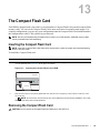
1
Task
Hold the flash card horizontally with the side with the serial number facing up (the numbers should be oriented so
you can read them) See Figure 13-1 for the proper orientation.
Figure 13-1.
Inserting the Compact Flash Card in RPM
fnC0010mp
Compact Flash
S/N 012345678
2
Insert the flash card into the primary RPM flash slot until the card is completely seated with the connectors at the
rear of the slot.
NOTE: Do not force the card into the slot. The slot is designed to prevent improper installation. The In Use
LED lights only during read or write operations.
Removing the Compact Flash Card
CAUTION: Do not remove the Compact Flash Card when the In Use LED is lit.
The Compact Flash Card
|
59
www.dell.com | support.dell.com
To remove the flash memory card:
Step
Task
1
Make sure that the In Use LED is not lit, and gently depress the flash card in the slot. The card should partially
eject out of the slot.
2
Remove the card, and place it in an antistatic bag.
Formatting the Compact Flash Card
New Compact Flash cards must be formatted in the C300 before use.
Flash cards used on systems other than the C300 as well as cards formatted on PCs must be reformatted
in the C300 flash slot before they can be used. Formatting erases all information stored on the flash card.
To format the Compact Flash card:
Step
Task
1
Insert the flash card into the flash slot on the primary RPM.
2
In the CLI, enter format slot0:
FTOS supports up to a 40-character file name length, up to a 180-character local file path length, and up
to a 256-character remote file path length.
60
|
The Compact Flash Card
A
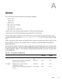
Alarms
The C300 System generates alarms for the following conditions:
• fan tray status
•
supply status
• RPMs status
• high temperature on RPMs
• line cards status
• high temperature on line cards
A major alarm is any fault that would render the C300 System non-functional.
A minor alarm is any fault that threatens the operation of the C300 System.
You can monitor alarm conditions on the C300 System system through the console and LEDs. If you
configure the SNMP command (snmp-server enable traps envmon), the FTOS also sends an SNMP
trap.
In the C300 System system, alarms are logged for each occurrence, but the system may not send an event
log for multiple occurrences. For example, whenever a module exceeds the shutdown threshold, the
module shuts down.
If more than one module exceeds the warning or high temperature thresholds within a five minute period,
the system generates one event for all effected modules but alarms are logged for each occurrence. If the
modules temperature falls to 5° lower than the warning threshold temperature, the system clears the alarm
and an SNMP trap.
Table A-1.
Alarm Events and Reporting
Module
Alarm Event
Alarm LED
Reported in
event log
Status LED on
Module
Fan tray
One fan within the module fails
minor (blinking
red)
minor
N/A
More than one fan within the module fails or
hardware failure in the module
major (red)
major
unlit
Hardware failure in a non-redundant
configuration (2 supplies)
major (red)
major
unlit
minor
unlit
AC Supplies
Hardware failure in a redundant configuration (3 minor (amber)
or more)
Alarms
|
61
www.dell.com | support.dell.com
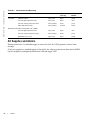
Table A-1.
Alarm Events and Reporting
Module
Alarm Event
Alarm LED
Reported in
event log
Status LED on
Module
Line Card
Hardware failure
major (red)
major
amber
Exceeds high temperature limit
major (red)
major
unlit
Exceeds warning temperature limit
minor (amber)
minor
green
Individual interface fails
minor (amber)
reported
amber
Exceeds high temperature limit
major (red)
major
unlit
Exceeds warning temperature limit
minor (amber)
minor
green
RPM fails but CP is ok
major (red)
major
amber
RPM (Non-redundant Configuration with 1 RPM)
AC Supplies and Alarms
During system boot, if a redundant supply is removed or fails, the FTOS generates a minor alarm
message.
If only two supplies are installed and one of them fails, the software generates an alarm and an SNMP
trap (if configured), and lights the RPM alarm LED and supply LED.
62
|
Alarms
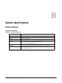
B
System Specifications
Physical Design
Chassis Dimensions
Table B-1.
Chassis Dimensions
Parameter
Specifications
Height
22.7 inches (57.66 cm)
Width
17.4 inches (37.58 cm)
Depth
14.4 inches (44.20 cm)
Weight
55 lbs (24.95 kg) with factory installed components
152.27 lbs (69.07 kg) fully loaded
Mounting
Integral rack mount strips for front mounting in a standard 19-inch rack.
Clearance required
Front: 18-inches (46 cm)
Rear: 20-inches (51 cm)
Installing and Maintaining the C300 System
63
www.dell.com | support.dell.com
Component Dimensions
Table B-2.
Component Dimensions
Component
Length (in)
Width (in)
Depth (in)
Weight (lb)
48-port 1G Line Card
15.25
13.75
1.75
5.31
4-port 10G XFP Line Card
15.25
13.75
1.75
5.31
8-port 10G XFP Line Card
15.25
13.75
1.75
5.31
8-port 1G SFP+ Line Card
15.25
13.75
1.75
5.31
48-port 1G SFP Line Card
15.25
13.75
1.75
5.31
48 Port 10/100/1GE-POE+
15.25
13.75
1.75
5.31
48-port 1G PoE Line Card
15.25
13.75
1.75
5.585
46-port FlexMedia Line Card
15.25
13.75
1.75
5.31
46-port FlexMedia PoE Line Card
15.25
13.75
1.75
5.31
C300 RPM
15.25
13.75
1
5.275
Fan Tray
13
1.125
16.125
8.51
Supply Unit
11.75
1.875
5.625
5.065
Line Card Blank Panel
15.25
13.75
1.75
2.94
RPM Blank Panel
15.25
13.75
1
2.75
PSU Blank Panel
11.25
1.875
5.625
1.08
System Specifications
Table B-3.
Parameter
Specifications
Nominal Input Voltage
100-240 VAC 50/60 Hz
Maximum AC Power Supply Input Current (Based on
1200 W output for 100/120 V and 1600 W output 200/
240 V lines)
14 A @ 100 V per AC Power Supply
11 A @ 120 VAC per AC Power Supply
9 A @ 200 VAC per AC Power Supply
7 A @ 240 VAC per AC Power Supply
Maximum System Power Input
9,667 KVA @ 100/120 V
12,596 KVA @ 200/240 V
Maximum Power Consumption
2,707 W @ 100/120 V
2,726 W @ 200/240 V
Maximum Thermal Output at 100/120 V
Maximum Thermal Output at 200/240 V
9,235 BTU/hour
9,299 BTU/hour
Table B-4.
64
|
AC Power System Specifications - Power Supply 1600W-AC
AC Power System Specifications - Power Supply 1200W-AC
Parameter
Specifications
Nominal Input Voltage
100-240 VAC 50/60 Hz
System Specifications
Table B-4.
AC Power System Specifications - Power Supply 1200W-AC
Maximum AC Power Supply Input Current (Based on
1200 W output for 100/120 V and 1600 W output 200/
240 V lines)
14 A @ 100 V per AC Power Supply
11 A @ 120 VAC per AC Power Supply
7 A @ 200 VAC per AC Power Supply
6 A @ 240 VAC per AC Power Supply
Maximum System Power Input
8,274 KVA @ 100/120 V
8,088 KVA @ 200/240 V
Maximum Power Consumption
2,361 W @ 100/120 V
2,175 W @ 200/240 V
Maximum Thermal Output at 100/120 V
Maximum Thermal Output at 200/240 V
8,055 BTU/hour
7,420 BTU/hour
Component Power Requirements
Table B-5.
Component Power Requirements
Component
Maximum Watts
48 Port 10/100/1GE-POE+
105W
48-port 10/100/1GELine Card
100W
4-port 10G XFP Line Card
120W
8-port 10G XFP Line Card
120W
8-port 10G SFP+ Line Card
120W
48-port 1G SFP Line Card
130W
48-port 10/100/1GE PoE Line Card
100W
46-port FlexMedia Line Card
120W
46-port FlexMedia PoE Line Card
120W
C300 RPM
100W
Fixed speed fan tray
85W
Variable speed fan tray
200W
Power Supply Unit 1200W-AC
1200W
Power Supply Unit 1600W-AC
1200W (low-line) 1600W (high-line)
NOTE: The listed requirement for the PoE version of line cards excludes the required power for PoE, as that
requirement is a function of the number and type of PoE devices connected.
NOTE: Additional components may be available for your system, other than those included in the above table.
Refer to www.force10networks.com/support/ for the latest information.
System Specifications
|
65
www.dell.com | support.dell.com
Agency Compliance
The C300 system is designed to comply with the following requirements.
USA Federal Communications Commission (FCC) Statement
This equipment has been tested and found to comply with the limits for a Class A digital device, pursuant to Part 15 of the FCC rules. These
limits are designated to provide reasonable protection against harmful interference when the equipment is operated in a commercial
environment. This equipment generates, uses, and can radiate radio frequency energy. If it is not installed and used in accordance to the
instructions, it may cause harmful interference to radio communications. Operation of this equipment in a residential area is likely to cause
harmful interference, in which case users will be required to take whatever measures necessary to correct the interference at their own expense.
Properly shielded and grounded cables and connectors must be used in order to meet FCC emission limits. Dell Networking is not responsible
for any radio or television interference caused by using other than recommended cables and connectors or by unauthorized changes or
modifications in the equipment. Unauthorized changes or modification could void the user’s authority to operate the equipment.
This device complies with Part 15 of the FCC Rules. Operation is subject to the following two conditions: (1) this device may not cause
harmful interference, and (2) this device must accept any interference received, including interference that may cause undesired operation.
Canadian Department of Communication Statement
European Union EMC Directive Conformance Statement
This product is in conformity with the protection requirements of EU Council Directive 2004/108/EC on the approximation of the laws of the
Member States relating to electromagnetic compatibility. Force 10 Networks can not accept responsibility for any failure to satisfy the protection
requirements resulting from a non-recommended modification of this product, including the fitting of non-Dell Networking option cards.
This product has been tested and found to comply with the limits for Class A Information Technology Equipment according to CISPR 22/
European Standard EN 55022. The limits for Class A equipment were derived for commercial and industrial environments to provide reasonable
protection against interference with licensed communication equipment.
CAUTION: This is a Class A product. In a domestic environment, this device may cause radio interference,
in which case, the user may be required to take adequate measures.
European Community Contact
Dell Force10, EMEA - Central
Dahlienweg 19
66265 Heusweiler
Germany
http://www.force10networks.com/german/
Tel: +49 172 6802630
Email: EMEA Central Sales
Japan: VCCI Compliance for Class A Equipment
66
|
System Specifications
This is Class A product based on the standard of the Voluntary Control Council For Interference by Information Technology Equipment
(VCCI). If this equipment is used in a domestic environment, radio disturbance may arise. When such trouble occurs, the user may be required
to take corrective actions.
WARNING: AC cords are for use with Dell Networking equipment only. Do not use Dell Networking AC cords with any
unauthorized hardware.
Korea (MIC certification)
Korea Certification
Korea Information
Safety Standards and Compliance Agency Certifications
• CUS UL (60950-1, 1st Edition)
System Specifications
|
67
www.dell.com | support.dell.com
• CSA 60950-1-03, 1st Edition
• EN 60950-1, 1st Edition
• EN 60825-1, 1st Edition
• EN 60825-1 Safety of Laser Products—Part 1: Equipment Classification Requirements and User’s
Guide
• EN 60825-2 Safety of Laser Products—Part 2: Safety of Optical Fibre Communication Systems
• FDA Regulation 21CFR 1040.10 and 1040.11
Electromagnetic Compatibility (EMC)
Emissions
• Australia/New Zealand: AS/NZS CISPR 22: 2006, Class A
• Canada: ICES-003, Issue-4, Class A
• Europe: EN55022 2006 (CISPR 22: 2006), Class A
• Japan: VCCI V3/ 2007.04 Class A
• USA: FCC CFR47 Part 15, Subpart B, Class A
Immunity
• EN 300 386 V1.3.3: 2005 EMC for Network Equipment
• EN 55024 1998 + A1: 2001 + A2: 2003
•
•
•
•
•
•
•
EN 61000-3-2 Harmonic Current Emissions
EN 61000-3-3 Voltage Fluctuations and Flicker
EN 61000-4-2 ESD
EN 61000-4-3 Radiated Immunity
EN 61000-4-4 EFT
EN 61000-4-5 Surge
EN 61000-4-6 Low Frequency Conducted Immunity
Product Recycling and Disposal
This switch must be recycled or discarded according to applicable local and national regulations. Dell
Networking encourages owners of information technology (IT) equipment to responsibly recycle their
equipment when it is no longer needed. Dell Networking offers a variety of product return programs and
services in several countries to assist equipment owners in recycling their IT products.
Waste Electrical and Electronic Equipment (WEEE) Directive for Recovery, Recycle and Reuse of IT and Telecommunications
Products
Dell Networking switches are labeled in accordance with European Directive 2002/96/EC concerning
waste electrical and electronic equipment (WEEE). The Directive determines the framework for the
return and recycling of used appliances as applicable throughout the European Union. This label, as
68
|
System Specifications
shown in Figure B-1, is applied to various products to indicate that the product is not to be thrown away,
but rather reclaimed upon end of life per this Directive.
Figure B-1.
The European WEEE Symbol
In accordance with the European WEEE Directive, electrical and electronic equipment (EEE) is to be
collected separately and to be reused, recycled, or recovered at end of life. Users of EEE with the WEEE
marking per Annex IV of the WEEE Directive, as shown above, must not dispose of end of life EEE as
unsorted municipal waste, but use the collection framework available to customers for the return,
recycling and recovery of WEEE. Customer participation is important to minimize any potential effects
of EEE on the environment and human health due to the potential presence of hazardous substances in
EEE.
Dell Networking products, which fall within the scope of the WEEE, are labeled with the crossed-out
wheelie-bin symbol, as shown above, as required by WEEE.
For information on Dell Networking product recycling offerings, see the WEEE Recycling instructions
on iSupport.
For more information, contact the Dell Networking Technical Assistance Center (TAC) (see Contacting
the Technical Assistance Center on page 55).
For California:
Perchlorate Material — Special handling may apply.
See: http://www.dtsc.ca.gov/hazardouswaste/perchlorate
The foregoing notice is provided in accordance with California Code of Regulations Title 22, Division
4.5 Chapter 33. Best Management Practices for Perchlorate Materials.
System Specifications
|
69
70
|
System Specifications
www.dell.com | support.dell.com
C
Contacting Technical Support
The iSupport Website
iSupport provides a range of documents and tools to assist you with effectively using Dell Networking
equipment and mitigating the impact of network outages. Through iSupport you can obtain technical
information regarding Dell Networking products, access to software upgrades and patches, and open and
manage your Technical Assistance Center (TAC) cases. Dell Networking iSupport provides integrated,
secure access to these services.
Accessing iSupport Services
The URL for iSupport is www.force10networks.com/support/. To access iSupport services you must have
a userid and password. If you do not have one, you can request one at the website:
On the Dell Networking iSupport page, click the Account Request link.
2 Fill out the User Account Request form, and click Send. You will receive your userid and password
by E-mail.
3 To access iSupport services, click the Log in link, and enter your userid and password.
1
Contacting the Technical Assistance Center
How to Contact Dell
Networking TAC
Information to Submit When
Opening a Support Case
Log in to iSupport at www.force10networks.com/support/, and select the Service
Request tab.
• Your name, company name, phone number, and E-mail address
• Preferred method of contact
• Model number
• Serial Number (see Locating Serial Numbers)
• Software version number
• Symptom description
• Screen shots illustrating the symptom, including any error messages. These can include:
• Output from the show tech command or the show tech linecard {number} command.
• Output from the show trace command or the show trace linecard {number}
command.
• Console captures showing the error messages.
• Console captures showing the troubleshooting steps taken.
• Saved messages to a syslog server, if one is used.
Managing Your Case
Log in to iSupport, and select the Service Request tab to view all open cases and RMAs.
Contacting Technical Support
|
71
www.dell.com | support.dell.com
Downloading Software
Updates
Log in to iSupport, and select the Software Center tab.
Technical Documentation
Log in to iSupport, and select the Documents tab. This page can be accessed without
logging in via the Documentation link on the iSupport page.
Contact Information
E-mail: [email protected]
Web: www.force10networks.com/support/
Telephone:
US and Canada: 866.965.5800
International: 408.965.5800
Locating Serial Numbers
• The chassis serial number is below the barcode on the sticker on the back of the chassis.
• The serial numbers for the RPM, line cards, fan tray, and supply units are below the barcode on the
sticker on the front of each component.
Requesting a Hardware Replacement
To request replacement hardware, follow these steps:
Step
1
Task
Determine the part number and serial number of the component. To list the numbers for all components installed in
the chassis, use the show inventory command.
NOTE: The serial numbers of fan trays and AC supplies will not appear in the hardware inventory listing. Check
the failed component for the attached serial number label.
NOTE: Quickly reinsert the fan tray back into the chassis once you have noted the serial number.
2
Request a Return Materials Authorization (RMA) number from TAC by opening a support case. Open a support case
by:
• Using the Create Service Request form on the iSupport page (see Contacting the Technical Assistance Center).
• Contacting Dell Networking directly by E-mail or by phone (see Contacting the Technical Assistance Center).
Provide the following information when using E-mail or phone:
• Part number, description, and serial number of the component.
• Your name, organization name, telephone number, fax number, and e-mail address.
• Shipping address for the replacement component, including a contact name, phone number, and e-mail address.
• A description of the failure, including log messages. This generally includes:
• the show tech command output
• the show trace and show trace hardware command output
• for line card issues, the show trace hardware linecard command output
• console captures showing any error messages
• console captures showing the troubleshooting steps taken
• saved messages to a syslog server, if one is used
• The support representative will validate your request and issue an RMA number for the return of the component.
72
|
Contacting Technical Support
Step
3
Task
When returning an RMA component, follow the packing and shipping directions in the Return Instructions
document that accompanies the replacement component. Alternatively, contact your TAC representative for a
replacement copy.
Generally, you are instructed to return the RMA component in the original packaging material provided with the
replacement, and to label the package with the RMA number.
Contacting Technical Support
|
73
www.dell.com | support.dell.com
74
|
Contacting Technical Support
Printed in the U.S.A.
w w w. d e l l . c o m | s u p p o r t . d e l l . c o m