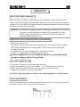
1
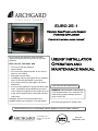
EURO 25 -1 Vented Gas Fireplace Insert Heating Appliance For use with natural gas or propane* Do not store or use gasoline or other flammable vapors and liquids in the vicinity of this or any other appliance. WHAT TO DO IF YOU SMELL GAS: ∗ Do not try to light any appliance ∗ Open windows ∗ Do not touch any electrical switch; do not use any phone in your building ∗ Extinguish any open flame ∗ Immediately call your gas supplier from a neighbor’s phone. Follow the gas supplier’s instructions ∗ If you cannot reach your gas supplier, call the fire department. ∗ Do not use this appliance if any part has been under water. Immediately call a qualified service technician to inspect the appliance and to replace any part of the control system and any control that has been under water. Installation and service must be performed by a qualified installer, service agency or the gas supplier. USERS’ INSTALLATION OPERATION AND MAINTENANCE MANUAL NOT FOR USE WITH SOLID FUEL WARNING: If the information in this manual is not followed exactly, fire or explosion may result causing property damage, personal injury or loss of life. *Conversion Kit Required for Propane Use INSTALLER: Please leave this manual with the appliance owner for future reference. 7116 Beatty Drive Mission, BC V2V 6B4 Canada 200-0215 FEBRUARY 2005 INTRODUCTION Congratulations on purchasing the Archgard Euro-25 Gas Fireplace Insert Heater! The Euro-25 is one of the most advanced gas heating appliances on the market. It is designed using the latest technology and manufactured to the highest quality. Some of the many features of the Euro 25 are: Realistic Flames Three-dimensional flames similar to a real wood fire Heater Classification Classified as a heating appliance, therefore, can be operated continuously for zone heating High Efficiency High efficiency means less expensive to operate Adjustable Heat The flame aesthetics and heat output can be adjusted to suit the owner’s moods and heating needs Solid Construction Constructed mainly of 16- and 18-gauge, satin-coated steel for long life and durability Please read this manual carefully prior to installation and operation of the appliance. Proper installation, operation and maintenance of the appliance will provide you with many years of enjoyment. We recommend that you record the following information: Fireplace Model Number: EI - 25-1 Serial Number: Date of Installation: Type of Gas Used by the Fireplace: Dealer’s Name & Address: Dealer’s Phone Number: Natural Gas Propane EURO 25 -1 4 STATE OF MASSACHUSETTS REQUIREMENTS 5.08: Modifications to NFPA-54, Chapter 10 (2) Revise 10.8.3 by adding the following additional requirements: (a) For all side wall horizontally vented gas fueled equipment installed in every dwelling, building or structure used in whole or in part for residential purposes, including those owned or operated by the Commonwealth and where the side wall exhaust vent termination is less than seven (7) feet above finished grade in the area of the venting, including but not limited to decks and porches, the following requirements shall be satisfied: 1. INSTALLATION OF CARBON MONOXIDE DETECTORS. At the time of installation of the side wall horizontal vented gas fueled equipment, the installing plumber or gasfitter shall observe that a hard wired carbon monoxide detector with an alarm and battery backup is installed on the floor level where the gas equipment is to be installed. In addition, the installing plumber or gasfitter shall observe that a battery operated or hard wired carbon monoxide detector with an alarm is installed on each additional level of the dwelling, building or structure served by the side wall horizontal vented gas fueled equipment. It shall be the responsibility of the property owner to secure the services of qualified licensed professionals for the installation of hard wired carbon monoxide detectors a. In the event that the side wall horizontally vented gas fueled equipment is installed in a crawl space or an attic, the hard wired carbon monoxide detector with alarm and battery back-up may be installed on the next adjacent floor level. b. In the event that the requirements of this subdivision can not be met at the time of completion of installation, the owner shall have a period of thirty (30) days to comply with the above requirements; provided, however, that during said thirty (30) day period, a battery operated carbon monoxide detector with an alarm shall be installed. 2. APPROVED CARBON MONOXIDE DETECTORS. Each carbon monoxide detector as required in accordance with the above provisions shall comply with NFPA 720 and be ANSI/UL 2034 listed and IAS certified. 3. SIGNAGE. A metal or plastic identification plate shall be permanently mounted to the exterior of the building at a minimum height of eight (8) feet above grade directly in line with the exhaust vent terminal for the horizontally vented gas fueled heating appliance or equipment. The sign shall read, in print size no less than one-half (1/2) inch in size, "GAS VENT DIRECTLY BELOW. KEEP CLEAR OF ALL OBSTRUCTIONS". 4. INSPECTION. The state or local gas inspector of the side wall horizontally vented gas fueled equipment shall not approve the installation unless, upon inspection, the inspector observes carbon monoxide detectors and signage installed in accordance with the provisions of 248 CMR 5.08(2)(a)1 through 4. (b) EXEMPTIONS: The following equipment is exempt from 248 CMR 5.08(2)(a)1 through 4: 1. The equipment listed in Chapter 10 entitled "Equipment Not Required To Be Vented" in the most current edition of NFPA 54 as adopted by the Board; and 2. Product Approved side wall horizontally vented gas fueled equipment installed in a room or structure separate from the dwelling, building or structure used in whole or in part for residential purposes. (c) MANUFACTURER REQUIREMENTS - GAS EQUIPMENT VENTING SYSTEM PROVIDED. When the manufacturer of Product Approved side wall horizontally vented gas equipment provides a venting system design or venting system components with the equipment, the instructions provided by the manufacturer for installation of the equipment and the venting system shall include: 1. Detailed instructions for the installation of the venting system design or the venting system components; and 2. A complete parts list for the venting system design or venting system. (d) MANUFACTURER REQUIREMENTS - GAS EQUIPMENT VENTING SYSTEM NOT PROVIDED. When the manufacturer of a Product Approved side wall horizontally vented gas fueled equipment does not provide the parts for venting the flue gases, but identifies "special venting systems", the following requirements shall be satisfied by the manufacturer: 1. The referenced "special venting system" instructions shall be included with the appliance or equipment installation instructions; and 2. The "special venting systems" shall be Product Approved by the Board, and the instructions for that system shall include a parts list and detailed installation instructions. (e) A copy of all installation instructions for all Product Approved side wall horizontally vented gas fueled equipment, all venting instructions, all parts lists for venting instructions, and/or all venting design instructions shall remain with the appliance or equipment at the completion of the installation. For the State of Massachusetts, installation and repair must be done by a plumber or gasfitter licensed in the Commonwealth of Massachusetts. For the State of Massachusetts, flexible connectors shall not exceed 36 inches in length. The State of Massachusetts requires the installation of a carbon monoxide alarm in accordance with NFPA 720 and a CO alarm with battery back up in the same room where the gas appliance is TABLE OF CONTENTS Page Caution & Safety Information 5 General Information 6 Appliance Description and Dimensions 7 Installation Instructions 8 Log Placement 15 Operation Instructions 20 Maintenance 22 Troubleshooting Instructions 23 Servicing 25 APPENDIX A - Installation Into Vented Gas Fireplaces 28 Suitable Host Fireplaces / Specific Installation Instructions 32 Important Information Form 37 Warranty 38 Replacement Parts 39 Notes 40 Warranty Registration Card 41 EURO 25 -1 6 CAUTION Due to high temperatures, the appliance should be located out of traffic and away from furniture and draperies. Children and adults should be alerted to the hazards of high surface temperature and stay away to avoid burns or clothing ignition. Young children should be carefully supervised when they are in the same room as the appliance. Clothing or other flammable material should not be placed on or near the appliance. Any parts removed or opened for servicing of the appliance must be properly replaced prior to operating the appliance. The appliance must be inspected before use and at least annually by a qualified service person. More frequent cleaning may be required due to excessive lint from carpeting, bedding material, etc. It is imperative that the control compartments, burners and circulating air passageways for the appliance be kept clean. SAFETY FOR YOUR SAFETY - Do not install or operate your Archgard Euro 25 Gas Fireplace Insert Heater without reading and understanding this manual. Any installation or operational deviation from this instruction manual voids the Archgard Industries Ltd. Warranty and may prove hazardous. This appliance must be installed by a qualified gas installer and the installation must conform to the installation codes. Provide adequate clearance around air openings of the appliance. Never obstruct front openings. Provide adequate clearances for proper operation and servicing of the appliance. This appliance must be properly connected to an approved venting system and must not be connected to a chimney flue serving a separate solid fuel burning appliance. EURO 25 -1 7 GENERAL INFORMATION APPLIANCE CERTIFICATION This appliance is tested and certified to the following U.S. and Canadian gas appliance standards. - ANSI Z 21.88b-2003 / CSA 2.33b-2003, Vented Gas Fireplace Heater - CAN/CGA-2.17-M91, Gas-Fired Appliances for Use at High Altitudes. Please contact Archgard Industries Ltd., if you have any questions regarding the certification of these appliances. INSTALLATION CODES This appliance must be installed by a qualified gas appliance installer. The installation must conform with the local codes or, in the absence of local codes, with the current National Fuel Gas Code, ANSI Z223.1/ NFPA 54, in the US or Installation Code, CAN/CGA-B149, in Canada. Electrical connections and grounding must conform with local code, or current National Electrical code, ANSI/NFPA No. 54, in the U.S. and in Canada, the current Canadian Electrical Code, CSA C22.1. This appliance is certified for installation in a bedroom or a bedsitting room and conforms to CR89-001. SPECIFICATIONS Natural Gas (NG) Propane (LP) 1.7 - 3.5 in. w.c. (0.4 - 0.9 kPa) 6.3 - 10.0 in. w.c. (1.6 - 2.5 kPa) Minimum Supply Pressure for Purpose of Input Adjustment 4.5 in. w.c. (1.2 kPa) 11.0 in. w.c. (2.8 kPa) Maximum Supply Pressure for Purpose of Input Adjustment 14.0 in. w.c. (3.6 kPa) 14.0 in. w.c. (3.6 kPa) Cap #45 DMS (2.08 mm dia.) Cap #55 DMS (1.32 mm dia.) 15,000 - 20,000 BTU/hr (4.4 - 5.8 kW) 16,000 -20,000 BTU/hr (4.6 - 5.8 kW) 0 - 4,500 ft. (0 - 1372 m) 0 - 4,500 ft. (0 - 1372 m) 3/16 in. (5 mm) Fully Open Manifold Pressure Orifice Size Nominal Input Rating Altitude Primary Air Opening HIGH ALTITUDE INSTALLATION When installing this appliance beyond 4500 ft. (1372 m) above sea level, the appliance must be properly de-rated and installed according to local codes, in the absence of local codes, with the current National Fuel Gas Code, ANSI Z223.1/ NFPA 54, in the U.S. or Installation Code, CAN/CGA-B149, in Canada. EURO 25 -1 8 APPLIANCE DESCRIPTION & DIMENSIONS FRONT VIEW SURROUND TOP LOUVERS BAY GLASS DOOR CONVECTION FAN SPEED CONTROL GAS VALVE SPARKER REMOVABLE CONTROL COVER APPLIANCE DIMENSIONS I J A G D K B C F E H A B C D E 30 ¼” 23” 15 ¼” 11 ¼” 4” (768 mm) (584 mm) (387 mm) (286 mm) (102 mm) F G H I J 19 ¼” 5” 5 ¾” 24 ¼” 16 ¼” Flue Collar - 4” (102 mm) diameter (489 mm) (127 mm) (146 mm) (616 mm) (413 mm) K Variable from 2 ½” (63.5 mm) to -3 ½” (-89 mm) EURO 25 -1 9 INSTALLATION INSTRUCTIONS CLEARANCES TO COMBUSTIBLES SIDE VIEW Combustible mantle allowed in shaded area. Mantle extension may be increased 1” (25 mm) for each additional 1” (25 mm) increase in clearance height. Minimum Height From Bottom of Appliance: 36” (915 mm) Minimum Height From Top of Surround: 13” (330 mm) 6” (152 mm) Leveling leg Non-combustible hearth is not required.* * Observe building codes; the codes may require a non-combustible hearth. TOP VIEW 3” (76 mm) 3” (76 mm) Clearances to Surround Sidewalls or Mantle Supports CAUTION: This appliance is designed for use in any masonry, factory-built wood burning and specific zero-clearance vented gas fireplaces (Due to constant additions, contact Archgard Industries for an updated list of suitable gas fireplaces). This appliance cannot be enclosed with combustible material and used as a built-in gas fireplace. EURO 25 -1 10 INSTALLATION INSTRUCTIONS - Continued MINIMUM MASONRY FIREPLACE DIMENSIONS SIDE VIEW TOP VIEW Y Z 12” (305 mm) X 17” (432 mm) 19 ½” (495 mm) 25” (635 mm) The standard flue adapter will fit if X is more than 5 ¾”. It will also fit if X is less than 5 ¾” but Y is higher than 8” (See ‘Flue connector, offset vent’ diagram) Flue connector straight-up vent Flue connector offset vent Flue connector straight-up vent Flue connector offset vent EURO 25 -1 11 INSTALLATION INSTRUCTIONS - Continued MINIMUM ZERO-CLEARANCE WOOD BURNING FIREPLACE DIMENSIONS SIDE VIEW TOP VIEW Y Z 12” (305 mm) X 17” (432 mm) 15 ¼” (387 mm) 25” (635 mm) The standard flue adapter will fit if X is more than 5 ¾”. It will also fit if X is less than 5 ¾” but Y is higher than 8” (See ‘Flue connector, offset vent’ diagram) Flue connector straight-up vent Flue connector offset vent Flue connector straight-up vent Flue connector offset vent EURO 25 -1 12 INSTALLATION INSTRUCTIONS - Continued To install the Euro 25 into a vented gas fireplace, see APPENDIX A (page 24) for installation instructions. PRECAUTIONS • This appliance must be installed by a qualified gas installer and the installation must conform to the • • • • installation codes. This appliance needs fresh air for safe operation and must be installed so there are provisions for adequate combustion and ventilation air. Provide adequate clearance around air openings of the appliance. Never obstruct front openings. Provide adequate clearances for proper operation and servicing of the appliance. This appliance must be properly connected to a suitable venting system and must not be connected to a chimney flue serving a separate solid fuel burning appliance. This appliance is equipped with a three-prong (grounding) plug for your protection against shock hazard and should be plugged directly into a properly grounded three-prong receptacle. VENTING The appliance is equipped with a vent safety shutoff system and a safety control system designed to protect against improper venting of combustion products. The appliance will not function without being connected to a proper venting system. The draft hood must be installed in the same room as the atmospheric pressure zone serving the unit for combustion air. WARNING: Operation of this appliance when not connected to a properly installed and maintained venting system or tampering with the vent shut-off system can result in carbon monoxide (CO) poisoning and possible death. This appliance must not be connected to a chimney flue serving a separate solid fuel burning appliance. The appliance may be vented using 4 in. diameter aluminum or stainless steel flexible gas liner running inside a masonry chimney or the flue of the factory-built fireplace. The vent system must be properly terminated with a suitable vent cap. The liner must form a complete connection from the flue collar to the vent cap. Follow the vent component manufacturer’s instruction. Also check with local gas authorities for proper venting methods and procedures. Connecting the Vent Liner to the Appliance Run the flexible gas liner down the chimney or flue. The appliance has a detachable flue adapter plate for ease of installation. Connect the the liner to the flue connector plate and fasten with screws and a 4” gear clamp. Before placing the appliance into the fireplace, check the hearth of the fireplace to see if it is level with the front of the fireplace. If it is not, measure the depth of the hearth. Loosen the three screws of the leveling “L” bracket at the back of the appliance. Lower it to the measurement obtained and tighten the screws. Make sure the gas and electrical supply line are properly connected to the appliance. Slide the appliance into the fireplace, and at the same time, slide the flue connector plate back onto the top of the appliance. Check the leveling of the appliance and attach the faceplate to the appliance before sliding the appliance all the way into the fireplace. EURO 25 -1 13 INSTALLATION INSTRUCTIONS - Continued VENTING - Continued Caution: Make sure the flue adapter plate is not too far back, or the appliance will not vent properly. x X = ¼” minimum The arms can also be bent up and out of the way if the adapter plate is forward enough to interfere with the surround. The adapter plate must completely close with the appliance top plate. GAS CONNECTIONS Have your gas supplier or a qualified gas fitter run a gas supply line to the gas fireplace. The line must be properly sized and fitted according to the installation codes. Up stream of the supply connection, the fitter shall provide an accessible manual shut-off valve. CAUTION: The appliance and its individual shutoff valve must be disconnected from the gas supply piping system during any pressure testing of that system at test pressures in excess of ½ psig (3.5 kPa). The appliance must be isolated from the gas supply piping system by closing its individual manual shutoff valve during any pressure testing of the gas supply piping system at test pressures equal to or less than ½ psig (3.5 kPa). Failure to do so will damage the appliance’s gas valve. Such damage is not covered by the manufacturer’s warranty. Check for proper gas supply pressure by loosening the set screw on supply pressure tap (marked IN) on the gas valve with a small flat tip screw driver and placing a test gauge on the tap. The minimum permissible gas supply pressure is 4.5 in. w.c. (1.2 kPa) for natural gas and 11.0 in. w.c. (2.8 kPa) for propane. Maximum gas supply pressure should never exceed 14.0 in. w.c. (3.6 kPa) or ½ psig. for both natural gas and propane. BE SURE TO TIGHTEN THE PRESSURE TAP SET SCREW AFTER CHECKING THE PRESSURE, AND CHECK FOR GAS LEAKS. Before connecting the appliance to the gas supply line, double check that the appliance you have purchased is designed for the gas type you are using. The gas type markings are located on the certification label and also on the tag attached to the appliance’s gas valve. Adequate clearance for proper installation and checking of the gas connections must be provided. All gas connections must be checked for gas leaks. EURO 25 -1 14 INSTALLATION INSTRUCTIONS - Continued ATTACHMENT OF FIREPLACE SURROUND The surround has four hooks that clip onto the sides of the appliance. Make sure the surround sits evenly with the front of the fireplace. After the surround is properly installed, the bottom edge of the centre section of the surround is about ¾” from the top of the appliance. THE SPILL SWITCH IS CONNECTED TO THE APPLIANCE (FACTORY-WIRED) If needed, two securing brackets are provided to stabilize the appliance in shallow zeroclearance fireplaces. Screw these to the top of the appliance and to the face of the host fireplace. Use the holes on the bracket that best suit your application. EURO 25 -1 15 INSTALLATION INSTRUCTIONS - Continued GLASS DOOR WARNING: Glass door is fragile. Do not strike or abuse glass. Do not operate appliance with broken glass. Do not attempt to fix a broken glass door. It must be replaced with an identical one from the manufacturer. Do not attempt to remove the glass door when the appliance is hot. Removing the Glass Door Remove the louvers by lifting and unhooking it off the appliance. Remove the control cover by sliding it off the bottom door assembly. There is a buckle latch located in the bottom centre lift the lever on the back of the latch to release it. Unhook the latch from the bottom of the door and swing the bottom of the door towards you. Lift up the door to unhook it from the body. Place the door at a safe location where it cannot be scratched or damaged. Replacing the Glass Door The reverse procedure of Removing the Glass Door. LOUVRES DOOR HOOKS BUCKLE LATCH CONTROL COVER PLACEMENT OF BRICK PANELS Remove the ‘Z’ shape panel clips on the left and right side of the firebox. Carefully place the panels into the firebox. There are three panels: a center, a left and a right panel. Place the center panel to the back of the firebox. The tapered end of the side panels are towards the back of the firebox. Tilt the panels to pass them through the door opening. Slide the bottom of the panels in place first, and then tilt the panels upright into position. Push the panel to the back. Re-attach the ‘Z’ shape panel clips to the firebox. LEFT PANEL RIGHT PANEL PANEL CLIP PANEL CLIP CENTER PANEL EURO 25 -1 16 LOG PLACEMENT The following pages outline the steps for correctly placing the logs and platinum embers in your Euro 25-1. Upon completion, the logs and embers should look as shown in the photo below. WARNING: Do not place the logs or branches in any configuration other than the one shown. A fire, explosion or excessive carbon monoxide (CO) may result, causing property damage, personal injury or loss of life. STEP 1. PLATINUM EMBERS WARNING : Do not place the embers directly on the burner ports. A fire, explosion or excessive carbon monoxide (CO) may result, causing property damage, personal injury or loss of life. Do not add more or different materials to the burner than the amount and type supplied with the unit. EURO 25 -1 17 LOG PLACEMENT - Continued STEP 2 - Locate log #136 and place onto rear log support using locator pins and pre-drilled holes in log. Log will sit as shown in the photo below. PINS FOR LOG # 136 STEP 3 - Locate log #137 and place onto the left side of the burner using locator pins and pre-drilled holes in log. Log will sit as shown in photo below. PIN HOLES FOR LOG # 137 EURO 25 -1 18 LOG PLACEMENT - Continued STEP 4 - Locate log #140 and place onto centre of burner using the locator pins and pre-drilled holes in log. Log should sit as shown in photo below. PIN HOLES FOR LOG # 140 STEP 5 - Locate log #141 and place onto right side of burner using the locator pins and pre-drilled holes in log. Log should sit as shown in photo below. PIN HOLES FOR LOG # 141 EURO 25 -1 19 LOG PLACEMENT - Continued STEP 6 - Locate log #135 and place onto rear log using the locator pins and pre-drilled holes in log. Log should sit as shown in photo below. PIN HOLE FOR LOG # 135 STEP 7 - Locate log #139 and place onto rear log using the locator pins and pre-drilled holes in log. Log should sit behind right grate tine as shown in photo below. PIN FOR LOG # 139 EURO 25 -1 20 LOG PLACEMENT - Continued STEP 8 - Locate log #138 and place onto rear log using the locator pins and pre-drilled holes in log. Log should sit behind left grate tine as shown in photo below. PIN HOLE FOR LOG # 138 FINAL LOG PLACEMENT - Please note that all logs should be placed exactly as shown. EURO 25 -1 21 OPERATION INSTRUCTIONS FOR YOUR SAFETY, READ BEFORE LIGHTING INITIAL OPERATION • Check that the appliance is properly vented and connected to the gas supply. • Check that the logs and branches are properly placed. • Check all external parts, such as grills, door and control cover are properly attached and fastened. NOTE : When operated for the first few times, the appliance will emit odors and fumes. This is due to the evaporation of oils and solvents used in fabricating the appliance. Close off the room to the rest of the house and open all windows. Keep the room well ventilated. Operate the appliance continuously on high setting for at least 4 to 6 hours. This will ‘burn-in’ the appliance and reduce the chance of odors and fumes reoccurring the next time the appliance is used. You may have to repeat the ‘burn-in’ procedure a few times. WARNING : If you do not follow these instructions exactly, a fire or explosion may result, causing property damage, personal injury or loss of life. A. This appliance has a pilot which must be lit by hand using the sparker located next to the appliance valve controls. When lighting the pilot, follow the start-up procedures exactly. B. BEFORE LIGHTING, smell all around the appliance area for gas. Be sure to smell next to the floor, because some gases are heavier than air and will settle on the floor. IF YOU SMELL GAS, follow the instruction on the front cover of this manual. C. Use only your hand to push in or turn the gas control knob. Never use tools. If the knob will not push in or turn by hand, don’t try to repair it. Call a qualified service technician. Force or attempted repair may result in a fire or explosion. D. Do not use this appliance if any part has been under water. Immediately call a qualified service technician to inspect the appliance and to replace any part of the control system and any gas control which has been under water. EURO 25 -1 22 OPERATION INSTRUCTIONS - Continued START-UP PROCEDURE 1. Set the thermostat, if present, to the lowest level. Set the flame adjustment knob to the HI position. Press slightly and turn the control knob clockwise 3 to the OFF position and wait 5 minutes; thus allowing any gases to escape which may have accumulated in the combustion chamber. Note: LP gases do not vent upward. Then follow step 2 and 3 to establish pilot. 2. Press slightly and turn control knob counterclockwise 4 to PILOT position; depress control knob and light pilot by repeatedly pressing the sparker. Venting of air may take place at the pilot prior to the flow of fuel gases. Once flame is established, hold knob depressed for approximately 60 sec. 3. Release knob. If pilot should go out, turn the control knob to OFF position and repeat steps 1, 2 and 3. Note: this will allow reset of INTERLOCK for proper lighting of pilot. 4. Press and turn control knob counterclockwise 4 to ON position. 5. Turn flame and heat adjustment knob to the desired comfort level from HIGH to LOW. 6. Turn thermostat to the desired comfort level or turn ON/OFF switch to the ON position. TEMPORARY SHUT-DOWN PROCEDURE 7. To turn off the main burner only, set the thermostat to the lowest setting or turn remote switch to OFF. Press and turn the knob clockwise 3 to PILOT position. COMPLETE SHUT-DOWN PROCEDURE 8. Press and turn the knob clockwise 3 to the OFF position. Flame and Heat Adjustment Knob Control Knob EURO 25 -1 23 MAINTENANCE CAUTION : Maintenance should only be conducted on a cold appliance. CLEANING THE APPLIANCE The exterior painted surfaces, glass and gold trims may be cleaned with a soft, non-abrasive cloth and water or a suitable, mild, non-abrasive cleaner. Regularly: • Clean and remove any lint accumulations or debris from the grills and in any • • • • combustion and convection air passageways. Keep the appliance area free from combustible materials, such as paper, wood, clothing, gasoline and flammable solids, liquids and vapors. Visually check the height and color of the burner and pilot flames. Check for unusual noise, odor and operation of the appliance. Check the vent terminal for any damage, or obstruction by plants or debris accumulation. Once a year: • Remove the glass door and clean the inside of the glass with specially formulated ceramic glass cleaner, and a non-abrasive cloth, available from your local dealer. • Carefully remove the logs and, if present, gently brush off any loose carbon deposits. This job is best done outside the house, wearing a dust mask.The logs are very fragile; take care not to break them. After cleaning, the logs must be replaced as per the instructions in this manual. Once a year, have a qualified service technician: • Completely inspect the appliance and the venting system. • Clean and remove any lint accumulations or debris in the firebox, on the burners, on the pilot, at the primary air opening, on the convection air blower and in any combustion and convection air passageways. • Check the safety system of the gas valve. WARNING: All parts removed or disturbed must be properly replaced after maintenance. Service and repair must be conducted by a qualified service person. If these instructions are not followed, a fire or explosion may result, causing property damage, personal injury or loss of life. EURO 25 -1 24 TROUBLESHOOTING Please check to make sure the instructions are followed exactly before attempting troubleshooting of the appliance. WARNING: Troubleshooting and servicing of gas and electrical devices of the appliance should only be conducted by a qualified service technician. SYMPTOM ACTION Pilot will not light after pressing the sparker many times. 1. When lighting the appliance for the first time after installation or after servicing, there is air in the gas line. It takes a while for all the air to purge out of the pilot before gas can reach the pilot and ignite. Remove the glass door and try lighting the pilot many times to purge the air. 2. Check to make sure the gas supply to the appliance is turned on and there is adequate gas supply pressure to the appliance. 3. Check for sparks between the spark electrode and the pilot head when the sparker is pressed. If there are no sparks: a. Check for broken or poor connection from the sparker to the electrode. b. Check for the spark shorting or arcing at other locations. c. Check for defective sparker. d. Check for defective spark electrode (cracked ceramic). 4. With the door removed, try lighting the pilot with a match. a. If air is blowing on the flame of the match, hold the control knob in at the ‘PILOT’ setting until all the air is purged out of the line. b. If there is no gas or air coming out of the pilot and there is gas pressure to the appliance, the pilot orifice may be blocked or the gas valve may be defective. 5. Check wiring and connections to spill switch. Pilot will not remain on after being lit. 1. Press the control knob all the way in. 2. Hold the control knob in for a longer period of time. 3. If you are trying to re-light the pilot immediately after you have shut-off the pilot, you have to wait a minute for the valve to reset. 4. Check to see if the pilot flame is large enough to reach and surround the thermocouple. If the flame is too small, check for correct gas supply pressure. If pressure is good, adjust the pilot flame size with the adjustment screw on the valve. If the flame cannot be adjusted, there might be some debris obstructing the pilot orifice, or a wrong size pilot orifice. 5. Check for proper millivolts of the thermocouple. The thermocouple should generate at least 30 mV or it is defective. 6. Check for defective gas valve. The main burner does not turn on with the pilot lit. 1. Check to make sure the control knob is turned to the ‘ON’ position. 2. Allow enough time for the pilot to heat up the thermopile to generate sufficient voltage to activate the valve. EURO 25 -1 25 TROUBLESHOOTING - Continued SYMPTOM ACTION The main burner does not turn on with 3. If using an optional thermostat, check to make sure the thermostat is set high enough the pilot lit. (continued) to turn on the appliance. 4. If using an optional remote switch, check that the remote switch or the thermostat is turned on. 5. Check for weak pilot flame. If flame is weak, check gas supply, check pilot flame adjustment and check for blockage of pilot orifice. 6. Check all connections to the valve for tight electrical contact. 7. Check for 400-500 mV from the thermopile with the burner off and 200-250 mV with the burner on. If the voltages are lower, the thermopile is defective. 8. Check for defective gas valve. 9. Look for blockages in ports next to pilot flame. 10. Check for poor connection of the thermocouple to the valve or through the spill switch. Wait for spill switch to cool before attempting to re-light the pilot. The main burner shuts off when the appliance is warm 1. 2. 3. 4. 5. 6. 7. This may be the normal operation of a wall thermostat installed to appliances. Check for good pilot flames on the thermopile (see page 24). Check for good voltage from the thermopile. Check for proper functioning of venting system. Check wire connections. Expansion from heat affects a loose connection Check the spill switch for correct ohms reading. Replace if required. Check for proper drafting of the appliance. Correct if drafting is occurring into the room. 8. Spill switch has tripped. (Reset by hand when appliance has cooled) Sooty deposits on the glass door. 1. If the flame is yellow and lazy, check for lint etc. around primary air shutter. Increase primary air by opening the primary air shutter if necessary. 2. Check for proper placement of the logs and branches. Ensure logs and burner are clean. See that section in the instruction manual. 3. Check for obstruction of the burner ports by the embers. See that section in the instruction manual. 4. Check for proper venting and blockage of the vent termination. 5. Check manifold pressure and clock input rating for over-firing. Sharp blue flames with flames lifting off the burner at the ends. 1. Too much primary air. Reduce primary air by closing the primary air shutter. During cold temperatures, some flame lifting may occur during start-up. (Follow primary air specified settings on Page 4). Convection blower does not turn on. 1. The convection fan is thermostatically controlled. It will only turn on when the appliance is warmed-up. This may take up to 15 minutes with the appliance on high. 2. Check for 120VAC electrical supply to the appliance. (Is the cord plugged in?) 3. Check for proper mounting of the thermal snap disc. 4. Check electrical connections. 5. Check for defective thermal snap disc. 6. Check for defective convection blower speed controller. 7. Check for defective convection blower. EURO 25 -1 26 SERVICING SERVICING UNDER WARRANTY Before servicing, read the terms and conditions of the Archgard warranty at the back of the manual. Contact the Archgard authorized dealer from which you have purchased the appliance and provide him with details of the problem and the installation information which the installer has filled out at the back of this manual. WARNING: Servicing of this appliance must be conducted by a qualified service technician. Improper servicing, adjustment or alteration of this appliance may cause property damage, personal injury or loss of life. All servicing should be conducted with the appliance cold. CHECKING SUPPLY AND MANIFOLD GAS PRESSURE • Remove the control cover. • The pressure test taps are located on the front of the valve. The supply pressure is marked ‘IN’ and the manifold pressure is marked ‘OUT’. There is also an arrow marking the direction of gas flow. • Loosen the set screw inside the tap with a ⅛” wide flat screw driver. • Connect a ¼” rubber tube to the tap and a pressure gauge. • Be sure to tighten the set screw inside the tap after you are finish taking pressure readings and check for gas leaks. ADJUSTING PRIMARY AIR • • • • The primary air shutter is located underneath the burner. Loosen the air shutter set screw with a Philips ‘+’ or a #3 Robertson ‘’ screwdriver. Rotate air shutter by hand. The primary air opening size can be easily seen. Tighten the air shutter set screw after adjustment. CAUTION: Adjust the primary air shutter only when the appliance is cool to the touch. PILOT ADJUSTMENT The pilot flame should fully envelop the thermocouple and thermopile with a strong blue cone flame. If a lazy flame is observed this could cause the unit to shut down. EURO 25 -1 27 SERVICING - Continued REPLACEMENT OF FAN • Disconnect the power to the appliance. • Remove the louvers, control cover door, brick panels, logs and burner. • Remove the firebox lower back. Remove the screws located at the back of the firebox. Take the lower firebox back out. Be careful not to damage the gasket. The fan is now visible. • Use a 11/32” hex socket and remove the three nuts holding the fan to the back of the firebox. Disconnect the spade connectors to the fan. Carefully remove the fan. • Reverse the above instructions to install the new fan WIRING DIAGRAM SPEED CONTROL 110°F (43ºC) N.O. THERMAL SNAP SWITCH LINE 120 VAC CONVECTION FAN NEUTRAL GROUND TO APPLIANCE VALVE CONNECTIONS C THERMOCOUPLE LEAD B D (1770C) SPILL SWITCH (MANUAL RESET) 350°F A PILOT ASSEMBLY A ELECTRODE B THERMOPILE C PILOT CAP D THERMOCOUPLE SUPPLY TUBE WIRE TO PIEZO (SPARKER) ON/OFF SWITCH ROBERTSHAW GAS CONTROL VALVE WIRING DIAGRAM. USED FOR EURO 25 INSERT. OPTIONAL REMOTE SWITCH OR THERMOSTAT EURO 25 -1 28 SERVICING - Continued REPLACING MAJOR GAS COMPONENTS If any of the major gas components need to be replaced, such as the pilot or the gas valve, we recommend replacing the complete gas component assembly. The assembly is designed to be quickly and easily replaced with minimal inconvenience to the customer. Once replaced, the service technician can repair the defective assembly safely and comfortably in his shop and with the right tools and test equipment. REPLACING GAS COMPONENT ASSEMBLY • Disconnect electricity to the appliance. • Remove the glass door and the logs. (see installation section) • Remove the burner tray by loosening and removing the two mounting screws located next to • • • • the two back log locating tabs. Shut of the gas to the appliance and disconnect the gas line to the appliance. If the appliance has a remote switch or thermostat, disconnect their wires at the front of the valve. Mark the wires for reassembly. Remove the firebox back, see “REPLACEMENT OF FAN” (Page 26) Remove the four screws holding the gas component assembly plate to the appliance. Gently slide the assembly forward out of the firebox. Replacing the assembly is the reverse of the above instructions. CHANGING MAIN BURNER ORIFICE • • • • • • • Remove the glass door, log set and the burner. Use a ½” wrench to loosen the orifice. Change the orifice. Attach the new orifice. Replace the burner and the log set. Test fire the appliance with the glass door off and check for gas leaks. Replace the glass door. CONVERTIBLE PILOT ORIFICE The pilot assembly is convertible to the type of gas being used, simply unscrew the body by using a 7/16” (11 mm) wrench turn a ¼ open then push the small metal tab across to the other side of the body and retighten. Call your local Authorized Archgard Dealer to purchase the correct fuel conversion kit for your gas appliance. 7/16” (11 mm) WRENCH (HERE) EURO 25 -1 29 APPENDIX A EURO 25-1 - INSTRUCTIONS FOR INSTALLATION INTO VENTED GAS FIREPLACES The Euro 25-1 may be retro-fitted into the following fireplaces: • CANADIAN HEATING PRODUCTS - MONTIGO 28 SERIES FIREHEARTH / MONTEREY - FIRESONG 220 SERIES ARCHGARD - MARQUIS T-100 SERIES GASGLO - GG 28 SERIES FMI - 450 and 850 SERIES • • • • PRECAUTIONS • • • • • This installation must be conducted by a qualified gas appliance installer and the installation must conform to the installation codes. This EURO 25-1 gas insert will only fit into the gas fireplaces on Archgard’s list of suitable gas fireplaces. Each of these fireplaces have been tested and approved for use with the EURO 25-1. Please contact Archgard Industries for an updated list of gas fireplaces and any additional installation instructions. The host gas fireplace’s certification will be nullified and will no longer be usable for its original purpose. A warning plate, provided with the EURO 25-1 insert, must be attached to the back of the host fireplace’s firebox. The EURO 25-1 gas insert must be properly connected to a venting system as shown in the instructions. Follow all applicable instructions in the manual. EURO 25 -1 30 APPENDIX A EURO 25-1 - INSTRUCTIONS FOR INSTALLATION INTO VENTED GAS FIREPLACES HOST GAS FIREPLACE PREPARATION • • • • • • • • The following procedures must be conducted by a qualified gas appliance installer. Double check the minimum firebox dimensions. Disconnect electrical power and gas supply. Remove the burner or sandpan, pilot, and all parts of the gas train assembly. Attach the Archgard modification warning plate (see sample, page 26) to the host fireplace label. Attach the warning label (see sample, page 26) provided with the EURO 25-1 insert to the back of the firebox. Remove or trim any baffles inside the firebox that may be obstructing the direct passage to the flue connector. Remove or trim any decorative facing or baffles inside the firebox that may interfere with the insertion of the EURO 25-1 insert. WARNING: Do not cut or remove the firebox. The integrity of the firebox envelope must be maintain to prevent a possibility of a fire hazard. This warning does not apply to model specific tested and approved instructions provided by Archgard Industries Ltd. MINIMUM GAS FIREPLACE FIREBOX INTERNAL DIMENSIONS SIDE VIEW TOP VIEW 12” (305 mm) 4 ½” to 7 ½” 17” (432 mm) 25” (635 mm) 15 ¼” (387 mm) EURO 25 -1 31 APPENDIX A EURO 25-1 - INSTRUCTIONS FOR INSTALLATION INTO VENTED GAS FIREPLACES VENTING OF THE EURO-25-1 INSIDE THE HOST GAS FIREPLACE A connector kit (BCV4-KIT or BCV5-KIT) is used to connect the EURO 25-1 insert to the host gas fireplace’s venting system. The connector slips into the host fireplace’s B-vent. • Follow the connector kit’s instructions in assembling the kit. • Remove the flue adapter plate from the EURO 25-1 insert and attach the connector kit to the plate with the sheet metal screws provided. • Slide the connector into the host gas fireplace’s vent. • Slide the flue adapter plate onto the EURO 25-1 as it is being inserted into the host fireplace. Level the EURO 25-1 as described in manual. • Complete the installation of the surround and accessories as described in the manual. • Check for proper venting of the fireplace after installation. * BCV4-KIT is the connector kit used for host fireplaces with 4” diameter flue connector and venting system. BCV5-KIT is for host fireplaces with 5” diameter flue connector and venting system. For venting systems larger than 5” diameter, run 4” diameter flexible aluminum gas liner from the insert through the host’s venting system to the host fireplace’s vent termination. B-Vent Gasket Connector Kit (BCV4-KIT or BCV5-KIT) EURO 25 -1 32 APPENDIX A EURO 25-1 - INSTRUCTIONS FOR INSTALLATION INTO VENTED GAS FIREPLACES SAMPLE MODIFICATION WARNING PLATE WARNING: This fireplace has been modified for use with the Archgard EURO-25-1 gas insert. Usage without the EURO-25-1 gas insert may cause property damage, personal injury or loss of life. 303-0050 SAMPLE WARNING LABEL WARNING: This fireplace has been modified for use with the Archgard EURO-25-1 gas insert. Usage without the EURO-25-1 gas insert may cause property damage, personal injury or loss of life. 303-0050 EURO 25 -1 33 INSTALLATION INSTRUCTIONS INSTALLING THE EURO 25-1 GAS FIREPLACE INSERT HEATING APPLIANCE INTO VENTED ZERO-CLEARANCE GAS FIREPLACE: CANADIAN HEATING PRODUCT MODEL MONTIGO 28 SERIES CAUTION: Installation must be conducted by a qualified gas appliance installer. Gas and electrical power must be disconnected from the host gas fireplace before installation can begin. 1. Remove the louvers and screens or glass door. 2. Remove the burner/sandpan assembly, valve and pilot assembly from the firebox bottom plate. Leave the plate in place to support the gas insert. 3. Remove the bottom front trim. 4. Push the deflector at the back of the firebox against the back of the firebox until it is fairly flat against the back. 5. Bend the two front deflector plates forward and up. Measure the height of the front opening. The opening must be 15 ¼” or higher. 6. The preparation of the host gas fireplace is complete. See Appendix A of the Euro-25-1 manual for further instructions. All installation requirements in the manual must also be carefully observed and followed. 7. Use Archgard BCV5 connector kit to connect the insert to the host’s B-vent or connect a 4” diameter flexible aluminum gas vent from the insert to the host’s vent cap. * Optional custom surround is available for the Montigo 28 Series, Part # M28-BP-25. With this part, minimal finishing work is required. It will fill in the opening around the insert. The top louver of the Montigo is maintained. Please contact Archgard Industries for the availability of this part. BEND TO REMOVE ITEM 4. ITEM 3. TO 15 ¼” BEND ITEM 5. EURO 25 -1 34 INSTALLATION INSTRUCTIONS INSTALLING THE EURO 25-1 GAS FIREPLACE INSERT HEATING APPLIANCE INTO VENTED ZERO-CLEARANCE GAS FIREPLACE: FIREHEARTH / MONTEREY MODEL FIRESONG 220 SERIES CAUTION: Installation must be conducted by a qualified gas appliance installer. Gas and electrical power must be disconnected from the host gas fireplace before installation can begin. 1. Unhook the screen rod at the center and remove screens or glass door. 2. Unscrew and remove the front trim strip at the front of the firebox bottom. 3. Remove the burner/sandpan assembly, valve and pilot assembly from the firebox bottom plate. Leave the plate in place to support the gas insert. 4. Bend the front deflector plate forward and up. Measure the height of the front opening. The opening must be 15 ¼” of higher. 5. The preparation of the host gas fireplace is complete. See Appendix A of the Euro-25-1 manual for further instructions. All installation requirements in the manual must also be carefully observed and followed. 6. Use Archgard BCV5 connector kit to connect the insert to the host’s B-vent or connect a 4” diameter flexible aluminum gas vent from the insert to the host’s vent cap. TO 15 ¼” BEND REMOVE ITEM 4. ITEM 2. EURO 25 -1 35 INSTALLATION INSTRUCTIONS INSTALLING THE EURO 25-1 GAS FIREPLACE INSERT HEATING APPLIANCE INTO VENTED ZERO-CLEARANCE GAS FIREPLACE: GASGLO MODEL GG 28 SERIES CAUTION: Installation must be conducted by a qualified gas appliance installer. Gas and electrical power must be disconnected from the host gas fireplace before installation can begin. 1. 2. 3. 4. 5. 6. 7. 8. Remove the screens and rod or glass door. Remove the bottom door track. Remove the pilot and valve assembly. Cut the front legs of sandpan with an abrasive cutting disc or plasma cutter. Bend up sandpan to expose rear legs. Cut rear legs. Cut legs as close to the bottom as possible. Cut out the top front baffle as shown, with an abrasive cutting disc or a plasma cutter. Replace the control cover plate as a support for the insert. The preparation of the host gas fireplace is complete. See Appendix A of the Euro-25-1 manual for further instructions. All installation requirements in the manual must also be carefully observed and followed. Use Archgard BCV5 connector kit to connect the insert to the host’s B-vent or connect a 4” diameter flexible aluminum gas vent from the insert to the host’s vent cap. * Optional custom surround is available for the GG 28 Series, Part # GG28BP-25. With this part, minimal finishing work is required. It will fill in the opening above the insert. Please contact Archgard Industries for the availability of this part. 2 ½” 24” CUT OUT REMOVE ITEM 2. ITEM 5. EURO 25 -1 36 INSTALLATION INSTRUCTIONS INSTALLING THE EURO 25-1 GAS FIREPLACE INSERT HEATING APPLIANCE INTO VENTED ZERO-CLEARANCE GAS FIREPLACE: ARCHGARD T-100 SERIES CAUTION: Installation must be conducted by a qualified gas appliance installer. Gas and electrical power must be disconnected from the host gas fireplace before installation can begin. 1. Remove the louvers and screens or glass door. 2. Remove the burner/sandpan assembly, valve and pilot assembly from the firebox bottom plate. Flip the plate over and leave the plate in place to support the gas insert. 3. Remove the facing cross members with an abrasive cutting disc or plasma cutter. 4. Remove the front top baffle with an abrasive cutting disc or plasma cutter. 5. Remove the flue deflector with a pair of sheet metal snips. 6. Replace the top louver. 7. The preparation of the host gas fireplace is complete. See Appendix A of the Euro-25-1 manual for further instructions. All installation requirements in the manual must also be carefully observed and followed. 8. Use Archgard BCV5 connector kit to connect the insert to the host’s B-vent or connect a 4” diameter flexible aluminum gas vent from the insert to the host’s vent cap. CUT REMOVE CUT CUT OFF ITEM 3. ITEM 4. CUT ITEM 5. EURO 25 -1 37 INSTALLATION INSTRUCTIONS INSTALLING THE EURO 25-1 GAS FIREPLACE INSERT HEATING APPLIANCE INTO VENTED ZERO-CLEARANCE GAS FIREPLACE: FMI MODEL 850 SERIES CAUTION: Installation must be conducted by a qualified gas appliance installer. Gas and electrical power must be disconnected from the host gas fireplace before installation can begin. 1. 2. 3. 4. 5. 6. 7. Remove the screens or glass door. Remove the burner assembly. (two 5/16” Hex screws at the back) Remove the brick panels. Remove the front top deflector. (four 5/16” Hex screws at the top) Remove the valve tray. (two Philips screws on the sides) Remove the bottom glass door clips. (two Philips screws) The preparation of the host gas fireplace is complete. See Appendix A of the Euro-25-1 manual for further instructions. All installation requirements in the manual must also be carefully observed and followed. 8. Use Archgard BCV5 connector kit to connect the insert to the host’s B-vent or connect a 4” diameter flexible aluminum gas vent from the insert to the host’s vent cap. * Optional custom surround is available for the 850 Series, Part # FMBP-25. With this part, minimal finishing work is required. It will fill in the opening around the insert. Please contact Archgard Industries for the availability of this part. EURO 25 -1 38 IMPORTANT INFORMATION * Please have the installer fill out the installation information for warranty and future reference. APPLIANCE MODEL NUMBER GAS TYPE DATE PURCHASED SERIAL NUMBER EURO-25-1 NATURAL GAS / VALVE TYPE LPG Robertshaw 7000MVRB / OWNER NAME ADDRESS CITY STATE / PROV COUNTRY ZIP / POSTAL CODE PHONE NUMBER RETAILER COMPANY NAME ADDRESS PHONE NUMBER INSTALLER COMPANY NAME ADDRESS PHONE NUMBER INSTALLATION INSTALLER NAME GAS TYPE DATE INSTALLED NATURAL GAS LPG GAS SUPPLY PRESSURE / / in.w.c. VENT MFG. VENT VERTICAL HEIGHT ft. VENT CAP MFG. VENT HORIZONTAL LENGTH ft. MODIFICATIONS INSTALLER’S SIGNATURE ARCHGARD LIMITED WARRANTY This Limited Warranty is made by ARCHGARD INDUSTRIES LTD., hereinafter referred to as “Archgard”. Archgard warrants to the original purchaser of an Archgard gas burning fireplace (s) that the product will be free of defects in materials and workmanship under normal use and service, for a “lifetime”. INCLUSIONS: “LIFETIME LIMITED WARRANTY“ ❖ All heat exchangers, combustion chamber, burner tubes and pans. ❖ Ceramic Fiber Logs and Ceramic Brick Panels against splitting or cracking. ❖ Ceramic Glass against thermal breakage. ❖ All 24 K gold trims and accessories against tarnishing. ❖ All trim accessories against tarnishing and paint defects. ❖ NOTE: Discoloration and some minor movement of certain parts are normal and are not a defect and therefore, not covered under warranty. The above will be covered “parts & labor” to the original purchaser for FIVE years and “parts” only thereafter from original date of purchase. INCLUSIONS: “FIVE YEAR LIMITED WARRANTY” ❖ Five year limited warranty on the “FiberFlame Technology Burner System.” Warranty will cover any defective burner and ceramic ember bed if defect is deemed as original by the manufacturer. The above will be covered “parts & labor” to the original purchaser for TWO years and “parts” only thereafter from original date of purchase. INCLUSIONS: “ONE YEAR LIMITED WARRANTY” ❖ Blowers, fans and fan motors, wiring, rheostats and thermodiscs. ❖ Rocker switches, spill switches and wiring to them. ❖ Gas control valves, pilot assemblies including thermopiles, thermocouples, electrodes, and igniters. The above will be covered “parts & labor” to the original purchaser for ONE year from date of purchase. EXCLUSIONS: ❖ Archgard does not offer wall mounted thermostats, programmable thermostats (wiring for hook-up of said product), handheld remote controls, fireplace mantel (s), trims or tiles. ❖ Ember Material. ❖ Tempered Glass is warranty for ONE year to the original purchaser from date of purchase. ❖ Travel time or mileage to original purchasers residence. Archgard suggests that you pre-arrange travel expenses with your Authorized Archgard Dealer. WHAT TO DO IN THE EVENT OF A PROBLEM: ❖ Thoroughly read your manual. ❖ If you cannot solve the problem, contact your Archgard Dealer or representative. ❖ When calling for help please have the following information: Model of your Fireplace Serial Number Place of Purchase Date of Purchase Problem Description ❖ NOTE: Warranty may be void if work is carried out by an unqualified person (s). Only original Archgard parts may be used. Please consult your Archgard dealer or representative if in doubt about a replacement part (s). OBTAINING WARRANTY SERVICE: To obtain warranty service, the original purchaser shall return the defective part (s) to the original authorized Archgard selling dealer transportation prepaid, along with the serial number of the appliance and proof of purchase. Any defective part, in our judgment, will be repaired or replaced at Archgard’s discretion. The dealer must obtain approval from Archgard before any repairs are made. WARRANTY LIMITATION: THIS LIMITED WARRANTY IS MADE IN LIEU OF ALL OTHER WARRANTIES, EXPRESSED OR IMPLIED AS TO QUALITY, MERCHANTABILITY OR FITNESS FOR PARTICULAR PURPOSE. The appliance is only warranted for the use as intended by the installation and operating instruction and local building codes. The warranty will not cover damage due to accident, misuse, abuse, alteration, improper installation or “Acts Of God”. This limited warranty is void unless the appliance is installed by a qualified installer, in accordance with the instructions furnished with the appliance. Some Provinces or States do not allow limitations on how long an implied warranty lasts, so the above limitation may not apply to the original purchaser. Any damage resulting from defects in this product, is limited to the replacement of the defective part (s) and does not include incidental and consequential exposures sustained in connection with the product. This includes facing (s), mantle (s), cabinet (s), tile (s) or any other finishes resulting from removal of any gas appliance. This warranty is limited to residential use only and gives the consumer specific rights. These rights may vary from State to State or Province to Province. EURO 25 -1 40 REPLACEMENT PARTS FOR EURO 25-1 ITEM # DESCRIPTION QTY. UNIT 200-0215 OWNER’S MANUAL 1 EA 301-0068 ORIFICE, CAP #45 (NATURAL GAS) 1 EA 301-0060 ORIFICE, CAP #55 (PROPANE) 1 EA 305-0013 SPEED CONTROL, c/w PALE NUT & KNOB, 120V 1 EA 305-0019 ROCKER SWITCH, CARLING RA911-VB-B-1VXAG1 1 EA 305-0021 THERMODISC, 110°F, FAN SWITCH 1 EA 305-0024 ELECTRIC FAN, CROSSFLOW, 115V, RH 1 EA 305-0044 SPILL SWITCH 350°F (MANUAL RESET) 1 EA 305-0027 SWITCH, BLANK, ON / OFF, CARLING 9711 1 EA 307-0020 GLASS, CERAMIC, 12.500” x 15.719”, BAY CENTER 1 EA 307-0055 GLASS, CERAMIC, 12.500” x 4¼”, BAY SIDE 2 EA 308-0005 PIEZO IGNITOR c/w NUT, (JBS) 66270-003 1 EA 308-0043 VALVE, 7000MVRB-5LC (NG) c/w KNOB 1 EA 308-0044 VALVE, 7000MVRB-6LC (LP) c/w KNOB 1 EA 308-0093 PILOT ASSEMBLY, CONVERTIBLE, PSE (NG <>LP) 1 EA 310-0135 LOG, FIBER, TOP FRONT 1 EA 310-0136 LOG, FIBER, REAR CENTRE 1 EA 310-0137 LOG, FIBER, LEFT FRONT 1 EA 310-0138 LOG, FIBER, TOP LEFT 1 EA 310-0139 LOG, FIBER, TOP RIGHT 1 EA 310-0140 LOG, FIBER, BOTTOM FRONT 1 EA 310-0141 LOG, FIBER, RIGHT FRONT 1 EA 310-0019 EMBERS, PLATINUM, 2 GRAM BAG 1 EA 311-0005 BRICK LINER, RH 1 EA 311-0006 BRICK LINER, LH 1 EA 311-0007 BRICK LINER, REAR 1 EA CONVERSION KIT - NATURAL GAS TO PROPANE 1 EA COMPLETE DOOR ASSEMBLY 1 EA VALVE PLATE ASSEMBLY - NATURAL GAS 1 EA CK-LP-EI25-20 BBAY25-1 800-0203 Parts can be ordered through your local dealer or distributor by giving ITEM # and DESCRIPTION. EURO 25 -1 NOTES 41 POSTAGE CUT ALONG LINE WARRANTY REGISTRATION ARCHGARD INDUSTRIES LTD. 7116 BEATTY DRIVE MISSION, B.C. CANADA V2V 6B4 CUT ALONG LINE FOLD DOWN AT LINE FOLD DOWN AT LINE & TAPE CLOSED Model # : EURO 25 -1 Date Installed: / mm / dd Address: Name: City: CUT ALONG LINE Serial #: State/Prov: ZIP: Phone: ( _____ ) State/Prov: ZIP: Phone: ( _____ ) State/Prov: ZIP: Phone: ( _____ ) Dealer's Name & Address: City: Installer's Name & Address: City: Why did you choose this product? Thank you for purchasing our product and filling out this warranty card. yyyy Archgard Industries Ltd. 7116 Beatty Drive Mission, B.C. V2V 6B4 Canada Website: www.archgard.com