1
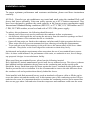
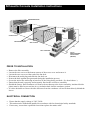
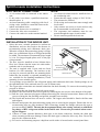
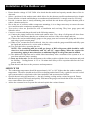
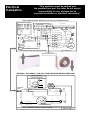
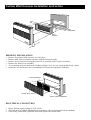
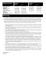
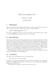
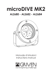
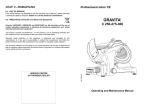
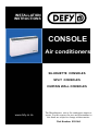
INSTALLATION
INSTRUCTIONS
CONSOLE
Air conditioners
SILHOUETTE CONSOLES
SPLIT CONSOLES
CURTAIN WALL CONSOLES
www.defy.co.za
The Manufacturer strives for continuous improvements. For this reason, the text and illustrations in
this book are subject to change without notice.
Part Number 059 044
Installation notes.
To ensure optimum performance and customer satisfaction, please read these instructions
carefully.
All Defy Console type air-conditioners are tested and rated using the standard Defy wall
sleeve and louvre assembly. Units can safely operate up to 43°C outdoor temperature. They
have been designed to produce the rated capacity at the lowest power consumption under
International Standard Rating conditions.(ISO5151) at 27°C DB, 19°C WB indoor and 35°
C DB, 24°C WB outdoor, at sea level and with a 230V 50Hz power supply.
To achieve this performance, the following should be noted:
• Smooth curved louvers are used to maximise the condenser airflow requirements.
• Air deflectors which guide the air leaving the unit away from the return air openings are fitted
onto the condenser coil to minimise hot air re-circulation.
• Open cell foam strips are fitted to the condenser end plates and fit tight up against the louvre.
These strips effectively prevent unwanted air from entering or leaving the compartments.
• To prevent rain water from entering via the wall sleeve, the bottom panel of the sleeve slants
outwards . Weep holes at the lower edge allow rainwater to drain away freely.
Architectural and aesthetic requirements often necessitate the use of non standard louver assemblies. As these could influence the performance of the units, we undertake to test, free of charge,
any proposed designs in our calorimeter facility
When specifying non standard louvers, please bear the following in mind:
Defy Appliances Limited, manufactures special wall sleeves without louvers. This sleeve is shorter
than standard and thus minimises the gap between the condensing unit and the outside grille
Should the factory fitted foam strips not locate against the louver, insulated divider plates must be
fitted to prevent hot air re-circulation. It is also recommended to remove the side deflectors from
the condenser coil and reposition them directly behind the louvre.
Units installed with flush mounted louvers, need an insulated wall spacer collar to fill the gap between the indoor unit and the outside wall. In this instance part of the condensing section will protrude into the room. It is important therefore to insulate the condensing section and to ensure that
there are no gaps where heat and noise from the compressor and condenser could enter the room.
Silhouette Console Installation instructions
MOUNTING HOLES
900
550
720
390
735
220
400
CONSOLE UNIT
405
310
335
MOUNTING HOLES
WALL SLEEVE
745
100
WALL APERTURE
100mm.
ABOVE FINISHED
FLOOR LEVEL
(INDOOR)
PRIOR TO INSTALLATION
•
•
•
•
•
•
•
•
Remove the filter assembly.
Loosen the two screws at the bottom corners of the access cover and remove it.
Loosen the two screws at either end of the fan deck.
Disconnect the multi-plug and slide the fan deck out.
Protect the deck against dust generated during the installation process.
Secure the unit to the wall using at least four of the fixing holes provided. ( See sketch above )
Ensure that the unit is properly and accurately fitted to the wall sleeve assembly.
Should the factory fitted condenser coil foam seals not butt up to the louver assembly, insulated divider
plates must be fitted to prevent hot air re-circulation back into the condenser section.
• It is also advisable to remove the side deflectors from the condenser coil and fit them directly behind the
louvre.
ELECTRICAL CONNECTION
•
•
•
Ensure that the supply voltage is 230V 50 Hz
This unit must be earthed and installed in accordance with local municipal safety standards.
If necessary, ensure that a qualified electrician replaces the mains cable.
Split Console installation instructions
ELECTRICAL CONNECTIONS
NOTE.
•
•
A 16A mains cable is connected to the indoor
unit.
• If this cable is too short, a qualified electrician
should replace it.
• An interconnecting cable complying with local
wiring codes, should be connected between the
indoor and outdoor units.
1. Connect the brown wire to terminal 1
2. Connect the blue wire to terminal 2
3. Connect the earth wire to the terminal marked
•
•
•
•
•
•
An electrical isolator must be installed close to
the condensing unit.
Ensure that the supply voltage is 230V 50 Hz.
The unit must be earthed.
Field wiring and connections must comply with
local codes.
Only connect one unit to a circuit and use only
the recommended circuit breaker size.
The evaporator and condenser must be connected through the same circuit breaker.
Please consult a qualified electrician.
INSTALLATION OF THE INDOOR UNIT.
•
•
•
•
•
Select the most suitable position for uniform air
distribution, and one that requires the shortest inFIXED BRACKETS
terconnecting tubing and condensate drain pipe.
WALL MOUNTED BRACKETS
When the required interconnecting piping is longer
than 9m. an additional 20g/m of refrigerant should
be added. The maximum recommended pipe length
is 16 m. For longer lengths please refer to the pipe
sizing manuals.
The unit must be installed at least 100mm above
floor level. Ensure that the return air outlet underFIXING SCREW
neath the unit is not obstructed.
SLIDING PLATE
MESH
The unit is supplied with 2 loose and two fixed
DIRECTION OF MOVEMENT
brackets for wall mounting. The brackets at the
MOUNTING HOLE
rear may be removed and there are mounting holes
behind the fan assembly or optional mounting feet
are available for free standing installations, if wall
mounting is not a suitable option.
Two openings are provided for the refrigerant piping and condensate drain tube. Both openings are on
the right hand side of the unit and cater for rear or bottom entry.
The copper tube connections are situated behind the fan deck assembly. To remove the assembly please
proceed as follows:(a) Disconnect the unit from the electrical power supply.
(b) Remove the filter and the front access panel by removing the two screws at the bottom of the panel.
(c) Pull the 4 pin connector plug apart without unscrewing the electrical connections. Remove the four
screws securing the fan assembly and pull the assembly out carefully.
(d) The liquid and suction lines will now be visible. The copper tubes should be fitted with flare nuts
and stoppers.
(e) Measure and prepare the interconnecting piping prior to removing the stoppers. Ensure that the interconnecting pipes are fully insulated. After connecting, insulate the fittings with non drip tape to
prevent sweating. NOTE: The unit has been pumped down after testing and only a small holding charge of R22 refrigerant will be in the indoor unit. Please take precautions when removing the stoppers.
(f) Connect a 19mm (internal diameter) drain pipe to the drain connection. Insulate the drain pipe
where sweating could cause damage. Ensure the drain pipe is slanted to allow easy flow. Do not use
traps for the condensate drain.
(g) For service and warranty purposes a duplicate serial sticker is located on the control panel door.
Installation of the Outdoor unit
•
•
•
•
•
•
Ensure that the voltage is 230V 50Hz. Also check that the model and capacity matches those of the indoor unit.
Select a position for the outdoor unit which allows for the shortest possible unobstructed pipe length.
Ensure that the air intake and discharge are unobstructed and that there is enough room for servicing.
Provide a concrete base or sturdy mounting plate and bolt the unit down using anti-vibration pads to
reduce vibration and noise.
Due to the use of resilient, rubber compressor mountings, it is no longer necessary to remove the outer
cover and loosen the compressor mounting nuts.
Two service valves are provided for ease of installation and servicing. They have gauge ports and
Schrader valves.
Connect, evacuate and charge the unit in the following manner:(a) Connect the piping between the indoor and outdoor units. Use a drop of refrigerant oil when forming the flares and ensure that they are without burrs and are of the correct shape and size.
(b) Connect the suction and discharge gauges to the gauge ports and evacuate the piping and the indoor
unit using a good vacuum pump.
(c) When a low vacuum has been achieved, close the valves and the gauge manifolds and fully open
the liquid and suction service valves with an allan key.
(d) Test for leaks before operating the unit.
NOTE:- The condensing unit has a full gas charge of R22 refrigerant which should be sufficient for a back-to-back installation with 1/4” and 1/2” copper tubing. When the required interconnecting piping is more than 9m, an additional 20g/m of refrigerant must be added.
(e) The additional refrigerant can be added either immediately after evacuation of the system or in vapour form when the unit is running.
(f) Start up of the unit: Set the thermostat to the coldest position with the fan on maximum and push
the Heating / Cooling button. A 2.5 to 3.0 minute time delay will be experienced before the compressor starts.
(g) Run the unit and observe the pressures and temperatures.
SERVICE TIP
•
•
•
The condensing temperature should be approximately 16°C to 18°C higher than the outdoor ambient
temperature. The above should not be used as a charging method and is only a guide for new air-cooled
split systems and air-cooled units with clean condensers and an unrestricted airflow.
Operate the unit using all functions i.e.; fan only, heating, cooling and at various fan speeds. Ensure
that the unit operates efficiently and quietly. Disconnect the gauges and check that all the screws that
were removed have been replaced.
Advise the customer how to operate the unit and explain the various features.
“This appliance must be earthed and
the manufacturer and the seller do not accept
responsibility for any damage due to
incorrect installation or electrical connection.”
Electrical
Installation
INTER CONNECTING WIRING DIAGRAM FOR SPLIT EVAP AND CONDENSER SECTION
INTERCONNECTING
SPLIT EVAP. AND COND. WIRING DIAGRAM
1
BLACK
BLACK
BLUE
1
N1
N1
N2
N2
N2
N2
H
H
HH
WHITE / BROWN
2
BROWN
GREEN / YELLOW
CONNECTING
CABLE
WIRING TERM.
BLOCK
BLUE
N1
N1
GREY
2
RED
F
GREEN
GREEN/
YELLOW
YELLOW
F
HI
HI
MED
MED
LO
LO
BLACK
BLACK
BLUE
BLUE
WHITE
CAP
EVAP.
FAN
CAP.
BROWN
GREEN / YELLOWCOND.
SPLIT
EE
GR
COND.
CONNECT.
SPLIT
CABLE
CONDENSER
BLUE
E
GREEN / YELLOW
GREEN / YELLOW
BROWN
GREEN / YELLOW SPLIT
BLUE
W
LO
EL
/Y
BLUE
BLUE
N
BLUE
E
E
GREEN / YELLOW
PURPLE PURPLE
L
GREEN / YELLOW
WHITE / BROWN
E
BROWN
HEATER
HEATER
HEATER
WHITE / BROWN
WHITE /
BLUE
GREEN / YELLOW
WHITEWHITE
/
BLUEBLUE
HEATER
BLUE / BLACK
WHITE / BROWN
BROWN
BLUE
BLUE
C4 L3 H6
BROWN
BROWN
4
EARTH
WHITE (N)
3
T / STAT
WHITE (N)
2
INT. FAN
WHITE / BLUE
1
BROWN
GREEN / YELLOW
MAINS
CABLE
N
L
EXT. FAN COMP. NEUTRAL LIVE HEAT
N
WHITE/ /BROWN
BROWN
WHITE
SELECTOR SWITCH
GREEN / YELLOW
EARTH
ELECTRONIC MODULE
GREEN / YELLOW
I-FAN MED
BLUE
L
ELECTRO MECHANICAL CONTROLS
RED I-FAN H LOW
GREY
X-FAN
BROWN
I-FAN HI
MAINS
CABLE
BLACK
NEUTRAL
LIVE
HEAT
PURPLE
BROWN
WHITE / BROWN
BLUE / BLACK
WHITE / BLUE
BLUE
COMP
WIRING FOR ELECTRONIC CONTROL
EVAP.
EVAP
FAN
FAN
MOTOR
MOTOR
RED
BROWN
BLUE
SILHOUETTE SPLIT EVAPORATOR / WIRING DIAGRAM
ELECTRO MECHANICAL SPLIT EVAPORATOR WIRING DIAGRAM
PART NUMBER 059169
MED FAN SPEED LEAD
USE ON ELECTRONIC MODULE ONLY
WARNING: DISCONNECT THE UNIT FROM THE MAINS BEFORE SERVICING
WIRING FOR EXTERNAL
OVERLOAD COMPRESSOR
GREEN / YELLOW
BLACK
O/L
PURPLE
C
COND.
FAN
MOTOR
RED
S
BLUE
1
BLUE
WHITE
GREEN / YELLOW
PINK
FAN
CAP.
BROWN
PURPLE
BROWN
2
WHITE
YELLOW
CONNECTING
CABLE
BLUE
BLUE
R
C
R
RED
GREEN / YELLOW
S
GREEN / YELLOW
MUSTARD
COMP.
CAP.
COMPRESSOR
SPLIT CONDENSER ELECTRICAL WIRING DIAGRAM
PART No. 058407
Curtain Wall Console Installation Instruction
95
410
815
405
810
WALL
APERTURE
WALL
SLEEVE
60
PRIOR TO INSTALLATION
•
•
•
•
•
•
Remove Front Inlet Grille and store in a safe place.
Remove both Filter Assemblies and store with the front inlet grille.
Remove the two screws securing the Front Cover assembly to the Chassis Assembly.
Remove the Front Cover assembly
Two mounting holes, located on the Condenser Back Cover, are now exposed and clearly visible.
Isolate the area and be sure not to contaminate the Electrical components with dust.
FILTER ASSEMBLY
FRONT INLET GRILLE
FRONT COVER ASSEMBLY
ELECTRICAL CONNECTION
•
•
•
Ensure that the supply voltage is 230V 50 Hz
This unit must be earthed and installed in accordance with local municipal safety standards.
If necessary, ensure that a qualified electrician replaces the mains cable.
Defy branch
Sales
Phone
JOHANNESBURG
PRETORIA
BLOEMFONTEIN
DURBAN
CAPE TOWN
PORT ELIZABETH
NAMIBIA
BOTSWANA
SWAZILAND ( AGENT)
011 621 0200
——————
051 400 3900
031 460 9649
021 551 8314
041 401 6400
09264 61 216162
09267 306476
09268 518 6527
Parts
Fax
Phone
Fax
011 621 0399
——————
051 400 3950
031 460 9631
021 551 8228
041 401 6501
09264 61 216134
09267 359705
09268 518 4318
011 621 0200
012 377 0061
051 400 3900
031 460 9712
021 551 8314
041 401 6400
—————
—————
—————
011 621 0396
012 377 0398
051 400 3951
031 460 9988
021 551 8342
041 401 6499
—————
—————
—————
Warranty
Defy Appliances (“the Company”) warrants to the purchaser to whom the product was sold by the dealer appointed by
the company to distribute its products (“authorized dealer”) and in respect of which no prior sale of the product was
made (“original purchaser”) that the Defy Air conditioning unit (“product”) sold with this certificate is free of defects
in material of workmanship under normal use and service for a period of 2 years from the date of purchase thereof.
The warranty period of 2 years for console air conditioners is subject to a signed service and maintenance agreement
between a Defy authorized contractor and the end user for the full warranty period. Without a service/maintenance
agreement the warranty period of 1 year applies. The warranty is subject to the following conditions:
1. This warranty shall apply to the product, provided the product is still owned by the original purchaser and provided that it was purchased in and is retained for use in the Republic of South Africa, Swaziland, Lesotho, Botswana and Namibia.
2. The Company undertakes to, within 2 years from date of the invoice issued to the original purchaser, through an
authorized dealer appointed by its regional office in its discretion, replace or repair, free of charge, any parts of
the product, which may be faulty.
3. It is a condition of this warranty that the Company shall not be responsible for any transportation, labour, material
or any other costs not specified in the clauses contained herein.
4. The product shall be serviced regularly by an authorized dealer (which intervals shall not exceed 6 months) and
failure to comply with this condition shall render the warrant null and void.
5. The Company shall not be responsible for damage to the product resulting from incorrect voltage or fault in the
electrical power supply system, general misuse or abuse of the product, failure to use the product for the purpose
for which it was designed, fire, flood, war, civil disturbances, strikes, lockouts, acts of God, acts of Government,
or quasi-Government, or any other cause beyond the reasonable control of the Company.
6. The Company shall not accept any responsibility or liability (whether in contract and / or delict and / or otherwise), for any loss suffered by or damage of any kind caused to the original purchase or any other person by or
due to failure of operation or malfunction of the product or for consequential damage of whatsoever nature,
whether such loss, damage or consequential damage was suffered by the original purchaser or any other person.
7. Should the product be worked on by anyone other than a Regional Office service representative or authorised service dealer or be found to contain any component parts or accessories other than product component parts of accessories, this warranty will become null and void.
8. The defacement or removal of the nameplate and or serial number from the product will render the warranty null
and void.
9. The warranty does not apply to filters, external cables and plugs, nor to any parts where the length of life depends
on the amount of use and care given. Transport and handling damages are not covered by this warranty.
10. Save as set out in this warranty, no terms, conditions, provisions, representations or statements (whether express
or implied) shall be of any force or effect whether made prior to, on, or subsequent to the date of original purchase, unless the same shall have been confirmed in writing by the Company.
11. The product has been designed for normal use. If the product is used for abnormal applications i.e. operation outside its design conditions, operation with restrictive louvers, which have not been approved by Defy Appliances
Ltd., extreme high or low temperatures, dusty and / or highly polluted areas or any other similar or related purpose, the warranty shall be rendered null and void.
Defy Appliances Ltd
PO Box 12004
Jacobs 4026