1
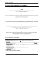
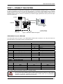
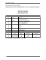
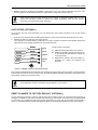
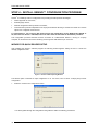
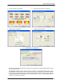
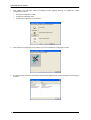
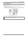
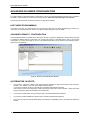
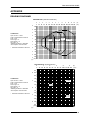
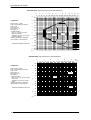
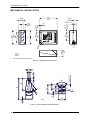
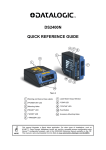
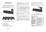
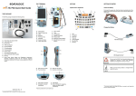
DS2100N
QUICK REFERENCE GUIDE
4
2
1
5
6
3
7
11
10
9
Figure A
NOTE
8
1
Warning and Device Class Labels
7
Laser Beam Output Window
2
"POWER ON" LED
8
"COM" LED
3
Mounting Holes
9
"STATUS" LED
4
"READY" LED
10 Push Button
5
"GOOD" LED
11 Accessory Mounting Holes
6
"TRIGGER" LED
This manual illustrates a Stand Alone application. For other types of installations, such as
ID-NET™, Pass-Through, Multiplexer Layout, etc. and for a complete scanner configuration using
Genius™ configuration program, refer to the DS2100N Reference Manual available on the CD.
This manual is also downloadable from the Web at www.automation.datalogic.com/ds2100n.
DS2100N QUICK GUIDE
UPDATES AND LANGUAGE AVAILABILITY
UK/US
The latest drivers and documentation updates for this product are available on Internet.
Log on to: www.automation.datalogic.com
I
Su Internet sono disponibili le versioni aggiornate di driver e documentazione di questo prodotto. Questo manuale
è disponibile anche nella versione italiana.
Collegarsi a: www.automation.datalogic.com
F
Les versions mises à jour de drivers et documentation de ce produit sont disponibles sur Internet. Ce manuel est
aussi disponible en version française.
Cliquez sur : www.automation.datalogic.com
D
Im Internet finden Sie die aktuellsten Versionen der Treiber und Dokumentation von diesem Produkt. Die
deutschsprachige Version dieses Handbuches ist auch verfügbar.
Adresse : www.automation.datalogic.com
E
En Internet están disponibles las versiones actualizadas de los drivers y documentación de este producto.
También está disponible la versión en español de este manual.
Dirección Internet : www.automation.datalogic.com
SERVICES AND SUPPORT
Datalogic provides several services as well as technical support through its website. Log on to
www.automation.datalogic.com and click on the links indicated for further information including:
•
PRODUCTS
Search through the links to arrive at your product page where you can download specific Manuals and
Software & Utilities including:
- Genius™ a utility program, which allows device configuration using a PC. It provides RS232 interface
configuration.
•
SERVICES & SUPPORT
- Datalogic Services - Warranty Extensions and Maintenance Agreements
- Authorised Repair Centres
•
CONTACT US
E-mail form and listing of Datalogic Subsidiaries
2
DS2100N QUICK GUIDE
STEP 1 – CONNECT THE SYSTEM
To connect the system in a Stand Alone configuration, you need the hardware indicated in Figure 1. In this layout
the data is transmitted to the Host on the main serial interface. In Local Echo communication mode, the RS232
auxiliary interface can be used to transmit data independently from the main interface selection. When On-Line
Operating mode is used, the scanner is activated by an External Trigger (photoelectric sensor) when the object
enters its reading zone.
PG 6000
MAIN
DS2100N
CBX100/500
Host
P.S.*
I/O, AUX
* Presence Sensor
(for On-Line mode)
Figure 1 – DS2100N in Stand Alone Layout
CBX100/500 Pinout for DS2100N
The table below gives the pinout of the CBX100/500 terminal block connectors. Use this pinout when the
DS2100N reader is connected by means of the CBX100/500:
Vdc
GND
Earth
+V
I1A
I1B
-V
+V
I2A
I2B
-V
Shield
CBX100/500 Terminal Block Connectors
Power
Outputs
Power Supply Input Voltage +
+V
Power Source - Outputs
Power Supply Input Voltage -V
Power Reference - Outputs
Protection Earth Ground
O1+
Output 1 +
O1Output 1 Inputs
O2+
Output 2 +
Power Source – External Trigger
O2Output 2 Auxiliary Interface
External Trigger A (polarity insensitive)
External Trigger B (polarity insensitive)
TX
Auxiliary Interface TX
Power Reference – External Trigger
RX
Auxiliary Interface RX
Power Source – Inputs
SGND
Auxiliary Interface Reference
ID-NET™
Input 2 A (polarity insensitive)
Input 2 B (polarity insensitive)
REF
Network Reference
Power Reference – Inputs
ID+
ID-NET™ network +
Shield
IDID-NET™ network Network Cable Shield
Main Interface
RS232
RS485 Full-Duplex
RS485 Half-Duplex
TX
TX+
RTX+
RTS
TXRTX*RX+
RX
*RXCTS
SGND
SGND
SGND
* Do not leave floating, see Reference Manual for connection details.
CAUTION
Do not connect GND, SGND and REF to different (external) ground references. GND, SGND
and REF are internally connected through filtering circuitry which can be permanently
damaged if subjected to voltage drops over 0.8 Vdc.
3
DS2100N QUICK GUIDE
25-pin Connector Pinout for DS2100N
The table below gives the pinout of the 25-pin male D-sub connector for connection to the power supply and
input/output signals. Use this pinout when the DS2100N reader is connected by means of the 25-pin connector:
1
13
14
25
Figure 2 - 25-pin Male D-sub Connector
25-pin D-sub male connector pinout
Pin
13, 9
25, 7
1
18
19
6
10
8
22
11
12
20
21
23
24
14, 15, 16, 17
Name
Function
Vdc
GND
CHASSIS
I1A
I1B
I2A
I2B
O1+
O1O2+
O2RX
TX
ID+
IDNC
Power supply input voltage +
Power supply input voltage Cable shield connected to chassis
External Trigger A (polarity insensitive)
External Trigger B (polarity insensitive)
Input 2 A (polarity insensitive)
Input 2 B (polarity insensitive)
Output 1 +
Output 1 Output 2 +
Output 2 Auxiliary RS232 RX
Auxiliary RS232 TX
ID-NET™ network +
ID-NET™ network Not Connected
RS485
RS232
Full-Duplex
TX
TX+
*RX+
RX
RTS
TX*RXCTS
Pin
Name
2
3
4
5
MAIN INTERFACE
(SW SELECTABLE)
* Do not leave floating, see Reference Manual for connection details.
4
RS485
Half-Duplex
RTX+
RTX-
DS2100N QUICK GUIDE
STEP 2 – MOUNT AND POSITION THE SCANNER
1.
To mount the DS2100N, use the mounting bracket to obtain the most suitable position for the reader as
shown in the figures below.
Skew
Pitch
Tilt
Skew
2.
Figure 3 - Positioning with Mounting Bracket
When mounting the DS2100N take into consideration these three ideal label position angles:, Skew 10° to 30°,
Tilt 0° and Pitch 0°.
P
T
S
Assure at least 10°
Minimize
Minimize
Figure 4 –, Skew, Tilt and Pitch Angles
3.
Refer to the Reading Diagrams in the Appendix of this Quick Reference Guide to decide the distance your
scanner should be positioned at.
5
DS2100N QUICK GUIDE
STEP 3 – X-PRESS™ CONFIGURATION
X-PRESS™ is the intuitive Human Machine Interface designed to improve ease of installation and maintenance.
Status and diagnostic information are clearly presented by means of the five colored LEDs, whereas the single
push button gives immediate access to the following relevant functions:
•
Test Mode with bar graph visualization to check static reading
performance
•
AutoLearn to self-detect and auto-configure for reading unknown
barcodes (by type and length)
•
AutoSetup to self-optimize and auto-configure reading performance in
demanding applications
NOTE
If using the OM2000N accessory, when entering the X-PRESS™ interface, the Oscillating Mirror
remains in the default fixed position (-15°) in order to make barcode reading easier while
performing the X-PRESS™ functions.
The colors and meaning of the five LEDs are illustrated in the following table:
READY (green)
GOOD (green)
TRIGGER (yellow)
COM (yellow)
STATUS (red)
This LED indicates the device is ready to operate.
This LED confirms successful reading.
This LED indicates the status of the reading phase.
This LED indicates active communication on main serial port.
This LED indicates a NO READ result.
During the reader startup (reset or restart phase), all the LEDs blink for one second.
On the back of the reader near the cable, the “POWER ON” LED indicates the laser scanner is correctly powered.
AUTO LEARN
If you are configuring your scanner using X-PRESS™, you must start with the Auto Learn procedure.
1.
Enter the Auto Learn function by holding the X-PRESS™ push button pressed until the LEARN LED is on.
2.
Release the button to enter the Auto Learn function.
Once entered, the reader starts a procedure to automatically detect and recognize barcodes (by type and
length), which are presented to it (*). The laser turns on and the LEARN LED blinks to indicate the ongoing
process.
READY
SETUP
LEARN
TEST
GOOD
TRIGGER
COM
STATUS
green
green
yellow
yellow
red
The procedure is as follows:
A) place the desired barcode on the scanline.
B) wait until the LEARN LED stays steady on
(indicating the reader has detected the
barcode).
C) repeat, if needed, the above two steps to
program up to 10 different barcodes (either
by length or by symbology). If more than one
barcode is detected, the Multi Label mode is
enabled (refer to the “2K/4K Family Software
Configuration Parameter Guide” Help file).
Figure 5 – X-PRESS™ Interface: Auto Learn Function
* In case of Programming Barcodes, refer to the “ID-NET™ Programming Barcodes And Setup Procedure” document in the
product CD.
6
DS2100N QUICK GUIDE
3.
Exit the process by pressing the X-PRESS™ push button once. The scanner will restart at the end of the
process, and then the detected barcodes are automatically configured in scanner memory.
NOTE
If the barcode cannot be read because of low contrast or excessive ambient light, you can
perform the AutoSetup function to optimize the optical parameters. Then you can perform
AutoLearn to recognize the barcode symbology.
AUTO SETUP (OPTIONAL)
At the end of the Auto Learn procedure, you can perform the Auto Setup procedure to set up the reading
parameters.
1.
Enter the Auto Setup function by holding the X-PRESS™ push button pressed until the SETUP LED is on.
2.
Release the button to enter the Auto Setup function.
Once entered, if a barcode label is positioned in front of the scanline, the scanner automatically performs the
optimal setup of the reading parameters for that specific barcode.
READY
SETUP
LEARN
TEST
GOOD
TRIGGER
COM
STATUS
green
green
yellow
yellow
red
The procedure is as follows:
A) place the desired barcode on the scanline.
B) enter the AutoSetup function (the laser turns
on and the SETUP LED blinks to indicate the
ongoing process)
C) wait until the SETUP LED stays steady on
(indicating the reader has detected the
barcode)
Figure 6 – X-PRESS™ Interface: Auto Setup Function
This procedure ends either when the barcode is successfully decoded or after a timeout of about 7 (seven) seconds.
The scanner will restart at the end of the process, and then the optimized reading parameters for that barcode are
automatically configured in scanner memory.
If your application has been configured using X-PRESS™, go to STEP 5.
NOTE
RESET SCANNER TO FACTORY DEFAULT (OPTIONAL)
If it ever becomes necessary to reset the scanner to the factory default values, you can perform this procedure by
holding the X-PRESS™ push button pressed while powering up the scanner. At the end of the procedure (about
5-6 seconds), the Configuration and Environmental parameters are reset and all LEDs blink simultaneously 3
times. If connected through a CBX500 with display module, the message "Default Set" is shown on the display.
7
DS2100N QUICK GUIDE
STEP 4 – INSTALL GENIUS™ CONFIGURATION PROGRAM
Genius™ is a Datalogic scanner configuration tool providing several important advantages:
•
Wizard approach for new users;
•
Multi-language version;
•
Defined configuration directly stored in the reader;
•
Communication protocol independent from the physical interface allowing to consider the reader as a remote
object to be configured and monitored.
To install Genius™, turn on the PC that will be used for the configuration, running Windows 98, 2000/NT or
XP, then insert the Genius™ CD-ROM, wait for the CD to autorun and follow the installation procedure.
This configuration procedure assumes scanner connection to a CBX100/500. Genius™, running on a laptop
computer, is connected to the scanner auxiliary port through the CBX100/500 9-pin connector.
WIZARD FOR QUICK READER SETUP
After installing the Genius™ software program the following window appears asking the user to choose the
desired configuration level.
Figure 7 - Genius™ Wizard Opening Window
The Wizard option is advised for rapid configuration or for new users, since it shows a step-by-step scanner
configuration.
1.
Select the Create a new configuration button.
You will be guided through the configuration being asked to define the following parameters:
8
DS2100N QUICK GUIDE
a.
Barcode selection and definition
b.
Operating mode selection and definition
c.
Digital Outputs configuration
d.
Hardware interface selection
e.
Output data format configuration
The On Line operating Mode requires the reader to be connected to an External Trigger/Presence Sensor
using I1A and I1B inputs.
The Automatic operating mode does not require connection to an external Presence Sensor. When
working in this mode the reader is continuously scanning, while the reading phase is activated each time a
barcode enters the reader reading zone. The reader stops reading after an N number of scans without a
code. Barcode characters are transmitted on the serial interface. In case of a failed reading phase no
message is sent to the host computer.
9
DS2100N QUICK GUIDE
2.
After defining the parameter values the following window appears allowing to complete the reader
configuration as follows:
•
Saving the configuration to disk;
•
Switching to Advanced mode;
•
Sending the configuration to the scanner.
3.
After sending the configuration to the scanner you have completed the configuration process.
4.
By clicking Finish, the System Information window will be displayed with specific information concerning the
scanner.
10
DS2100N QUICK GUIDE
STEP 5 – TEST MODE
Use a code suitable to your application to test the system. Alternatively, you can use the Datalogic Test Chart
(Interleaved 2/5 or Code 39).
1.
Enter the Test mode function by holding the X-PRESS™ push button pressed until the TEST LED is on.
2.
Release the button to enter the Test mode function.
Once entered, the Bar-Graph on the five LEDs is activated and if the scanner starts reading barcodes the
Bar-Graph shows the Good Read Rate. In case of no read condition, only the STATUS LED is on and blinks.
READY
SETUP
LEARN
TEST
GOOD
TRIGGER
COM
STATUS
green
green
yellow
yellow
red
Figure 8 – X-PRESS™ Interface: Test Mode Function
3.
To exit the Test Mode, press the X-PRESS™ push button once.
By default, the Test Mode exits automatically after two minutes.
NOTE
11
DS2100N QUICK GUIDE
ADVANCED SCANNER CONFIGURATION
For further details on advanced product configuration, refer to the complete Reference Manual on the installation
CD-ROM or downloadable from the web site through this link: www.automation.datalogic.com/ds2100n.
The following are alternative or advanced scanner configuration methods:
HOST MODE PROGRAMMING
The scanner can also be configured from a host computer using the Host Mode programming procedure, by
commands via the serial interface. See the Host Mode Programming file on the CD-ROM.
ADVANCED GENIUS™ CONFIGURATION
The ADVANCED selection available when starting the Genius™ program is addressed to expert users being able
to complete a detailed scanner configuration. By choosing this option it is possible either to start a new scanner
configuration or to open and modify an old one. The desired parameters can be defined in the following window,
similar to the MS Explorer:
Figure 9 - Genius™ Parameter Explorer Window
ALTERNATIVE LAYOUTS
•
The ID-NET™ network is a built-in high-speed interface dedicated for high-speed scanner interconnection.
ID-NET™ is in addition to the Main and Auxiliary serial interfaces.
If you need to install an ID-NET™ network refer to the DS2100N Reference Manual.
The scanner can also be configured by reading programming barcodes. See the ID-NET™ Setup Procedure
Using Programming Barcodes printable from the CD-ROM.
•
If you need to install a Pass-Through network refer to the DS2100N Reference Manual.
•
If you need to install a Multiplexer network refer to the DS2100N Reference Manual.
•
If you need to install an RS232 Master/Slave (for backward compatibility) refer to the DS2100N Reference
Manual.
12
DS2100N QUICK GUIDE
APPENDIX
READING DIAGRAMS
DS2100N-1200 (Standard Resolution)
0
0
5
4
CONDITIONS
3
Optic Version = Linear
Code = Interleaved 2/5 Code 39
PCS = 0.90
Pitch angle = 0°
Skew angle = 15°
Tilt angle = 0°
*Reading Conditions = Standard
*Scan Speed = 500 scans/sec
2
* Parameter selectable in Genius™
2
1
20
2
40
3
60
4
5
6
7
8
9
10
11
12
(in)
80 100 120 140 160 180 200 220 240 260 280 300 (mm)
120
100
80
60
40
1
20
0
0
1
20
0.20 mm
(8 mils)
0.30 mm
(12 mils)
0.35 mm
(14 mils)
≥ 0.50 mm
(20 mils)
40
60
3
80
4
100
5
(in)
120
(mm)
DS2100N-2200 (High Resolution)
0
0
1
10
20
2
30
40
50
3
60
70
4
80
5
90 100 110 120 130
(in)
(mm)
60
2
50
40
CONDITIONS
Optic Version = Linear
Code = Interleaved 2/5 Code 39
PCS = 0.90
Pitch angle = 0°
Skew angle = 15°
Tilt angle = 0°
*Reading Conditions = Standard
*Scan Speed = 500 scans/sec
* Parameter selectable in Genius™
30
≥ 0.30 mm
(12 mils)
1
20
10
0
0.15 mm
(6 mils)
0
10
20
1
30
0.20 mm
(8 mils)
40
2
(in)
50
60
(mm)
13
DS2100N QUICK GUIDE
DS2100N-1204 High Performance (Standard Resolution)
0
1
0
5
Optic Version = Linear
Code = Interleaved 2/5 Code 39
PCS = 0.90
Pitch angle = 0°
Skew angle = 15°
Tilt angle = 0°
*Code Resolution:
High - for 0.30 mm (12 mils)
codes and smaller
Standard - for 0.50 mm (20 mils)
codes and greater
*Reading Conditions = Standard
*Scan Speed = 1000 scans/sec
2
40
3
60
4
5
6
7
8
9
10
11
(in)
12
80 100 120 140 160 180 200 220 240 260 280 300 (mm
120
100
4
CONDITIONS
20
80
3
60
2
40
1
20
0
0
1
20
0.15 mm
(6 mils)
0.30 mm
(12 mils)
0.20 mm
(8 mils)
≥ 0.50 mm
(20 mils)
40
2
60
* Parameter selectable in Genius™
3
80
4
100
5
(in)
120
(mm)
DS2100N-2204 High Performance (High Resolution)
0
0
1
10
20
2
30
40
50
3
60
70
4
80
90
5
100 110 120 130
60
CONDITIONS
Optic Version = Linear
Code = Interleaved 2/5 Code 39
PCS = 0.90
Pitch angle = 0°
Skew angle = 15°
Tilt angle = 0°
*Code Resolution:
High - for 0.15 mm (6 mils) codes
and smaller
Standard - for 0.20 mm (8 mils)
codes
*Reading Conditions = Standard
*Scan Speed = 1000 scans/sec
2
50
40
30
20
10
0
0.12 m m
(5 mils)
0
10
20
1
30
* Parameter selectable in Genius™
40
2
(in)
14
≥ 0.20 m m
(8 mils)
1
50
60
(m m )
0.15 m m
(6 mils)
(in)
(m m )
DS2100N QUICK GUIDE
READING PERFORMANCE
Version
1XX0
1XX4
2XX0
2XX4
Reading Distance
Max Code Resolution
mm (mils)
0.20 (8)
0.20 (8)
0.15 (6)
0.12 (5)
40 mm (1.6 in) - 300 mm (11.8 in) on 0.50 mm (20 mils) codes
50 mm (1.8 in) - 310 mm (11.8 in) on 0.50 mm (20 mils) codes
30 mm (1.2 in) - 90 mm (3.5 in) on 0.30 mm (12 mils) codes
45 mm (1.8 in) - 100 mm (3.9 in) on 0.20 mm (8 mils) codes
Speed
scans/s
500 to 800
800 to 1000
500 to 800
800 to 1000
TECHNICAL FEATURES
ELECTRICAL FEATURES
Power Supply
Consumption
Main Serial Interfaces
Baud Rate
Auxiliary Interface
Baud Rate
ID-NET™ Interface
Baud Rate
Inputs
Input 1 (External Trigger), Input 2
Voltage
Current Consumption
Minimum Pulse Duration
Outputs
Output 1, Output 2
VCE
Collector Current
VCE Saturation
Power Dissipation
DS2100-XXX0
DS2100-XXX4
10 to 30 Vdc
0.3 to 0.1 A; 3 W
0.5 to 0.17 A; 5 W
Programmable:
RS232, RS485 FD and HD
1200 to 115200
RS232
1200 to 115200
RS485 Half Duplex
Up to 1Mbaud
Optocoupled, polarity insensitive
10 to 30 Vdc
12 mA max.
5 ms
Optocoupled
30 Vdc max.
40 mA continuous max.; 130 mA pulsed max.
1V at 10 mA max.
80 mW max. at 45 °C (ambient temperature)
OPTICAL FEATURES
Light Source
Wavelength
Safety Class
READING FEATURES
Scan Rate (software programmable)
Aperture Angle
Maximum Reading Distance
Maximum Resolution
Semiconductor laser diode
In the range 630 to 680 nm
Class 2 – EN 60825-1; CDRH
500 to 800 scans/sec
800 to 1000 scans/sec
50°
See reading diagrams
ENVIRONMENTAL FEATURES
Operating Temperature c
Storage Temperature
Humidity max.
Vibration Resistance
EN 60068-2-6
Bump Resistance
EN 60068-2-29
Shock Resistance
EN 60068-2-27
Protection Class
0° to +45 °C (+32° to +113 °F)
-20° to +70 °C (-4° to +158 °F)
90% non condensing
14 mm @ 2 to 10 Hz; 1.5 mm @ 13 to 55 Hz;
2 g @ 70 to 200 Hz; 2 hours on each axis
30 g; 6 ms;
5000 shocks on each axis
30 g; 11 ms;
3 shocks on each axis
IP65
PHYSICAL FEATURES
Dimensions
Weight
68 x 84 x 34 mm (2.68 x 3.31 x 1.34 in)
330 g (11.6 oz)
USER INTERFACE
LED Indicators
Multi-function Key
Ready, Good, Trigger, Com, Status, Power On
X-PRESS™ button
c If the reader is used in high temperature environments (over 40 °C), use of the Beam Shutter is advised (see the Genius™
configuration program) and/or a thermally conductive support (such as the metal bracket provided).
15
DS2100N QUICK GUIDE
MECHANICAL INSTALLATION
84
3.31
23.3*
0.92
4
0.16
10.3
0.41
10.3
0.41
14
0.55
14.7
0.58
M 4 n° 4
DS2100N
GOOD
40
1.57
68
2.68
46
1.81
40
1.57
READY
SETUP
TRIGGER
LEARN
COM
TEST
STATUS
X PRESS
32.7
1.29
INTERFACE
mm
inch
*
The quote refers to the scan line
Figure 10 – DS2100N Overall Dimensions
9
2.5
mm
Figure 11 – Mounting Bracket Overall Dimensions
16
4.2 n° 2
4. 2
2.5
17.5
30
73
40
20°
13.8
R
42
90°
1 x 45° n° 2
7.8
4.2
23
DS2100N QUICK GUIDE
PATENTS
This product is covered by one or more of the following patents:
U.S. patent: 5,992,740
European patent: 789,315 B1
COMPLIANCE
LASER SAFETY
The scanner is classified as a Class 2 laser product
according to EN 60825-1 regulations and as a Class II
laser product according to CDRH regulations.
This product conforms to the
applicable requirements
of 21CFR1040 at the
date of manufacture
Disconnect the power supply when opening the device
during maintenance or installation to avoid exposure to
hazardous laser light.
There is a safety device, which allows the laser to be
switched on only if the motor is rotating above the
threshold for its correct scanning speed.
The laser beam can be switched off through a software
command (see also the Genius Help On Line).
LASER LIGHT
DO NOT STARE INTO BEAM
CLASS 2 LASER PRODUCT
The laser diode used in this device is classified as a
class 3B laser product according to EN 60825-1
regulations and as a Class IIIb laser product according
to CDRH regulations.
Any violation of the optic parts in particular can cause
radiation up to the maximum level of the laser diode
(35 mW at 630 to 680 nm).
MAX. OUTPUT RADIATION 1 mW
EMITTED WAVE LENGTH 630~680 nm
TO EN 60825-1:2001
CAUTION-CLASS 3B LASER LIGHT
WHEN OPEN AVOID EXPOSURE TO BEAM
Pat. US5992740, EP0789315B1
DATALOGIC AUTOMATION Srl
Via S. Vitalino, 13 – 40012 Calderara di Reno
MADE IN ITALY-www.datalogic.com
AVOID EXPOSURE LASER LIGHT
IS EMITTED FROM THIS APERTURE
Figure 12 - Warning and Device Class Labels
POWER SUPPLY
This product is intended to be installed by Qualified Personnel only.
This accessory device is intended to be supplied by a UL Listed or CSA Certified Power Unit with «Class 2» or
LPS power source, which supplies power directly to the scanner via the 25-pin connector.
CE COMPLIANCE
Warning: This is a Class A product. In a domestic environment this product may cause radio interference in
which case the user may be required to take adequate measures.
17
DECLARATION OF CONFORMITY
07
Datalogic Automation S.r.l.
Via S. Vitalino 13
40012 - Lippo di Calderara
Bologna - Italy
dichiara che
declares that the
déclare que le
bescheinigt, daß das Gerät
declare que el
e tutti i suoi modelli
and all its models
et tous ses modèles
und seine Modelle
y todos sus modelos
DS2100N Laser Scanner;
sono conformi alle Direttive del Consiglio Europeo sottoelencate:
are in conformity with the requirements of the European Council Directives listed below:
sont conformes aux spécifications des Directives de l'Union Européenne ci-dessous:
der nachstehend angeführten Direktiven des Europäischen Rats:
cumple con los requisitos de las Directivas del Consejo Europeo, según la lista siguiente:
89/336/EEC EMC Directive
e
and
et
und
y
92/31/EEC, 93/68/EEC
emendamenti successivi
further amendments
ses successifs amendements
späteren Abänderungen
succesivas enmiendas
Basate sulle legislazioni degli Stati membri in relazione alla compatibilità elettromagnetica ed alla sicurezza dei prodotti.
On the approximation of the laws of Member States relating to electromagnetic compatibility and product safety.
Basée sur la législation des Etats membres relative à la compatibilité électromagnétique et à la sécurité des produits.
Über die Annäherung der Gesetze der Mitgliedsstaaten in bezug auf elektromagnetische Verträglichkeit und Produktsicherheit
entsprechen.
Basado en la aproximación de las leyes de los Países Miembros respecto a la compatibilidad electromagnética y las Medidas
de seguridad relativas al producto.
Questa dichiarazione è basata sulla conformità dei prodotti alle norme seguenti:
This declaration is based upon compliance of the products to the following standards:
Cette déclaration repose sur la conformité des produits aux normes suivantes:
Diese Erklärung basiert darauf, daß das Produkt den folgenden Normen entspricht:
Esta declaración se basa en el cumplimiento de los productos con las siguientes normas:
EN 55022 (Class A ITE), August 1994:
Amendment A1 (Class A ITE), October 2000:
LIMITS AND METHODS OF MEASUREMENTS OF RADIO DISTURBANCE
EN 61000-6-2, October 2001:
ELECTROMAGNETIC COMPATIBILITY (EMC)
PART 6-2: GENERIC STANDARDS - IMMUNITY FOR INDUSTRIAL
CHARACTERISTICS OF INFORMATION TECHNOLOGY EQUIPMENT
ENVIRONMENTS
Lippo di Calderara, April 2nd, 2007
Lorenzo Girotti
Product & Process Quality Manager
821001293 (Rev. C)