1
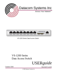
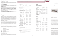
DATACOM
®
DATACOMsystems Family of Products
SYSTEMS INC
CAUTION: Changes or modifications to this unit not expressly approved by
the party responsible for compliance could void the user’s authority to operate
the equipment.
PORTS
TOPOLOGY
1X8SP-OM (S) 8 100FX, OC3, OC12, Gigabit Dual SC
1X8SY-OM (S) 8 100FX, OC3, OC12, Gigabit Dual SC
MODEL
™
MODEL
PORTS
TOPOLOGY
2x8
ATM, OC3-OC12
Dual SC
2X16FD-SY
2x16
MX8100E/Tsl
2x8
MX16100E/Tsl 2x16
Customer Service
TOPOLOGY
This Quick Installation Guide was written to help you get to know your new
10/100-AT quickly and easily. We would welcome any comments or suggestions you may have regarding this Quick Installation Guide. Please send your
remarks and recommendations via mail, telephone, facsimile, or Internet Email.
10/100 BaseT
10/100 BaseT or Token
10/100 BaseT or Token
MODEL
RJ45
RJ45
RJ45
Datacom Customer Service personnel are available from 8 AM to 5:30 PM
Eastern time, weekdays. Customer Service is available via telephone, facsimile,
and Internet E-mail. Outside of support hours, please leave a voice message and
our Customer Service Staff will return your call as soon as possible.
Mail:
Datacom Systems, Inc.
Customer Service
9 Adler Drive
East Syracuse, NY 13057-1290
Tel:
(315) 463-9541
FAX: (315) 463-9557
E-mail: [email protected]
PORTS
TOPOLOGY
CONNECTIVITY
4
4X8
4X8
4X16
Gigabit
Gigabit
Gigabit
Gigabit
Dual SC
Dual SC
Dual SC
Dual SC
MODEL
PORTS
TOPOLOGY
CONNECTIVITY
1x8
2x8
Gigabit
Gigabit
Dual SC
Dual SC
PORTS
TOPOLOGY
CONNECTIVITY
1x8
2x4
2x8
Gigabit
Gigabit
Gigabit
Dual SC
Dual SC
Dual SC
PORTS
TOPOLOGY
CONNECTIVITY
2x8
Gigabit
Dual SC
1X8SY-SX (LX)
2X8SY-SX (LX)
1X8SP-SX (LX)
2X4SY-SX (LX)
2X8SY-SX (LX)
2X8SP4-SX (LX)
CONNECTIVITY
100FX, OC3, OC12, Gigabit Dual SC
100FX, OC3, OC12, Gigabit Dual SC
OC3, OC12, Gigabit
Dual SC
PORTS
TOPOLOGY
CONNECTIVITY
2x8
Gigabit
Dual SC
MODEL
PORTS
TOPOLOGY
4SY-SX+4C
4
Gigabit
MODEL
DS3AT1 (4) (8)
DS3-AT
DS3/E3-PT
E3-AT
T1/E1-PT
CONNECTIVITY
Dual SC & LC
PORTS
TOPOLOGY
1 (4) (8)
1
1
1
1
DS3
DS3
DS3/E3
E3
T1/E1
CONNECTIVITY
BNC
BNC
BNC
BNC
RJ48
VERSAlink
™
MODEL
PORTS
TOPOLOGY
CONNECTIVITY
1X4SY-SX+2C
1X8SY-SX+2C
2X4SY-SX+2C
2X8SY-SX+2C
1X4
1X8
2X4
2X8
Gigabit
Gigabit
Gigabit
Gigabit
Dual SC & LC
Dual SC & LC
Dual SC & LC
Dual SC & LC
WAN
MODEL
W2358Dsl
WX8T1/E1sl
WX16T1/E1sl
D28100BTSL
ACCESSORY
Software
MANAgents — Multiple Agent Controlling Console Software
DS3-8Csl
2X4SY-DS3/E3
Support
M3415A — V.35 Connectivity Panel
RMC-3 — 1U Rack Panel for 3 Small Form DSI Products
SCS — Switch Control Server
11/10/2003
World Wide Web
You can obtain additional information about Datacom Systems, Inc. and its
products and services from the World Wide Web at http://www.datacomsystems.com.
8
8
8
TOPOLOGY
February 2004
WAN
Receive Only
2X8RX-SX
CONNECTIVITY
VERSAtap
Gigabit SPAN + In-Line
MODEL
TOPOLOGY
100FX, OC3, OC12, Gigabit Dual SC
100FX, OC3, OC12, Gigabit Dual SC
OC3, OC12, Gigabit
Dual SC
PORTS
8SY-M/62
8SY-M/50
8SY-S/9
Gigabit SPAN
MODEL
1
1
1
PERMAlink Tray
CONNECTIVITY
Gigabit In-Line
MODEL
PORTS
™
MODEL
4XSPSY-CM
4X8SY-SX
4X8SP4-SX
4X16SP-SX
RJ45
RJ45
PORTS
2X8
2X8
2X16
1x8 •
1x8
2X8
2X4
TOPOLOGY
WAN
T1/E1
T1/E1
10/100BaseT and
WAN
DS3
DS3/E3
CONNECTIVITY
DB15
RJ48
RJ48
RJ48 •
DB15
BNC
BNC
Part Number: 541-0078-A.00
Warranty
Copyright © 2003 by Datacom Systems, Inc. All rights reserved. Printed in the
United States of America. No part of this publication may be reproduced,
stored in a retrieval system, or transmitted, in any form or by any means, electronic, mechanical, photocopying, recording, or otherwise, without the prior
written permission of Datacom Systems, Inc. To obtain this permission, write
to the attention of the Datacom Systems legal department at
9 Adler Drive, East Syracuse, New York 13057-1290, or call 315-463-9541.
10/100 BaseT
1000 BaseT
CONNECTIVITY
™
PORTS
Fiber Custom
Copyright
1
1
F50/50/62-M
F50/50/50-M
F50/50/9-S
CONNECTIVITY
Ethernet/Token Ring
MODEL
TOPOLOGY
Fiber
ATM In-Line
2X8SY-ATM-M (S)
PORTS
10/100-AT
1000BT-AT
LANswitch
MODEL
Quick Installation Guide
Ethernet/Token Ring
CONNECTIVITY
Datacom Systems, Inc. (DSI) warrants that the hardware which it supplies will be free
from significant defects in materials and workmanship for a period of two years from
the date of delivery (Warranty Period), under normal use and conditions. In the event
of any such defect, you can return an item of defective hardware, freight prepaid, to
DSI during the Warranty Period, and DSI will repair or replace the defective equipment
and return it to you, freight prepaid. If DSI determines that the equipment is not defective, it will return it to you, freight collect. DSI shall have no responsibility for any
deficiency resulting from accidents, misuse, modifications, power disturbances
(including use of a power supply not specified by DSI), or various other forms of disaster, e.g., earthquakes, floods, etc.
This equipment has completed the Product Safety Review and found to meet
the Low Voltage Directive 72/23/EEC (1993) requirements.
MODEL
PLEASE DO NOT ATTEMPT TO RETURN ANY ITEM PRIOR TO RECEIVING
A RETURN MATERIAL AUTHORIZATION (RMA) NUMBER FROM DATACOM
CUSTOMER SERVICE AT (315) 463-9541
This equipment has been tested and found to meet the immunity levels for
Class 1 tested to level 2 for EN 6100-4-2, tested to level 3 for EN 610004-3, tested to level 2 for EN 61000-4-4, and tested to level 3 for EN 610004-5 to the EN 50082-1 requirements and meets the Class A requirements for
EN 61000-3-2 and EN 61000-3-3.
TAP
™
OPTICALswitch
Limitation On Liability
This equipment has been tested and found to meet the radiated and conducted
emission limits for a Class B product of EN 55022 to the EMC Directive
89/336/EEC requirements.
®
DATACOMsystems
1000BT-AT-SX Full-Duplex Tap
The warranties set forth above are exclusive and in lieu of all other warranties.
Datacom Systems, Inc. (DSI) makes no other warranties, expressed or implied, and
DSI expressly disclaims all other warranties, including but not limited to implied warranties of merchantability and fitness for a particular purpose. Moreover, the provisions
set forth above state DSI’s entire responsibility and your sole and exclusive remedy
with respect to any breach of warranty or contract.
Certifications
™
Empowering Network Professionals™
No liability for consequential damages. Under no circumstances and under no theory
of Liability shall DSI be liable for costs of procurement of substitute products or services, lost profits, lost savings, loss of information or data, or any other special, indirect,
consequential or incidental damages, arising in any way out of the sale of, use of, or
inability to use, any DSI product or service, even if DSI has been advised of the possibility of such damages.
Compliance Testing
®
DATACOMsystems 1000BT-AT-SX Quick Installation Guide
1
DATACOM
SYSTEMS INC
6
™
Connecting a 1000BT-AT-SX to the the Network
Empowering Network Professionals™
What’s in the Package
In any case, a couple of equipment considerations should be noted:
• Do you have universal or wide spacing flanges?
4
Installing a 1000BT-AT-SX in an Equipment Rack
Prior to putting the 1000BT-AT-SX in a standard 19-inch rack you may
want to contact your 1000BT-AT-SX representative to discuss an
optional rack panel or ...
AC Power Cable
Instructions
• The 1000BT-AT-SX occupies 1 unit of space when properly fastened
in a universal flange. The 1000BT-AT-SX occupies part of 2 adjoining
units of space when improperly fastened in a wide spacing hole of a
universal or wide-space flange.
Power Supply
Dimensions are in millimeters
1000BT-AT-SX Full-Duplex Tap
2
Introduction
The 1000BT-AT-SX is a single-port full-duplex device that provides
an easy method to rapidly and effectively deploy your analysis tools
to monitor 1000 BaseT traffic between your network devices.
Typically the tap is installed on a critical 1000 BaseT link in the network where monitoring and analysis capabilities are important.
ANSI/EIA-310-D-1992 Mounting Flange Dimensional Requirements
1000BT-AT-SX device with thumbscrew bracket to mount in RMC-3 panel
To connect the 1000BT-AT-SX into the network, refer to FIGURE 2
and follow these steps:
1000BT-AT-SX features and benefits:
•
•
•
•
IMPORTANT: The maximum length of 90 meters must not be
exceeded between end-points.
1000 BaseT compatible
Full duplex monitoring
Power fault tolerant
Standard RJ45 and SX connectors
5
3
Functional Operation
Refer to FIGURE 1 for a diagram of the functional operation of the
1000BT-AT-SX.
1000BT-AT-SX Specifications
Three devices shown mounted in optional rack panel
Feature
One directional 1000 BaseT Ethernet
Cable Type
CAT 5E and Mulimode fiber
Port Connectivity
NETWORK A
NETWORK B
TAP A
TAP B
RJ45
RJ45
SX
SX
Distance Limit
90 meter maximum length between network end-points. Tap typically 1 meter.
Power Requirements
External power supply 5 VDC, 1 A
Operating Temperature
0O to 40O C (32O to 104O F)
Storage Temperature
-30O to 65O C (-22O to 149O F)
Humidity
Less than 95O C non-condensing
Dimensions
1.10" (H) x 5.75" (W) x 5.75" (D)
(includes rack mount bracket)
28 mm (H) x 146 mm (W) x 146 mm (D)
Unit - 12 ounces; Shipping - 2 pounds
1. Connect the Power Supply barrel connector into the POWER port
of the 1000BT-AT-SX and then plug the Power Supply into the
external power source wall receptacle. The POWER LED to the
right of the RJ connectors illuminates indicating power is on.
2. Connect one of the network device cables to the 1000BT-AT-SX
RJ45 port NETWORK A connector. The NET-A LINK LED illuminates indicating link has been established between the NETWORK
A connector and NETWORK A device.
3. Connect the other network device cable to the 1000BT-AT-SX
RJ45 port NETWORK B connector. The NET-B LINK LED illuminates indicating link has been established between the NETWORK
B connector and NETWORK B device.
Specification
Channel
Weight
FIGURE 2 — 1000BT-AT-SX Simple Connectivity Diagram
optional single mount rack bracket.
The Rx-A, Tx-A, Rx-B, and Tx-B LEDs illuminate as data is passed
back and forth between the NETWORK A and NETWORK B device.
4. Connect one tap cable from the 1000BT-AT-SX RJ45 port TAP A
connector into one port of the Network Analysis Tool interface
card. The TAP-A LINK LED illuminates indicating link has been
established between the TAP A connector and Network Analysis
Tool interface card.
5. Connect the other tap cable from the 1000BT-AT-SX RJ45 port
TAP B connector into the other port of the Network Analysis Tool
interface card. The TAP-B LINK LED illuminates indicating link
has been established between the TAP B connector and Network
Analysis Tool interface card.
Single device shown with rack mount bracket
FIGURE 1 — 1000BT-AT-SX Functional Diagram