1
Danby, ии
OWNER'S MANUAL
GUIDE D'UTILISATION
MANUAL DEL
PROPIETARIO
Model - Modele- Modelo
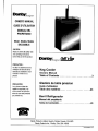
DKC645BLS
CAUTION:
Read end fodow all safety rules
and operaling instruchons
| before first use of this product.
PRECAUTION :
Vauikaz lire alenvemend les
consignes de sécurité af les
Instructions d'utilisation avant
l'utilisation initiale de ce
produit.
PRECAUCIÓN:
Lea y observe indas las
reglas de seguridad y las
instrucciones de operación
antes de usar este producto
por primera vez.
Danby;,.. er Chill nla
Keg Cooler
Owners Manual
Glaciére de biére pression
Guide d'utilisation
Barril Refrigerador
Manual del propietario
Table of Contents ......eoeeec0cemeo
Table des matiéres ................
TabladeContenido . ..................
Danby Products Limited, Guelph, Ontario Canada NTH 629
Danby Products Inc., Findlay, Ohio USA 45840
DICCAISELE 12,07
WELCOME
Welcome to the You'll see it in this Best of all, you'll
Danby family. We're easy-to-use manual experience these
proud of our quality and you'll hear it in values each time you
products and we the friendly voices of use your Keg Cooler.
believe in dependable our consumer service That's important,
service. department. because your new
Tel: 1-800-26- Danby” Keg Cooler will be
part of your family for
a long time.
Start Herel... Before using your Chill ‘N Tap Keg Cooler
Write down the model and serial Staple your receipt to the inside
numbers here, They are on a label back cover of this page. You will
located on the back of Ihe cabinel. need it to obtain service under
warranty.
Model number
Serial number
Date purchased ==
NEED HELP?
Before you call for service, Read this manual Save time and money
there are a few things you It contains instructions to Check the section titled “If
can do to help us serve help you use and maintain Something Goes wrong”
you batter... your keg cooler propery. before calling. This section
helps you solve common
If you received a problems that might occur.
damaged appliance If you do need service, you
immediately contact the can relax knowing help is
dealer (or builder) that sold only a phone call away.
you the appliance. Tel: 1-800-26- Danby"
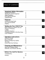
TABLE OF CONTENTS
Important Safety Information
Grounding Instructions 4
Warning CO, Can be Dangerous! =
Safety Precautions 5
Don't Wait Do This Now! 5
important Motice 5
Features a )
Knowing your Keg Cooler 6
Chil 'N Tap Accessories 7
Capacity 8
Setting Up Your Chill N’ Tap
Before putting your appliance into use g
Disposal of Packaging Э
Location 9
Assembly Instructions 10
Changing the Direction of the Door Swing 13
Castor Installation 13
Operation Instructions
Electronic Controls 14
Beer Temperature 14
Replace an Empty CO, Cylinder 15
Tap a Keg 15
Using Proper Draw Technique 16
Cleaning and Maintenance @ a
Keg Cooler, Dispense System 17
Glassware, CO» Pressure, Beer Keg 18
Before You Call For Service
Troubleshooting 19
Warranty 20
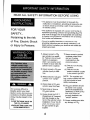
IMPORTANT SAFETY
INFORMATION
READ ALL SAFETY INFORMATION BEFORE USING
GROUNDING
INSTRUCTIONS
FOR YOUR
SAFETY...
Pertaining to the risk
of Fire, Electric Shock
or Injury to Persons.
* This appliance must be grounded. In the event of a
malfunction or breakdown, grounding will reduce the risk
ol electric shock by providing a path of least resistance
for electric current,
* This appliance is equipped with a power cord having an
equipment grounding conductor and grounding plug. The
plug must be plugged into an appropriate wall outlet that
& installed and grounded in accordance with all existing
local codes and ordinancas.
* Consult a qualified electriclan or serviceman If the
grounding instructions are not clearly understood, or if
doubt exist as to whether your electrical wall outlets are
property grounded
WARNING CO,
CAN BE *
DANGEROUS!
© ds Ci Ka EE TN Tr Ei,
i Не, rinden т A hial o = a
oh pel a. oh de
pu La he ha Te E
sh handied але г, Ta
ue = PL уе sd prope États FL se
per wing rocedurs BRET e e
re pull e a Ы wp i
installation;
a: SARA LAT AA La TE na
If it becomes difficult to
breathe and/or your head
starts to ache, abnormal con-
centrations of carbon dioxide
(62) may be present in the
Brea.
CLOSE THE MAIN VALVE ON
THE COs CYLINDER,
VENTILATE AND LEAVE THE
ROOM IMMEDIATELY!
1, Always connect a CO
gas cylinder to a regula-
tor. Failure to do so could
result in an explosion
which can possibly result
in death or injury when the
cylinder valve is opened
2. Never connect a CUs gas
cylinder directly to baer
Key. -
3. Always secure a CO» gas
cylinder in an "upnght”
DON.
4. Aways keep a CO» gas
cylinder away from heat.
8. Never drop or throw a
СО» gas cylinder,
6. Always check the DOT
(Department of Transport)
test date located on the
neck of the cylinder before
installation. H over five (5)
years, do not use, refum
the gas cylinder to gas
supplier,
4
T. Never connect a product
container unless there
are two (2} safety
mechanéem's In the
pressure system;
(a) One al ór on the CO»
regulator,
(b) One at or on the
product container coupler
In the pressure gas line.
NOTE: The regulator and
keg coupler supplied with this
unit are inclusive of such
safety mechanisms.
8. CO gas cylinders should
be stored in the coolest
part of the establishment
(preferably) al 70°F (21°C)
and must always be
securaly fastened in an
“upright” position.
9. Always ventilate area afier
any leakage of CO.
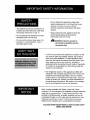
IMPORTANT SAFETY INFORMATION
NC nf
SAF ET - Go not defrost this appliance using other
PRECAUTIONS electric appliances (Le. hair dryer) and never
attempt to scrape or remove ica'frost
from the evaporator (cold plata) with sharp
* This appliance must be connected to a
properly grounded electrical outlet (see A
Grounding Instructions on pg. 4) - Always disconnect the appliance fram the
Do not operate this appliance if it has a power supply before cleaning andlor
attermpbing repairaiservicing.
damaged power cord or plug.
« Do no use this product near water, for paa Repalrs should be
example: in 8 wat basement, near a E
swimming pool or sink performed by qualified service
personnel only,
DON'T WAIT,
DO lls | o N ON - If wou have purchased this appliance to replace an old
ane remove althar tha gaskels, latches, lids or doors
Re RTE from the unused appliance. If it was equipped with a
eee déc EL of wo ся door lock that cannot be opened from (he inside, (lock
: SEE Зе bolt) make sure the lock is removed, disabled or
e EA desiroyed before discarding, this will make it impossible
A fH SET for children fo accidentally lock themselves inside the
ET ti to he appliance and suffocate.
= a =
o a A
- The refrigerator system of this appliance is fled wih
refngerant and insulating substances which should be
treated and processed separalely. Call your nearest
Service agent or specialized servicing center. If you are
unable to locate one, contact your local authorities for
proper disposal instructions. Be careful not to damage
any of the refrigeration lines of the appliance.
1 FPO AW Beer is easily available with Danby's new Keg Cooler,
N OTICE however, It is not intended to be available lo pecple under the
a = legal age to consume beer. A beer faucet lock kit for the
purpose of limiting access, is readily avallable and can be
purchased through our after sales service department (see
Optional Áccessones on pg 7. Danby does mot assume
liability for the unlawful use or consumption of the beer.
PLEASE DRINK RESPONSIBLY AND PLEASE DON'T
DRINK AND DRIVE!
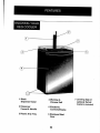
KNOWING YOUR
KEG COOLER
1 Black
Dispense Tower
Z Dispenser
Faucet & Handle
3 Plastic Drip Tray
4 Worktop & I Leveling legs or
Chrome Rail optional Swivel
Castors (included)
= Electronic
Controls/Display
6 Stainless Steel
Door
FEATURES
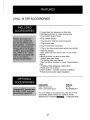
CHILL 'N TAP ACCESSORIES
INCLUDED
ACCESSORIES
2 Chrome Rails (for attachment to Work top)
4 Self-Tapping Screws (to attach chrome rails)
1 C04 Cylinder Support Stand
1 COs Cylinder (empty)
1 CO= Regulator (high/low pressure gages)
1 COs Air Line Hose
2 CO= Alr Line Hose Connectors
1 CO Air ine hose plug (located exterior rear cabinet)
1 Baer Kag Coupler
1 Baer Tower Unit (incl. faucel, hose, nut and rubber
washer)
4 Machine Screws (io attach to beer tower)
1 Gaskat (beer tower base)
1 Pull Handle (baer lowar faucet)
1 Baer Keg Stand {required for “squat” keg installations
andy)
1 Protective Plate {refrigerator cabinet floor)
1 Plastic Drip Tray (2 piece)
4 Swivel Casters - 2 locking- {optional installabon)
16 Machine Screws (for caster installation)
OPTIONAL
ACCESSORIES
Description Bart No,
Beer Faucet Lock, "03
These are NOT included Fi Beer Line Cleaning KIL FCLEANINGKIT
the CHILL 'N TAP, and must | | |
be MD sn For more details on purchasing any of the above listed
accessories, please contact our customer service
department at 1-800-26- Daniby" (1-800-263-2629),
FEATURES
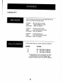
CAPACITY
There are threa (3) standard size beer kegs that can ba
used in your Chill 'N Tap Key Cooler;
1/2 Barrel: 585 Liter Keg (15.5 Gal)
Yields ; 7 cases (1984075) of beer
Keg Welght: 1701bs Full (approx.)
1/4 Barrel: 30 Lider Keg (7.75 Gal)
Yields: 3112 cases (992075) of beer
Keg Weight: &5fbs Full (approx.)
1/6 Barred: 20 Liter Kaq (5 Gal)
Yields: £-1/2 Cases (6400zs) of bear
Keg Weight: 60ibs Full (approx)
À fully charged (Sib) CO. cylinder wil service (approx. E
Quantity Keg Size
10 58.5 Liter Kegs (1/2 Barrels)
20 30 Liter Kegs (1/4 Barrels)
25 20 Liter Kegs (1/6 Barrels)
For the location of à CO. supplier in vour area,
(re-fills) please look in your "Yellow Page”
telephone directory under "OXYGEN" suppliers.
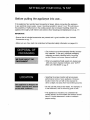
SETTING UP YOUR CHILL 'N TAP
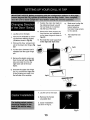
Before putting the appliance into use...
If the appliance has recently been transported or lipped, before connecting the appliance
io any elecirncal power supoly , leave it standing (upright) for about 1 hour. This will reduce
Ihe possibility of mailfuncions in the cooling system due to transport handling. Clean the
appliance thoroughly, both interior and exterior. (See “Cleaning and Maintenance ón pa. 177
IMPORTANT:
- Ensure that all included acosessories are present and in good condition (see Included
Accessortes ón pg. 7).
- Make suré vou have read end understood al important safety information on pages 4-5.
DISPOSAL OF Our products use environmentally friendly (recycla
PACKAGING ble) materials. To this end, individual packaging
materials are clearly identified with a recycling
symbol. Always use proper disposal methods.
- Yen any appliance finally wears oul, always usa
safe and proper disposal methods. (see “DONT
WAIT, DO THIS NOW or pg. 5
LOC AT | en + 5éléctng thé proper location will ensure pask
pertormance levels of your apoliance. Choose a
location where the unit will nol be exposed to
direct sunlight and away from haat emitting sources.
This appliance is designed for
"indoor" use only and should + Do not use this product near water, for example: in
not be used “outdoors”. a wel basement, near a swimming pool or sink.
* This appliance is inclusive of 8 condenser fan
coded cabinel, the front intake and exhaust should
hava 2-3 inches clearance in order lo maintam
Proper cooing.
SETTING UP YOUR CHILL N' TAF
ASSEMBLY
INSTRUCTIONS
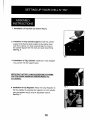
1. Installation of Top Rail: (as show In Fig 1).
à. Installation of CO, Cylinder Support: Install the cylinder
support onto the four studs located on the exterior back
wall of the cabmet. (mo tools required) Align the holes in
the cylinder support with the studs and push down firmly.
Sew Fig. 2
Fig. 1
4. Installation of CO; Cylinder: Install your " fully charged”
CO cylinder info he support stand.
| =
CAUTION WHEN HANDLING PRESSURIZED CO,
4. Installation of C0; Regulator: Attach the CO Regulator to
the Clg cylinder by screwing the regulator nut onto cylinder
valve and tighten (snug) using an adjustable wrench.
See Fig. 3
10
SETTING UP YOUR CHILL N' TAP
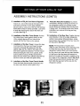
ASSEMBLY INSTRUCTIONS (CONT'D)
5. Installation of CD; Air Line Hose to Regulator:
Allach one end of the (red) air line hose to the
hose barb connection on the COs regulator.
Secure hose by using one of the two (self locking)
black plastic snap on clamps provided. (use pliers
to snap the clamp tight Io assure thal there are
no leaks) See Fig. 4
. Installation of the Beer Tower Gasket: Position
Ihe rubber (beer lower) gasket directly on top
of the cabinet aligning all four holes in the
gasket with the four holes on the cabinet.
Installation of the Beer Tower; Unravel the baer
line (hose) from the tower and insert the beer
line and nul through the gasket and ino the
cabinet. Align the four holes in the base of the
beer tower, gasket and bayonal. The beer faucet
should be facing the front of Ihe cabinet. (6:00
o'chock position) Using a Phillips Screwdriver,
aliach the beer tower to the cabinet using the four
machine Screws provided and tighten firmly
Installation of the Beer Tower Faucet Handle:
Screw the black faucet handle (clockwise) onto
the beer tower faucet. (hand tighten only)
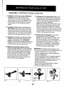
10.
Protective Plate (Pre-installed): To prevent
unnecessary damage (marring) to the floor of
the refrigerator cabinet, the protective plate
should always be installed when the keg stand
IS being usad. The protective plate also makes
Installation ard removal of he keg and keg
stand sasier.
Installation of the Beer Keg: Position the keg
stand directhy in front of the open refrigerator
cabinet. Using proper lifting technique, (using
keg handles only) carefully lift the bear keg onto
the keg stand. See Fig. 7
NOTE: The keg stand Is required when
using 30 Liter {1/4 barrel) “pony” style kegs only.
To install the baer keg and stand Inside the
refrigerator cabinet, brace your knees behind
the keg stand and grasp the keg stand handles.
Lift the front of the keg stand just enough so
that the front edge of the stand is resting on the
front edge of the refrigerator cabinel. See Fig. B
(Grasp the keg stand (front) handles and “care
fully” slide the keg stand all the wey into the
refrigerator cabinet.
11
SETTING UP YOUR CHILL N' TAP
ASSEMBLY INSTRUCTIONS (CONT'D)
1. Installation of the Keg Coupler: IMPORTANT
NOTICE; Make sure the pull handia of the
keg coupler ls in the "upywarnd” (closed) position
before: installing on the beer keg. See Fig. Y Insert
the keg coupler into the locking neck of the beer
keg and apply a 1/4 tum dockwise to lock into
position.
12. Installation of the CO. Air Line Hose to the
Keg Coupler; Attach the open end of the (red) air
line hose io he hose barb connection on Me Keg
Coupler. Secure hose by using the remalning (self
hocking) plastic snap on clamp provided, (use pliers
lo tighten clamp and assure there are no keaks)
13. Installation of the Beer Line Hose to the Keg
Coupler: Screw tha beer ine nut onto the keg
coupler and hand tighten firmly. IMPORTANT
NOTICE: The black rubber washer provided must be
installed meide the beer ine connection mut before
connecting the beer fine to the keg coupler,
14. Making the connection between the Keg
Coupler and Beer Keg: Before making (opening)
connection between the keg coupler and beer keg,
Make sure the bear tower faucet is in the dosed
position, (Faucet handle straight hack) To engage
the tank connection, pull the keg coupler handle
out and push down unt it locks Into position
Listen for positive “click” of the pull handle in the
final downward position. See Fig. 8
15. Opening the CO; Cylinder Main Valve: Before
opening the main valve located on top of the CO,
cylinder. Make sure the “secondary” shut-off valve
located on Ihe lower stem pipe of the regulator is
in the: “closed” position. See Fig. 9
NOTE: When the secondary valve (handle) ls posi-
Boned "Horizontal" (sastiwest) the valve is closed.
hen he secondary valve (handie) is positioned
Vertical" (north/south) the valve is Open. To open the
main COs cylinder valve, (slowly) turn the main valve
Counter clockwise until fully open. You will notice the
needles on both gauges star lo dimb.
16. Adjusting the CO, Regulator: There are two
préssuré gauges on ha CO- reguiator.
See Fig. 11 The upper gauge £1 monitors “LOW”
(internal keg) pressure and must be adjusted to
the comect operating pressure of 10-12psifbs, The
tower gauge 17 monitors "HIGH" (CO cylinder)
Pressure and is not adjustable. The high pressure
Gauge also acts as a fuel gauge to let you know
when the Clg oyinder needs re-filing,
IMPORTANT: The internal operating pressure of the
baer keg should be adjusted and maintained between 10
- Tzpsibs. To adjust the "icw” pressure game;
* Using an adjustable wwench, release the adjustment
lock nut £ 3. See Fig, 10
* Using à fal screwdriver, turn the regulator adjustment
screw # 4 See Fig. 10 Clockwise rotation of the
adjustment scraw will Increase low pressure. Counter
clockwise rotation of the adjustment screw will
decreass low pressure
* When the required operating pressure is attained
redighten the adjustment lock nut # 3.
* You are now ready 10 serve cold beer
Fig. 7 Flg. B
Fig. 10
SETTING UP YOUR CHILL N" TAP
hy a i pet te
7. Position the main door back on 10, Make sure to align the
srl, ging Direction the cabinet and push up until door and cabinet
я A | [oY | the top hinge pin ig inserted belore fastening
2 Door á'wini
of the Door wing into the top of the door. the lower hinge screws
8. Remove thé lower support pin lo the cabinet.
1. Lay the unit oñ its back. from hé door and réposibion il
on the lower hinge as shown in | 1". Re-install the kick-
a Remove the kickptate by remov- Fig. ES plate.
ing the three retaining screws.
{locations shown in Fig E 9. Re-install the lower suppor pin
on the right side of the door
3. Remove the four screws local
ad on the lower door hinge (Fig Fig.E3
EZ. — Fig.E4
„оо
4. Pull the door dowrnwand until it | \
releases from the upper hinge +, Л
аа
pin,
Remove the plastic crew cap
from the top left hand (Fig EN
Cr
side and install it on the top
right hand side of the door
frame.
6. Unscrew the upper door hinge
pin {Fig E4) from the right side
of the worktop and install it on
{he left side of thé workiop.
1. Lay Ihe uni on IT's back.
astor Installation
2. Remove Ihe found)
adjustable feet.
À. Castor Installation :
(as show in Fig A)
Fig.A
13
OPERATING INSTRUCTIONS
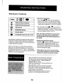
Electronic Controls
ET
Danby... vi EE
= —
TEMPERATURE INCREASE
| VW TEMPERATURE DECREASE
El) LED DISPLAY a 5
8 FAHRENHEIT MODE
Ox CELSIUS MODE
@ FAHRENHEITICELSIUS SELECTOR
The electronic control panel allows for total cabinet
lempéralure control as well as the option of displaying
\current) and modilying (setting) the cabinet temperature
in esther Fahrenheit or Celsius.
When you first plug in your Keg Coaler the LED will
display the Jive’ cabinet temperature in Fahrenheit and
the thermostat will be set to 41° F (5° C). The following
paragraphs will explain how to modify the aforementioned
séllings to suit your requirements;
Adjusting the temperature;
« Press either de WF button once and release bo
enter the SET mode, The LED display will begin
to flash and show the previous temperature setting
- signifying the temperature is ready to be adjusted.
+ Each depression of the 4 or WF will increase or
decrease the temperature incrementaily by 1° (FIC)
until he desired setting Is reached, The temperature
can be set between 36-46" F (2-8 Ci.
“Note: the display will flash for 5 seconds from
the time the last button was activated before
resuming display of the Internal temperature of
the cabinet.
Changing the temperature display;
' Press the MM: selector button lo altemate the
display between Fahrenheit and Celsius. The
corresponding plod light adjacent to the selector
will aluminate lo signify which unit of temperature
has bean selected for display
“Please Note: In the event of a power failure,
any modified settings are lost and the default
settings are restored once power resumes.
Beer Temperature
14
- Beer can freeze, so itis important lo select and
maintain proper operating temperatures Inside
the refrigerator cabinet. * Beer will start to
freeze at 28°F ( -2°C)
* Uiptimum temperatures for serving cold beer are
367 = 40° F {2% - 4° C)
Températures too cool or too warm may cause
flaver loss, off taste and dispensing problems.
» Periodically monitor temperatures inside your keg
cooler, (adjust as necessary)
* Heap the keg cooler door closed as much as
possible to avoid temperature fluctuations
OPERATING INSTRUCTIONS
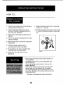
HOW TO...
Replace an Empty
F |
CO, Cylinder
1. Close the main cylinder valve (A) by tuming in a 9. Readjust regulator pressure (DD) (if necessary)
clockwise directon, See Fig. 11
. Close the secondary shut-off valve (C} by
turning to Torizontal” (eastwest) position on
lower stem pipe, See Fig.11
between 10 — 12 psilbs,
10. Open the secondary shut-off valve (C)by tuming
to “vertical” (north/south) positon on lower stem
pipe.
3. Remove the air ine clamp and hose from the — o
regulador.
4. Remove the regulalor assembly (E) from empty
cylinder. See Fig. 11
5, Remove dust cap from new and/or replacement
СО cylinder
8. Re-altach regulator assembly (E) Eo
newreplacaement cylinder. See Fig.11
7. Re-aftach the airline hose to regulator (bart
connection) and secure with clamp,
Fig. 11
8. Slowly open main valve (À) all the way.
Sea Fig. 11
« Prior to lapping the keg, ensure the beer faucet is in
Tap a Keg the off position.
i - Completely remove the dust cover (identification cap)
from the beer keg.
« Check that the keg coupler (handle) is in tha up (off)
position. See Fig. 7
+ Insert the keg coupler into tha locking neck of the beer
keg and apply à turn clockwise to lock Into position,
« Pull keg coupler handle out and downward until it locks
ino position. See Fig. 8 This activates both the beer and
(CO) pressure line.
The keg is now tapped and ready to draw beer.
15
OPERATING INSTRUCTIONS
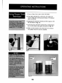
Using Proper Draw
Technique
1 т
au 1 Er
E EE + =
| ges Le ee. E “e
) Sr E Но dea
o $ to unnece sy wil
Be est as PE CRAQUE are ©
“the disner
wh ¡e НН Ре gos
E
He
TE и:
=F J
dE
Pa LLY я.
1. Rinse a "Beer Clean” glass under cold water,
2. Place glass baneath tap, and tilt at a 45° angle. (as
shown in Fig. 12) Leaving approximately 1/4" between
glass and faucet.
3. Fully draw the dispenser handie and fill Ihe glass to 273
full. (as shown in Fig. 13).
4. Level the glass and finish topping off by continuing the
pour in the center of the glass. (as shown in Fig. 14)
3. Make sure the handle is fully relumed to it's previous
‘off position when the draw is complete.
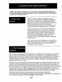
CLEANING AND MAINTENANCE...
Regular cleaning and maintenance is a key factor in safe guarding the longevity of
the keg, the quality of the dispensed beer as well as trouble free day to day operation
of your Chill 'N Tap Keg Cooler.
of the Keg « There is no need to defrost the refrigerator, beacause ice
E = ue depositing on the evaporator is defrosted automatically. Ice
Cooler build-up on the evaporator during compressor operation;
will (when the compressor has cyced off) defrost automatically.
Defrost water collects inside the drain trough and
passes through the drain outlet in the rear wall nto a drain
pan situated above the compressor, where it evaporates.
Always disconnect the power cord before cleaning and/or
servicing the appliance, Do not use coarse or aggressive
cleaning agents as they can damage the control panel
andor painted surfaces, Clean the exterior cabinet with
warm water and a mild detergent. Clean the interior with
warm water and a mild detergent, adding one oF two
spoonfuls of vinagar. After cleaning, connect the appliance
to power supply
- If you do not intend to use the appliance for lóng pañods of
time, disconnect the power cord. Clean the appliance and
leave the door slightly open to reduce moldimikdew from
accumulating mside the cabinet.
... of the Dispense
System
Beer lines have to penodically be cleaned because of a crystallized build up which forms on the fittings,
lines and taps commóny refarrad tó as "beerstore". IF he “beerstore” is not completely removed in a
cleaning process il will leave an unsanitary surface that can harbor microorganisms which will cause an
undesirable favor andlor cause the beer to go fiat, Sufficient “beerstore” will also lead to dispense
problems ranging from ‘wild’ beer (too much foam) to flat beer, regardless of the carbonation levels or
quality (age) of the beer in the keg.
Scheduled line and fáucet cleaning, with the proper equipment and chemical, eliminates the build-up of
“beerstore™ protacting the intagrity of the product and condition of the dispense system and seals. The
dispanser (beer) ne should ba cleansed approximately once every three (3) weeks or every other keg -
which ever comes first, The dispenser fauce! should be cleaned on a weekly basis or prior fo every use if
nol used on a regular basis. Note: If you have trouble manipulating the faucet laver, this is usually
indicative that it may require cleaning, *DO NOT apply force to move the handle in this situation, as this
will likely lead to damaging the handle and/or faucet, and will not be covered by your warranty.
À standard cleaning kit will perform approximately elght (6) scheduled line cleanings.
Line cleaning kits are readily avallable and can be purchased through our after sales service department.
For more information please call 1-800 26-DANBY (1-800-263-2620)
17
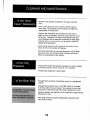
CLEANING AND MAINTENANCE...
. of the "Beer * Maintain strict sanitary conditions in the glass washing
Clean” Glassware Ek
- Never wash glassware with utensils or dishes used to
serve food, Food particles andlor residue can effect the
qualitytaste of draught beer.
- Regular dish defergents are fat-besed and will leave a
slight oily film on the glass, which will cause the beer fo go
flat quickly. Therefore, it is highly recommended that vou
use a detergent that is designed spacifically for beer glass
cleaning which Is cdor-free and non-fat based. instead of
regular liquid detergents.
= Avoid drying glassware with towels as thay tend to leave
traces of lint on the surface of the glass,
* We recommend that you use beer glassware only for baer.
Dalry and other food products leave a residue which can
affect the qualitytaste of the draught
| of ne C КО oF
В | operating pressures remain constant. (10-12psiibs)
- Always keep equipment in good repair
MORIN S = 4-16] - Draught Beer should be immediately stored in a refrigerated
cabinet
- Draughi Beer products have à shelf life, which on "average"
15 30 days after the k&g is tapped. By keeping the beer keg
pressurized, (with CO.) and with proper maintenance of the
dispense system, the shelf life can be extended to approximatly
60 days (or more).
* Beer Kags should be stored (refrigerated) saparately from
other food products.
18
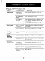
BEFORE YOU CALL FOR SERVICE
TROUBLESHOOTING
Problem
Excess formation of
Fossible Causes
Recent keg agitation
What To Do
If the keg has recently been moved (transporiad), you
foam ‘head. should bet it stand for a minimum of two (2) hours
before tapping.
Improper regulator verify hal he 'LOYW' side (CO) pressure is reading
selling between 10 — 12 psi.
Internal temperature ol Ensure that the keg cooler Is operating within 36 - 40°
Reg Cooer jar bear keg) — p (2.47 Ch If the beer key has been exposad Io a
log warm. warm environment for an extended period, give it
sufficient lime lo cool before attempting a pour.
Pressure build up Activate the pressure redial valve that is located on the
keg coupler for 3 seconds.
Improper draw lechnique see "Using Proper Draw Technique” on pg. 16.
Flat Draft. no noir réputé Verify that ihe "LOW side (CO) pressure ls reading
formation of foam.
sexing
Glassware 15 mail
"Beer Chan”
between 10 = 12 0.5.1,
Residue on glassware in the form of cils will quickly
dizsolve the formation of foam, (see "Beer Clean
Glassware” on pg. 18)
Elongated dispensing
hase,
All recommended temperatures and gauge Seflings ans
calculated for a dispensing hose five (5) feet in length.
LowEmpty CO cylinder,
Check that HIGH pressure gauge Is. not reading “0”
paí. Refill if necessary.
Mo bear flow from
dispensar
Closed CO, valve and/or
Shiul-0d valve,
Ensure thal bath he CO cylinder and regulator shaut-
off valve are open.
Empty CO cylinder.
Check thal 'HIGH' pressure gauge is not reading “0°
psi. Refill f necessary.
Empty beer keg.
Replace beer keg.
Line or dispensar
Verify that there are no ‘kinks’ or obstructions In either
obstructions. the air line (red) or dispenser line (clear) and that
neither are frozen
Improper connections) Ensure all connections are secure and all seals are in
19
place and in good condition.
BEFORE YOU CALL FOR SERVICE
TROUBLESHOOTING (Cont'd)
Problem Possible Causes What To Do
Sputtering draw Dispense system See "Cleaning and Maintenance” on pg. 17-18
requires cleaning.
Keg Coupler insialiad Check seal between keg & faucet
incormeciy
Line or dispenser Venfy that there are no ‘kinks’ or obstructions in either
obstructons, the air line (red) or dispenser line (clear) and that
neither are frozen
improper draw technique See Using Proper Draw Technique” on pg. 16.
Faucal Dripping Handle not fully retumed After every pour, ensure the handie is relumed fo the
to close postion, the off position.
Faucet requires cleaning. See "Cleaning and Maintenance” on pg. 17-18
Rapid CO; cylinder improper conneclion, air Ensure proper connection of airline at COZ regulator.
discharge lime leak. and/or check air line for possible leaks
uid Faucet requires cleaning See "Cleaning and Maintenance” on pg. 17-18
Faucet handle
Damaged handle stem . Remove handle, and connector nuts and Inspect stem
for possible damage
Abnormal baér
Cispense system Sea “Cleaning and Maintenance” on pg. 17-18
taste andror smell requires cleaning.
Contaminated dispense Check hoses for possible aw leaks, Ensure all
System, conneciions aná secure and all seals are in place and
in good condition.
The beer has exceeded Replace Beer Кедр.
d's sholé-life
20
Th TS = SE = PE (= PE ME CACA Pa
ña e
EA
"E 3
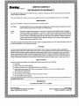
e LIMITED COMPACT A
A re
2 REFRIGERATOR WARRANTY E
A e.
К This quay product e imarramed le be lea from manufacturera defects in material and workmanship, provided Dai Fe unit is sed under Ihe она орет i
ci condibons intended ty fe macufactunar. Ge
hes E
6 This warranty le avadable onty lo the parson fo whom the uni ear orignaly sold by Danby of by an aulhorized distsbutor of Cena, and la nonranslenatls. 00
EXA Pr
53 TERMS OF WARRANTY (0)
ZA =
6 Piestic paria, are weranted for than (90) days oniy bom purchase data, wilh no edensions provides, 0)
В E
i) First 748 Months During the fret sighizen | 18] manths, ey siechical parts of this preduct loud lo be deleciiva, including any sealed system uni, willbe o
wag saan of seplaces, af mamanior's optica, at no change lo the ORIGINAL perchaser Sa
e O
К То даю Danby recarese Me right lo lime the boundaries of Y= Home Service” fn tre гоу с а Asthoszed Senace Decol Airy appéance Si
(6) Seme equiing bervioe outside Ihe limited boundaries of in Hom Send 1 wil ba the consumer's responsiziity lo transpor ie appliaaco (at 60)
re thelr own expansa| to the anginal retailer pois! of purchasel or à sersce depot for repair, Contact your dealer from whom your uni was Y
(x) curchesét, dr contact pour neavest authortes Danby sonics dapat, wham service mist Ce paricrmad by e msalibicd seno: hechracian. Le
Pe F service Sera о he una bi amore cer Ian an aubcrized sence depor. or he Ur is used tor commercial application, al oo
(x) chligatons o? Dantry urder fis warranty chal be at an ned №
A ir
de, >
x) Mothing witin this wasmanty shall imply hal Dendy will be responsible or dable for 2my spolane or damage tn food or ofa contents of this aspirante. wielte: des ©)
wy 0 any detect of fo appliance, or ils use, wher proper of im propL. a
E E
A EXCLUSIONS ho at
(x) e )
Fe Save as herein provider, Darty Prodacis Limited (Canada) or Dante Products inc: (USA), ere ara no other wamaeles, condiions, epresantalions or E
A quaremees, express or mpiled, made or elended try Canby Procuds Limied oris asthoszéd detrindors andal aer wamanbés. Dondéons, reprecentabons or CA
o quenanbaes, incucing asy vasanties, cordiéons, representations or ueraniees under arm Sa of Goods Actor lap legrsiabon or slatus is Seedy expressly vo
Lay exchudod. Save as haria providod, Dany Producis Limied (Canada) dr Denty Prodecis Ine. [LLS A), stali mot he responsible fos any damages 10 persons on A
Ne amp, Include le unk sc howacever caused or ary eoeeguarldemapes aising em e allncionl We rl and y fe puehase el e une e
es cunde dere hereby agree ls Ndemiy and save harmieza Dentay Products Limied from any cs fi damages lo persons or property caused by the chil №
ve es
Со Mo warranty or meurance ferai comand or se oul shall apply when damage of mper 16: саней by emy of Me НОСЫ 6
pos 1) Роме Fairs. be
(es te
o 3) Damage in trans orwhes modag Ihe appliancs. NA
я J) Improper power supply ва ния bow votene, defects house wong of inadequate fuses. Fo
A dj Accident aieator, abuse 06 misuse of the appliance such As radequale air cimuliion in he mom of abnormal opereliag coadions, EA
7 3 (éeciremety igh oF ow mar am Tan]. ton |
ANA 5) Use lor commercial orindustial perposes A
i
x 8) Firm, water carriage, Bell, sear, fol, пов, ве of God such a humicaes, Moods Bic 6)
E 7) Eervice calls realing in customer éducation 2
(x) Proof of ourchass dele id ba segured for waranty claims; 50, pisase man bis of sain. in the Sven mamar; Service | required, present Te document 12 aur e.
CS AUTHORIZED SERVICE DEPOT. be)
<5 ih es ©
E In Home Service on models 3.0 cu. fl, ог greater, (5
o - 6
e FO Box T778, SOTO Whileior BS, Cueiph, Ontrio, Carada Mii 629 FO fan 680, 101 Beriley Couri, Fraliry, Obia, USA. SEE Le
CH Telephone: [5191 857-0600 FAI (519 7-340 nat Teéephone: 4119) 425-6627 FAX: (170) 42-38 65
x [le &
; с
x
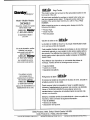
Danby...
Model + Modèle Modelo
DKC645BLS
For service, contact your means!
Service depot or calt
1-800-26-
(1-800-263-2629)
16 recommend a depot in
your area,
En cas de réparation, veuillez
comacter votre service
après-vente le plus près ou
COTITIUNIQUEZ SL
1-800-26-
(1-800-263-2629)
pour connaître l& saris
après-vente le plus proche.
Para obtener servicio,
comuniquese con al
establecimiento de servicio
más cercano o llame al:
1-800-26-
(1-800-263-2629)
para que le recomendemds Ur
establecimiento de su zona,
Chill'n lap «og Cooler
The mode! number can be found on the serial plate located on the
back panel of the unit.
All repair parts available for purchase or special order when you
visit your nearest service depot. To request service and/or the
location of the service depot nearest you, call the TOLL FREE
NUMBER.
When requesting service or ordering parts, always provide the
following information:
= Product Type
* Model Number
« Far Descnpbon
Glacière de biére en «or Chill'n lap
Le numéro du modéle se trouve sur la plaque d'identification située
sur le panneau arrière de l'appareil.
Il est possible d'acheter les pièces de rechange ou de les obianir par
commande spéciale eñ vous rendant à votre service après-vente le
plus proche. Pour effectuer des réparations ou obtenir l'adrassé du
service après-vente le plus proche, veuillez composer le NUMERO
SANS FRAIS.
Four éffectuer des répærations ou commander des pièces de
rechange, veuillez donner les renseignements suivants :
« Type de modèle
*« Numéro du modèle
= Description des pièces
Refrigerador de Barril СЫ! lap
El número de modelo se ancuenira en la placa de serle, ubicada en
el tablero posterior de la unidad,
Puede comprar lodos Ios repuestos o hacer un pedido especial
visitando el establecimiento de servicio más cercano a su domicilio,
Lame al TELÉFONO GRATUITO para oblener servicio de
mantenimiento o la dirección del establecimiento de servicio más
cercano a St domécilio,
Siempre, al solicitar sevicio de mantenimiento 6 hacer un pedido de
repuestos, debe suministrar la siguiente Información:
« Tipo de artefacto
« Número de modelo
" Descripción del repuesto
Danby Products Limiled, Guelph, Ontario Canada N1H 679
Danby Products Inc, Findlay, Ohio USA 45840
PIRINTED IN ZHEJIANG CHINA [PRC | IMPREME БМ ZHEJIANG CHE (PREC) IMPRESED EN ZHEJIANG CHINA (P.R.C.}