1
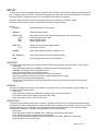
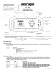
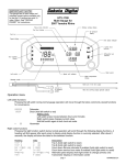
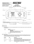
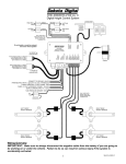
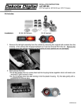
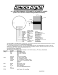
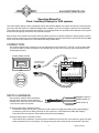
Operating Manual for
Clock / Auxiliary Displays for VHX systems
The VHX auxiliary display module is designed to work with a Dakota Digital VHX system and will not function properly
on its own. With this module, an additional display area is added to your current system to provide more functionality.
This module can be used as a simple clock display or it can display data from any BIM module attached to the system
as well as several gauge values from the control box sensors.
Most versions of this module come with at least one switch in the face to allow the display to change between various
screens. Some versions may also contain two additional switches in the face which can be used as the SW1 and SW2
for the VHX control box with the use of the switch harness provided with it.
CONNECTION:
The auxiliary display has a connector on the rear that will accept a normal CAT 5, CAT 5E, or CAT 6 patch cable.
This can be used to connect the module to any available port on the VHX control box (same locations the main
VHX gauges plug into).
Auxiliary Display module
VHX
control
box
DISPLAY
CABLE
AUX.
I/O
VHX
CONTROL BOX
OR
ORANGE
SWITCH HARNESS:
SW1 (-)
SW2 (-)
ADJ ADJ SND
WTR WTR SND
Used for displays
with 3 switches
OIL OIL SND
OIL +
FUEL FUEL SND
FUEL +
www.dakotadigital.com
[email protected]
605-332-6513
SPD OUT
SPD SPD SND
SPD +
Connection for all
auxiliary displays
DIM (+)
CHECK ENG (-)
BRAKE (-)
HIGH (+)
LEFT (+)
WARN
RIGHT (+)
TACH
4x4 (-)
ACC. POWER
GEAR (1 WIRE)
CONST. POWER
WAIT (+)
GROUND
CRUISE (-)
Use any open jack
GREEN
ORANGE (switch 1)
Some auxiliary modules will come with the
pictured switch harness to allow additional
switches in the clock face to function as switch
1 and 2 for the main VHX system.
GREEN (switch 2)
BLUE (switch 3)
Auxiliary modules with 3 switches on front:
Connect the orange wire to SW1(-) terminal on VHX control box. Right switch will be SW1 (speed display).
Connect the green wire to SW2(-) terminal on VHX control box. Left switch will be SW2 (tach display).
Leave blue wire unconnected. Center switch will be SW3 (clock display)
Auxiliary modules with no switches on front:
If the module has no switches, connect an external switch from the blue wire of the harness to ground to allow
switch operations for the clock display. The orange and green wires would be left unconnected in this case.
1
MAN #650360
SETUP:
To enter setup, press and hold the switch (for systems with 3 switches, hold the center switch) while turning on the
key. The display will read “SETUP”. Release the switch and the setup menu will be entered. Below is an outline of
the setup options. Following the outline are more detailed instructions for each option.
Press and release the switch to move through the various setup options or to change a setting.
Press and hold the switch to select a setup option or to save a changed setting.
SETUP
CONTRAST
Allows adjustment of LCD contrast.
VERSION
Displays software version
UPDATE SPD
SLOW
MED
FAST
Sets update speed of fast changing displayed data (such as tachometer)
Slowest update speed of data
Medium update speed
Fastest update speed
TEMP UNIT
F or C
Selects unit used for temperature displays
Fahrenheit or Celsius
SCREENS
Allows turning different display screens on or off
SET DEFAULTS
Sets all the settings back to factory default values
DONE
Leaves setup and returns to normal operation.
CONTRAST:
This option allows adjustment of the display contrast to best suit the particular mounting location in your vehicle.
Enter setup.
Press and release switch until “CONTRAST” is displayed, then press and hold switch
“CONTRAST” will display with a contrast bar below it.
Press and hold the switch to increase the contrast.
Release the switch and press and hold again to reduce the contrast.
Each time the switch is release the direction of contrast adjustment will change.
Once contrast is set stop pressing the switch.
After about 5 seconds without a switch press the contrast setting will be saved and setup will return to the
main menu.
VERSION:
This option will display the version of the software in the display module. This information may be needed if you
are calling for technical assistance.
Enter setup.
Press and release switch until “VERSION” is displayed, then press and hold switch.
The software version will be displayed (example: VER VC01).
Press and release switch to return to main menu.
UPDATE SPD:
This option sets the fastest update speed of screens. The effect will be most noticed when the tachometer screen
is displayed. The fastest setting will allow frequent updates so the reading is more accurate at any given time. Fast
changing readings may be difficult to read or distracting so some customers prefer to read a slower averaged
reading which is available in the MED or SLOW setting. Default setting is MED.
Enter setup.
Press and release switch until “UPDATE SPD” is displayed, then press and hold switch.
Press and release switch to toggle through speed settings.
Press and hold switch when desired setting is displayed to save setting. “DONE” will be displayed.
Release switch to return to main menu.
2
MAN #650360
TEMP UNIT:
This setting determines which temperature unit is used when displaying temperatures. This unit setting will be
independent of the units used in the main VHX system and may be used to provide and alternate display unit from
the main VHX screens if so desired. Default setting is Fahrenheit.
Enter setup.
Press and release switch until “TEMP UNIT” is displayed, then press and hold switch.
Press and release switch to toggle between F (Fahrenheit) and C (Celsius)
Press and hold switch to select displayed setting. “DONE” will be displayed.
Release switch to return to main menu.
SCREENS:
This option allows customization of the displayed values. You may independently select any screens you wish to
be “ON” or “OFF” during normal operation. If a screen is set to “ON”, it will be included in the sequence of screens
displayed when you press the switch in normal operation. If a screen is set to “OFF” this screen will be skipped
over when you move through the screens. This is helpful for reducing the number of screens you must scroll
through in normal operation by preventing the display of screens that you don’t want to see or that are already set
to display in the main VHX system screens.
Enter setup.
Press and release switch until “SCREENS” is displayed, then press and hold switch.
Press and release switch to move through available screens.
Press and hold switch to toggle screen setting between “ON” and “OFF”
Once screens are set as desired, press and release switch until “SCREENS DONE” is displayed. Then press
and hold the switch to save the changes to screen setup.
If the key is turned off before “SCREENS DONE” is selected, the new screen settings will not be saved.
NOTE: If all screens with displayable data are set to “OFF”, a message will appear during normal operation stating
that no data is available for current screens and that more screens should be turned on. In this case, go to the
screens option and turn on more screens to prevent this message.
SET DEFAULTS:
This option allows all the settings to be returned back to the factory defaults. This may be helpful to get back to a
known starting place with the settings. This may also be a step in troubleshooting issues so the technician will
have consistent settings to work from.
NOTE: This option will reset all settings to factory defaults, including the contrast setting and it will also zero any
clock offset that may be set.
Enter setup.
Press and release switch until “DEFAULT” is displayed, then press and hold switch.
Display will read “RESET TO DEFAULTS? N”
Press and release switch so display reads “RESET TO DEFAULTS? .Y”
Press and hold switch to reset defaults. “DONE” will be displayed.
Release switch to return to main menu.
DONE:
This option will leave setup and return to normal operation. Alternatively, the key may be turned off at any point in
the main menu of setup and settings will be saved. If key is turned off while setting an option, the new settings may
not be saved.
Press and hold switch when “SETUP DONE” is displayed. “DONE” will display in large font.
Release switch to leave setup and return to normal operation.
NORMAL OPERATION:
In its normal operation, this auxiliary display module provides an additional display to your main VHX system. This
display can display a clock, several of the main system gauge values and data from any connected BIM expansion
unit. This section describes how to operate this display module in its normal operating mode.
BACKLIGHTING / DIMMING:
The backlighting and dimming for the display are controlled by the main VHX system. Use the main system setup
to make changes to the backlighting and dimming behavior.
3
MAN #650360
AVAILABLE SCREENS:
Some screen data should always be available to this module from most VHX systems. These screens are:
Clock
Engine Temp
Oil Pressure
Fuel Level
Tachometer
Speed (MPH)
Speed (km/hr)
Additionally, depending on the configuration of your main VHX system, many other screens may also be available
(many of these readings require additional sensors and or BIM expansion modules) including:
Gear Position
Compass
Various temperature readings
Various pressure readings
More readings may be available from BIM modules
By default all screens are set to “ON” but only screens with data available will be displayed.
WARNING POINTS:
Warnings for the main system values (Engine Temp, Oil Pressure, Fuel, and Tachometer) will not be displayed in
this auxiliary module as they are provided on the main VHX system. However, BIM modules that have the internal
warning points (set in VHX main system setup) will flash if they are currently being displayed and they are in a
warning condition.
CHANGING SCREENS:
Various screens of information are available to the auxiliary display from the VHX system. To display a different
screen simply press and release the switch. The display will change to the next screen selected in the “SCREENS”
list in setup that has data available. Screens that are set to “OFF” in setup or that don’t currently have data
available will be skipped.
NOTE: All the information displayed on this module comes from the main VHX system. If the information needed
for a particular screen is not provided by the system (a BIM module becomes disconnected for instance) the
display may show “???” to indicate information is no longer available for that screen. Pressing the switch will move
the screen to next available screen with available data.
SCREEN SPECIAL FUNCTIONS:
Some screens have additional special functions. To use these special functions press and hold the switch. One
screen that has a special function is the clock screen. Holding the switch on the clock screen allows setting the
clock offset (see “CLOCK” section for details). Additional special functions for BIM modules, if any, are described
in the BIM module manual.
CLOCK:
CLOCK SOURCE AND SETTING CLOCK:
This auxiliary module does not keep its own time. Instead it uses either the VHX system time or the time from a
BIM-16 clock module (if connected). For most applications, it is recommended to set the clock on the VHX system
or set the BIM-16 time if it is being used.
NOTE: Due to system limitations, if all 16 BIM expansion channels of the VHX system are in use and none of them
provide time information (such as BIM-16) a clock reading may not be available to display on this module.
24 HOUR CLOCK:
The main VHX system clock is only a 12hr clock. If a 24 hour clock display is desired, a BIM-16 clock expansion
module may be purchased from Dakota Digital. This module will connect to the BIM expansion jack of the VHX
control box and can be set in the main system setup. If a BIM-16 is connected to the VHX system, this auxiliary
display module will automatically read clock data from the BIM-16.
NOTE: If the clock offset is used with a 24 hour clock source, the displayed time will be forced to a 12 hour clock.
4
MAN #650360
USING CLOCK OFFSET:
Because this auxiliary module displays the clock, it may be desired to disable the display of the clock on the main
VHX screens. This makes it much more difficult to adjust the VHX clock because the main VHX system requires
the clock screen to be displayed to set it.
To make clock adjustment more convenient in this situation, a clock offset may be set on this module. The steps
are the same as setting the main VHX clock but it is done using the switch for this auxiliary module instead. It is
important to note that the VHX time is not changed with this method. Instead a time offset from the main system
time is set. If the main VHX clock display is enabled, this method will cause this time to be different than that
displayed in the VHX system displays.
With the clock screen displayed, press and hold the switch. The hour will begin to flash.
Press and release the switch to adjust the hours.
Press and hold the switch to move to tens of minutes. Tens of minutes will begin flashing.
Press and release the switch to adjust the tens of minutes.
Press and hold the switch to move to the single minutes. Single minutes will begin flashing.
Press and release the switch to adjust the single minutes.
Press and hold the switch to apply the offset and return to normal display.
NOTE: If the VHX system clock time or the BIM-16 clock time is adjusted, the auxiliary module clock offset will
automatically be reset to zero so the time displays are resynchronized.
Troubleshooting guide.
Problem
Display reads “NO DATA
FROM CONTROL CHECK
CONNECTIONS AND FOR
BROKEN WIRES”
Display randomly moves
through screens and
repeatedly displays
“DAKOTA DIGITAL”
Display is very dark or light
and difficult to read
Can’t display desired screen
Display reads “NO DATA
AVAILABLE FOR CURRENT
SCREENS TURN MORE
SCREENS ON”
Screen displays “???”
instead of a reading
Auxiliary module doesn’t
light up or display anything
System no longer displays
clock
Or
Clock displays “??:??”
Possible cause
Patch cable not fully plugged into
module or VHX control box.
Solution
Ensure to push the cable into the connector until the cable “clicks” into place.
If the tab on the cable appears damaged a new CAT 5, 5E, or CAT 6 PATCH
cable should be used.
BIM module cable not fully plugged
into a BIM module.
Push all BIM module cables firmly into the jack to make sure they are fully
seated.
VHX display cable or BIM module
cable is broken or pinched.
Auxiliary module received no data at
startup and has reverted to a DEMO
mode.
Inspect all cables for nicks or cuts or for wear marks or pinched locations.
Replace questionable / damaged cables. Reroute cables away from harm.
Turn key off to stop demo mode and see “Display reads ‘NO DATA FROM
CONTROL CHECK CONNECTIONS AND FOR BROKEN WIRES’” for
solutions to the no data problem.
VHX system is in demo mode
Contrast needs to be adjusted
This module will enter demo mode if the VHX system is in demo mode.
See “SETUP” section for instructions on adjusting the screen contrast.
Screen is turned off in screen setup
Follow steps under “SCREENS” in setup section to verify setting
Data is not available for display
If screen is from a BIM module, ensure it is connected and functioning
properly and that no other BIM modules are set to use the same channel.
Follow steps under “SCREENS” in setup section to turn on one or more
screens to display.
All screens that have available data
are set to “OFF” in setup
Data for that screen is no longer
available. Such as BIM module
losing power or connection to
system. A BIM channel may also
have been changed or over
crowded.
Unit not connected to main VHX
system.
16 BIM channels in use.
BIM module channels have been
changed
If the screen selected is a reading from a BIM module, check that the BIM
module is connected and functioning properly.
If the channel of the BIM has been changed, turn the key off and then back
on so the VHX system can search for the correct channel. Also verify that the
new channel isn’t already used by another BIM unit.
Ensure that a patch cable is connecting the jack of the auxiliary unit to one of
the display jacks on the VHX control box.
If all 16 BIM channels are in use, there is no longer time to send clock data
out. To get clock data back, at least one BIM channel must be left open or be
a BIM-16 clock module.
Turn the key off then back on to allow the VHX system to relearn the new
BIM channel locations.
5
MAN #650360
SERVICE AND REPAIR
DAKOTA DIGITAL offers complete service and repair of its product line. In addition, technical
consultation is available to help you work through any questions or problems you may be having installing
one of our products. Please read through the Troubleshooting Guide. There, you will find the solution to
most problems.
Should you ever need to send the unit back for repairs, please call our technical support line, (605)
332-6513, to request a Return Merchandise Authorization number. Package the product in a good
quality box along with plenty of packing material. Ship the product by UPS or insured Parcel Post. Be sure
to include the RMA number on the package, and include a complete description of the problem with RMA
number, your full name and address (street address preferred), and a telephone number where you can be
reached during the day. Any returns for warranty work must include a copy of the dated sales receipt from
your place of purchase. Send no money. We will bill you after repair.
Dakota Digital Limited Lifetime Warranty
DAKOTA DIGITAL warrants to the ORIGINAL PURCHASER of this product that should it, under
normal use and condition, be proven defective in material or workmanship for the lifetime of the original
vehicle it was installed in, such defect(s) will be repaired or replaced at Dakota Digital’s option.
This warranty does not cover nor extend to damage to the vehicle’s systems, and does not cover
removal or reinstallation of the product. This Warranty does not apply to any product or part thereof which
in the opinion of the Company has been damaged through alteration, improper installation, mishandling,
misuse, neglect, or accident.
This Warranty is in lieu of all other expressed warranties or liabilities. Any implied warranties,
including any implied warranty of merchantability, shall be limited to the duration of this written warranty. No
person or representative is authorized to assume, for Dakota Digital, any liability other than expressed
herein in connection with the sale of this product.
6
MAN #650360