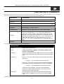
1
CLI Manual
Product Model :
TM
DES-6500
Modular Layer 3 Chassis Ethernet Switch
Release 3
Table of Contents
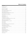
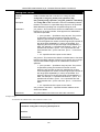
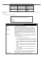
Introduction ............................................................................................................................................ 1
Using the Console CLI ............................................................................................................................. 4
Command Syntax.................................................................................................................................... 8
Basic Switch Commands ....................................................................................................................... 10
Switch Port Commands ......................................................................................................................... 25
Port Security Commands....................................................................................................................... 28
Network Management (SNMP) Commands............................................................................................. 31
Switch Utility Commands ...................................................................................................................... 52
Network Monitoring Commands ............................................................................................................ 58
Multiple Spanning Tree Protocol (MSTP) Commands ............................................................................. 75
Forwarding Database Commands.......................................................................................................... 89
Broadcast Storm Control Commands .................................................................................................... 97
QoS Commands .................................................................................................................................. 102
Port Mirroring Commands ................................................................................................................... 114
VLAN Commands ................................................................................................................................ 118
Link Aggregation Commands............................................................................................................... 127
IP Commands (Including Multiple IP interfaces per VLAN)................................................................... 134
IGMP Commands (Including IGMP v3)................................................................................................. 139
IGMP Snooping Commands................................................................................................................. 143
Access Authentication Control Commands .......................................................................................... 152
SSH Commands .................................................................................................................................. 176
SSL Commands................................................................................................................................... 184
802.1X Commands ............................................................................................................................. 190
Access Control List (ACL) Commands (Including CPU)......................................................................... 209
Safeguard Engine Commands ............................................................................................................. 235
Traffic Segmentation Commands......................................................................................................... 238
D-Link Single IP Management Commands........................................................................................... 240
Time and SNTP Commands ................................................................................................................. 251
ARP Commands .................................................................................................................................. 257
VRRP Commands ................................................................................................................................ 261
Routing Table Commands ................................................................................................................... 268
Route Redistribution Commands ........................................................................................................ 271
DHCP Relay Commands ...................................................................................................................... 277
DNS Relay Commands ........................................................................................................................ 283
RIP Commands ................................................................................................................................... 287
DVMRP Commands............................................................................................................................. 290
PIM Commands................................................................................................................................... 295
IP Multicasting Commands ................................................................................................................. 299
MD5 Configuration Commands ........................................................................................................... 301
OSPF Configuration Commands .......................................................................................................... 303
Jumbo Frame Commands ................................................................................................................... 323
Command History List ........................................................................................................................ 325
Technical Specifications ...................................................................................................................... 328
xStack DES-6500 Modular Layer 3 Chassis Ethernet Switch CLI Manual
1
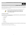
I NTRODUCTION
The xStack DES-6500 layer 3 modular chassis Ethernet switch is a member of the D-Link xStack family. Ranging from
10/100Mbps edge switches to core gigabit switches, the xStack switch family has been future-proof designed to provide a
stacking architecture with fault tolerance, flexibility, port density, robust security and maximum throughput with a user-friendly
management interface for the networking professional.
The Switch can be managed through the Switch’s serial port, Telnet, or the Web-based management agent. The Command Line
Interface (CLI) can be used to configure and manage the Switch via the serial port or Telnet interfaces.
This manual provides a reference for all of the commands contained in the CLI. Configuration and management of the switch
via the Web-based management agent is discussed in the User’s Guide.
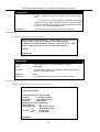
Accessing the Switch via the Serial Port
The Switch’s serial port’s default settings are as follows:
•
115200 baud
•
no parity
•
8 data bits
•
1 stop bit
A computer running a terminal emulation program capable of emulating a VT-100 terminal and a serial port configured as
above is then connected to the Switch’s serial port via an RS-232 DB-9 cable.
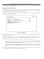
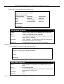
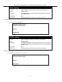
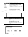
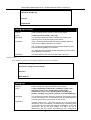
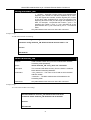
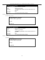
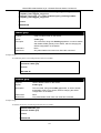
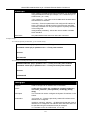
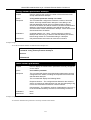
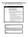
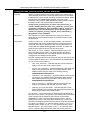
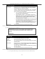
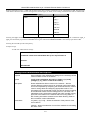
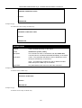
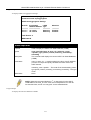
With the serial port properly connected to a management computer, the following screen should be visible. If this screen does
not appear, try pressing Ctrl+r to refresh the console screen.
Figure 1-1. Initial CLI screen
1
xStack DES-6500 Modular Layer 3 Chassis Ethernet Switch CLI Manual
There is no initial username or password. Just press the Enter key twice to display the CLI input cursor − DES-6500:4#. This is
the command line where all commands are input.
Setting the Switch’s IP Address
Each switch must be assigned its own IP Address, which is used for communication with an SNMP network manager or other
TCP/IP application (for example BOOTP, TFTP). The Switch’s default IP address is 10.90.90.90. You can change the default
switch IP address to meet the specification of your networking address scheme.
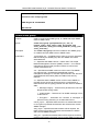
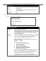
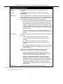
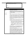
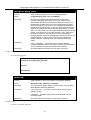
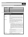
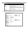
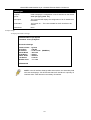
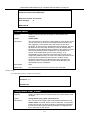
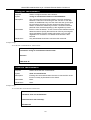
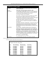
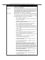
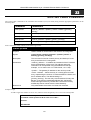
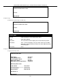
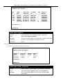
The Switch is also assigned a unique MAC address by the factory. This MAC address cannot be changed, and can be found on
the initial boot console screen – shown below.
Figure 1-2. Boot Screen
The Switch’s MAC address can also be found in the Web management program on the Switch Information (Basic Settings)
window on the Configuration menu.
The IP address for the Switch must be set before it can be managed with the Web-based manager. The Switch IP address can be
automatically set using BOOTP or DHCP protocols, in which case the actual address assigned to the Switch must be known.
The IP address may be set using the Command Line Interface (CLI) over the console serial port as follows:
1.
Starting at the command line prompt, enter the commands config ipif System ipaddress
xxx.xxx.xxx.xxx/yyy.yyy.yyy.yyy. Where the x’s represent the IP address to be assigned to the IP interface named
System and the y’s represent the corresponding subnet mask.
2.
Alternatively, you can enter config ipif System ipaddress xxx.xxx.xxx.xxx/z. Where the x’s represent the IP address
to be assigned to the IP interface named System and the z represents the corresponding number of subnets in CIDR
notation.
The IP interface named System on the Switch can be assigned an IP address and subnet mask which can then be used to connect
a management station to the Switch’s Telnet or Web-based management agent.
2
xStack DES-6500 Modular Layer 3 Chassis Ethernet Switch CLI Manual
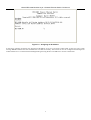
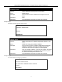
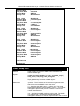
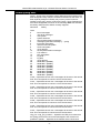
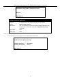
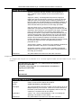
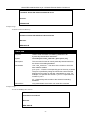
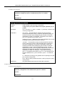
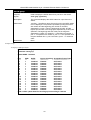
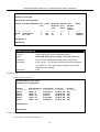
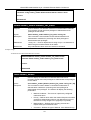
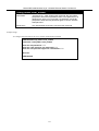
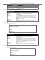
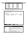
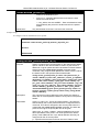
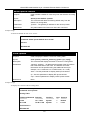
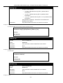
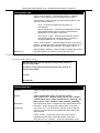
Figure 1-3. Assigning an IP Address
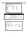
In the above example, the Switch was assigned an IP address of 10.53.13.144 with a subnet mask of 255.0.0.0. The system
message Success indicates that the command was executed successfully. The Switch can now be configured and managed via
Telnet and the CLI or via the Web-based management agent using the above IP address to connect to the Switch.
3
xStack DES-6500 Modular Layer 3 Chassis Ethernet Switch CLI Manual
2
U SING THE C ONSOLE CLI
The XStack DES-6500 supports a console management interface that allows the user to connect to the Switch’s management
agent via a serial port and a terminal or a computer running a terminal emulation program. The console can also be used over the
network using the TCP/IP Telnet protocol. The console program can be used to configure the Switch to use an SNMP-based
network management software over the network.
This chapter describes how to use the console interface to access the Switch, change its settings, and monitor its operation.
Note: Switch configuration settings are saved to non-volatile RAM using
the save command. The current configuration will then be retained in the
Switch’s NV-RAM, and reloaded when the Switch is rebooted. If the
Switch is rebooted without using the save command, the last configuration
saved to NV-RAM will be loaded.
Connecting to the Switch
The console interface is used by connecting the Switch to a VT100-compatible terminal or a computer running an ordinary
terminal emulator program (e.g., the HyperTerminal program included with the Windows operating system) using an RS-232C
serial cable. Your terminal parameters will need to be set to:
•
VT-100 compatible
•
115200 baud
•
8 data bits
•
No parity
•
One stop bit
•
No flow control
You can also access the same functions over a Telnet interface. Once you have set an IP address for your Switch, you can use a
Telnet program (in VT-100 compatible terminal mode) to access and control the Switch. All of the screens are identical,
whether accessed from the console port or from a Telnet interface.
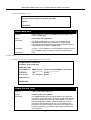
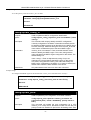
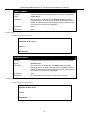
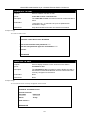
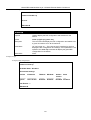
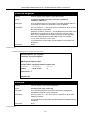
After the Switch reboots and you have logged in, the console looks like this:
4
xStack DES-6500 Modular Layer 3 Chassis Ethernet Switch CLI Manual
Figure 2-1. Initial Console Screen
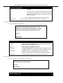
Commands are entered at the command prompts, DES-6500:4#.
There are a number of helpful features included in the CLI. Entering the ? command will display a list of all of the top-level
commands.
Figure 2-2. The ? Command
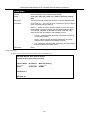
When entering a command without its required parameters, the CLI will prompt you with a Next possible completions:
message.
5
xStack DES-6500 Modular Layer 3 Chassis Ethernet Switch CLI Manual
Figure 2-3. Example Command Parameter Help
In this case, the command config account was entered with the parameter <username>. The CLI will then prompt to enter the
<username> with the message, Next possible completions:. Every command in the CLI has this feature, and complex
commands have several layers of parameter prompting.
In addition, after typing any given command plus one space, you can see all of the next possible sub-commands, in sequential
order, by repeatedly pressing the Tab key.
To re-enter the previous command at the command prompt, press the up arrow cursor key. The previous command will appear at
the command prompt.
Figure 2-4. Using the Up Arrow to Re-enter a Command
In the above example, the command config account was entered without the required parameter <username>, the CLI returned
the Next possible completions: <username> prompt. The up arrow cursor control key was pressed to re-enter the previous
command (config account) at the command prompt. Now the appropriate User name can be entered and the config account
command re-executed.
All commands in the CLI function in this way. In addition, the syntax of the help prompts are the same as presented in this
manual − angle brackets < > indicate a numerical value or character string, braces { } indicate optional parameters or a choice of
parameters, and brackets [ ] indicate required parameters.
6
xStack DES-6500 Modular Layer 3 Chassis Ethernet Switch CLI Manual
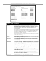
If a command is entered that is unrecognized by the CLI, the top-level commands will be displayed under the Available
commands: prompt.
Figure 2-5. The Available Commands Prompt
The top-level commands consist of commands such as show or config. Most of these commands require one or more parameters
to narrow the top-level command. This is equivalent to show what? or config what? Where the what? is the next parameter.
For example, if you enter the show command with no additional parameters, the CLI will then display all of the possible next
parameters.
Figure 2-6. Next possible completions: Show Command
In the above example, all of the possible next parameters for the show command are displayed. At the next command prompt,
the up arrow was used to re-enter the show command, followed by the account parameter. The CLI then displays the user
accounts configured on the Switch.
7
xStack DES-6500 Modular Layer 3 Chassis Ethernet Switch CLI Manual
3
C OMMAND S YNTAX
The following symbols are used to describe how command entries are made and values and arguments are specified in this
manual. The online help contained in the CLI and available through the console interface uses the same syntax.
Note: All commands are case-sensitive. Be sure to disable Caps Lock or
any other unwanted function that changes text case.
<angle brackets>
Purpose
Encloses a variable or value that must be specified.
Syntax
create ipif <ipif_name> <network_address> <vlan_name 32>
{secondary | state [enabled | disabled]}
Description
In the above syntax example, the user must supply an IP
interface name in the <ipif_name> space, a VLAN name in the
<vlan_name 32> space, and the network address in the
<network_address> space. Do not type the angle brackets.
Example Command
create ipif Engineering 10.24.22.5/255.0.0.0 Design
[square brackets]
Purpose
Encloses a required value or set of required arguments. One
value or argument can be specified.
Syntax
create account [admin | user] <username 15>
Description
In the above syntax example, you must specify either an admin
or a user level account to be created. Do not type the square
brackets.
Example Command
create account admin
| vertical bar
Purpose
Separates two or more mutually exclusive items in a list, one of
which must be entered.
Syntax
create account [admin | user] <username 15>
Description
In the above syntax example, you must specify either admin, or
user. Do not type the vertical bar.
Example Command
show snmp community
8
xStack DES-6500 Modular Layer 3 Chassis Ethernet Switch CLI Manual
{braces}
Purpose
Encloses an optional value or set of optional arguments.
Syntax
reset {[config | system]}
Description
In the above syntax example, you have the option to specify
config or system. It is not necessary to specify either optional
value, however the effect of the system reset is dependent on
which, if any, value is specified. Therefore, with this example
there are three possible outcomes of performing a system
reset. See the following chapter, Basic Commands for more
details about the reset command.
Example command
reset config
Line Editing Key Usage
Delete
Backspace
Left Arrow
Right Arrow
Up Arrow
Down Arrow
Tab
Deletes the character under the cursor and then shifts the
remaining characters in the line to the left.
Deletes the character to the left of the cursor and shifts the
remaining characters in the line to the left.
Moves the cursor to the left.
Moves the cursor to the right.
Repeat the previously entered command. Each time the up
arrow is pressed, the command previous to that displayed
appears. This way it is possible to review the command history
for the current session. Use the down arrow to progress
sequentially forward through the command history list.
The down arrow will display the next command in the command
history entered in the current session. This displays each
command sequentially as it was entered. Use the up arrow to
review previous commands.
Shifts the cursor to the next field to the left.
Multiple Page Display Control Keys
Space
CTRL+c
ESC
n
p
q
r
a
Enter
Displays the next page.
Stops the display of remaining pages when multiple pages are to
be displayed.
Stops the display of remaining pages when multiple pages are to
be displayed.
Displays the next page.
Displays the previous page.
Stops the display of remaining pages when multiple pages are to
be displayed.
Refreshes the pages currently displayed.
Displays the remaining pages without pausing between pages.
Displays the next line or table entry.
9
xStack DES-6500 Modular Layer 3 Chassis Ethernet Switch CLI Manual
4
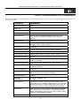
B ASIC S WITCH C OMMANDS
The basic switch commands in the Command Line Interface (CLI) are listed (along with the appropriate parameters) in the
following table.
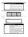
Command
Parameters
create account
[admin | user] <username 15>
config account
<username 15>
show account
delete account
<username 15>
show config
[current_config | config_in_NVRAM]
show session
show switch
show device status
show serial_port
config serial_port
{auto_logout [never | 2_minutes | 5_minutes | 10_minutes |
15_minutes]}
enable clipaging
disable clipaging
enable telnet
<tcp_port_number 1-65535>
disable telnet
enable web
<tcp_port_number 1-65535>
disable web
save
reboot
reset
{[config | system]}
login
logout
config
command_prompt
[<string 16> | username | default]
config
greeting_message
{default}
show
greeting_message
Each command is listed, in detail, in the following sections.
10
xStack DES-6500 Modular Layer 3 Chassis Ethernet Switch CLI Manual
create account
Purpose
Used to create user accounts.
Syntax
create [admin | user] <username 15>
Description
The create account command is used to create user accounts
that consist of a username of 1 to 15 characters and a password
of 0 to 15 characters. Up to 8 user accounts can be created.
Parameters
admin <username> - Entering this parameter will give the
specified user administrative-level privileges over configuring
functions of the Switch. This user may perform any function listed
in this manual. A username of up to 15 characters must be
created with this command to identify the admin user.
user <username> - Entering this parameter will give the specified
user user-level privileges over configuring functions of the Switch.
User-level privileges limit the execution of many commands listed
in this manual. A username of up to 15 characters must be
created with this command to identify the user.
Restrictions
Only Administrator-level users can issue this command.
Usernames can be between 1 and 15 characters.
Passwords can be between 0 and 15 characters.
Example usage:
To create an administrator-level user account with the username “dlink”.
DES-6500:4#create account admin dlink
Command: create account admin dlink
Enter a case-sensitive new password:****
Enter the new password again for confirmation:****
Success.
DES-6500:4#
config account
Purpose
Used to configure user accounts
Syntax
config account <username>
Description
The config account command configures a user account that
has been created using the create account command.
Parameters
<username>- Enter the username of the account to be configured.
Restrictions
Only Administrator-level users can issue this command.
Usernames can be between 1 and 15 characters.
Passwords can be between 0 and 15 characters.
Example usage:
To configure the user password of “dlink” account:
11
xStack DES-6500 Modular Layer 3 Chassis Ethernet Switch CLI Manual
DES-6500:4#config account dlink
Command: config account dlink
Enter a old password:****
Enter a case-sensitive new password:****
Enter the new password again for confirmation:****
Success.
DES-6500:4#
show account
Purpose
Used to display user accounts.
Syntax
show account
Description
Displays all user accounts created on the Switch. Up to 8 user
accounts can exist on the Switch at one time.
Parameters
None.
Restrictions
None.
Example usage:
To display the accounts that have been created:
DES-6500:4#show account
Command: show account
Current Accounts:
Username
--------------dlink
Access Level
-----------Admin
DES-6500:4#
delete account
Purpose
Used to delete an existing user account.
Syntax
delete account <username>
Description
The delete account command deletes a user account that has
been created using the create account command.
Parameters
<username>- Enter the username of the account to be deleted.
Restrictions
Only Administrator-level users can issue this command.
Example usage:
To delete the admin account “System”:
12
xStack DES-6500 Modular Layer 3 Chassis Ethernet Switch CLI Manual
DES-6500:4#delete account System
Command: delete account System
Are you sure to delete the last administrator account?(y/n)y
Success.
DES-6500:4#
Example usage:
To delete the user account “System2”:
DES-6500:4#delete account System2
Command: delete account System2
Success.
DES-6500:4#
show config
Purpose
Used to display a list of configuration commands entered into the
Switch.
Syntax
show config [current_config | config_in_NVRAM]
Description
This command displays a list of configuration commands entered
into the Switch.
Parameters
current_config – Entering this parameter will display configurations
entered without being saved to NVRAM.
config_in_NVRAM - Entering this parameter will display
configurations entered and saved to NVRAM.
Restrictions
None.
Example usage:
To view configurations entered on the Switch that were saved to NVRAM:
13
xStack DES-6500 Modular Layer 3 Chassis Ethernet Switch CLI Manual
Command: show config config_in_NVRAM
#-----------------------------------------------------------------------------------------------------#
DES-6500 Configuration
#
#
Firmware: Build 3.00-B29
#
Copyright(C) 2004-2007 D-Link Corporation. All rights reserved.
#-----------------------------------------------------------------------------------------------------# BASIC
config serial_port baud_rate 115200 auto_logout never
enable telnet 23
enable web 80
enable clipaging
# STORM
config traffic control 1:1-1:26 broadcast disable multicast disable dlf disable
threshold 128
config traffic control 2:1-2:24 broadcast disable multicast disable dlf disable
CTRL+C ESC q Quit SPACE n Next Page ENTER Next Entry a All
show session
Purpose
Used to display a list of currently logged-in users.
Syntax
show session
Description
This command displays a list of all the users that are logged-in at
the time the command is issued.
Parameters
None.
Restrictions
None.
Example usage:
To display the way that the users logged in:
DES-6500:4#show session
Command: show session
ID
-*8
Live Time From
Level Name
---------------------- ------------------03:36:27 Serial Port 4
Anonymous
Total Entries: 1
CTRL+C ESC q Quit SPACE n Next Page ENTER Next Entry a All
14
xStack DES-6500 Modular Layer 3 Chassis Ethernet Switch CLI Manual
show switch
Purpose
Used to display information about the Switch.
Syntax
show switch
Description
This command displays information about the Switch.
Parameters
None.
Restrictions
None.
Example usage:
To display the Switch information:
DES-6500:4#show switch
Command: show switch
Device Type
: DES-6500 Chassis Ethernet Switch
Unit ID
:1
MAC Address
: DA-10-21-00-00-01
IP Address
: 10.41.44.22 (Manual)
VLAN Name
: default
Subnet Mask
: 255.0.0.0
Default Gateway
: 0.0.0.0
Boot PROM Version : Build 00170B20
Firmware Version : Build 2.00-B29
Hardware Version : 2A1
Device S/N
:
System Name
: DES-6500_#3
System Location
: 7th_flr_east_cabinet
System Contact
: Julius_Erving_212-555-6666
Spanning Tree
: Disabled
GVRP
: Disabled
IGMP Snooping
: Disabled
802.1X
: Disabled
Jumbo Frame
: Off
Clipaging
: Enabled
Port Mirror
: Disabled
SNTP
: Disabled
DHCP Relay
: Disabled
DNSR Status
: Disabled
VRRP
: Disabled
DVMRP
: Disabled
PIM-DM
: Disabled
RIP
: Disabled
OSPF
: Disabled
TELNET
: Enabled (TCP 23)
WEB
: Enabled (TCP 80)
RMON
: Enabled
HOL Prevention State : Enabled
Syslog Global State : Disabled
DES-6500:4#
15
xStack DES-6500 Modular Layer 3 Chassis Ethernet Switch CLI Manual
show device_status
Purpose
Used to display the current status of the hardware of the Switch.
Syntax
show device_status
Description
This command displays the current status of the Switch’s physical
elements.
Parameters
None.
Restrictions
None.
Example usage:
To show the current hardware status of the Switch:
DES-6500:4#show device_status
Command: show device_status
RPS1 Status:
Output voltage: Normal
FAN1: Normal
FAN2: Normal
RPS2 Status:
Not Exist
System FAN1:
System FAN2:
System FAN3:
System FAN4:
Normal
Normal
Normal
Normal
DES-6500:4#
show serial_port
Purpose
Used to display the current serial port settings.
Syntax
show serial_port
Description
This command displays the current serial port settings.
Parameters
None.
Restrictions
None.
Example usage:
To display the serial port settings:
DES-6500:4#show serial_port
Command: show serial_port
Baud Rate
Data Bits
Parity Bits
Stop Bits
Auto-Logout
: 115200
:8
: None
:1
: 10 mins
DES-6500:4#
16
xStack DES-6500 Modular Layer 3 Chassis Ethernet Switch CLI Manual
config serial_port
Purpose
Used to configure the serial port.
Syntax
config serial_port {auto_logout [never | 2_minutes |
5_minutes | 10_minutes | 15_minutes]}
Description
This command is used to configure the serial port’s baud rate
and auto logout settings.
Parameters
auto_logout – The user may select a time period from the
following list which the Switch will automatically log out of the
serial port.
Restrictions
•
never − No time limit on the length of time the console can
be open with no user input.
•
2_minutes − The console will log out the current user if
there is no user input for 2 minutes.
•
5_minutes − The console will log out the current user if
there is no user input for 5 minutes.
•
10_minutes − The console will log out the current user if
there is no user input for 10 minutes.
•
15_minutes − The console will log out the current user if
there is no user input for 15 minutes.
Only administrator-level users can issue this command.
Example usage:
To configure baud rate:
DES-6500:4#config serial_port baud_rate 115200
Command: config serial_port baud_rate 115200
Success.
DES-6500:4#
enable clipaging
Purpose
Used to pause the scrolling of the console screen when the show
command displays more than one page.
Syntax
enable clipaging
Description
This command is used when issuing the show command which
causes the console screen to rapidly scroll through several
pages. This command will cause the console to pause at the end
of each page. The default setting is enable.
Parameters
None.
Restrictions
Only administrator-level users can issue this command.
Example usage:
To enable pausing of the screen display when the command output reaches the end of the page:
17
xStack DES-6500 Modular Layer 3 Chassis Ethernet Switch CLI Manual
DES-6500:4#enable clipaging
Command: enable clipaging
Success.
DES-6500:4#
disable clipaging
Purpose
Used to disable the pausing of the console screen scrolling at
the end of each page when the show command displays more
than one screen of information.
Syntax
disable clipaging
Description
This command is used to disable the pausing of the console
screen at the end of each page when the show command
would display more than one screen of information.
Parameters
None.
Restrictions
Only administrator-level users can issue this command.
Example usage:
To disable pausing of the screen display when show command output reaches the end of the page:
DES-6500:4#disable clipaging
Command: disable clipaging
Success.
DES-6500:4#
enable telnet
Purpose
Used to enable communication with and management of the
Switch using the Telnet protocol.
Syntax
enable telnet <tcp_port_number 1-65535>
Description
This command is used to enable the Telnet protocol on the
Switch. The user can specify the TCP or UDP port number the
Switch will use to listen for Telnet requests.
Parameters
<tcp_port_number 1-65535> − The TCP port number. TCP
ports are numbered between 1 and 65535. The “well-known”
TCP port for the Telnet protocol is 23.
Restrictions
Only administrator-level users can issue this command.
Example usage:
To enable Telnet and configure port number:
DES-6500:4#enable telnet 23
Command: enable telnet 23
Success.
DES-6500:4#
18
xStack DES-6500 Modular Layer 3 Chassis Ethernet Switch CLI Manual
disable telnet
Purpose
Used to disable the Telnet protocol on the Switch.
Syntax
disable telnet
Description
This command is used to disable the Telnet protocol on the
Switch.
Parameters
None.
Restrictions
Only administrator-level users can issue this command.
Example usage:
To disable the Telnet protocol on the Switch:
DES-6500:4#disable telnet
Command: disable telnet
Success.
DES-6500:4#
enable web
Purpose
Used to enable the HTTP-based management software on the
Switch.
Syntax
enable web <tcp_port_number 1-65535>
Description
This command is used to enable the Web-based management
software on the Switch. The user can specify the TCP port
number the Switch will use to listen for Telnet requests.
Parameters
<tcp_port_number 1-65535> − The TCP port number. TCP ports
are numbered between 1 and 65535. The “well-known” port for
the Web-based management software is 80.
Restrictions
Only administrator-level users can issue this command.
Example usage:
To enable HTTP and configure port number:
DES-6500:4#enable web 80
Command: enable web 80
Note: SSL will be disabled if web is enabled.
Success.
DES-6500:4#
19
xStack DES-6500 Modular Layer 3 Chassis Ethernet Switch CLI Manual
disable web
Purpose
Used to disable the HTTP-based management software on the
Switch.
Syntax
disable web
Description
This command disables the Web-based management software
on the Switch.
Parameters
None.
Restrictions
Only administrator-level users can issue this command.
Example usage:
To disable HTTP:
DES-6500:4#disable web
Command: disable web
Success.
DES-6500:4#
save
Purpose
Used to save changes in the Switch’s configuration to non-volatile
RAM.
Syntax
save
Description
This command is used to enter the current switch configuration into
non-volatile RAM. The saved switch configuration will be loaded into
the Switch’s memory each time the Switch is restarted.
Parameters
Entering just the save command will save only the Switch configuration
to NV-Ram.
Restrictions
Only administrator-level users can issue this command.
Example usage:
To save the Switch’s current configuration to non-volatile RAM:
DES-6500:4#save
Command: save
Saving all configurations to NV-RAM… Done.
DES-6500:4#
NOTE: The DES-6500 does not support a change in box mode from Auto
to Static.
20
xStack DES-6500 Modular Layer 3 Chassis Ethernet Switch CLI Manual
reboot
Purpose
Used to restart the Switch.
Syntax
reboot
Description
This command is used to restart the Switch.
Parameters
None.
Restrictions
None.
Example usage:
To restart the Switch:
DES-6500:4#reboot
Command: reboot
Are you sure want to proceed with the system reboot? (y/n)
Please wait, the Switch is rebooting...
reset
Purpose
Used to reset the Switch to the factory default settings.
Syntax
reset {[config | system]}
Description
This command is used to restore the Switch’s configuration to the
default settings assigned from the factory.
Parameters
config − If the keyword ‘config’ is specified, all of the factory
default settings are restored on the Switch including the IP
address, user accounts, and the Switch history log. The Switch
will not save or reboot.
system − If the keyword ‘system’ is specified all of the factory
default settings are restored on the Switch. The Switch will save
and reboot after the settings are changed to default. Rebooting
will clear all entries in the Forwarding Data Base.
If no parameter is specified, the Switch’s current IP address, user
accounts, and the Switch history log are not changed. All other
parameters are restored to the factory default settings. The Switch
will not save or reboot.
Restrictions
Only administrator-level users can issue this command.
Example usage:
To restore all of the Switch’s parameters to their default values:
DES-6500:4#reset config
Command: reset config
Success.
DES-6500:4#
21
xStack DES-6500 Modular Layer 3 Chassis Ethernet Switch CLI Manual
login
Purpose
Used to log in a user to the Switch’s console.
Syntax
login
Description
This command is used to initiate the login procedure. The user
will be prompted for his Username and Password.
Parameters
None.
Restrictions
None.
Example usage:
To initiate the login procedure:
DES-6500:4#login
Command: login
UserName:
logout
Purpose
Used to log out a user from the Switch’s console.
Syntax
logout
Description
This command terminates the current user’s session on the
Switch’s console.
Parameters
None.
Restrictions
None.
Example usage:
To terminate the current user’s console session:
DES-6500:4#logout
config command_prompt
Purpose
Used to configure the command prompt for the Command Line
Interface.
Syntax
config command_prompt [<string 16> | username | default]
Description
This command is used to configure the command prompt for the
CLI interface of the Switch. The current command prompt
consists of “product name + : + user level + product name” (ex.
DES-6500:4#). The user may replace all parts of the command
prompt, except the # by entering a string of 16 alphanumerical
characters with no spaces, or the user may enter the current
login username configured on the Switch.
Parameters
<string 16> - Enter an alphanumeric string of no more than 16
characters to define the command prompt for the CLI interface.
username – Entering this parameter will replace the current CLI
command prompt with the login username configured on the
22
xStack DES-6500 Modular Layer 3 Chassis Ethernet Switch CLI Manual
config command_prompt
Switch.
default – Entering this parameter will return the command
prompt to its original factory default setting.
Restrictions
The reset command will not alter the configured command
prompt, yet the reset system command will return the command
prompt to its original factory default setting.
Only administrator-level users can issue this command.
Example usage:
To configure the command prompt:
DES-6500:4#config command prompt Trinity
Command: config command prompt Trinity
Success.
Trinity#
config greeting_message
Purpose
Used to configure the greeting message or banner for the
opening screen of the Command Line Interface.
Syntax
config greeting_message {default}
Description
This command is used to configure the greeting message or
login banner for the opening screen of the CLI.
Parameters
default – Adding this parameter will return the greeting command
to its original factory default configuration.
Restrictions
The reset command will not alter the configured greeting
message, yet the reset system command will return the
greeting message to its original factory default setting.
The maximum character capacity for the greeting banned is 6
lines and 80 characters per line. Entering Ctrl+W will save the
current configured banner to the DRAM only. To enter it into the
FLASH memory, the user must enter the save command.
Only administrator-level users can issue this command.
Example usage:
To configure the greeting message:
23
xStack DES-6500 Modular Layer 3 Chassis Ethernet Switch CLI Manual
DES-6500:4#config greeting_message
Command: config greeting_message
Greeting Messages Editor
===============================================================================
DES-6500 Chassis Ethernet Switch
Command Line Interface
Firmware: Build 3.00-B29
Copyright(C) 2004-2007 D-Link Corporation. All rights Reserved
===============================================================================
<Function Key>
Ctrl+C Quit without save
Ctrl+W Save and quit
<Control Key>
left/right/
up/down
Move cursor
Ctrl+D
Delete line
Ctrl+X
Erase all setting
Ctrl+L
Reload original setting
-----------------------------------------------------------------------------------------------------------------------------------------Success.
DES-6500:4#
show greeting_message
Purpose
Used to view the currently configured greeting message
configured on the Switch.
Syntax
show greeting_message
Description
This command is used to view the currently configured greeting
message on the Switch.
Parameters
None.
Restrictions
None.
Example usage:
To view the currently configured greeting message:
DES-6500:4#show greeting_message
Command: show greeting_message
=========================================================================
DES-6500 Chassis Ethernet Switch
Command Line Interface
Firmware: Build 3.00-B14
Copyright(C) 2004-2007 D-Link Corporation. All rights Reserved
=========================================================================
Success.
DES-6500:4#
24
xStack DES-6500 Modular Layer 3 Chassis Ethernet Switch CLI Manual
5
S WITCH P ORT C OMMANDS
The switch port commands in the Command Line Interface (CLI) are listed (along with the appropriate parameters) in the
following table.
Command
Parameters
config ports
[<portlist> | all] {speed [auto | 10_half | 10_full | 100_half | 100_full
| 1000_full {[master | slave | None]} | flow_control [enabled |
disabled] | learning [enabled | disabled] state [enabled | disabled] |
description <desc 32> | clear]}
show ports
{<portlist>} {description}
Each command is listed, in detail, in the following sections.
config ports
Purpose
Used to configure the Switch’s Ethernet port settings.
Syntax
[<portlist> | all] {speed [auto | 10_half | 10_full | 100_half |
100_full | 1000_full {[master | slave | None]} | flow_control
[enabled | disabled] | learning [enabled | disabled] state
[enabled | disabled] | description <desc 32> | clear]}
Description
This command allows for the configuration of the Switch’s
Ethernet ports. Only the ports listed in the <portlist> will be
affected.
Parameters
all − Configure all ports on the Switch.
<portlist> − Specifies a range of ports to be configured. The port
list is specified by listing the lowest switch number and the
beginning port number on that switch, separated by a colon. Then
the highest switch number, and the highest port number of the
range (also separated by a colon) are specified. The beginning
and end of the port list range are separated by a dash. For
example, 1:3 specifies switch number 1, port 3. 2:4 specifies
switch number 2, port 4. 1:3-2:4 specifies all of the ports between
switch 1, port 3 and switch 2, port 4 − in numerical order.
auto − Enables auto-negotiation for the specified range of ports.
[10 | 100 | 1000] − Configures the speed in Mbps for the specified
range of ports.
[half | full] − Configures the specified range of ports as either fullor half-duplex.
[master | slave | None] – The master and slave parameters refer
to connections running a 1000BASE-T cable for connection
between the Switch port and other device capable of a gigabit
connection. The master setting will allow the port to advertise
capabilities related to duplex, speed and physical layer type. The
master setting will also determine the master and slave
relationship between the two connected physical layers. This
relationship is necessary for establishing the timing control
between the two physical layers. The timing control is set on a
master physical layer by a local source. The slave setting uses
loop timing, where the timing comes form a data stream received
25
xStack DES-6500 Modular Layer 3 Chassis Ethernet Switch CLI Manual
config ports
from the master. If one connection is set for 1000 master, the
other side of the connection must be set for 1000 slave. Any other
configuration will result in a link down status for both ports. None
denotes the Switch will serve no role for stacking.
flow_control [enabled | disabled] – Enable or disable flow control
for the specified ports.
learning [enabled| disabled] − Enables or disables the MAC
address learning on the specified range of ports.
state [enabled | disabled] − Enables or disables the specified
range of ports.
description <desc 32> - Enter an alphanumeric string of no more
than 32 characters to describe a selected port interface.
clear – Enter this command to clear the port description of the
selected port(s).
Restrictions
Only administrator-level users can issue this command.
Example usage:
To configure the speed of port 3 of unit 1 to be 10 Mbps, full duplex, learning and state enable:
DES-6500:4#config ports 1:1-1:3 speed 10_full learning enabled state enabled
Command: config ports 1:1-1:3 speed 10_full learning enable stated enabled
Success.
DES-6500:4#
show ports
Purpose
Used to display the current configuration of a range of ports.
Syntax
show ports {<portlist>} {description}
Description
This command is used to display the current configuration of a
range of ports.
Parameters
{<portlist>} − Specifies a range of ports to be displayed. The port
list is specified by listing the lowest slot number and the beginning
port number on that slot, separated by a colon. Then the highest
slot number, and the highest port number of the range (also
separated by a colon) are specified. The beginning and end of the
port list range are separated by a dash. For example, 1:3 specifies
slot number 1, port 3. 2:4 specifies slot number 2, port 4. 1:3-2:4
specifies all of the ports between slot 1, port 3 and slot 2, port 4 −
in numerical order.
{description} – Adding this parameter to the command will allow
the user to view previously configured descriptions set on various
ports on the Switch.
Restrictions
None.
Example usage:
To display the configuration of all ports on a standalone switch:
26
xStack DES-6500 Modular Layer 3 Chassis Ethernet Switch CLI Manual
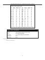
DES-6500:4#show ports
Command: show ports
Port
Port
Settings
Connection
Address
State
Speed/Duplex/FlowCtrl Speed/Duplex/FlowCtrl Learning
-----------------------------------------------------------1:1
Enabled Auto/Enabled
Link Down
Enabled
1:2
Enabled Auto/Enabled
Link Down
Enabled
1:3
Enabled Auto/Enabled
Link Down
Enabled
1:4
Enabled Auto/Enabled
Link Down
Enabled
1:5
Enabled Auto/Enabled
Link Down
Enabled
1:6
Enabled Auto/Enabled
Link Down
Enabled
1:7
Enabled Auto/Enabled
Link Down
Enabled
1:8
Enabled Auto/Enabled
Link Down
Enabled
1:9
Enabled Auto/Enabled
Link Down
Enabled
1:10
Enabled Auto/Enabled
100M/Full/802.3x
Enabled
1:11
Enabled Auto/Enabled
Link Down
Enabled
1:12
Enabled Auto/Enabled
Link Down
Enabled
2:1
Enabled Auto/Disabled
Link Down
Enabled
2:2
Enabled Auto/Disabled
Link Down
Enabled
2:3
Enabled Auto/Disabled
Link Down
Enabled
2:4
Enabled Auto/Disabled
Link Down
Enabled
2:5
Enabled Auto/Disabled
Link Down
Enabled
2:6
Enabled Auto/Disabled
Link Down
Enabled
2:7
Enabled Auto/Disabled
Link Down
Enabled
2:8
Enabled Auto/Disabled
Link Down
Enabled
CTRL+C ESC q Quit SPACE n Next Page p Previous Page r Refresh
Example usage;
To display port descriptions:
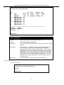
DES-6500:4#show ports 1:1 description
Command: show ports 1:1 description
Port
Port
Settings
Connection
Address
State
Speed/Duplex/FlowCtrl Speed/Duplex/FlowCtrl Learning
-----------------------------------------------------------1:1
Enabled Auto/Enabled
Link Down
Enabled
Description: Accounting
CTRL+C ESC q Quit SPACE n Next Page p Previous Page r Refresh
27
xStack DES-6500 Modular Layer 3 Chassis Ethernet Switch CLI Manual
6
P ORT S ECURITY C OMMANDS
The port security commands in the Command Line Interface (CLI) are listed (along with the appropriate parameters) in the
following table.
Command
Parameters
config port_security ports
[<portlist> | all] {admin_state [enabled | disabled] |
max_learning_addr <max_lock_no 0-64> |
lock_address_mode [Permanent | DeleteOnTimeout |
DeleteOnReset]}
show port_security
{ports <portlist>}
delete
port_security_entry_vlan_name
<vlan_name 32> port <port> mac_address <macaddr>
Each command is listed, in detail, in the following sections.
config port_security ports
Purpose
Used to configure port security settings.
Syntax
[<portlist> | all] {admin_state [enabled | disabled] |
max_learning_addr <max_lock_no 0-64> |
lock_address_mode [Permanent | DeleteOnTimeout |
DeleteOnReset]}
Description
This command allows for the configuration of the port security
feature. Only the ports listed in the <portlist> are effected.
Parameters
<portlist> − Specifies a range of ports to be displayed. The port
list is specified by listing the lowest slot number and the beginning
port number on that slot, separated by a colon. Then the highest
slot number, and the highest port number of the range (also
separated by a colon) are specified. The beginning and end of the
port list range are separated by a dash. For example, 1:3 specifies
slot number 1, port 3. 2:4 specifies slot number 2, port 4. 1:3-2:4
specifies all of the ports between slot 1, port 3 and slot 2, port 4 −
in numerical order.
all − Configure port security for all ports on the Switch.
admin_state [enabled | disabled] – Enable or disable port security
for the listed ports.
max_learning_addr <max_lock_no 0-64> - Use this to limit the
number of MAC addresses dynamically listed in the FDB for the
ports.
lock_address_mode [Permanent | DeleteOnTimeout |
DeleteOnReset] – Indicates the method of locking addresses. The
user has three choices:
Permanent – The locked addresses will not age out after
the aging timer expires.
DeleteOnTimeout – The locked addresses will age out
after the aging timer expires.
DeleteOnReset – The locked addresses will not age out
until the Switch has been reset.
Restrictions
Only administrator-level users can issue this command.
28
xStack DES-6500 Modular Layer 3 Chassis Ethernet Switch CLI Manual
Example usage:
To configure the port security:
DES-6500:4#config port_security ports 5:1-5:5 admin_state enabled
max_learning_addr 5 lock_address_mode DeleteOnReset
Command: config port_security ports 5:1-5:5 admin_state enabled
max_learning_addr 5 lock_address_mode DeleteOnReset
Success
DES-6500:4#
show port_security
Purpose
Used to display the current port security configuration.
Syntax
show port_security {ports <portlist>}
Description
This command is used to display port security information of the
Switch ports. The information displayed includes port security admin
state, maximum number of learning address and lock mode.
Parameters
ports <portlist> − Specifies a range of ports to be displayed. The
port list is specified by listing the lowest slot number and the
beginning port number on that switch, separated by a colon. Then the
highest slot number, and the highest port number of the range (also
separated by a colon) are specified. The beginning and end of the
port list range are separated by a dash. For example, 1:3 specifies
slot number 1, port 3. 2:4 specifies slot number 2, port 4. 1:3-2:4
specifies all of the ports between slot 1, port 3 and slot 2, port 4 − in
numerical order.
Restrictions
None.
Example usage:
To display the port security configuration:
DES-6500:4#show port_security ports 1:1-1:10
Command: show port_security ports 1:1-1:10
Port#
---1:1
1:2
1:3
1:4
1:5
1:6
1:7
1:8
1:9
1:10
Admin State
----------Disabled
Disabled
Disabled
Disabled
Disabled
Disabled
Enabled
Disabled
Disabled
Disabled
Max. Learning Addr.
------------------1
1
1
1
1
1
10
1
1
1
DES-6500:4#
29
Lock Address Mode
----------------DeleteOnReset
DeleteOnReset
DeleteOnReset
DeleteOnReset
DeleteOnReset
DeleteOnReset
DeleteOnReset
DeleteOnReset
DeleteOnReset
DeleteOnReset
xStack DES-6500 Modular Layer 3 Chassis Ethernet Switch CLI Manual
delete port_security_entry_vlan_name
Purpose
Used to delete an entry from the Switch’s port security settings.
Syntax
delete port_security_entry_vlan_name <vlan_name 32> port
<port> mac_address <macaddr>
Description
This command is used to remove an entry from the port security
entries learned by the Switch and entered into the forwarding
database.
Parameters
<vlan_name 32> - Enter the corresponding VLAN of the entry to
delete.
port <port> - Enter the corresponding port of the entry to delete. The
port is specified by listing the lowest slot number and the beginning
port number on that slot, separated by a colon. For example, 1:3
specifies switch number 1, port 3. 2:4 specifies switch number 2,
port 4.
mac_address <macaddr> - Enter the corresponding MAC address of
the entry to delete.
Restrictions
Only administrator-level users can issue this command.
Example usage:
To delete an entry from the port security list:
DES-6500:4#delete port_security_entry_vlan_name default port
1:1 mac_address 00-0C-6E-73-2B-C9
Command: delete port_security_entry_vlan_name default port
1:1 mac_address 00-0C-6E-73-2B-C9
Success
DES-6500:4#
30
xStack DES-6500 Modular Layer 3 Chassis Ethernet Switch CLI Manual
7
N ETWORK M ANAGEMENT (SNMP) C OMMANDS
The network management commands in the Command Line Interface (CLI) are listed (along with the appropriate parameters) in
the following table.
The xStack DES-6500 support the Simple Network Management Protocol (SNMP) versions 1, 2c, and 3. You can specify which
version of the SNMP you want to use to monitor and control the Switch. The three versions of SNMP vary in the level of
security provided between the management station and the network device. The following table lists the security features of the
three SNMP versions:
SNMP Version
Authentication Method
Description
v1
Community String
Community String is used for authentication − NoAuthNoPriv
v2c
Community String
Community String is used for authentication − NoAuthNoPriv
v3
Username
Username is used for authentication − NoAuthNoPriv
v3
MD5 or SHA
Authentication is based on the HMAC-MD5 or HMAC-SHA
algorithms − AuthNoPriv
v3
MD5 DES or SHA DES
Authentication is based on the HMAC-MD5 or HMAC-SHA
algorithms − AuthPriv.
DES 56-bit encryption is added based on the CBC-DES
(DES-56) standard
Each command is listed, in detail, in the following sections.
Command
Parameters
create snmp user
create snmp user <SNMP_name 32> <groupname 32>
{encrypted [by_password auth [md5 <auth_password 8-16> | sha
<auth_password 8-20>] priv [none | des <priv_password 8-16>] |
by_key auth [md5 <auth_key 32-32> | sha <auth_key 40-40>]
priv [none | des <priv_key 32-32>]]}
delete snmp user
<SNMP_name 32>
show snmp user
create snmp view
<view_name 32> <oid> view_type [included | excluded]
delete snmp view
<view_name 32> [all | oid]
show snmp view
<view_name 32>
create snmp community
<community_string 32> view <view_name 32> [read_only |
read_write]
delete snmp community
<community_string 32>
show snmp community
<community_string 32>
config snmp engineID
<snmp_engineID>
show snmp engineID
create snmp group
<groupname 32> {v1 | v2c | v3 [noauth_nopriv | auth_nopriv |
auth priv]} {read view <view name 32> | write view
31
xStack DES-6500 Modular Layer 3 Chassis Ethernet Switch CLI Manual
Command
Parameters
<view_name 32> | notify_view <view_name 32>}
delete snmp group
<groupname 32>
show snmp groups
create snmp host
<ipaddr> {v1 |v2c | v3 [noauth_nopriv | auth_nopriv | auth_priv]}
<auth_string 32>
delete snmp host
<ipaddr> <auth_string 32>
show snmp host
<ipaddr>
create trusted_host
<ipaddr>
delete trusted_host
<ipaddr>
show trusted_host
<ipaddr>
enable snmp traps
enable snmp
authenticate_traps
show snmp traps
disable snmp traps
disable snmp
authenticate_traps
config snmp system
contact
<sw_contact>
config snmp system
location
<sw_location>
config snmp system
name
<sw_name>
enable rmon
disable rmon
Each command is listed, in detail, in the following sections.
create snmp user
Purpose
Used to create a new SNMP user and adds the user to an SNMP
group that is also created by this command.
Syntax
create snmp user <SNMP_name 32> <groupname 32>
{encrypted [by_password auth [md5 <auth_password 8-16> |
sha <auth_password 8-20>] priv [none | des <priv_password 816>] | by_key auth [md5 <auth_key 32-32> | sha <auth_key 4040>] priv [none | des <priv_key 32-32>]]}
Description
The create snmp user command creates a new SNMP user and
adds the user to an SNMP group that is also created by this
command. SNMP ensures:
Message integrity − Ensures that packets have not been tampered
with during transit.
Authentication − Determines if an SNMP message is from a valid
source.
32
xStack DES-6500 Modular Layer 3 Chassis Ethernet Switch CLI Manual
create snmp user
Encryption − Scrambles the contents of messages to prevent it from
being viewed by an unauthorized source.
Parameters
<username 32> − An alphanumeric name of up to 32 characters
that will identify the new SNMP user.
<groupname 32> − An alphanumeric name of up to 32 characters
that will identify the SNMP group with which the new SNMP user
will be associated.
encrypted – Allows the user to choose a type of authorization for
authentication using SNMP. The user may choose:
•
by_password – Requires the SNMP user to enter a
password for authentication and privacy. The password is
defined by specifying the auth_password below. This
method is recommended.
•
by_key – Requires the SNMP user to enter a encryption
key for authentication and privacy. The key is defined by
specifying the key in hex form below. This method is not
recommended.
auth - The user may also choose the type of authentication
algorithms used to authenticate the snmp user. The choices are:
•
md5 − Specifies that the HMAC-MD5-96 authentication
level will be used. md5 may be utilized by entering one of
the following:
<auth password 8-16> - An alphanumeric sting of
between 8 and 16 characters that will be used to
authorize the agent to receive packets for the host.
<auth_key 32-32> - Enter an alphanumeric sting of
exactly 32 characters, in hex form, to define the key that
will be used to authorize the agent to receive packets for
the host.
•
sha − Specifies that the HMAC-SHA-96 authentication
level will be used.
<auth password 8-20> - An alphanumeric sting of
between 8 and 20 characters that will be used to
authorize the agent to receive packets for the host.
<auth_key 40-40> - Enter an alphanumeric sting of
exactly 40 characters, in hex form, to define the key that
will be used to authorize the agent to receive packets for
the host.
priv – Adding the priv (privacy) parameter will allow for encryption in
addition to the authentication algorithm for higher security. The user
may choose:
•
des – Adding this parameter will allow for a 56-bit
encryption to be added using the DES-56 standard using:
<priv_password 8-16> - An alphanumeric string of
between 8 and 16 characters that will be used to
encrypt the contents of messages the host sends to
33
xStack DES-6500 Modular Layer 3 Chassis Ethernet Switch CLI Manual
create snmp user
the agent.
<priv_key 32-32> - Enter an alphanumeric key string
of exactly 32 characters, in hex form, that will be
used to encrypt the contents of messages the host
sends to the agent.
•
Restrictions
none – Adding this parameter will add no encryption.
Only administrator-level users can issue this command.
Example usage:
To create an SNMP user on the Switch:
DES-6500:4#create snmp user dlink default encrypted
by_password auth md5 auth_password priv none
Command: create snmp user dlink default encrypted
by_password auth md5 auth_password priv none
Success.
DES-6500:4#
delete snmp user
Purpose
Used to remove an SNMP user from an SNMP group and also to
delete the associated SNMP group.
Syntax
delete snmp user <SNMP_name 32>
Description
The delete snmp user command removes an SNMP user from
its SNMP group and then deletes the associated SNMP group.
Parameters
<SNMP_name 32> − An alphanumeric string of up to 32
characters that identifies the SNMP user that will be deleted.
Restrictions
Only administrator-level users can issue this command.
Example usage:
To delete a previously entered SNMP user on the Switch:
DES-6500:4#delete snmp user dlink
Command: delete snmp user dlink
Success.
DES-6500:4#
show snmp user
34
xStack DES-6500 Modular Layer 3 Chassis Ethernet Switch CLI Manual
show snmp user
Purpose
Used to display information about each SNMP username in the
SNMP group username table.
Syntax
show snmp user
Description
The show snmp user command displays information about each
SNMP username in the SNMP group username table.
Parameters
None.
Restrictions
Only administrator-level users can issue this command.
Example usage:
To display the SNMP users currently configured on the Switch:
DES-6500:4#show snmp user
Command: show snmp user
Username
--------------initial
Group Name
-------------------initial
VerAuthPriv
--------------------V3 None None
Total Entries: 1
DES-6500:4#
create snmp view
Purpose
Used to assign views to community strings to limit which MIB
objects and SNMP manager can access.
Syntax
create snmp view <view_name 32> <oid> view_type [included |
excluded]
Description
The create snmp view command assigns views to community
strings to limit which MIB objects an SNMP manager can access.
Parameters
<view_name 32> − An alphanumeric string of up to 32 characters
that identifies the SNMP view that will be created.
<oid> − The object ID that identifies an object tree (MIB tree) that
will be included or excluded from access by an SNMP manager.
included − Include this object in the list of objects that an SNMP
manager can access.
excluded − Exclude this object from the list of objects that an SNMP
manager can access.
Restrictions
Only administrator-level users can issue this command.
Example usage:
To create an SNMP view:
35
xStack DES-6500 Modular Layer 3 Chassis Ethernet Switch CLI Manual
DES-6500:4#create snmp view dlinkview 1.3.6 view_type included
Command: create snmp view dlinkview 1.3.6 view_type included
Success.
DES-6500:4#
delete snmp view
Purpose
Used to remove an SNMP view entry previously created on the
Switch.
Syntax
delete snmp view <view_name 32> [all | <oid>]
Description
The delete snmp view command is used to remove an SNMP
view previously created on the Switch.
Parameters
<view_name 32> − An alphanumeric string of up to 32 characters
that identifies the SNMP view to be deleted.
all − Specifies that all of the SNMP views on the Switch will be
deleted.
<oid> − The object ID that identifies an object tree (MIB tree) that
will be deleted from the Switch.
Restrictions
Only administrator-level users can issue this command.
Example usage:
To delete a previously configured SNMP view from the Switch:
DES-6500:4#delete snmp view dlinkview all
Command: delete snmp view dlinkview all
Success.
DES-6500:4#
show snmp view
Purpose
Used to display an SNMP view previously created on the Switch.
Syntax
show snmp view {<view_name 32>}
Description
The show snmp view command displays an SNMP view
previously created on the Switch.
Parameters
<view_name 32> − An alphanumeric string of up to 32 characters
that identifies the SNMP view that will be displayed.
Restrictions
None.
Example usage:
To display SNMP view configuration:
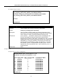
DES-6500:4#show snmp view
36
xStack DES-6500 Modular Layer 3 Chassis Ethernet Switch CLI Manual
Command: show snmp view
Vacm View Table Settings
View Name
-------------------ReadView
WriteView
NotifyView
restricted
restricted
restricted
restricted
restricted
CommunityView
CommunityView
CommunityView
Subtree
------------------------1
1
1.3.6
1.3.6.1.2.1.1
1.3.6.1.2.1.11
1.3.6.1.6.3.10.2.1
1.3.6.1.6.3.11.2.1
1.3.6.1.6.3.15.1.1
1
1.3.6.1.6.3
1.3.6.1.6.3.1
View Type
---------Included
Included
Included
Included
Included
Included
Included
Included
Included
Excluded
Included
Total Entries: 11
DES-6500:4#
create snmp community
Purpose
Used to create an SNMP community string to define the relationship
between the SNMP manager and an agent. The community string acts
like a password to permit access to the agent on the Switch. One or
more of the following characteristics can be associated with the
community string:
An Access List of IP addresses of SNMP managers that are permitted to
use the community string to gain access to the Switch’s SNMP agent.
An MIB view that defines the subset of all MIB objects that will be
accessible to the SNMP community.
Read-write or read-only level permission for the MIB objects accessible
to the SNMP community.
Syntax
create snmp community <community_string 32> view <view_name
32> [read_only | read_write]
Description
The create snmp community command is used to create an SNMP
community string and to assign access-limiting characteristics to this
community string.
Parameters
<community_string 32> − An alphanumeric string of up to 32 characters
that is used to identify members of an SNMP community. This string is
used like a password to give remote SNMP managers access to MIB
objects in the Switch’s SNMP agent.
view <view_name 32> − An alphanumeric string of up to 32 characters
that is used to identify the group of MIB objects that a remote SNMP
manager is allowed to access on the Switch.
read_only − Specifies that SNMP community members using the
community string created with this command can only read the contents
of the MIBs on the Switch.
read_write − Specifies that SNMP community members using the
community string created with this command can read from and write to
the contents of the MIBs on the Switch.
Restrictions
Only administrator-level users can issue this command.
37
xStack DES-6500 Modular Layer 3 Chassis Ethernet Switch CLI Manual
Example usage:
To create the SNMP community string “dlink:”
DES-6500:4#create snmp community dlink view ReadView read_write
Command: create snmp community dlink view ReadView read_write
Success.
DES-6500:4#
delete snmp community
Purpose
Used to remove a specific SNMP community string from the
Switch.
Syntax
delete snmp community <community_string 32>
Description
The delete snmp community command is used to remove a
previously defined SNMP community string from the Switch.
Parameters
<community_string 32> − An alphanumeric string of up to 32
characters that is used to identify members of an SNMP
community. This string is used like a password to give remote
SNMP managers access to MIB objects in the Switch’s SNMP
agent.
Restrictions
Only administrator-level users can issue this command.
Example usage:
To delete the SNMP community string “dlink:”
DES-6500:4#delete snmp community dlink
Command: delete snmp community dlink
Success.
DES-6500:4#
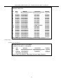
show snmp community
Purpose
Used to display SNMP community strings configured on the
Switch.
Syntax
show snmp community {<community_string 32>}
Description
The show snmp community command is used to display SNMP
community strings that are configured on the Switch.
Parameters
<community_string 32> − An alphanumeric string of up to 32
characters that is used to identify members of an SNMP
community. This string is used like a password to give remote
SNMP managers access to MIB objects in the Switch’s SNMP
agent.
Restrictions
None.
38
xStack DES-6500 Modular Layer 3 Chassis Ethernet Switch CLI Manual
Example usage:
To display the currently entered SNMP community strings:
DES-6500:4#show snmp community
Command: show snmp community
SNMP Community Table
Community Name
View Name
------------------------------ -----------------------------dlink
ReadView
private
CommunityView
public
CommunityView
Access Right
-----------read_write
read_write
read_only
Total Entries: 3
DES-6500:4#
config snmp engineID
Purpose
Used to configure a name for the SNMP engine on the Switch.
Syntax
config snmp engineID <snmp_engineID>
Description
The config snmp engineID command configures a name for the
SNMP engine on the Switch.
Parameters
<snmp_engineID> − An alphanumeric string that will be used to
identify the SNMP engine on the Switch.
Restrictions
Only administrator-level users can issue this command.
Example usage:
To give the SNMP agent on the Switch the name “0035636666”
DES-6500:4#config snmp engineID 0035636666
Command: config snmp engineID 0035636666
Success.
DES-6500:4#
show snmp engineID
Purpose
Used to display the identification of the SNMP engine on the
Switch.
Syntax
show snmp engineID
Description
The show snmp engineID command displays the identification of
the SNMP engine on the Switch.
Parameters
None.
Restrictions
None.
Example usage:
39
xStack DES-6500 Modular Layer 3 Chassis Ethernet Switch CLI Manual
To display the current name of the SNMP engine on the Switch:
DES-6500:4#show snmp engineID
Command: show snmp engineID
SNMP Engine ID : 0035636666
DES-6500:4#
create snmp group
Purpose
Used to create a new SNMP group, or a table that maps SNMP
users to SNMP views.
Syntax
create snmp group <groupname 32> [v1 | v2c | v3
[noauth_nopriv | auth_nopriv | auth_priv]] {read_view
<view_name 32> | write_view <view_name 32> | notify_view
<view_name 32>}
Description
The create snmp group command creates a new SNMP group,
or a table that maps SNMP users to SNMP views.
Parameters
<groupname 32> − An alphanumeric name of up to 32 characters
that will identify the SNMP group the new SNMP user will be
associated with.
v1 – Specifies that SNMP version 1 will be used. The Simple
Network Management Protocol (SNMP), version 1, is a network
management protocol that provides a means to monitor and
control network devices.
v2c – Specifies that SNMP version 2c will be used. The SNMP
v2c supports both centralized and distributed network
management strategies. It includes improvements in the Structure
of Management Information (SMI) and adds some security
features.
v3 – Specifies that the SNMP version 3 will be used. SNMP v3
provides secure access to devices through a combination of
authentication and encrypting packets over the network. SNMP v3
adds:
Message integrity − Ensures that packets have not been
tampered with during transit.
Authentication − Determines if an SNMP message is from
a valid source.
Encryption − Scrambles the contents of messages to
prevent it being viewed by an unauthorized source.
noauth_nopriv − Specifies that there will be no authorization and
no encryption of packets sent between the Switch and a remote
SNMP manager.
auth_nopriv − Specifies that authorization will be required, but
there will be no encryption of packets sent between the Switch
and a remote SNMP manager.
auth_priv − Specifies that authorization will be required, and that
packets sent between the Switch and a remote SNMP manger will
40
xStack DES-6500 Modular Layer 3 Chassis Ethernet Switch CLI Manual
create snmp group
be encrypted.
read_view – Specifies that the SNMP group being created can
request SNMP messages.
write_view – Specifies that the SNMP group being created has
write privileges.
<view_name 32> − An alphanumeric string of up to 32 characters
that is used to identify the group of MIB objects that a remote
SNMP manager is allowed to access on the Switch.
notify_view − Specifies that the SNMP group being created can
receive SNMP trap messages generated by the Switch’s SNMP
agent.
Restrictions
Only administrator-level users can issue this command.
Example usage:
To create an SNMP group named “sg1:”
DES-6500:4#create snmp group sg1 v3 noauth_nopriv read_view v1
write_view v1 notify_view v1
Command: create snmp group sg1 v3 noauth_nopriv read_view v1
write_view v1 notify_view v1
Success.
DES-6500:4#
delete snmp group
Purpose
Used to remove an SNMP group from the Switch.
Syntax
delete snmp group <groupname 32>
Description
The delete snmp group command is used to remove an SNMP
group from the Switch.
Parameters
<groupname 32> − An alphanumeric name of up to 32 characters
that will identify the SNMP group to be deleted.
Restrictions
Only administrator-level users can issue this command.
Example usage:
To delete the SNMP group named “sg1”.
DES-6500:4#delete snmp group sg1
Command: delete snmp group sg1
Success.
DES-6500:4#
41
xStack DES-6500 Modular Layer 3 Chassis Ethernet Switch CLI Manual
show snmp groups
Purpose
Used to display the group-names of SNMP groups currently
configured on the Switch. The security model, level, and status of
each group are also displayed.
Syntax
show snmp groups
Description
The show snmp groups command displays the group-names of
SNMP groups currently configured on the Switch. The security
model, level, and status of each group are also displayed.
Parameters
None.
Restrictions
None.
Example usage:
To display the currently configured SNMP groups on the Switch:
DES-6500:4#show snmp groups
Command: show snmp groups
Vacm Access Table Settings
Group Name
ReadView Name
WriteView Name
Notify View Name
Security Model
Security Level
: Group3
: ReadView
: WriteView
: NotifyView
: SNMPv3
: NoAuthNoPriv
Group Name
ReadView Name
WriteView Name
Notify View Name
Security Model
Security Level
: Group4
: ReadView
: WriteView
: NotifyView
: SNMPv3
: authNoPriv
Group Name
ReadView Name
WriteView Name
Notify View Name
Security Model
Security Level
: Group5
: ReadView
: WriteView
: NotifyView
: SNMPv3
: authNoPriv
Group Name
ReadView Name
WriteView Name
Notify View Name
Security Model
Security Level
: Group6
: ReadView
: WriteView
: NotifyView
: SNMPv3
: authPriv
Group Name
ReadView Name
WriteView Name
Notify View Name
Security Model
Security Level
: Group7
: ReadView
: WriteView
: NotifyView
: SNMPv3
: authPriv
Group
: initial
Name
42
xStack DES-6500 Modular Layer 3 Chassis Ethernet Switch CLI Manual
ReadView Name
WriteView Name
Notify View Name
Security Model
Security Level
: restricted
:
: restricted
: SNMPv3
: NoAuthNoPriv
Group Name
ReadView Name
WriteView Name
Notify View Name
Security Model
Security Level
: ReadGroup
: CommunityView
:
: CommunityView
: SNMPv1
: NoAuthNoPriv
Group Name
ReadView Name
WriteView Name
Notify View Name
Security Model
Security Level
: ReadGroup
: CommunityView
:
: CommunityView
: SNMPv2
: NoAuthNoPriv
Group Name
ReadView Name
WriteView Name
Notify View Name
Security Model
Security Level
: WriteGroup
: CommunityView
: CommunityView
: CommunityView
: SNMPv1
: NoAuthNoPriv
Group Name
ReadView Name
WriteView Name
Notify View Name
Security Model
Security Level
: WriteGroup
: CommunityView
: CommunityView
: CommunityView
: SNMPv2
: NoAuthNoPriv
Total Entries: 10
DES-6500:4#
create snmp host
Purpose
Used to create a recipient of SNMP traps generated by the
Switch’s SNMP agent.
Syntax
create snmp host <ipaddr> [v1 | v2c | v3 [noauth_nopriv |
auth_nopriv | auth_priv]] <auth_string 32>
Description
The create snmp host command creates a recipient of SNMP
traps generated by the Switch’s SNMP agent.
Parameters
<ipaddr> − The IP address of the remote management station
that will serve as the SNMP host for the Switch.
v1 – Specifies that SNMP version 1 will be used. The Simple
Network Management Protocol (SNMP), version 1, is a network
management protocol that provides a means to monitor and
control network devices.
v2c – Specifies that SNMP version 2c will be used. The SNMP
v2c supports both centralized and distributed network
management strategies. It includes improvements in the Structure
43
xStack DES-6500 Modular Layer 3 Chassis Ethernet Switch CLI Manual
create snmp host
of Management Information (SMI) and adds some security
features.
v3 – Specifies that the SNMP version 3 will be used. SNMP v3
provides secure access to devices through a combination of
authentication and encrypting packets over the network. SNMP
v3 adds:
Message integrity − Ensures that packets have not been
tampered with during transit.
Authentication − Determines if an SNMP message is from
a valid source.
Encryption − Scrambles the contents of messages to
prevent it being viewed by an unauthorized source.
noauth_nopriv − Specifies that there will be no authorization and
no encryption of packets sent between the Switch and a remote
SNMP manager.
auth_nopriv − Specifies that authorization will be required, but
there will be no encryption of packets sent between the Switch
and a remote SNMP manager.
auth_priv − Specifies that authorization will be required, and that
packets sent between the Switch and a remote SNMP manger
will be encrypted.
<auth_sting 32> − An alphanumeric string used to authorize a
remote SNMP manager to access the Switch’s SNMP agent.
Restrictions
Only administrator-level users can issue this command.
Example usage:
To create an SNMP host to receive SNMP messages:
DES-6500:4#create snmp host 10.48.74.100 v3 auth_priv public
Command: create snmp host 10.48.74.100 v3 auth_priv public
Success.
DES-6500:4#
delete snmp host
Purpose
Used to remove a recipient of SNMP traps generated by the
Switch’s SNMP agent.
Syntax
delete snmp host <ipaddr> <auth_string 32>
Description
The delete snmp host command deletes a recipient of SNMP
traps generated by the Switch’s SNMP agent.
Parameters
<ipaddr> − The IP address of a remote SNMP manager that will
receive SNMP traps generated by the Switch’s SNMP agent.
<auth_sting 32> − The alphanumeric string created to authorize a
remote SNMP manager to access the Switch’s SNMP agent.
Restrictions
Only administrator-level users can issue this command.
44
xStack DES-6500 Modular Layer 3 Chassis Ethernet Switch CLI Manual
Example usage:
To delete an SNMP host entry:
DES-6500:4#delete snmp host 10.48.74.100 public
Command: delete snmp host 10.48.74.100 public
Success.
DES-6500:4#
show snmp host
Purpose
Used to display the recipient of SNMP traps generated by the
Switch’s SNMP agent.
Syntax
show snmp host {<ipaddr>}
Description
The show snmp host command is used to display the IP
addresses and configuration information of remote SNMP
managers that are designated as recipients of SNMP traps that
are generated by the Switch’s SNMP agent.
Parameters
<ipaddr> − The IP address of a remote SNMP manager that will
receive SNMP traps generated by the Switch’s SNMP agent.
Restrictions
None.
Example usage:
To display the currently configured SNMP hosts on the Switch:
DES-6500:4#show snmp host
Command: show snmp host
SNMP Host Table
Host IP Address
--------------10.48.76.23
10.48.74.100
SNMP Version
--------------------V2c
V3 authpriv
Community Name/SNMPv3 User Name
-----------------------------private
public
Total Entries: 2
DES-6500:4#
create trusted_host
Purpose
Used to create the trusted host.
Syntax
create trusted_host <ipaddr>
Description
The create trusted_host command creates the trusted host.
The Switch allows specification up to four IP addresses that are
allowed to manage the Switch via in-band SNMP or TELNET
based management software. These IP addresses must be
members of the Management VLAN. If no IP addresses are
specified, then there is nothing to prevent any IP address from
accessing the Switch, provided the user knows the Username
and Password.
45
xStack DES-6500 Modular Layer 3 Chassis Ethernet Switch CLI Manual
create trusted_host
Parameters
<ipaddr> − The IP address of the trusted host.
Restrictions
Only administrator-level users can issue this command.
Example usage:
To create the trusted host:
DES-6500:4#create trusted_host 10.48.74.121
Command: create trusted_host 10.48.74.121
Success.
DES-6500:4#
show trusted_host
Purpose
Used to display a list of trusted hosts entered on the Switch using
the create trusted_host command above.
Syntax
show trusted_host
Description
This command is used to display a list of trusted hosts entered on
the Switch using the create trusted_host command above.
Parameters
None.
Restrictions
None.
Example Usage:
To display the list of trust hosts:
DES-6500:4#show trusted_host
Command: show trusted_host
Management Stations
IP Address
-------------------10.53.13.94
Total Entries: 1
DES-6500:4#
delete trusted_host
Purpose
Used to delete a trusted host entry made using the create
trusted_host command above.
Syntax
delete trusted _host <ipaddr>
Description
This command is used to delete a trusted host entry made using
the create trusted_host command above.
Parameters
<ipaddr> − The IP address of the trusted host.
Restrictions
Only administrator-level users can issue this command.
46
xStack DES-6500 Modular Layer 3 Chassis Ethernet Switch CLI Manual
Example Usage:
To delete a trusted host with an IP address 10.48.74.121:
DES-6500:4#delete trusted_host 10.48.74.121
Command: delete trusted_host 10.48.74.121
Success.
DES-6500:4#
enable snmp traps
Purpose
Used to enable SNMP trap support.
Syntax
enable snmp traps
Description
The enable snmp traps command is used to enable SNMP trap
support on the Switch.
Parameters
None.
Restrictions
Only administrator-level users can issue this command.
Example usage:
To enable SNMP trap support on the Switch:
DES-6500:4#enable snmp traps
Command: enable snmp traps
Success.
DES-6500:4#
enable snmp authenticate_traps
Purpose
Used to enable SNMP authentication trap support.
Syntax
enable snmp authenticate_traps
Description
This command is used to enable SNMP authentication trap
support on the Switch.
Parameters
None.
Restrictions
Only administrator-level users can issue this command.
Example Usage:
To turn on SNMP authentication trap support:
DES-6500:4#enable snmp authenticate_traps
Command: enable snmp authenticate_traps
Success.
DES-6500:4#
47
xStack DES-6500 Modular Layer 3 Chassis Ethernet Switch CLI Manual
show snmp traps
Purpose
Used to show SNMP trap support on the Switch .
Syntax
show snmp traps
Description
This command is used to view the SNMP trap support status
currently configured on the Switch.
Parameters
None.
Restrictions
Only administrator-level users can issue this command.
Example usage:
To view the current SNMP trap support:
DES-6500:4#show snmp traps
Command: show snmp traps
SNMP Traps
: Enabled
Authenticate Traps : Enabled
DES-6500:4#
disable snmp traps
Purpose
Used to disable SNMP trap support on the Switch.
Syntax
disable snmp traps
Description
This command is used to disable SNMP trap support on the
Switch.
Parameters
None.
Restrictions
Only administrator-level users can issue this command.
Example Usage:
To prevent SNMP traps from being sent from the Switch:
DES-6500:4#disable snmp traps
Command: disable snmp traps
Success.
DES-6500:4#
disable snmp authenticate_traps
Purpose
Used to disable SNMP authentication trap support.
Syntax
disable snmp authenticate_traps
Description
This command is used to disable SNMP authentication support on
the Switch.
Parameters
None.
Restrictions
Only administrator-level users can issue this command.
48
xStack DES-6500 Modular Layer 3 Chassis Ethernet Switch CLI Manual
Example Usage:
To disable the SNMP authentication trap support:
DES-6500:4#disable snmp authenticate_traps
Command: disable snmp authenticate_traps
Success.
DES-6500:4#
config snmp system_contact
Purpose
Used to enter the name of a contact person who is responsible for
the Switch.
Syntax
config snmp system_contact {<sw_contact>}
Description
The config snmp system_contact command is used to enter the
name and/or other information to identify a contact person who is
responsible for the Switch. A maximum of 255 character can be
used.
Parameters
<sw_contact> - A maximum of 255 characters is allowed. A NULL
string is accepted if there is no contact.
Restrictions
Only administrator-level users can issue this command.
Example usage:
To configure the Switch contact to “M I S D e p a r t m e n t I I ”:
DES-6500:4#config snmp system_contact MIS Department II
Command: config snmp system_contact MIS Department II
Success.
DES-6500:4#
config snmp system_location
Purpose
Used to enter a description of the location of the Switch.
Syntax
config snmp system_location {<sw_location>}
Description
The config snmp system_location command is used to enter a
description of the location of the Switch. A maximum of 255
characters can be used.
Parameters
<sw_location> - A maximum of 255 characters is allowed. A NULL
string is accepted if there is no location desired.
Restrictions
Only administrator-level users can issue this command.
Example usage:
49
xStack DES-6500 Modular Layer 3 Chassis Ethernet Switch CLI Manual
To configure the Switch location for “H Q 5 F ”:
DES-6500:4#config snmp system_location HQ 5F
Command: config snmp system_location HQ 5F
Success.
DES-6500:4#
config snmp system_name
Purpose
Used to configure the name for the Switch.
Syntax
config snmp system_name {<sw_name>}
Description
The config snmp system_name command configures the name
of the Switch.
Parameters
<sw_name> - A maximum of 255 characters is allowed. A NULL
string is accepted if no name is desired.
Restrictions
Only administrator-level users can issue this command.
Example usage:
To configure the Switch name for “DES-6500 Chassis Switch ”:
DES-6500:4#config snmp system_name DES-6500 Chassis Switch
Command: config snmp system_name DES-6500 Chassis Switch
Success.
DES-6500:4#
enable rmon
Purpose
Used to enable RMON on the Switch.
Syntax
enable rmon
Description
This command is used, in conjunction with the disable rmon
command below, to enable and disable remote monitoring
(RMON) on the Switch.
Parameters
None.
Restrictions
Only administrator-level users can issue this command.
Example Usage:
To enable RMON:
50
xStack DES-6500 Modular Layer 3 Chassis Ethernet Switch CLI Manual
DES-6500:4#enable rmon
Command: enable rmon
Success.
DES-6500:4#
disable rmon
Purpose
Used to disable RMON on the Switch.
Syntax
disable rmon
Description
This command is used, in conjunction with the enable rmon
command above, to enable and disable remote monitoring
(RMON) on the Switch.
Parameters
None.
Restrictions
Only administrator-level users can issue this command.
Example Usage:
To disable RMON:
DES-6500:4#disable rmon
Command: disable rmon
Success.
DES-6500:4#
51
xStack DES-6500 Modular Layer 3 Chassis Ethernet Switch CLI Manual
8
S WITCH U TILITY C OMMANDS
The switch utility commands in the Command Line Interface (CLI) are listed (along with the appropriate parameters) in the
following table.
Command
Parameters
download
[firmware_fromTFTP <ipaddr> <path_filename 64> unit
[all_line_card | cpu | <unitid 1-8>]} | cfg_fromTFTP <ipaddr>
<path_filename 64> {increment}
upload
[cfg_toTFTP | log_toTFTP] <ipaddr> <path_filename 64>
ping
<ipaddr> {times <value 1-255>} {timeout <sec 1-99>}
traceroute
<ipaddr> {ttl <value 1-60> | port <value 30000-64900> | timeout
<sec 1-65535> | probe <value <1-9>
enable autoconfig
disable autoconfig
show autoconfig
Each command is listed, in detail, in the following sections.
download
Purpose
Used to download and install new firmware or a switch
configuration file from a TFTP server or a CompactFlash memory
card.
Syntax
[firmware_fromTFTP <ipaddr> <path_filename 64> unit
[all_line_card | cpu | <unitid 1-8>]} | cfg_fromTFTP <ipaddr>
<path_filename 64> {increment}
Description
This command is used to download a new firmware or a switch
configuration file from a TFTP server or a CompactFlash memory
card.
Parameters
firmware_fromTFTP − Download and install new firmware on the
Switch from a TFTP server.
<ipaddr> − The IP address of the TFTP server. The TFTP
server must be on the same IP subnet as the Switch.
<path_filename 64> − The DOS path and filename of the
firmware or switch configuration file on the TFTP server. For
example, C:\3226S.had.
unit [all_line_card | cpu | <unitid 1-8>] − all specifies all
installed modules except the CPU module, cpu specifies the
chassis’ CPU module and <unitid> is the unit ID of a specific
installed module that will receive the download.
cfg_fromTFTP - Download a switch configuration file from a TFTP
server.
<ipaddr> − The IP address of the TFTP server. The TFTP
server must be on the same IP subnet as the Switch.
<path_filename 64> − The DOS path and filename of the
firmware or switch configuration file on the TFTP server or
CompactFlash card. For example, C:\3226S.had.
52
xStack DES-6500 Modular Layer 3 Chassis Ethernet Switch CLI Manual
download
increment − Allows the download of a partial switch
configuration file. This allows a file to be downloaded that will
change only the Switch parameters explicitly stated in the
configuration file. All other switch parameters will remain
unchanged.
Restrictions
The TFTP server must be on the same IP subnet as the Switch.
Only administrator-level users can issue this command.
Example usage:
To download a configuration file:
DES-6500:4#download cfg_to TFTP 10.48.74.121 c:\cfg\setting.txt
Command: download cfg_to TFTP 10.48.74.121 c:\cfg\setting.txt
Connecting to server................... Done.
Download configuration............. Done.
DES-6500:4#
Due to a backward compatability issue, when a user upgrades to R3 firmware (3.00-B29),
all settings previously configured for any ACL function (CPU ACL included) on the Switch
will be lost. We recommend that the user save a configuration file of current settings before
upgrading to R3 firmware.
upload
Purpose
Used to upload the current switch settings or the switch history log
to a TFTP server or a CompactFlash memory card.
Syntax
upload [cfg_toTFTP | log_toTFTP] <ipaddr> <path_filename 64>
Description
This command is used to upload either the Switch’s current settings,
the Switch’s history log or firmware to a TFTP server or a
CompactFlash memory card.
Parameters
cfg_toTFTP − Specifies that the Switch’s current settings will be
uploaded to the TFTP server.
log_toTFTP − Specifies that the Switch’s current log will be
uploaded to the TFTP server.
<ipaddr> − The IP address of the TFTP server. The TFTP
server must be on the same IP subnet as the Switch.
<path_filename 64> − Specifies the location of the Switch
configuration file on the TFTP server. This file will be replaced
by the uploaded file from the Switch.
Restrictions
The TFTP server must be on the same IP subnet as the Switch.
Only administrator-level users can issue this command.
Example usage:
To upload a configuration file:
53
xStack DES-6500 Modular Layer 3 Chassis Ethernet Switch CLI Manual
DES-6500:4#upload cfg_toTFTP 10.48.74.121 c:\cfg\log.txt
Command: upload cfg_to TFTP 10.48.74.121 c:\cfg\log.txt
Connecting to server................... Done.
Upload configuration...................Done.
DES-6500:4#
ping
Purpose
Used to test the connectivity between network devices.
Syntax
ping <ipaddr> {times <value 1-255>} {timeout <sec 1-99>}
Description
The ping command sends Internet Control Message Protocol
(ICMP) echo messages to a remote IP address. The remote IP
address will then “echo” or return the message. This is used to
confirm connectivity between the Switch and the remote device.
Parameters
<ipaddr> - Specifies the IP address of the host.
times <value 1-255> - The number of individual ICMP echo
messages to be sent. The maximum value is 255. The default is 0.
timeout <sec 1-99> - Defines the time-out period while waiting for a
response from the remote device. A value of 1 to 99 seconds can
be specified. The default is 1 second.
Pinging an IP address without the times parameter will ping the
target device an infinite amount of times.
Restrictions
None.
Example usage:
To ping the IP address 10.48.74.121 four times:
DES-6500:4#ping 10.48.74.121 times 4
Command: ping 10.48.74.121
Reply from 10.48.74.121, time<10ms
Reply from 10.48.74.121, time<10ms
Reply from 10.48.74.121, time<10ms
Reply from 10.48.74.121, time<10ms
Ping statistics for 10.48.74.121
Packets: Sent =4, Received =4, Lost =0
DES-6500:4#
traceroute
Purpose
Used to trace the routed path between the Switch and a destination
endstation.
Syntax
traceroute <ipaddr> {ttl <value 1-60> | port <value 30000-64900> |
timeout <sec 1-65535> | probe <value <1-9>}
Description
The traceroute command allows you to trace a route between the Switch
and a give host on the network.
54
xStack DES-6500 Modular Layer 3 Chassis Ethernet Switch CLI Manual
traceroute
Parameters
<ipaddr> - Specifies the IP address of the host.
ttl <value 1-60> - The time to live value of the trace route request. This is
the maximum number of routers the traceroute command will cross while
seeking the network path between two devices.
port <value 30000-64900> - The port number. Must be above 1024.The
value range is from 30000 to 64900.
timeout <sec 1-65535> - Defines the time-out period while waiting for a
response from the remote device. The user may choose an entry
between 1 and 65535 seconds.
probe <value 1-9> - The probe value is the number of times the Switch
will send probe packets to the next hop on the intended traceroute path.
The default is 1.
Restrictions
None.
Example usage:
To trace the routed path between the Switch and 10.48.74.121.
DES-6500:4#traceroute 10.48.74.121 p r o b e 3
Command: traceroute 10.48.74.121 p r o b e 3
1 <10ms 10.254.254.251
2 <10ms 10.55.25.35
3 <10ms 10.22.35.1
DES-6500:4#
enable autoconfig
Purpose
Used to activate the autoconfiguration function for the Switch. This will load a
previously saved configuration file for current use.
Syntax
enable autoconfig
Description
When autoconfig is enabled on the Switch, the DHCP reply will contain a
configuration file and path name. It will then request the file from the TFTP
server specified in the reply. When autoconfig is enabled, the ipif settings will
automatically become DHCP client.
Parameters
None.
Restrictions
When autoconfig is enabled, the Switch becomes a DHCP client automatically
(same as: config ipif System dhcp). The DHCP server must have the TFTP
server IP address and configuration file name, and be configured to deliver
this information in the data field of the DHCP reply packet. The TFTP server
must be running and have the requested configuration file in its base directory
when the request is received from the Switch. Consult the DHCP server and
TFTP server software instructions for information on loading a configuration
file.
If the Switch is unable to complete the autoconfiguration process the
previously saved local configuration file present in Switch memory will be
loaded.
55
xStack DES-6500 Modular Layer 3 Chassis Ethernet Switch CLI Manual
NOTE: Dual-purpose (DHCP/TFTP) server utility software may require entry of the
configuration file name and path within the user interface. Alternatively, the DHCP
software may require creating a separate ext file with the configuration file name
and path in a specific directory on the server. Consult the documentation for the
DCHP server software if you are unsure.
When autoconfig is enabled and the Switch is rebooted, the normal login screen will appear for a few moments while the
autoconfig request (i.e. download configuration) is initiated. The console will then display the configuration parameters as they
are loaded from the configuration file specified in the DHCP or TFTP server. This is exactly the same as using a download
configuration command. After the entire Switch configuration is loaded, the Switch will automatically “logout” the server. The
configuration settings will be saved automatically and become the active configuration.
Upon booting up the autoconfig process is initiated, the console screen will appear similar to the example below. The
configuration settings will be loaded in normal order.
Example usage:
To enable autoconfiguration on the Switch:
DES-6500:4#enable autoconfig
Command: enable autoconfig
Success.
DES-6500:4#
DES-6500 Chassis Ethernet Switch
Command Line Interface
Firmware: Build 3.00-B29
Copyright(C) 2004-2007 D-Link Corporation. All rights reserved.
DES-6500:4#
DES-6500:4#
DES-6500:4#download configuration 10.41.44.44 c:\cfg\setting.txt
Command: download configuration 10.41.44.44 c:\cfg\setting.txt
Connecting to server................... Done.
Download configuration................. Done.
The very end of the autoconfig process including the logout appears like this:
DES-6500:4#disable authen_policy
Command: disable authen_policy
Success.
DES-6500:4#
DES-6500:4##------------------------------------------------------------------DES-6500:4##
End of configuration file for DES-6500
DES-6500:4#
**********
* Logout *
**********
56
xStack DES-6500 Modular Layer 3 Chassis Ethernet Switch CLI Manual
disable autoconfig
Purpose
Use this to deactivate autoconfiguration from DHCP.
Syntax
disable autoconfig
Description
This instructs the Switch not to accept autoconfiguration instruction from
the DHCP server. This does not change the IP settings of the Switch. The
ipif settings will continue as DHCP client until changed with the config ipif
command.
Parameters
None.
Restrictions
None.
Example usage:
To stop the autoconfiguration function:
DES-6500:4#disable autoconfig
Command: disable autoconfig
Success.
DES-6500:4#
NOTE: With autoconfig enabled, the Switch ipif settings now define the
Switch as a DHCP client. Use the show switch command to display the
new IP settings status.
show autoconfig
Purpose
Used to display the current autoconfig status of the Switch.
Syntax
show autoconfig
Description
This will list the current status of the autoconfiguration function.
Parameters
None.
Restrictions
None.
Example usage:
To show the autoconfig configuration set on the Switch:
DES-6500:4#show autoconfig
Command: show autoconfig
Autoconfig disabled.
Success.
DES-6500:4#
57
xStack DES-6500 Modular Layer 3 Chassis Ethernet Switch CLI Manual
9
N ETWORK M ONITORING C OMMANDS
The network monitoring commands in the Command Line Interface (CLI) are listed (along with the appropriate parameters) in
the following table.
Command
Parameters
show packet ports
<portlist>
show error ports
<portlist>
show utilization
[ports | cpu]
show stack information
clear counters
ports <portlist>
clear log
show log
index <value_list>
enable syslog
disable syslog
show syslog
create syslog host
[<index 1-4> | all] {severity [informational | warning | all] | facility
[local0 | local1 | local2 | local3 | local4 | local5 | local6 | local7] |
udp_port <udp_port_number> | ipaddress <ipaddr> | state
[enabled | disabled]}
config syslog host
<index 1-4> {severity [informational | warning | all] | facility [local0
| local1 | local2 | local3 | local4 | local5 | local6 | local7] | udp_port
<udp_port_number> | ipaddress <ipaddr> | state [enabled |
disabled]}
config syslog host all
{severity [informational | warning | all] | facility [local0 | local1 |
local2 | local3 | local4 | local5 | local6 | local7] | udp_port
<udp_port_number> | state [enabled | disabled]}
delete syslog host
[<index 1-4> | all]
show syslog host
[<index 1-4>]
config system_severity
[trap | log | all] [critical | warning | information]
show system_severity
Each command is listed, in detail, in the following sections.
show packet ports
Purpose
Used to display statistics about the packets sent and received by
the Switch.
Syntax
show packet ports <portlist>
Description
This command is used to display statistics about packets sent and
received by ports specified in the port list. The results are
separated into three tables, labeled A, B, and C in the window
above. Table A is relevant to the size of the packets, Table B is
relevant to the type of packets and Table C is relevant to the type
of frame associated with these packets.
58
xStack DES-6500 Modular Layer 3 Chassis Ethernet Switch CLI Manual
show packet ports
Parameters
<portlist> − Specifies a range of ports to be displayed. The port list
is specified by listing the lowest slot number and the beginning
port number on that slot, separated by a colon. Then the highest
slot number, and the highest port number of the range (also
separated by a colon) are specified. The beginning and end of the
port list range are separated by a dash. For example, 1:3 specifies
slot number 1, port 3. 2:4 specifies slot number 2, port 4. 1:3-2:4
specifies all of the ports between slot 1, port 3 and slot 2, port 4 −
in numerical order.
Restrictions
None.
Example usage:
To display the packets analysis for port 7 of module 2:
DES-6500:4#show packet port 2:7
Command: show packet port 2:7
Port number : 2:7
(A)
Frame Counts
-----------3275
755
316
145
15
0
(C)
Unicast RX
152
Multicast RX
557
Broadcast RX 3686
L3 Unicast RX 0
L3 Unicast TX 0
Frame Size
-----------64
65-127
128-255
256-511
512-1023
1024-1518
Frames/sec
---------10
10
1
0
0
0
(B)
Frame Type Total
---------------RX Bytes
408973
RX Frames 4395
TX Bytes
TX Frames
Total/sec
--------1657
19
7918
111
178
2
1
2
16
0
0
CTRL+C ESC q Quit SPACE n Next Page p Previous Page r Refresh
show error ports
Purpose
Used to display the error statistics for a range of ports.
Syntax
show error ports <portlist>
Description
This command will display all of the packet error statistics
collected and logged by the Switch for a given port list.
Parameters
<portlist> − Specifies a range of ports to be displayed. The port
list is specified by listing the lowest slot number and the
beginning port number on that slot, separated by a colon. Then
the highest slot number, and the highest port number of the
range (also separated by a colon) are specified. The beginning
and end of the port list range are separated by a dash. For
example, 1:3 specifies slot number 1, port 3. 2:4 specifies slot
number 2, port 4. 1:3-2:4 specifies all of the ports between slot 1,
port 3 and slot 2, port 4 − in numerical order.
Restrictions
None.
59
xStack DES-6500 Modular Layer 3 Chassis Ethernet Switch CLI Manual
Example usage:
To display the errors of the port 3 of module 1:
DES-6500:4#show errors ports 1:3
Command: show errors ports 1:3
CRC Error
Undersize
Oversize
Fragment
Jabber
Drop Pkts
RX Frames
--------------19
0
0
0
11
20837
TX Frames
---------------Excessive Deferral 0
CRC Error
0
Late Collision
0
Excessive Collision 0
Single Collision
0
Collision
0
CTRL+C ESC q Quit SPACE n Next Page p Previous Page r Refresh
show utilization
Purpose
Used to display real-time port and cpu utilization statistics.
Syntax
show utilization [ports | cpu]
Description
This command will display the real-time port and cpu utilization
statistics for the Switch.
Parameters
cpu – Entering this parameter will display the current cpu
utilization of the Switch, as a percentage.
ports – Entering this parameter will display the current utilization of
all ports on the Switch.
Restrictions
None.
Example usage:
To display the current CPU utilization:
DES-6500:4#show utilization cpu
Command: show utilization cpu
CPU utilization :
------------------------------------------------------------------------------Five seconds - 15%
One minute - 25%
Five minutes - 14%
DES-6500:4#
To display the port utilization statistics:
60
xStack DES-6500 Modular Layer 3 Chassis Ethernet Switch CLI Manual
DES-6500:4#show utilization ports
Command: show utilization ports
Port TX/sec RX/sec Util
Port
TX/sec RX/sec Util
------------- ---------- ---------------- ---------- ---1:1
0
0
0
2:10
0
0
0
1:2
0
0
0
2:11
0
0
0
1:3
0
0
0
2:12
0
0
0
1:4
0
0
0
3:1
0
0
0
1:5
0
0
0
3:2
0
0
0
1:6
0
0
0
3:3
0
0
0
1:7
0
0
0
3:4
0
0
0
1:8
0
0
0
3:5
0
0
0
1:9
0
0
0
3:6
0
0
0
1:10 0
0
0
3:7
0
30
1
1:11 0
0
0
3:8
0
0
0
1:12 0
0
0
3:9
30
0
1
2:1
0
0
0
3:10
0
0
0
2:2
0
0
0
3:11
0
0
0
2:3
0
0
0
3:12
0
0
0
2:4
0
0
0
4:1
0
0
0
2:5
0
0
0
4:2
0
0
0
2:6
0
0
0
4:3
0
0
0
2:7
0
0
0
4:4
0
0
0
2:8
0
0
0
4:4
0
0
0
2:9
0
0
0
4:5
0
0
0
CTRL+C ESC q Quit SPACE n Next Page p Previous Page r Refresh
show stack_information
Purpose
Used to display the stack information table.
Syntax
show stack_information
Description
This command display stack information.
Parameters
None.
Restrictions
None.
Usage Example:
To display stack information:
61
xStack DES-6500 Modular Layer 3 Chassis Ethernet Switch CLI Manual
DES-6500:4#show stack_information
Command: show stack_information
Box
ID
--1
2
3
4
5
6
7
8
Type
----------DES-6507
USR-NOT-CFG
USR-NOT-CFG
USR-NOT-CFG
USR-NOT-CFG
USR-NOT-CFG
USR-NOT-CFG
USR-NOT-CFG
Exist
----exist
no
no
no
no
no
no
no
Priority
----16
Prom
Runtime
version
version
--------------2.00-B20 3.00-B29
H/W
version
-------1A1
-------------------------------------------------------------------------------------------------Topology
:STAR
Current state :MASTER
Box Count
:1
DES-6500:4#
clear counters
Purpose
Used to clear the Switch’s statistics counters.
Syntax
clear counters {ports <portlist>}
Description
This command will clear the counters used by the Switch to compile
statistics.
Parameters
ports <portlist> − Specifies a range of ports to be displayed. The
port list is specified by listing the lowest slot number and the
beginning port number on that slot, separated by a colon. Then the
highest slot number, and the highest port number of the range (also
separated by a colon) are specified. The beginning and end of the
port list range are separated by a dash. For example, 1:3 specifies
slot number 1, port 3. 2:4 specifies slot number 2, port 4. 1:3-2:4
specifies all of the ports between slot 1, port 3 and slot 2, port 4 − in
numerical order.
Restrictions
Only administrator-level users can issue this command.
Example usage:
To clear the counters:
DES-6500:4#clear counters ports 2:7-2:9
Command: clear counters ports 2:7-2:9
Success.
DES-6500:4#
62
xStack DES-6500 Modular Layer 3 Chassis Ethernet Switch CLI Manual
clear log
Purpose
Used to clear the Switch’s history log.
Syntax
clear log
Description
This command will clear the Switch’s history log.
Parameters
None.
Restrictions
Only administrator-level users can issue this command.
Example usage:
To clear the log information:
DES-6500:4#clear log
Command: clear log
Success.
DES-6500:4#
show log
Purpose
Used to display the Switch history log.
Syntax
show log {index <value_list>}
Description
This command will display the contents of the Switch’s history log.
Parameters
index <value_list> − Enter a value that corresponds to an entry
made in the log. Multiple entries may be made in the form of x-x
where x is the number of an entry in the log. The smallest number
(and therefore the earlier entry) will be first.
Restrictions
None.
Example usage:
To display the Switch history log:
DES-6500:4#show log index 1-4
Command: show log index 1-4
Index
----4
3
2
1
Date
---------2000-03-02
2000-03-02
2000-03-02
2000-02-28
Time
-------01:54:53
01:54:53
01:54:53
06:06:09
Log Text
----------------------------------------------------Port 1:13 link up, 100Mbps FULL duplex
Spanning Tree Protocol is enabled
Unit 1, System started up
Spanning Tree Protocol is disabled
DES-6500:4#
63
xStack DES-6500 Modular Layer 3 Chassis Ethernet Switch CLI Manual
enable syslog
Purpose
Used to enable the system log to be sent to a remote host.
Syntax
enable syslog
Description
The enable syslog command enables the system log to be sent
to a remote host.
Parameters
None.
Restrictions
Only administrator-level users can issue this command.
Example usage:
To the syslog function on the Switch:
DES-6500:4#enable syslog
Command: enable syslog
Success.
DES-6500:4#
disable syslog
Purpose
Used to disable the system log function on the Switch.
Syntax
disable syslog
Description
The disable syslog command disables the system log function on
the Switch. After disabling, Syslog entries will no longer be sent to
a remote host.
Parameters
None.
Restrictions
Only administrator-level users can issue this command.
Example usage:
To disable the syslog function on the Switch:
DES-6500:4#disable syslog
Command: disable syslog
Success.
DES-6500:4#
64
xStack DES-6500 Modular Layer 3 Chassis Ethernet Switch CLI Manual
show syslog
Purpose
Used to display the syslog protocol status as enabled or disabled.
Syntax
show syslog
Description
The show syslog command displays the syslog status as
enabled or disabled.
Parameters
None.
Restrictions
None.
Example usage:
To display the current status of the syslog function:
DES-6500:4#show syslog
Command: show syslog
Syslog Global State: Enabled
DES-6500:4#
create syslog host
Purpose
Used to create a new syslog host.
Syntax
create syslog host [<index 1-4>] {severity [informational | warning
| all] facility [local0 | local1 | local2 | local3 | local4 | local5 | local6
| local7] | udp_port <udp_port_number> | ipaddress <ipaddr> |
state [enabled | disabled]
Description
The create syslog host command is used to create a new syslog host.
Parameters
<index 1-4> − Specifies that the command will be applied to an index of
hosts. There are four available indexes, numbered 1 through 4.
severity − Severity level indicator, as shown below:
Bold font indicates that the corresponding severity level is currently
supported on the Switch.
Numerical
Severity
Code
0
Emergency: system is unusable
1
Alert: action must be taken immediately
2
Critical: critical conditions
3
Error: error conditions
4
Warning: warning conditions
5
Notice: normal but significant condition
6
Informational: informational messages
7
Debug: debug-level messages
informational − Specifies that informational messages will be sent to the
remote host. This corresponds to number 6 from the list above.
warning − Specifies that warning messages will be sent to the remote
host. This corresponds to number 4 from the list above.
all − Specifies that all of the currently supported syslog messages that
are generated by the Switch will be sent to the remote host.
65
xStack DES-6500 Modular Layer 3 Chassis Ethernet Switch CLI Manual
create syslog host
facility − Some of the operating system daemons and processes have
been assigned Facility values. Processes and daemons that have not
been explicitly assigned a Facility may use any of the "local use"
facilities or they may use the "user-level" Facility. Those Facilities that
have been designated are shown in the following: Bold font indicates
the facility values that the Switch currently supports.
Numerical
Code
0
1
2
3
4
5
6
7
8
9
10
11
12
13
14
15
16
17
18
19
20
21
22
23
Facility
kernel messages
user-level messages
mail system
system daemons
security/authorization messages
messages generated internally by
line printer subsystem
network news subsystem
UUCP subsystem
clock daemon
security/authorization messages
FTP daemon
NTP subsystem
log audit
log alert
clock daemon
local use 0 (local0)
local use 1 (local1)
local use 2 (local2)
local use 3 (local3)
local use 4 (local4)
local use 5 (local5)
local use 6 (local6)
local use 7 (local7)
syslog
local0 − Specifies that local use 0 messages will be sent to the remote
host. This corresponds to number 16 from the list above.
local1 − Specifies that local use 1 messages will be sent to the remote
host. This corresponds to number 17 from the list above.
local2 − Specifies that local use 2 messages will be sent to the remote
host. This corresponds to number 18 from the list above.
local3 − Specifies that local use 3 messages will be sent to the remote
host. This corresponds to number 19 from the list above.
local4 − Specifies that local use 4 messages will be sent to the remote
host. This corresponds to number 20 from the list above.
local5 − Specifies that local use 5 messages will be sent to the remote
host. This corresponds to number 21 from the list above.
local6 − Specifies that local use 6 messages will be sent to the remote
host. This corresponds to number 22 from the list above.
local7 − Specifies that local use 7 messages will be sent to the remote
host. This corresponds to number 23 from the list above.
udp_port <udp_port_number> − Specifies the UDP port number that
the syslog protocol will use to send messages to the remote host.
ipaddress <ipaddr> − Specifies the IP address of the remote host
66
xStack DES-6500 Modular Layer 3 Chassis Ethernet Switch CLI Manual
create syslog host
where syslog messages will be sent.
state [enabled | disabled] − Allows the sending of syslog messages to
the remote host, specified above, to be enabled and disabled.
Restrictions
Only administrator-level users can issue this command.
Example usage:
To create syslog host:
DES-6500:4#create syslog host 1 severity all facility local0 ipaddress
10.53.13.94 state enabled
Command: create syslog host 1 severity all facility local0 ipaddress
10.53.13.94 state enabled
Success.
DES-6500:4#
config syslog host
Purpose
Used to configure the syslog protocol to send system log data to a
remote host.
Syntax
config syslog host <index 1-4> [severity [informational |
warning | all] | facility [local0 | local1 | local2 | local3 | local4 |
local5 | local6 | local7] | udp_port<udp_port_number> |
ipaddress <ipaddr> | state [enabled | disabled]]
Description
The config syslog host command is used to configure the syslog
protocol to send system log information to a remote host.
Parameters
<index 1-4> − Specifies that the command will be applied to an
index of hosts. There are four available indexes, numbered 1
through 4.
severity − Severity level indicator. These are described in the
following:
Bold font indicates that the corresponding severity level is
currently supported on the Switch.
Numerical
Severity
Code
0
Emergency: system is unusable
1
Alert: action must be taken immediately
2
Critical: critical conditions
3
Error: error conditions
4
Warning: warning conditions
5
Notice: normal but significant condition
6
Informational: informational messages
7
Debug: debug-level messages
informational − Specifies that informational messages will be sent
to the remote host. This corresponds to number 6 from the list
above.
67
xStack DES-6500 Modular Layer 3 Chassis Ethernet Switch CLI Manual
config syslog host
warning − Specifies that warning messages will be sent to the
remote host. This corresponds to number 4 from the list above.
all − Specifies that all of the currently supported syslog messages
that are generated by the Switch will be sent to the remote host.
facility − Some of the operating system daemons and processes
have been assigned Facility values. Processes and daemons that
have not been explicitly assigned a Facility may use any of the
"local use" facilities or they may use the "user-level" Facility.
Those Facilities that have been designated are shown in the
following: Bold font indicates the facility values the Switch
currently supports.
Numerical
Facility
Code
0
kernel messages
1
user-level messages
2
mail system
3
system daemons
4
security/authorization messages
5
messages generated internally by syslog
6
line printer subsystem
7
network news subsystem
8
UUCP subsystem
9
clock daemon
10
security/authorization messages
11
FTP daemon
12
NTP subsystem
13
log audit
14
log alert
15
clock daemon
16
local use 0 (local0)
17
local use 1 (local1)
18
local use 2 (local2)
19
local use 3 (local3)
20
local use 4 (local4)
21
local use 5 (local5)
22
local use 6 (local6)
23
local use 7 (local7)
local0 − Specifies that local use 0 messages will be sent to the
remote host. This corresponds to number 16 from the list above.
local1 − Specifies that local use 1 messages will be sent to the
remote host. This corresponds to number 17 from the list above.
local2 − Specifies that local use 2 messages will be sent to the
remote host. This corresponds to number 18 from the list above.
local3 − Specifies that local use 3 messages will be sent to the
remote host. This corresponds to number 19 from the list above.
local4 − Specifies that local use 4 messages will be sent to the
remote host. This corresponds to number 20 from the list above.
local5 − Specifies that local use 5 messages will be sent to the
remote host. This corresponds to number 21 from the list above.
local6 − Specifies that local use 6 messages will be sent to the
remote host. This corresponds to number 22 from the list above.
local7 − Specifies that local use 7 messages will be sent to the
68
xStack DES-6500 Modular Layer 3 Chassis Ethernet Switch CLI Manual
config syslog host
remote host. This corresponds to number 23 from the list above.
udp_port <udp_port_number> − Specifies the UDP port number
that the syslog protocol will use to send messages to the remote
host.
ipaddress <ipaddr> − Specifies the IP address of the remote host
where syslog messages will be sent.
state [enabled | disabled] − Allows the sending of syslog
messages to the remote host, specified above, to be enabled and
disabled.
Restrictions
Only administrator-level users can issue this command.
Example usage:
To configure a syslog host:
DES-6500:4#config syslog host 1 severity all
Command: config syslog host 1 severity all
Success.
DES-6500:4##config syslog host 1 facility local0
Command: config syslog host 1 facility local0
Success.
DES-6500:4# config syslog host 1 udp_port 6000
Command: config syslog host 1 udp_port 6000
Success.
DES-6500:4# config syslog host 1 ipaddress 10.44.67.8
Command: config syslog host 1 ipaddress 10.44.67.8
Success.
DES-6500:4# config syslog host 1 state enabled
Command: config syslog host 1 state enabled
Success.
DES-6500:4#
config syslog host all
Purpose
Used to configure the syslog protocol to send system log data to a
remote host.
Syntax
config syslog host all [severity [informational | warning | all] |
facility [local0 | local1 | local2 | local3 | local4 | local5 | local6 |
local7] | udp_port <udp_port_number> | state [enabled |
disabled]]
Description
The config syslog host all command is used to configure the
syslog protocol to send system log information to a remote host.
Parameters
all − Specifies that the command will be applied to all hosts.
69
xStack DES-6500 Modular Layer 3 Chassis Ethernet Switch CLI Manual
config syslog host all
severity − Severity level indicator, as described below:
Bold font indicates that the corresponding severity level is
currently supported on the Switch.
Numerical
Severity
Code
0
Emergency: system is unusable
1
Alert: action must be taken immediately
2
Critical: critical conditions
3
Error: error conditions
4
Warning: warning conditions
5
Notice: normal but significant condition
6
Informational: informational messages
7
Debug: debug-level messages
informational − Specifies that informational messages will be sent
to the remote host. This corresponds to number 6 from the list
above.
warning − Specifies that warning messages will be sent to the
remote host. This corresponds to number 4 from the list above.
all − Specifies that all of the currently supported syslog messages
that are generated by the Switch will be sent to the remote host.
facility − Some of the operating system daemons and processes
have been assigned Facility values. Processes and daemons that
have not been explicitly assigned a Facility may use any of the
"local use" facilities or they may use the "user-level" Facility.
Those Facilities that have been designated are shown in the
following: Bold font indicates that the facility values the Switch
currently supports.
Numerical
Facility
Code
0
kernel messages
1
user-level messages
2
mail system
3
system daemons
4
security/authorization messages
5
messages generated internally by syslog
6
line printer subsystem
7
network news subsystem
8
UUCP subsystem
9
clock daemon
10
security/authorization messages
11
FTP daemon
12
NTP subsystem
13
log audit
14
log alert
15
clock daemon
16
local use 0 (local0)
17
local use 1 (local1)
18
local use 2 (local2)
19
local use 3 (local3)
20
local use 4 (local4)
21
local use 5 (local5)
22
local use 6 (local6)
23
local use 7 (local7)
70
xStack DES-6500 Modular Layer 3 Chassis Ethernet Switch CLI Manual
config syslog host all
local0 − Specifies that local use 0 messages will be sent to the
remote host. This corresponds to number 16 from the list above.
local1 − Specifies that local use 1 messages will be sent to the
remote host. This corresponds to number 17 from the list above.
local2 − Specifies that local use 2 messages will be sent to the
remote host. This corresponds to number 18 from the list above.
local3 − Specifies that local use 3 messages will be sent to the
remote host. This corresponds to number 19 from the list above.
local4 − Specifies that local use 4 messages will be sent to the
remote host. This corresponds to number 20 from the list above.
local5 − Specifies that local use 5 messages will be sent to the
remote host. This corresponds to number 21 from the list above.
local6 − Specifies that local use 6 messages will be sent to the
remote host. This corresponds to number 22 from the list above.
local7 − Specifies that local use 7 messages will be sent to the
remote host. This corresponds to number 23 from the list above.
udp_port <udp_port_number> − Specifies the UDP port number
that the syslog protocol will use to send messages to the remote
host.
state [enabled | disabled] − Allows the sending of syslog
messages to the remote host, specified above, to be enabled and
disabled.
Restrictions
Only administrator-level users can issue this command.
Example usage:
To configure all syslog hosts:
DES-6500:4#config syslog host all severity all
Command: config syslog host all severity all
Success.
DES-6500:4##config syslog host all facility local0
Command: config syslog host all facility local0
Success
DES-6500:4# config syslog host all udp_port 6000
Command: config syslog host all udp_port 6000
Success.
DES-6500:4# config syslog host all ipaddress 10.44.67.8
Command: config syslog host all ipaddress 10.44.67.8
Success.
DES-6500:4# config syslog host all state enabled
Command: config syslog host all state enabled
Success.
DES-6500:4#
71
xStack DES-6500 Modular Layer 3 Chassis Ethernet Switch CLI Manual
delete syslog host
Purpose
Used to remove a syslog host, that has been previously
configured, from the Switch.
Syntax
delete syslog host [<index 1-4> | all]
Description
The delete syslog host command is used to remove a syslog
host that has been previously configured from the Switch.
Parameters
<index 1-4> − Specifies that the command will be applied to an
index of hosts. There are four available indexes, numbered 1
through 4.
all − Specifies that all syslog hosts will be deleted.
Restrictions
Only administrator-level users can issue this command.
Example usage:
To delete a previously configured syslog host:
DES-6500:4#delete syslog host 4
Command: delete syslog host 4
Success.
DES-6500:4#
show syslog host
Purpose
Used to display the syslog hosts currently configured on the
Switch.
Syntax
show syslog host {<index 1-4>}
Description
The show syslog host command is used to display the syslog
hosts that are currently configured on the Switch.
Parameters
<index 1-4> − Specifies that the command will be applied to an
index of hosts. There are four available indexes, numbered 1
through 4.
Restrictions
None.
Example usage:
To show syslog host information:
DES-6500:4#show syslog host
Command: show syslog host
Syslog Global State: Disabled
Host Id
------1
2
3
Host IP Address Severity
---------------------------10.1.1.2
All
10.40.2.3
All
10.21.13.1
All
Total Entries : 3
DES-6500:4#
72
Facility
-------Local0
Local0
Local0
UDP port
-------514
514
514
Status
-------Disabled
Disabled
Disabled
xStack DES-6500 Modular Layer 3 Chassis Ethernet Switch CLI Manual
config system_severity
Purpose
To configure when and where severity messages are to be
recorded.
Syntax
config system_severity [trap | log | all] [critical | warning |
information]
Description
This command is used to configure the system severity levels on the
Switch. When an event occurs on the Switch, a message will be sent
to the SNMP agent (trap), the Switch’s log or both. Events occurring
on the Switch are separated into three main categories.
Parameters
•
Information – Events classified as information are basic events
occurring on the Switch that are not deemed as problematic,
such as enabling or disabling various functions on the Switch.
•
Warning - Events classified as warning are problematic events
that are not critical to the overall function of the Switch but do
require attention, such as unsuccessful downloads or uploads
and failed logins.
•
Critical – Events classified as critical are fatal exceptions
occurring on the Switch, such as hardware failures or spoofing
attacks.
Choose one of the following to identify where severity messages are
to be sent.
•
trap – Entering this parameter will define which events
occurring on the Switch will be sent to a SNMP agent for
analysis.
•
log – Entering this parameter will define which events
occurring on the Switch will be sent to the Switch’s log for
analysis.
•
all – Entering this parameter will define which events occurring
on the Switch will be sent to a SNMP agent and the Switch’s
log for analysis.
Choose one of the following to identify what type of severity
warnings are to be sent to the destination entered above.
Restrictions
•
critical – Entering this parameter along with the proper
destination, stated above, will instruct the Switch to send only
critical events to the Switch’s log or SNMP agent.
•
warning – Entering this parameter along with the proper
destination, stated above, will instruct the Switch to send
critical and warning events to the Switch’s log or SNMP agent.
•
information – Entering this parameter along with the proper
destination, stated above, will instruct the switch to send
informational, warning and critical events to the Switch’s log or
SNMP agent.
Only administrator-level users can issue this command.
Example usage:
To configure the system severity:
73
xStack DES-6500 Modular Layer 3 Chassis Ethernet Switch CLI Manual
DES-6500:4#config system_severity trap critical
Command: config system_severity trap critical
Success.
DES-6500:4#
show system_severity
Purpose
To display the current severity settings set on the Switch.
Syntax
show system_severity
Description
This command is used to view the severity settings that have been
implemented on the Switch using the config system_severity
command.
Parameters
None.
Restrictions
None.
Example usage:
To view the system severity settings currently implemented on the Switch:
DES-6500:4#show system_severity
Command: show system_severity
system_severity log
: information
system_severity trap
: critical
DES-6500:4#
74
xStack DES-6500 Modular Layer 3 Chassis Ethernet Switch CLI Manual
10
M ULTIPLE S PANNING T REE P ROTOCOL (MSTP) C OMMANDS
This switch supports three versions of the Spanning Tree Protocol; 802.1d STP, 802.1w Rapid STP and 802.1s MSTP. Multiple
Spanning Tree Protocol, or MSTP, is a standard defined by the IEEE community that allows multiple VLANs to be mapped to a
single spanning tree instance, which will provide multiple pathways across the network. Therefore, these MSTP configurations
will balance the traffic load, preventing wide scale disruptions when a single spanning tree instance fails. This will allow for
faster convergences of new topologies for the failed instance. Frames designated for these VLANs will be processed quickly
and completely throughout interconnected bridges utilizing either of the three spanning tree protocols (STP, RSTP or MSTP).
This protocol will also tag BPDU packets so receiving devices can distinguish spanning tree instances, spanning tree regions
and the VLANs associated with them. These instances will be classified by an instance_id. MSTP will connect multiple
spanning trees with a Common and Internal Spanning Tree (CIST). The CIST will automatically determine each MSTP region,
its maximum possible extent and will appear as one virtual bridge that runs a single spanning tree. Consequentially, frames
assigned to different VLANs will follow different data routes within administratively established regions on the network,
continuing to allow simple and full processing of frames, regardless of administrative errors in defining VLANs and their
respective spanning trees. Each switch utilizing the MSTP on a network will have a single MSTP configuration that will have
the following three attributes:
a)
A configuration name defined by an alphanumeric string of up to 32 characters (defined in the config stp mst_config_id
command as name <string>).
b) A configuration revision number (named here as a revision_level) and;
c)
A 4096 element table (defined here as a vid_range) which will associate each of the possible 4096 VLANs supported
by the Switch for a given instance.
To utilize the MSTP function on the Switch, three steps need to be taken:
a)
The Switch must be set to the MSTP setting (config stp version)
b) The correct spanning tree priority for the MSTP instance must be entered (config stp priority).
c)
VLANs that will be shared must be added to the MSTP Instance ID (config stp instance_id).
The Multiple Spanning Tree Protocol commands in the Command Line Interface (CLI) are listed (along with the appropriate
parameters) in the following table.
Command
Parameters
enable stp
disable stp
config stp version
[mstp | rstp | stp]
config stp
{maxage <value 6-40> | maxhops <value 1-20> | hellotime <value
1-10> | forwarddelay <value 4-30>| txholdcount <value 1-10> |
fbpdu [enable | disable] | lbd [enable | disable] | lbd_recover_timer
[0 | <sec 60-1000000>]}
config stp ports
<portlist> {externalCost [auto | <value 1-200000000>] | hellotime
<value 1-10> | migrate [yes | no] edge [true | false] | p2p [true |
false | auto ] | state [enable | disable] | lbd [enable | disable]}
create stp instance_id
<value 1-15>
config stp instance _id
<value 1-15> [add_vlan | remove_vlan] <vidlist>
delete stp instance_id
<value 1-15>
75
xStack DES-6500 Modular Layer 3 Chassis Ethernet Switch CLI Manual
Command
Parameters
config stp priority
<value 0-61440> instance_id <value 0-15>
config stp
mst_config_id
{revision_level <int 0-65535> | name <string>}
config stp mst_ports
<portlist> instance_id <value 0-15> {internalCost [auto | value 1200000000] | priority <value 0-240>}
show stp
show stp ports
{<portlist>}
show stp instance_id
{<value 0-15>}
show stp mst_config id
Each command is listed, in detail, in the following sections.
enable stp
Purpose
Used to globally enable STP on the Switch.
Syntax
enable stp
Description
This command allows the Spanning Tree Protocol to be globally
enabled on the Switch.
Parameters
None.
Restrictions
Only administrator-level users can issue this command.
Example usage:
To enable STP, globally, on the Switch:
DES-6500:4#enable stp
Command: enable stp
Success.
DES-6500:4#
disable stp
Purpose
Used to globally disable STP on the Switch.
Syntax
disable stp
Description
This command allows the Spanning Tree Protocol to be globally
disabled on the Switch.
Parameters
None.
Restrictions
Only administrator-level users can issue this command.
Example usage:
To disable STP on the Switch:
76
xStack DES-6500 Modular Layer 3 Chassis Ethernet Switch CLI Manual
DES-6500:4#disable stp
Command: disable stp
Success.
DES-6500:4#
config stp version
Purpose
Used to globally set the version of STP on the Switch.
Syntax
config stp version [mstp | rstp | stp]
Description
This command allows the user to choose the version of the
spanning tree to be implemented on the Switch.
Parameters
mstp – Selecting this parameter will set the Multiple Spanning
Tree Protocol (MSTP) globally on the Switch.
rstp - Selecting this parameter will set the Rapid Spanning Tree
Protocol (RSTP) globally on the Switch.
stp - Selecting this parameter will set the Spanning Tree Protocol
(STP) globally on the Switch.
Restrictions
Only administrator-level users can issue this command.
Example usage:
To set the Switch globally for the Multiple Spanning Tree Protocol (MSTP):
DES-6500:4#config stp version mstp
Command: config stp version mstp
Success.
DES-6500:4#
config stp
Purpose
Used to setup STP, RSTP and MSTP on the Switch.
Syntax
config stp {maxage <value 6-40> | maxhops <value 1-20> |
hellotime <value 1-10> | forwarddelay <value 4-30>|
txholdcount <value 1-10> | fbpdu [enable | disable] | lbd
[enable | disable] | lbd_recover_timer [0 | <sec 60-1000000>]}
Description
This command is used to setup the Spanning Tree Protocol (STP)
for the entire switch. All commands here will be implemented for
the STP version that is currently set on the Switch.
Parameters
maxage <value 6-40> − This value may be set to ensure that old
information does not endlessly circulate through redundant paths
in the network, preventing the effective propagation of the new
information. Set by the Root Bridge, this value will aid in
determining that the Switch has spanning tree configuration
77
xStack DES-6500 Modular Layer 3 Chassis Ethernet Switch CLI Manual
config stp
values consistent with other devices on the bridged LAN. If the
value ages out and a BPDU has still not been received from the
Root Bridge, the Switch will start sending its own BPDU to all
other switches for permission to become the Root Bridge. If it
turns out that your switch has the lowest Bridge Identifier, it will
become the Root Bridge. The user may choose a time between 6
and 40 seconds. The default value is 20.
maxhops <value 1-20> - The number of hops between devices in
a spanning tree region before the BPDU (bridge protocol data
unit) packet sent by the Switch will be discarded. Each switch on
the hop count will reduce the hop count by one until the value
reaches zero. The Switch will then discard the BDPU packet and
the information held for the port will age out. The user may set a
hop count from 1 to 20. The default is 20.
hellotime <value 1-10> − The user may set the time interval
between transmission of configuration messages by the root
device in STP, or by the designated router in RSTP, thus stating
that the Switch is still functioning. A time between 1 and 10
seconds may be chosen, with a default setting of 2 seconds.
In MSTP, the spanning tree is configured by port and
therefore, the hellotime must be set using the configure stp ports
command for switches utilizing the Multiple Spanning Tree
Protocol.
forwarddelay <value 4-30> − The maximum amount of time (in
seconds) that the root device will wait before changing states. The
user may choose a time between 4 and 30 seconds. The default is
15 seconds.
txholdcount <value 1-10> - The maximum number of BDPU Hello
packets transmitted per interval. Default value = 3.
fbpdu [enable | disable] − Allows the forwarding of STP BPDU
packets from other network devices when STP is disabled on the
Switch. The default is enable.
lbd [enable | disable] – Enabling this feature temporarily blocks
STP on the Switch when a BPDU packet has been looped back to
the Switch. When the Switch detects its own BPDU packet coming
back, it signifies a loop on the network. STP will automatically be
blocked and an alert will be sent to the administrator. The LBD
STP port will restart (change to discarding state) when the LBD
Recover Time times out. The default is enabled.
lbd_recover_timer [0 | <value 60-1000000>] - This field will set the
time the STP port will wait before recovering the STP state set. 0
will denote that the LBD will never time out or restart until the
administrator personally changes it. The user may also set a time
between 60 and 1000000 seconds. The default is 60 seconds.
Restrictions
Only administrator-level users can issue this command.
Example usage:
To configure STP with maxage 18 and maxhops of 15:
78
xStack DES-6500 Modular Layer 3 Chassis Ethernet Switch CLI Manual
DES-6500:4#config stp maxage 18 maxhops 15
Command: config stp maxage 18 maxhops 15
Success.
DES-6500:4#
config stp ports
Purpose
Used to setup STP on the port level.
Syntax
config stp ports <portlist> {externalCost [auto | <value 1200000000>] | hellotime <value 1-10> | migrate [yes | no] edge
[true | false] | p2p [true | false | auto ] | state [enable | disable]
| lbd [enable | disable]}
Description
This command is used to create and configure STP for a group of
ports.
Parameters
<portlist> − Specifies a range of ports to be displayed. The port list
is specified by listing the lowest slot number and the beginning
port number on that slot, separated by a colon. Then the highest
slot number, and the highest port number of the range (also
separated by a colon) are specified. The beginning and end of the
port list range are separated by a dash. For example, 1:3 specifies
slot number 1, port 3. 2:4 specifies slot number 2, port 4. 1:3-2:4
specifies all of the ports between slot 1, port 3 and slot 2, port 4 −
in numerical order.
externalCost − This defines a metric that indicates the relative cost
of forwarding packets to the specified port list. Port cost can be set
automatically or as a metric value. The default value is auto.
auto – Setting this parameter for the external cost will
automatically set the speed for forwarding packets to the
specified port(s) in the list for optimal efficiency. Default port
cost: 100Mbps port = 200000. Gigabit port = 20000.
<value 1-200000000> - Define a value between 1 and
200000000 to determine the external cost. The lower the
number, the greater the probability the port will be chosen to
forward packets.
hellotime <value 1-10> − The time interval between transmission
of configuration messages by the designated port, to other
devices on the bridged LAN, thus stating that the Switch is still
functioning. The user may choose a time between 1 and 10
seconds. The default is 2 seconds.
migrate [yes | no] – Setting this parameter as “yes” will set the
ports to send out BDPU packets to other bridges, requesting
information on their STP setting If the Switch is configured for
RSTP, the port will be capable to migrate from 802.1d STP to
802.1w RSTP. If the Switch is configured for MSTP, the port is
capable of migrating from 802.1d STP to 802.1s MSTP. RSTP
and MSTP can coexist with standard STP, however the benefits of
RSTP and MSTP are not realized on a port where an 802.1d
network connects to an 802.1w or 802.1s enabled network.
Migration should be set as yes on ports connected to network
79
xStack DES-6500 Modular Layer 3 Chassis Ethernet Switch CLI Manual
config stp ports
stations or segments that are capable of being upgraded to
802.1w RSTP or 802.1s MSTP on all or some portion of the
segment.
edge [true | false] – true designates the port as an edge port.
Edge ports cannot create loops, however an edge port can lose
edge port status if a topology change creates a potential for a
loop. An edge port normally should not receive BPDU packets. If a
BPDU packet is received it automatically loses edge port status.
false indicates that the port does not have edge port status.
p2p [true | false | auto] – true indicates a point-to-point (P2P)
shared link. P2P ports are similar to edge ports however they are
restricted in that a P2P port must operate in full-duplex. Like edge
ports, P2P ports transition to a forwarding state rapidly thus
benefiting from RSTP. A p2p value of false indicates that the port
cannot have p2p status. auto allows the port to have p2p status
whenever possible and operate as if the p2p status were true. If
the port cannot maintain this status (for example if the port is
forced to half-duplex operation) the p2p status changes to operate
as if the p2p value were false. The default setting for this
parameter is auto.
state [enable | disable] − Allows STP to be enabled or disabled for
the ports specified in the port list. The default is enable.
lbd [enable | disable] - Used to enable or disable the loopback
detection function on the switch for the ports configured above in
the config stp command.
Restrictions
Only administrator-level users can issue this command.
Example usage:
To configure STP with path cost 19, hellotime set to 5 seconds, migration enable, and state enable for ports 1-5 of
module 1.
DES-6500:4#config stp ports 1:1-1:5 externalCost 19 hellotime 5
migrate yes state enable
Command: config stp ports 1:1-1:5 externalCost 19 hellotime 5
migrate yes state enable
Success.
DES-6500:4#
create stp instance_id
Purpose
Used to create a STP instance ID for MSTP.
Syntax
create stp instance_id <value 1-15>
Description
This command allows the user to create a STP instance ID for the
Multiple Spanning Tree Protocol. There are 16 STP instances on
the Switch (one internal CIST, unchangeable) and the user may
create up to 15 instance IDs for the Switch.
Parameters
<value 1-15> - Enter a value between 1 and 15 to identify the
Spanning Tree instance on the Switch.
Restrictions
Only administrator-level users can issue this command.
80
xStack DES-6500 Modular Layer 3 Chassis Ethernet Switch CLI Manual
Example usage:
To create a spanning tree instance 2:
DES-6500:4#create stp instance_id 2
Command: create stp instance_id 2
Success.
DES-6500:4#
config stp instance_id
Purpose
Used to add or delete an STP instance ID.
Syntax
config stp instance_id <value 1-15> [add_vlan | remove_vlan]
<vidlist>
Description
This command is used to map VIDs (VLAN IDs) to previously
configured STP instances on the Switch by creating an instance_id. A
STP instance may have multiple members with the same MSTP
configuration. There is no limit to the number of STP regions in a
network but each region only supports a maximum of 16 spanning tree
instances (one unchangeable default entry). VIDs can belong to only
one spanning tree instance at a time.
Note that switches in the same spanning tree region having the same
STP instance_id must be mapped identically, and have the same
configuration revision_level number and the same name.
Parameters
<value 1-15> - Enter a number between 1 and 15 to define the
instance_id. The Switch supports 16 STP regions with one
unchangeable default instance ID set as 0.
add_vlan – Along with the vid_range <vidlist> parameter, this
command will add VIDs to the previously configured STP
instance_id.
remove_vlan – Along with the vid_range <vidlist> parameter,
this command will remove VIDs to the previously configured STP
instance_id.
<vidlist> – Specify the VID range from configured VLANs set
on the Switch. Supported VIDs on the Switch range from ID
number 1 to 4094.
Restrictions
Only administrator-level users can issue this command.
Example usage:
To configure instance ID 2 to add VID 10:
DES-6500:4#config stp instance_id 2 add_vlan 10
Command : config stp instance_id 2 add_vlan 10
Success.
DES-6500:4#
Example usage:
To remove VID 10 from instance ID 2:
81
xStack DES-6500 Modular Layer 3 Chassis Ethernet Switch CLI Manual
DES-6500:4#config stp instance_id 2 remove_vlan 10
Command : config stp instance_id 2 remove_vlan 10
Success.
DES-6500:4#
delete stp instance_id
Purpose
Used to delete a STP instance ID from the Switch.
Syntax
delete stp instance_id <value 1-15>
Description
This command allows the user to delete a previously configured
STP instance ID from the Switch.
Parameters
<value 1-15> - Enter a value between 1 and 15 to identify the
Spanning Tree instance on the Switch.
Restrictions
Only administrator-level users can issue this command.
Example usage:
To delete STP instance id 2 from the Switch.
DES-6500:4#delete stp instance_id 2
Command: delete stp instance_id 2
Success.
DES-6500:4#
config stp priority
Purpose
Used to update the STP instance configuration.
Syntax
config stp priority <value 0-61440> instance_id <value 0-15>
Description
This command is used to update the STP instance configuration
settings on the Switch. The MSTP will utilize the priority in
selecting the root bridge, root port and designated port. Assigning
higher priorities to STP regions will instruct the Switch to give
precedence to the selected instance_id for forwarding packets.
The lower the priority value set, the higher the priority.
Parameters
priority <value 0-61440> - Select a value between 0 and 61440 to
specify the priority for a specified instance ID for forwarding
packets. The lower the value, the higher the priority. This entry
must be divisible by 4096.
instance_id <value 0-15> - Enter the value corresponding to the
previously configured instance ID of which to set the priority value.
An instance id of 0 denotes the default instance_id (CIST)
internally set on the Switch.
Restrictions
Only administrator-level users can issue this command.
82
xStack DES-6500 Modular Layer 3 Chassis Ethernet Switch CLI Manual
Example usage:
To set the priority value for instance_id 2 as 4096:
DES-6500:4#config stp priority 4096 instance_id 2
Command : config stp priority 4096 instance_id 2
Success.
DES-6500:4#
config stp mst_config_id
Purpose
Used to update the MSTP configuration identification.
Syntax
config stp mst_config_id {revision_level <int 0-65535> | name
<string>
Description
This command will uniquely identify the MSTP configuration
currently configured on the Switch. Information entered here will
be attached to BDPU packets as an identifier for the MSTP region
to which it belongs. Switches having the same revision_level and
name will be considered as part of the same MSTP region.
Parameters
revision_level <int 0-65535>– Enter a number between 0 and
65535 to identify the MSTP region. This value, along with the
name will identify the MSTP region configured on the Switch. The
default setting is 0.
name <string> - Enter an alphanumeric string of up to 32
characters to uniquely identify the MSTP region on the Switch.
This name, along with the revision_level value will identify the
MSTP region configured on the Switch. If no name is entered, the
default name will be the MAC address of the device.
Restrictions
Only administrator-level users can issue this command.
Example usage:
To configure the MSTP region of the Switch with revision_level 10 and the name “Trinity”:
DES-6500:4#config stp mst_config_id revision_level 10 name Trinity
Command : config stp mst_config_id revision_level 10 name Trinity
Success.
DES-6500:4#
config stp mst_ports
Purpose
Used to update the port configuration for a MSTP instance.
Syntax
config stp mst_ports <portlist> instance_id <value 0-15>
{internalCost [auto | <value 1-20000000>] `priority <value 0240>}
Description
This command will update the port configuration for a STP
instance_id. If a loop occurs, the MSTP function will use the port
priority to select an interface to put into the forwarding state. Set a
83
xStack DES-6500 Modular Layer 3 Chassis Ethernet Switch CLI Manual
config stp mst_ports
higher priority value for interfaces to be selected for forwarding
first. In instances where the priority value is identical, the MSTP
function will implement the lowest port number into the forwarding
state and other interfaces will be blocked. Remember that lower
priority values mean higher priorities for forwarding packets.
Parameters
<portlist> - Specifies a port or range of ports to be configured. The
port list is specified by listing the lowest slot number and the
beginning port number on that slot, separated by a colon. Then
the highest slot number, and the highest port number of the range
(also separated by a colon) are specified. The beginning and end
of the port list range are separated by a dash. For example, 1:3
specifies slot number 1, port 3. 2:4 specifies slot number 2, port
4. 1:3-2:4 specifies all of the ports between slot 1, port 3 and slot
2, port 4 − in numerical order.
instance_id <value 0-15> - Enter a numerical value between 0 and
15 to identify the instance_id previously configured on the Switch.
An entry of 0 will denote the CIST (Common and Internal
Spanning Tree.
internalCost – This parameter is set to represent the relative cost
of forwarding packets to specified ports when an interface is
selected within a STP instance. The default setting is auto. There
are two options:
auto – Selecting this parameter for the internalCost will
set quickest route automatically and optimally for an
interface. The default value is derived from the media speed
of the interface.
value 1-2000000 – Selecting this parameter with a value
in the range of 1-2000000 will set the quickest route when a
loop occurs. A lower internalCost represents a quicker
transmission.
priority <value 0-240> - Enter a value between 0 and 240 to set
the priority for the port interface. A higher priority will designate the
interface to forward packets first. A lower number denotes a
higher priority.
Restrictions
Only administrator-level users can issue this command.
Example usage:
To designate ports 1 through 5 on module one, with instance ID 2, to have an auto internalCost and a priority of 16:
DES-6500:4#config stp mst_config_id ports 1:1-1:5 instance_id 2
internalCost auto priority 16
Command : config stp mst_config_id ports 1:1-1:5 instance_id 2
internalCost auto priority 16
Success.
DES-6500:4#
84
xStack DES-6500 Modular Layer 3 Chassis Ethernet Switch CLI Manual
show stp
Purpose
Used to display the Switch’s current STP configuration.
Syntax
show stp
Description
This command displays the Switch’s current STP configuration.
Parameters
None.
Restrictions
None.
Example usage:
To display the status of STP on the Switch:
Status 1: STP enabled with STP compatible version
DES-6500:4#show stp
Command: show stp
STP Status
STP Version
Max Age
Hello Time
Forward Delay
Max Age
TX Hold Count
Forwarding BPDU
Loopback Detection
LBD Recover Time
: Enabled
: STP Compatible
: 20
:2
: 15
: 20
:3
: Enabled
: Enabled
: 60
DES-6500:4#
Status 2 : STP enabled for RSTP
DES-6500:4#show stp
Command: show stp
STP Status
STP Version
Max Age
Hello Time
Forward Delay
Max Age
TX Hold Count
Forwarding BPDU
Loopback Detection
LBD Recover Time
: Enabled
: RSTP
: 20
:2
: 15
: 20
:3
: Enabled
: Enabled
: 60
DES-6500:4#
Status 3 : STP enabled for MSTP
DES-6500:4#show stp
Command: show stp
STP Status
STP Version
Max Age
Forward Delay
: Enabled
: MSTP
: 20
: 15
85
xStack DES-6500 Modular Layer 3 Chassis Ethernet Switch CLI Manual
Max Age
TX Hold Count
Forwarding BPDU
Loopback Detection
LBD Recover Time
: 20
:3
: Enabled
: Enabled
: 60
DES-6500:4#
show stp ports
Purpose
Used to display the Switch’s current instance_id configuration.
Syntax
show stp ports <portlist>
Description
This command displays the STP Instance Settings and STP
Instance Operational Status currently implemented on the Switch.
Parameters
<portlist> − Specifies a range of ports to be displayed. The port
list is specified by listing the lowest slot number and the beginning
port number on that slot, separated by a colon. Then the highest
slot number, and the highest port number of the range (also
separated by a colon) are specified. The beginning and end of the
port list range are separated by a dash. For example, 1:3
specifies slot number 1, port 3. 2:4 specifies slot number 2, port
4. 1:3-2:4 specifies all of the ports between slot 1, port 3 and slot
2, port 4 − in numerical order.
Restrictions
None.
Example usage:
To show stp ports 1 through 9 on switch one:
DES-6500:4#show stp ports 1:1-1:9
Command: show stp ports 1:1-1:9
MSTP Port Information
---------------------Port Index
: 1:1 ,
Hello Time: 2 /2 ,
Port STP enabled , LBD: No
External PathCost : Auto/200000 , Edge Port : No /No , P2P : Auto /Yes
Msti Designated Bridge
Internal PathCost Prio Status
Role
----- ------------------------------------- ------------------0
8000/0050BA7120D6 200000
128 Forwarding Root
1
8001/0053131A3324 200000
128 Forwarding Master
CTRL+C ESC q Quit SPACE n Next Page p Previous Page r Refresh
show stp instance_id
Purpose
Used to display the Switch’s STP instance configuration
Syntax
show stp instance_id <value 0-15>
Description
This command displays the Switch’s current STP Instance
Settings and the STP Instance Operational Status.
Parameters
<value 0-15> - Enter a value defining the previously configured
instance_id on the Switch. An entry of 0 will display the STP
86
xStack DES-6500 Modular Layer 3 Chassis Ethernet Switch CLI Manual
show stp instance_id
configuration for the CIST internally set on the Switch.
Restrictions
None.
Example usage:
To display the STP instance configuration for instance 0 (the internal CIST) on the Switch:
DES-6500:4#show stp instance_id 0
Command: show stp instance_id 0
STP Instance Settings
--------------------------Instance Type
Instance Status
Instance Priority
: CIST
: Enabled
: 32768(bridge priority : 32768, sys ID ext : 0 )
STP Instance Operational Status
-------------------------------Designated Root Bridge : 32766/00-90-27-39-78-E2
External Root Cost
: 200012
Regional Root Bridge
: 32768/00-53-13-1A-33-24
Internal Root Cost
:0
Designated Bridge
: 32768/00-50-BA-71-20-D6
Root Port
: 1:1
Max Age
: 20
Forward Delay
: 15
Last Topology Change
: 856
Topology Changes Count : 2987
CTRL+C ESC q Quit SPACE n Next Page p Previous Page r Refresh
show stp mst_config_id
Purpose
Used to display the MSTP configuration identification.
Syntax
show stp mst_config_id
Description
This command displays the Switch’s current MSTP configuration
identification.
Parameters
None.
Restrictions
None.
Example usage:
To show the MSTP configuration identification currently set on the Switch:
87
xStack DES-6500 Modular Layer 3 Chassis Ethernet Switch CLI Manual
DES-6500:4#show stp mst_config_id
Command: show stp mst_config_id
Current MST Configuration Identification
---------------------------------------Configuration Name : 00:53:13:1A:33:24
MSTI ID Vid list
----------------CIST
2-4094
1
1
DES-6500:4#
88
Revision Level :0
xStack DES-6500 Modular Layer 3 Chassis Ethernet Switch CLI Manual
11
F ORWARDING D ATABASE C OMMANDS
The forwarding database commands in the Command Line Interface (CLI) are listed (along with the appropriate parameters) in
the following table.
Command
Parameters
create fdb
<vlan_name 32> <macaddr> port <port>
create multicast_fdb
<vlan_name 32> <macaddr>
config multicast_fdb
<vlan_name 32> <macaddr> [add | delete] <portlist>
delete multicast_fdb
<vlan_name 32> <macaddr>
config fdb aging_time
<sec 10-1000000>
delete fdb
<vlan_name 32> <macaddr>
clear fdb
[vlan <vlan_name 32> | port <port> | all]
show multicast_fdb
{vlan <vlan_name 32> | mac_address <macaddr>}
show fdb
{port <port> | vlan <vlan_name 32> | mac_address <macaddr> |
static | aging_time}
show ipfdb
{<ipaddr>}
Each command is listed, in detail, in the following sections.
create fdb
Purpose
Used to create a static entry to the unicast MAC address
forwarding table (database).
Syntax
create fdb <vlan_name 32> <macaddr> port <port>
Description
This command will make an entry into the Switch’s unicast MAC
address forwarding database.
Parameters
<vlan_name 32> − The name of the VLAN on which the MAC
address resides.
<macaddr> − The MAC address that will be added to the
forwarding table.
port <port> − Enter the corresponding port of the entry to delete.
The port is specified by listing the lowest slot number and the
beginning port number on that slot, separated by a colon. For
example, 1:3 specifies slot number 1, port 3. 2:4 specifies switch
number 2, port 4.
Restrictions
Only administrator-level users can issue this command.
Example usage:
To create a unicast MAC FDB entry:
89
xStack DES-6500 Modular Layer 3 Chassis Ethernet Switch CLI Manual
DES-6500:4#create fdb default 00-00-00-00-01-02 port 2:5
Command: create fdb default 00-00-00-00-01-02 port 2:5
Success.
DES-6500:4#
create multicast_fdb
Purpose
Used to create a static entry to the multicast MAC address
forwarding table (database)
Syntax
create multicast_fdb <vlan_name 32> <macaddr>
Description
This command will make an entry into the Switch’s multicast MAC
address forwarding database.
Parameters
<vlan_name 32> − The name of the VLAN on which the MAC
address resides.
<macaddr> − The MAC address that will be added to the
forwarding table.
Restrictions
Only administrator-level users can issue this command.
Example usage:
To create multicast MAC forwarding:
DES-6500:4#create multicast_fdb default 01-00-00-00-00-01
Command: create multicast_fdb default 01-00-00-00-00-01
Success.
DES-6500:4#
config multicast_fdb
Purpose
Used to configure the Switch’s multicast MAC address forwarding
database.
Syntax
config multicast_fdb <vlan_name 32> <macaddr> [add |
delete] <portlist>
Description
This command configures the multicast MAC address forwarding
table.
Parameters
<vlan_name 32> − The name of the VLAN on which the MAC
address resides.
<macaddr> − The MAC address that will be configured in the
multicast forwarding table.
[add | delete] − Add will add ports to the forwarding table. Delete
will remove ports from the multicast forwarding table.
90
xStack DES-6500 Modular Layer 3 Chassis Ethernet Switch CLI Manual
config multicast_fdb
<portlist> − Specifies a range of ports to be displayed the
beginning port number on that slot, separated by a colon.
Then the highest slot number, and the highest port number
of the range (also separated by a colon) are specified. The
beginning and end of the port list range are separated by a
dash. For example, 1:3 specifies slot number 1, port 3. 2:4
specifies slot number 2, port 4. 1:3-2:4 specifies all of the
ports between slot 1, port 3 and slot 2, port 4 − in numerical
order.
Restrictions
Only administrator-level users can issue this command.
Example usage:
To add multicast MAC forwarding:
DES-6500:4#config multicast_fdb default 01-00-00-00-00-01 add 1:1-1:5
Command: config multicast_fdb default 01-00-00-00-00-01 add 1:1-1:5
Success.
DES-6500:4#
delete multicast_fdb
Purpose
Used to delete a static entry from the multicast MAC address
forwarding table (database)
Syntax
delete multicast_fdb <vlan_name 32> <macaddr>
Description
This command will delete an entry from the Switch’s multicast
MAC address forwarding database.
Parameters
<vlan_name 32> − The name of the VLAN on which the MAC
address resides.
<macaddr> − The MAC address that will be added to the
forwarding table.
Restrictions
Only administrator-level users can issue this command.
Example usage:
To create multicast MAC forwarding:
DES-6500:4#delete multicast_fdb default 01-00-00-00-00-01
Command: delete multicast_fdb default 01-00-00-00-00-01
Success.
DES-6500:4#
91
xStack DES-6500 Modular Layer 3 Chassis Ethernet Switch CLI Manual
config fdb aging_time
Purpose
Used to set the aging time of the forwarding database.
Syntax
config fdb aging_time <sec 10-1000000>
Description
The aging time affects the learning process of the Switch.
Dynamic forwarding table entries, which are made up of the
source MAC addresses and their associated port numbers, are
deleted from the table if they are not accessed within the aging
time. The aging time can be from 10 to 1000000 seconds with a
default value of 300 seconds. A very long aging time can result in
dynamic forwarding table entries that are out-of-date or no longer
exist. This may cause incorrect packet forwarding decisions by the
Switch. If the aging time is too short however, many entries may
be aged out too soon. This will result in a high percentage of
received packets whose source addresses cannot be found in the
forwarding table, in which case the Switch will broadcast the
packet to all ports, negating many of the benefits of having a
switch.
Parameters
<sec 10-1000000> − The aging time for the MAC address
forwarding database value. The value in seconds may be between
10 and 1000000 seconds. The default is 300 seconds.
Restrictions
Only administrator-level users can issue this command.
Example usage:
To set the fdb aging time:
DES-6500:4#config fdb aging_time 300
Command: config fdb aging_time 300
Success.
DES-6500:4#
delete fdb
Purpose
Used to delete an entry to the Switch’s forwarding database.
Syntax
delete fdb <vlan_name 32> <macaddr>
Description
This command is used to delete a previous entry to the Switch’s
MAC address forwarding database.
Parameters
<vlan_name 32> − The name of the VLAN on which the MAC
address resides.
<macaddr> − The MAC address that will be deleted from the
forwarding table.
Restrictions
Only administrator-level users can issue this command.
Example usage:
To delete a permanent FDB entry:
92
xStack DES-6500 Modular Layer 3 Chassis Ethernet Switch CLI Manual
DES-6500:4#delete fdb default 00-00-00-00-01-02
Command: delete fdb default 00-00-00-00-01-02
Success.
DES-6500:4#
Example usage:
To delete a multicast fdb entry:
DES-6500:4#delete fdb default 01-00-00-00-01-02
Command: delete fdb default 01-00-00-00-01-02
Success.
DES-6500:4#
clear fdb
Purpose
Used to clear the Switch’s forwarding database of all
dynamically learned MAC addresses.
Syntax
clear fdb [vlan <vlan_name 32> | port <port> | all]
Description
This command is used to clear dynamically learned entries to
the Switch’s forwarding database.
Parameters
vlan <vlan_name 32> − The name of the VLAN on which the
MAC address resides.
port <port> − Enter the corresponding port of the entry to delete.
The port is specified by listing the lowest slot number and the
beginning port number on that slot, separated by a colon. For
example, 1:3 specifies slot number 1, port 3. 2:4 specifies slot
number 2, port 4.
all − Clears all dynamic entries to the Switch’s forwarding
database.
Restrictions
Only administrator-level users can issue this command.
Example usage:
To clear all FDB dynamic entries:
DES-6500:4#clear fdb all
Command: clear fdb all
Success.
DES-6500:4#
93
xStack DES-6500 Modular Layer 3 Chassis Ethernet Switch CLI Manual
show multicast_fdb
Purpose
Used to display the contents of the Switch’s multicast forwarding
database.
Syntax
show mulitcast_fdb [vlan <vlan_name 32> | mac_address
<macaddr>]
Description
This command is used to display the current contents of the
Switch’s multicast MAC address forwarding database.
Parameters
vlan <vlan_name 32> − The name of the VLAN on which the
MAC address resides.
mac_address <macaddr> − The MAC address that is present in
the forwarding database table.
Restrictions
None.
Example usage:
To display multicast MAC address table:
DES-6500:4#show multicast_fdb
Command: show multicast_fdb
VLAN Name
MAC Address
Egress Ports
Mode
: default
: 01-00-5E-00-00-00
: 1:1-1:5,1:26,2:26
: Static
Total Entries
:1
DES-6500:4#
show fdb
Purpose
Used to display the current unicast MAC address forwarding
database.
Syntax
show fdb {port <port> | vlan <vlan_name 32> | mac_address
<macaddr> | static | aging_time}
Description
This command will display the current contents of the Switch’s
forwarding database.
Parameters
port <port> − The port number corresponding to the MAC
destination address. Enter the corresponding port of the entry to
delete. The port is specified by listing the lowest slot number and
the beginning port number on that slot, separated by a colon. For
example, 1:3 specifies slot number 1, port 3. 2:4 specifies slot
number 2, port 4.
<vlan_name 32> − The name of the VLAN on which the MAC
address resides.
<macaddr> − The MAC address that is present in the forwarding
database table.
static − Displays the static MAC address entries.
aging_time − Displays the aging time for the MAC address
forwarding database.
Restrictions
None.
94
xStack DES-6500 Modular Layer 3 Chassis Ethernet Switch CLI Manual
Example usage:
To display unicast MAC address table:
DES-6500:4#show fdb
Command: show fdb
Unicast MAC Address Aging Time = 300
VID VLAN Name
MAC Address
Port
Type
---- ---------------------------------------------------1
default
00-00-39-34-66-9A
1:12
Dynamic
1
default
00-00-51-43-70-00
1:12
Dynamic
1
default
00-00-5E-00-01-01
1:12
Dynamic
1
default
00-00-74-60-72-2D
1:12
Dynamic
1
default
00-00-81-05-00-80
1:12
Dynamic
1
default
00-00-81-05-02-00
1:12
Dynamic
1
default
00-00-81-48-70-01
1:12
Dynamic
1
default
00-00-E2-4F-57-03
1:12
Dynamic
1
default
00-00-E2-61-53-18
1:12
Dynamic
1
default
00-00-E2-6B-BC-F6
1:12
Dynamic
1
default
00-00-E2-7F-6B-53
1:12
Dynamic
1
default
00-00-E2-82-7D-90
1:12
Dynamic
1
default
00-00-F8-7C-1C-29
1:12
Dynamic
1
default
00-01-02-03-04-00
CPU
Self
1
default
00-01-02-03-04-05
1:12
Dynamic
1
default
00-01-30-10-2C-C7
1:12
Dynamic
1
default
00-01-30-FA-5F-00
1:12
Dynamic
1
default
00-02-3F-63-DD-68
1:12
Dynamic
CTRL+C ESC q Quit SPACE n Next Page ENTER Next Entry a All
show ipfdb
Purpose
Used to display the current IP address forwarding database table.
Syntax
show ipfdb <ipaddr>
Description
This command will display the current contents of the Switch’s IP
forwarding database.
Parameters
<ipaddr> - The user may enter an IP address to view the table by.
Restrictions
None.
Example usage:
To view the IP forwarding database table:
95
xStack DES-6500 Modular Layer 3 Chassis Ethernet Switch CLI Manual
DES-6500:4#show ipfdb
Command: show ipfdb
Interface
IP Address
Port Learned
------------------------------- -----------System
10.0.0.1
1:13 Dynamic
System
10.0.0.2
1:13 Dynamic
System
10.0.0.3
1:13 Dynamic
System
10.0.0.4
1:13 Dynamic
System
10.0.0.7
1:13 Dynamic
System
10.0.0.30
1:13 Dynamic
System
10.0.34.1
1:13 Dynamic
System
10.0.51.1
1:13 Dynamic
System
10.0.58.4
1:13 Dynamic
System
10.0.85.168
1:13 Dynamic
System
10.1.1.1
1:13 Dynamic
System
10.1.1.99
1:13 Dynamic
System
10.1.1.101
1:13 Dynamic
System
10.1.1.102
1:13 Dynamic
System
10.1.1.103
1:13 Dynamic
System
10.1.1.152
1:13 Dynamic
System
10.1.1.157
1:13 Dynamic
System
10.1.1.161
1:13 Dynamic
System
10.1.1.162
1:13 Dynamic
System
10.1.1.163
1:13 Dynamic
CTRL+C ESC q Quit SPACE n Next Page ENTER Next Entry a All
96
xStack DES-6500 Modular Layer 3 Chassis Ethernet Switch CLI Manual
12
B ROADCAST S TORM C ONTROL C OMMANDS
On a computer network, packets such as Multicast packets and Broadcast packets continually flood the network as normal
procedure. At times, this traffic may increase do to a malicious endstation on the network or a malfunctioning device, such as a
faulty network card. Thus, switch throughput problems will arise and consequently affect the overall performance of the switch
network. To help rectify this packet storm, the Switch implements two methods to monitor and control the situation.
1.
Hardware: The packet storm is monitored using the Switch’s hardware to determine if too many packets are
flooding the network, based on the threshold level provided by the user. Once a packet storm has been detected, the
Switch will drop packets coming into the Switch until the storm has subsided. This method can be utilized by
selecting the drop option of the Action field in the config traffic control command below.
2.
Software: The device’s software will scan and monitor packets coming into the Switch by monitoring the Switch’s
chip counter. This method is only viable for Broadcast and Multicast storms because the chip only has counters for
these two types of packets. Once a storm has been detected (that is, once the packet threshold set below has been
exceeded), the Switch will shutdown the port to all incoming traffic with the exception of STP BPDU packets for a
time period, specified using the countdown field. If this field times out and the packet storm continues, the port will
be placed in a Shutdown Forever mode which will produce a warning message to be sent to the Trap Receiver. Once
in Shutdown Forever mode, the only method of recovering this port is to manually recoup it using the config traffic
control_recover setting seen in the command list below. To utilize the Software method of Storm Control, choose
the shutdown option of the action field in the config traffic control command below.
The broadcast storm control commands in the Command Line Interface (CLI) are listed (along with the appropriate parameters)
in the following table.
Command
Parameters
config traffic control
[<portlist> | all] {broadcast [enabled | disabled] | multicast [enabled
| disabled] | dlf [enabled | disabled] | action [drop | shutdown] |
threshold <value 0-2047> | countdown [<value 0> | <value 5-30>] |
time_interval <value 5-10>}
config traffic
control_recover
[<portlist> | all]
config traffic trap
[none | storm_occurred | storm_cleared | both]
show traffic control
{<portlist>}
Each command is listed, in detail, in the following sections.
config traffic control
Purpose
Used to configure broadcast/multicast/dlf packet storm control.
The software mechanism is provided to monitor the traffic rate in
addition to the hardware storm control mechanism previously
provided.
Syntax
config traffic control [<portlist> | all] {broadcast [enabled |
disabled] | multicast [enabled | disabled] | dlf [enabled |
disabled] | action [drop | shutdown] | threshold <value 02047> | countdown [<value 0> | <value 5-30>] | time_interval
<value 5-10>}
Description
This command is used to configure broadcast/multicast/dlf storm
control. By adding the new software traffic control mechanism, the
user can now use both a hardware and software mechanism, the
97
xStack DES-6500 Modular Layer 3 Chassis Ethernet Switch CLI Manual
config traffic control
latter of which will now provide shutdown, recovery and trap
notification functions for the Switch.
Parameters
<portlist> − Used to specify a range of ports to be configured for
traffic control. This is specified by listing the lowest switch number
and the beginning port number on that switch, separated by a
colon. Then the highest switch number, and the highest port
number of the range (also separated by a colon) are specified.
The beginning and end of the port list range are separated by a
dash. For example, 1:3 specifies switch number 1, port 3. 2:4
specifies switch number 2, port 4. 1:3-2:4 specifies all of the ports
between switch 1, port 3 and switch 2, port 4 − in numerical order.
all − Specifies all ports are to be configured for traffic control on
the Switch.
broadcast [enabled | disabled] − Enables or disables broadcast
storm control.
multicast [enabled | disabled] − Enables or disables multicast
storm control.
dlf [enabled | disabled] − Enables or disables dlf traffic control.
action – Used to configure the action taken when a storm control
has been detected on the Switch. The user has two options:
•
drop - Utilizes the hardware Traffic Control mechanism,
which means the Switch’s hardware will determine the
Packet Storm based on the Threshold value stated and drop
packets until the issue is resolved.
•
shutdown - Utilizes the Switch’s software Traffic Control
mechanism to determine the Packet Storm occurring. Once
detected, the port will deny all incoming traffic to the port
except STP BPDU packets, which are essential in keeping
the Spanning Tree operational on the Switch. If the
countdown timer has expired and yet the Packet Storm
continues, the port will be placed in Shutdown Forever mode
and is no longer operational until the user manually resets
the port using the config traffic control_recover command.
Choosing this option obligates the user to configure the
time_interval field as well, which will provide packet count
samplings from the Switch’s chip to determine if a Packet
Storm is occurring.
threshold <value 0-2047> − The upper threshold at which the
specified traffic control is switched on. The <value> is the number
of broadcast/multicast/dlf packets, in kilopackets per second
(Kpps), received by the Switch that will trigger the storm traffic
control measures.
countdown - The countdown timer is set to determine the amount
of time, in minutes, that the Switch will wait before shutting down
the port that is experiencing a traffic storm. This parameter is only
useful for ports configured as shutdown in the action field of this
command and therefore will not operate for Hardware based
Traffic Control implementations.
•
value 0 - 0 is the default setting for this field and 0 will
denote that the port will never shutdown.
•
value 5-30 – Select a time from 5 to 30 minutes that the
Switch will wait before shutting down. Once this time expires
98
xStack DES-6500 Modular Layer 3 Chassis Ethernet Switch CLI Manual
config traffic control
and the port is still experiencing packet storms, the port will
be placed in shutdown forever mode and can only be
manually recovered using the config traffic control_recover
command.
time_interval - The Interval will set the time between Multicast and
Broadcast packet counts sent from the Switch’s chip to the Traffic
Control function. These packet counts are the determining factor
in deciding when incoming packets exceed the Threshold value.
•
Restrictions
value 5-10 - The Interval may be set between 5 and 10
seconds with the default setting of 5 seconds.
Only administrator-level users can issue this command.
Example usage:
To configure traffic control and enable broadcast storm control system wide:
DES-6500:4# config traffic control 1:1-1:12 broadcast enable action
shutdown threshold 1 countdown 10 time_interval 10
Command: config traffic control 1:1-1:12 broadcast enable action
shutdown threshold 1 countdown 10 time_interval 10
Success.
DES-6500:4#
config traffic control_recover
Purpose
Used to manually recover ports from a shutdown forever state.
Syntax
config traffic control_recover [<portlist> | all]
Description
This command is used to manually recover ports that have placed
in a shutdown forever state due to packet storms occurring on the
port. Once a port has been placed in a shutdown forever state,
this is the only available method to recover these disabled ports.
Parameters
<portlist> − Used to specify ports to manually recover form a
shutdown forever state. This is specified by listing the lowest
switch number and the beginning port number on that switch,
separated by a colon. Then the highest switch number, and the
highest port number of the range (also separated by a colon) are
specified. The beginning and end of the port list range are
separated by a dash. For example, 1:3 specifies switch number 1,
port 3. 2:4 specifies switch number 2, port 4. 1:3-2:4 specifies all
of the ports between switch 1, port 3 and switch 2, port 4 − in
numerical order.
Restrictions
Only administrator-level users can issue this command.
Example usage:
To manually recover ports 1-5 on module 1.
99
xStack DES-6500 Modular Layer 3 Chassis Ethernet Switch CLI Manual
DES-6500:4# config traffic control_recover 1:1-1:5
Command: config traffic control_recover 1:1-1:5
Success.
DES-6500:4#
config traffic control_trap
Purpose
Used to configure the trap settings for the packet storm control
mechanism.
Syntax
config traffic control_trap [none | storm_occurred |
storm_cleared | both]
Description
This command will configure how packet storm control trap
messages will be used when a packet storm is detected by the
Switch. This function can only be used for the software traffic
storm control mechanism (when the action field in the config
traffic storm_control command is set as shutdown).
Parameters
none – No notification will be generated or sent when a packet
storm control is detected by the Switch.
storm _occurred – A notification will be generated and sent when
a packet storm has been detected by the Switch.
storm_cleared - A notification will be generated and sent when a
packet storm has been cleared by the Switch.
both - A notification will be generated and sent when a packet
storm has been detected and cleared by the Switch.
Restrictions
Only administrator-level users can issue this command.
Example usage:
To configure notifications to be sent when a packet storm control has been detected and cleared by the Switch.
DES-6500:4# config traffic control trap both
Command: config traffic control trap both
Success.
DES-6500:4#
show traffic control
Purpose
Used to display current traffic control settings.
Syntax
show traffic control {<portlist>}
Description
This command displays the current storm traffic control
configuration on the Switch.
Parameters
<portlist> − Used to specify port or list of ports for which to display
ffi
l
i
Thi i
ifi d b li i
h l
i h
100
xStack DES-6500 Modular Layer 3 Chassis Ethernet Switch CLI Manual
show traffic control
traffic control settings. This is specified by listing the lowest switch
number and the beginning port number on that switch, separated
by a colon. Then the highest switch number, and the highest port
number of the range (also separated by a colon) are specified.
The beginning and end of the port list range are separated by a
dash. For example, 1:3 specifies switch number 1, port 3. 2:4
specifies switch number 2, port 4. 1:3-2:4 specifies all of the ports
between switch 1, port 3 and switch 2, port 4 − in numerical order.
Restrictions
None.
Example usage:
To display traffic control setting:
DES-6500:4#show traffic control 1:1-1:5
Command: show traffic control 1:1-1:5
Traffic Storm Control Trap: [Occurred]
Port
-----1:1
1:2
1:3
1:4
1:5
Thres
hold
------------128
128
128
128
128
Broadcast
Storm
--------Disabled
Disabled
Disabled
Disabled
Disabled
Multicast
Storm
--------Disabled
Disabled
Disabled
Disabled
Disabled
DLF
Storm
--------Disabled
Disabled
Disabled
Disabled
Disabled
Total Entries: 5
DES-6500:4#
101
Action
-------drop
drop
drop
drop
drop
Count
Time
Shutdown
down
Interval Forever
---------- ---------- -------------0
5
0
5
0
5
0
5
0
5
xStack DES-6500 Modular Layer 3 Chassis Ethernet Switch CLI Manual
13
Q O S C OMMANDS
The xStack DES-6500 supports 802.1p priority queuing. This switch has eight classes of service for each port on the Switch,
one of which is internal and not configurable to the user. These hardware classes of service are numbered from 6 (Class 6) —
the highest hardware class of service — to 0 (Class 0) — the lowest hardware class of service. The eight priority tags specified
in IEEE 802.1p (p0 to p7) are mapped to the Switch’s hardware classes of service as follows:
•
Priority 0 is assigned to the Switch’s Q2 class.
•
Priority 1 is assigned to the Switch’s Q0 class.
•
Priority 2 is assigned to the Switch’s Q1 class.
•
Priority 3 is assigned to the Switch’s Q3 class.
•
Priority 4 is assigned to the Switch’s Q4 class.
•
Priority 5 is assigned to the Switch’s Q5 class.
•
Priority 6 is assigned to the Switch’s Q6 class.
•
Priority 7 is assigned to the Switch’s Q6 class.
Priority scheduling is implemented using two types of methods, strict priority and weight fair priority. If no changes are made to
the QoS priority scheduling settings the method used is strict priority.
NOTICE: The Switch contains eight classes of service for each port on the Switch.
One of these classes is reserved for internal use on the Switch and therefore is not
configurable. All references in the following section regarding classes of service will
refer to only the seven classes of service that may be used and configured by the
Switch’s Administrator.
For strict priority-based scheduling, packets residing in the higher hardware classes of service are transmitted first. Only when
these classes are empty, are packets of lower hardware class allowed to be transmitted. Higher priority tagged packets always
receive precedence regardless of the amount of lower priority tagged packets in the buffer and regardless of the time elapsed
since any lower priority tagged packets have been transmitted. By default, the Switch is configured to empty the buffer using
strict priority.
NOTICE: The default QoS scheduling arrangement is a strict priority schedule. To
customize scheduling to set up weight fair queue clearing, the MAX. Packets
values need to be changed using the config scheduling command. See config
scheduling below.
To use implement weight fair priority, the Switch’s seven hardware classes of service can be configured to reduce the buffer in a
weighted round-robin (WRR) fashion - beginning with the highest hardware class of service, and proceeding to the lowest
hardware class of service before returning to the highest hardware class of service.
The weighted-priority based scheduling alleviates the main disadvantage of strict priority-based scheduling − in that lower
priority classes of service get starved of bandwidth − by providing a minimum bandwidth to all queues for transmission. This is
accomplished by configuring the maximum number of packets allowed to be transmitted from a given priority class of service
before being allowed to transmit its accumulated packets. This establishes a Class of Service (CoS) for each of the Switch’s
seven hardware classes.
The possible range for maximum packets is: 0 to 15 packets.
The commands in the Command Line Interface (CLI) are listed (along with the appropriate parameters) in the following table.
102
xStack DES-6500 Modular Layer 3 Chassis Ethernet Switch CLI Manual
Command
Parameters
config bandwidth_control
[<portlist> | all] {rx_rate [no_limit | <value 1-9999>] |
tx_rate [no_limit <value 1-9999>]}
show bandwidth_control
{<portlist>}
config scheduling
<class_id 0-6> {max_packet <value 0-15>}
show scheduling
config 802.1p user_priority
{<priority 0-7> <class_id 0-6>}
show 802.1p user_priority
config 802.1p default_priority
[<portlist> | all] | <priority 0-7>
show 802.1p default_priority
{<portlist>}
config scheduling_mechanism
[strict | weight_fair]
show scheduling_mechanism
enable hol_prevention
disable hol_prevention
show hol_prevention
Each command is listed, in detail, in the following sections.
config bandwidth_control
Purpose
Used to configure bandwidth control on a by-port basis.
Syntax
config bandwidth_control [<portlist> | all] {rx_rate [no_limit |
<value 1-9999>] | tx_rate [no_limit | <value 1-9999>]}
Description
The config bandwidth_control command is used to configure
bandwidth on a by-port basis.
Parameters
<portlist> − Specifies a range of ports to be displayed. The port list is
specified by listing the lowest slot number and the beginning port
number on that slot, separated by a colon. Then the highest slot
number, and the highest port number of the range (also separated by
a colon) are specified. The beginning and end of the port list range are
separated by a dash. For example, 1:3 specifies slot number 1, port 3.
2:4 specifies slot number 2, port 4. 1:3-2:4 specifies all of the ports
between slot 1, port 3 and slot 2, port 4 − in numerical order.
all – Choose this parameter to select all configurable ports.
rx_rate − Specifies that one of the parameters below (no_limit or
<value 1-9999>) will be applied to the rate at which the above
specified ports will be allowed to receive packets
no_limit − Specifies that there will be no limit on the rate of
packets received by the above specified ports.
<value 1-9999> − Specifies the packet limit, in Mbps, that the
above ports will be allowed to receive.
tx_rate − Specifies that one of the parameters below (no_limit or
<value 1-9999>) will be applied to the rate at which the above
specified ports will be allowed to transmit packets.
no_limit − Specifies that there will be no limit on the rate of
packets transmitted by the above specified ports.
103
xStack DES-6500 Modular Layer 3 Chassis Ethernet Switch CLI Manual
config bandwidth_control
<value 1-9999> − Specifies the packet limit, in Mbps, that the
above ports will be allowed to transmit.
Restrictions
Only administrator-level users can issue this command.
Example usage:
To configure bandwidth control:
DES-6500:4#config bandwidth_control 1:1-1:10 tx_rate 10
Command: config bandwidth_control 1:1-1:10 tx_rate 10
Success.
DES-6500:4#
show bandwidth_control
Purpose
Used to display the bandwidth control configuration on the Switch.
Syntax
show bandwidth_control {<portlist>}
Description
The show bandwidth_control command displays the current
bandwidth control configuration on the Switch, on a port-by-port
basis.
Parameters
<portlist> − Specifies a range of ports to be displayed. The port list
is specified by listing the lowest slot number and the beginning
port number on that slot, separated by a colon. Then the highest
slot number, and the highest port number of the range (also
separated by a colon) are specified. The beginning and end of the
port list range are separated by a dash. For example, 1:3 specifies
slot number 1, port 3. 2:4 specifies slot number 2, port 4. 1:3-2:4
specifies all of the ports between slot 1, port 3 and slot 2, port 4 −
in numerical order.
Using this command without adding a portlist entry will show the
bandwidth control for all ports in the Switch stack.
Restrictions
None.
Example usage:
To display bandwidth control settings:
104
xStack DES-6500 Modular Layer 3 Chassis Ethernet Switch CLI Manual
DES-6500:4#show bandwidth_control 1:1-1:10
Command: show bandwidth_control 1:1-1:10
Bandwidth Control Table
Port RX Rate (Mbit/sec)
--------------------------1:1
no_limit
1:2
no_limit
1:3
no_limit
1:4
no_limit
1:5
no_limit
1:6
no_limit
1:7
no_limit
1:8
no_limit
1:9
no_limit
1:10 no_limit
TX_RATE (Mbit/sec)
---------------------10
10
10
10
10
10
10
10
10
10
DES-6500:4#
config scheduling
Purpose
Used to configure traffic scheduling for each of the Switch’s
hardware priority classes.
Syntax
config scheduling <class_id 0-6> {max_packet <value 0-15>}
Description
The Switch contains seven hardware classes of service per
device. The Switch’s default settings draw down seven hardware
classes of service in order, from the highest priority class (Class 6)
to the lowest priority class (Class 0). Starting with the highest
priority class (Class 6), the highest priority class will transmit all of
the packets and empty its buffer before allowing the next lower
priority class to transmit its packets. The next highest priority class
will empty before proceeding to the next class and so on. Lower
priority classes are allowed to transmit only if the higher priority
classes in the buffer are completely emptied. Packets in the higher
priority classes are always emptied before any in the lower priority
classes.
The default settings for QoS scheduling employ this strict priority
scheme to empty priority classes.
The config scheduling command can be used to specify the
weighted round-robin (WRR) rotation by which these seven
hardware priority classes of service are reduced. To use a
weighted round-robin (WRR) scheme, the max_packets
parameters must not have a value of zero (0). (See Combination
Queue below.)
The max_packet parameter allows specification of the maximum
number of packets a given priority class can transmit per weighted
round-robin (WRR) scheduling cycle. This provides for a
controllable CoS behavior while allowing for other classes to
empty as well. A value between 0 and 15 packets can be specified
per priority queue.
Entering a 0 into the <value 0-15> field of the max_packet
parameter allows for the creation of a Combination Queue for the
forwarding of packets. This Combination Queue allows for a
105
xStack DES-6500 Modular Layer 3 Chassis Ethernet Switch CLI Manual
config scheduling
combination of strict and weight-fair (weighted round-robin “WRR”)
scheduling. Priority classes that have a 0 in the max_packet field
will forward packets with strict priority scheduling. The remaining
classes, that do not have a 0 in their max_packet field, will follow a
weighted round-robin (WRR) method of forwarding packets — as
long as the priority classes with a 0 in their max_packet field are
empty. When a packet arrives in a priority class with a 0 in its
max_packet field, this class will automatically begin forwarding
packets until it is empty. Once a priority class with a 0 in its
max_packet field is empty, the remaining priority classes will reset
the weighted round-robin (WRR) cycle of forwarding packets,
starting with the highest available priority class. Priority classes
with an equal level of priority and equal entries in their
max_packet field will empty their fields based on hardware priority
scheduling.
<class_id 0-6> − Specifies to which of the seven hardware priority
classes the config scheduling command will be applied. The
seven priority classes are identified by number − from 0 to 6 − with
queue 6 being the highest priority.
Parameters
max_packet <value 0-15> − Specifies the maximum number of
packets the above specified priority class will be allowed to
transmit per weighted round-robin (WRR) cycle. A value between
0 and 15 packets can be specified. A zero (0) denotes strict
priority scheduling for that priority class.
Restrictions
Only administrator-level users can issue this command.
NOTICE: The default QoS scheduling arrangement is a strict priority
schedule. To customize scheduling to set up weighted or round-robin class
clearing, the max_packets values need to be changed.
Example usage:
To configure traffic scheduling:
DES-6500:4# config scheduling 0 max_packet 15
Command: config scheduling 0 max_packet 15
Success.
DES-6500:4#
Example usage:
To configure a Combination Queue with a Class 6 priority class with strict priority and the remaining classes as
weighted round robin (WRR) scheduling:
DES-6500:4# config scheduling 6 max_packet 0
Command: config scheduling 6 max_packet 0
Success.
DES-6500:4#
106
xStack DES-6500 Modular Layer 3 Chassis Ethernet Switch CLI Manual
show scheduling
Purpose
Used to display the currently configured traffic scheduling on the
Switch.
Syntax
show scheduling
Description
The show scheduling command displays the current
configuration for the maximum number of packets (max_packets)
assigned to the seven hardware priority classes on the Switch. At
this value, it will empty the seven hardware priority classes in
order, from the highest priority (queue 6) to the lowest priority
(queue 0).
Parameters
None.
Restrictions
None.
Example usage:
To display the current scheduling configuration with Class 1 as the strict priority class of a Combination Queue:
DES-6500:4# show scheduling
Command: show scheduling
QOS Output Scheduling
Class-0
Class-1
Class-2
Class-3
Class-4
Class-5
Class-6
MAX. Packets
------------------1
0
3
4
5
6
7
DES-6500:4#
config 802.1p user_priority
Purpose
Used to map the 802.1p user priority tags of an incoming packet
to one of the seven hardware priority classes of service available
on the Switch.
Syntax
config 802.1p user_priority <priority 0-7> <class_id 0-6>
Description
The config 802.1p user_priority command is used to configure
the way the Switch will map an incoming packet, based on its
802.1p user priority tag, to one of the seven hardware classes of
service queues available on the Switch. The Switch’s default is to
map the incoming 802.1p priority values to the seven hardware
priority classes of service according to the following chart:
802.1p
Switch Hardware
Value
Priority Queue
-------------------------0
2
1
0
2
1
3
3
107
xStack DES-6500 Modular Layer 3 Chassis Ethernet Switch CLI Manual
config 802.1p user_priority
4
5
6
7
4
5
6
6
<priority 0-7> − Specifies which of the eight 802.1p priority tags (0
through 7) to map to one of the Switch’s hardware priority classes
of service (<class_id>, 0 through 6).
Parameters
<class_id 0-6> − Specifies to which of the Switch’s hardware
priority classes of service the 802.1p priority tags (specified
above) will be mapped.
Restrictions
Only administrator-level users can issue this command.
Example usage:
To configure 802.1 user priority on the Switch:
DES-6500:4# config 802.1p user_priority 1 3
Command: config 802.1p user_priority 1 3
Success.
DES-6500:4#
show 802.1p user_priority
Purpose
Used to display the current 802.1p user priority tags to hardware
priority class of service mapping in use by the Switch.
Syntax
show 802.1p user_priority
Description
The show 802.1p user_priority command will display the current
802.1p user priority tags to hardware priority classes of service
mapping in use by the Switch.
Parameters
None.
Restrictions
None.
Example usage:
To show 802.1p user priority:
DES-6500:4# show 802.1p user_priority
Command: show 802.1p user_priority
COS Class of Traffic
Priority-0
Priority-1
Priority-2
Priority-3
Priority-4
Priority-5
Priority-6
Priority-7
->
->
->
->
->
->
->
->
<Class-2>
<Class-0>
<Class-1>
<Class-3>
<Class-4>
<Class-5>
<Class-6>
<Class-6>
DES-6500:4#
108
xStack DES-6500 Modular Layer 3 Chassis Ethernet Switch CLI Manual
config 802.1p default_priority
Purpose
Used to specify default priority settings on the Switch. Untagged
packets that are received by the Switch will be assigned a priority tag
in its priority field using this command.
Syntax
config 802.1p default_priority [<portlist> | all] <priority 0-7>
Description
The config 802.1p default_priority command allows you to specify
the 802.1p priority value an untagged, incoming packet will be
assigned before being forwarded to its destination.
Parameters
<portlist> − Specifies a range of ports to be configured. The port list is
specified by listing the lowest slot number and the beginning port
number on that slot, separated by a colon. Then the highest slot
number, and the highest port number of the range (also separated by
a colon) are specified. The beginning and end of the port list range are
separated by a dash. For example, 1:3 specifies slot number 1, port 3.
2:4 specifies slot number 2, port 4. 1:3-2:4 specifies all of the ports
between slot 1, port 3 and slot 2, port 4 − in numerical order.
all − Specifies that the config 802.1p default_priority command will
be applied to all ports on the Switch.
<priority 0-7> − Specifies the 802.1p priority tag that an untagged,
incoming packet will be given before being forwarded to its destination.
Restrictions
Only administrator-level users can issue this command.
Example usage:
To configure 802.1p default priority on the Switch:
DES-6500:4#config 802.1p default_priority all 5
Command: config 802.1p default_priority all 5
Success.
DES-6500:4#
show 802.1 default_priority
Purpose
Used to display the currently configured 802.1p priority tags that
will be assigned to incoming, untagged packets before being
forwarded to its destination.
Syntax
show 802.1p default_priority {<portlist>}
Description
The show 802.1p default_priority command displays the
currently configured 802.1p priority tag that will be assigned to an
incoming, untagged packet before being forwarded to its
destination.
Parameters
<portlist> − Specifies a port or range of ports to be viewed. The
port list is specified by listing the lowest slot number and the
beginning port number on that slot, separated by a colon. Then
the highest slot number, and the highest port number of the range
(also separated by a colon) are specified. The beginning and end
of the port list range are separated by a dash. For example, 1:3
specifies slot number 1, port 3. 2:4 specifies slot number 2, port
4. 1:3-2:4 specifies all of the ports between slot 1, port 3 and slot
2, port 4 − in numerical order.
Restrictions
None.
109
xStack DES-6500 Modular Layer 3 Chassis Ethernet Switch CLI Manual
Example usage:
To display the current 802.1p default priority configuration on the Switch:
DES-6500:4# show 802.1p default_priority
Command: show 802.1p default_priority
Port
------1:1
1:2
1:3
1:4
1:5
1:6
1:7
1:8
1:9
1:10
1:11
1:12
1:13
1:14
1:15
1:16
1:17
1:18
1:19
1:20
1:21
1:22
1:23
1:24
Priority
----------0
0
0
0
0
0
0
0
0
0
0
0
0
0
0
0
0
0
0
0
0
0
0
0
DES-6500:4#
config scheduling_mechanism
Purpose
Used to configure the scheduling mechanism for the QoS function
Syntax
config scheduling mechanism [strict | weight_fair]
Description
The config scheduling_mechanism command allows the user to
select between a Weight Fair (WRR) and a Strict mechanism for
emptying the priority classes of service of the QoS function. The
Switch contains seven hardware priority classes of service.
Incoming packets must be mapped to one of these seven
hardware priority classes of service. This command is used to
specify the rotation by which these seven hardware priority classes
of service are emptied.
The Switch’s default is to empty the seven priority classes of
service in order − from the highest priority class of service (queue
6) to the lowest priority class of service (queue 0). Each queue will
transmit all of the packets in its buffer before allowing the next
lower priority class of service to transmit its packets. Lower classes
of service will be pre-empted from emptying its queue if a packet is
received on a higher class of service. The packet that was
received on the higher class of service will transmit its packet
before allowing the lower class to resume clearing its queue.
110
xStack DES-6500 Modular Layer 3 Chassis Ethernet Switch CLI Manual
config scheduling_mechanism
Parameters
strict – Entering the strict parameter indicates that the highest
class of service is the first to be processed. That is, the highest
class of service should finish emptying before the others begin.
weight_fair – Entering the weight fair parameter indicates that the
priority classes of service will empty packets in a weighted roundrobin (WRR) order. That is to say that they will be emptied in an
even distribution.
Restrictions
Only administrator-level users can issue this command.
Example usage:
To configure the traffic scheduling mechanism for each COS queue:
DES-6500:4#config scheduling_mechanism strict
Command: config scheduling_mechanism strict
Success.
DES-6500:4#
show scheduling_mechanism
Purpose
Used to display the current traffic scheduling mechanisms in use
on the Switch.
Syntax
show scheduling_mechanism
Description
This command will display the current traffic scheduling
mechanisms in use on the Switch.
Parameters
None.
Restrictions
None.
Example Usage:
To show the scheduling mechanism:
DES-6500:4#show scheduling_mechanism
Command: show scheduling_mechanism
QOS scheduling_mechanism
CLASS ID Mechanism
-------- ----------Class-0 strict
Class-1 strict
Class-2 strict
Class-3 strict
Class-4 strict
Class-5 strict
Class-6 strict
DES-6500:4#
111
xStack DES-6500 Modular Layer 3 Chassis Ethernet Switch CLI Manual
enable hol_prevention
Purpose
Used to enable HOL prevention.
Syntax
enable hol_prevention
Description
The enable hol_prevention command enables Head of Line
prevention.
Parameters
None.
Restrictions
You must have administrator privileges.
Example Usage:
To enable HOL prevention:
DES-6500:4#enable hol_prevention
Command: enable hol_prevention
Success.
DES-6500:4#
disable hol_prevention
Purpose
Used to disable HOL prevention.
Syntax
disable hol_prevention
Description
The disable hol_prevention command disables Head of Line
prevention.
Parameters
None.
Restrictions
You must have administrator privileges.
Example Usage:
To disable HOL prevention:
DES-6500:4#disable hol_prevention
Command: disable hol_prevention
Success.
DES-6500:4#
112
xStack DES-6500 Modular Layer 3 Chassis Ethernet Switch CLI Manual
show hol_prevention
Purpose
Used to show HOL prevention.
Syntax
show hol_prevention
Description
The show hol_prevention command displays the Head of Line
prevention state.
Parameters
None.
Restrictions
None.
Example Usage:
To view the HOL prevention status:
DES-6500:4#show hol_prevention
Command: show hol_prevention
Device HOL Prevention State Enabled
DES-6500:4#
113
xStack DES-6500 Modular Layer 3 Chassis Ethernet Switch CLI Manual
14
P ORT M IRRORING C OMMANDS
The port mirroring commands in the Command Line Interface (CLI) are listed (along with the appropriate parameters) in the
following table.
Command
Parameters
config mirror port
<port> [add | delete] source ports <portlist> [rx | tx | both]
enable mirror
disable mirror
show mirror
Each command is listed, in detail, in the following sections.
config mirror port add
Purpose
Used to configure a mirror port − source port pair on the Switch.
Syntax
config mirror port <port> add source ports <portlist> [rx | tx |
both]
Description
This command allows a range of ports to have all of their traffic
also sent to a designated port, where a network sniffer or other
device can monitor the network traffic. In addition, you can specify
that only traffic received by or sent by one or both is mirrored to
the Target port.
Parameters
port <port> − This specifies the Target port (the port where
mirrored packets will be sent). The port is specified by listing the
lowest slot number and the beginning port number on that slot,
separated by a colon. For example, 1:3 specifies slot number 1,
port 3. 2:4 specifies slot number 2, port 4.
add source ports – The port or ports being mirrored. This cannot
include the Target port.
<portlist> − Specifies a range of ports to be mirrored. The
port list is specified by listing the lowest slot number and the
beginning port number on that slot, separated by a colon.
Then the highest slot number, and the highest port number
of the range (also separated by a colon) are specified. The
beginning and end of the port list range are separated by a
dash. For example, 1:3 specifies slot number 1, port 3. 2:4
specifies slot number 2, port 4. 1:3-2:4 specifies all of the
ports between slot 1, port 3 and slot 2, port 4 − in numerical
order.
rx − Allows the mirroring of only packets received by (flowing into)
the port or ports in the port list.
tx − Allows the mirroring of only packets sent to (flowing out of)
the port or ports in the port list.
both − Mirrors all the packets received or sent by the port or ports
in the port list.
Restrictions
The Target port cannot be listed as a source port. Only
administrator-level users can issue this command.
114
xStack DES-6500 Modular Layer 3 Chassis Ethernet Switch CLI Manual
Example usage:
To add the mirroring ports:
DES-6500:4# config mirror port 1:10 add source ports 1:1-1:5 both
Command: config mirror port 1:10 add source ports 1:1-1:5 both
Success.
DES-6500:4#
config mirror port delete
Purpose
Used to delete a port mirroring configuration.
Syntax
config mirror port <port> delete source port <portlist> [rx | tx
| both]
Description
This command is used to delete a previously entered port
mirroring configuration.
Parameters
port <port> − This specifies the Target port (the port where
mirrored packets will be sent). The port is specified by listing the
lowest slot number and the beginning port number on that slot,
separated by a colon. For example, 1:3 specifies slot number 1,
port 3. 2:4 specifies slot number 2, port 4.
delete source port – Adding this parameter will delete source ports
according to ports entered using the <portlist>.
<portlist> − This specifies a range of ports that will be mirrored.
That is, the range of ports in which all traffic will be copied and
sent to the Target port. The port list is specified by listing the
lowest slot number and the beginning port number on that slot,
separated by a colon. Then the highest slot number, and the
highest port number of the range (also separated by a colon) are
specified. The beginning and end of the port list range are
separated by a dash. For example, 1:3 specifies slot number 1,
port 3. 2:4 specifies slot number 2, port 4. 1:3-2:4 specifies all of
the ports between slot 1, port 3 and slot 2, port 4 − in numerical
order.
tx − Allows the mirroring of only packets sent to (flowing out of) the
port or ports in the port list.
both − Mirrors all the packets received or sent by the port or ports
in the port list.
Restrictions
Only administrator-level users can issue this command.
Example usage:
To delete the mirroring ports:
DES-6500:4#config mirror port 1:10 delete source port 1:1-1:5 both
Command: config mirror 1:10 delete source port 1:1-1:5 both
Success.
DES-6500:4#
115
xStack DES-6500 Modular Layer 3 Chassis Ethernet Switch CLI Manual
enable mirror
Purpose
Used to enable a previously entered port mirroring configuration.
Syntax
enable mirror
Description
This command, combined with the disable mirror command
below, allows you to enter a port mirroring configuration into the
Switch, and then turn the port mirroring on and off without having
to modify the port mirroring configuration.
Parameters
None.
Restrictions
None.
Example usage:
To enable mirroring configurations:
DES-6500:4#enable mirror
Command: enable mirror
Success.
DES-6500:4#
disable mirror
Purpose
Used to disable a previously entered port mirroring configuration.
Syntax
disable mirror
Description
This command, combined with the enable mirror command
above, allows you to enter a port mirroring configuration into the
Switch, and then turn the port mirroring on and off without having
to modify the port mirroring configuration.
Parameters
None.
Restrictions
Only administrator-level users can issue this command.
Example usage:
To disable mirroring configurations:
DES-6500:4#disable mirror
Command: disable mirror
Success.
DES-6500:4#
116
xStack DES-6500 Modular Layer 3 Chassis Ethernet Switch CLI Manual
show mirror
Purpose
Used to show the current port mirroring configuration on the
Switch.
Syntax
show mirror
Description
This command displays the current port mirroring configuration
on the Switch.
Parameters
None.
Restrictions
None.
Example usage:
To display mirroring configuration:
DES-6500:4#show mirror
Command: show mirror
Current Settings
Mirror Status: Enabled
Target Port : 1:9
Mirrored Port
RX:
TX: 1:1-1:5
DES-6500:4#
117
xStack DES-6500 Modular Layer 3 Chassis Ethernet Switch CLI Manual
15
VLAN C OMMANDS
The xStack DES-6500 incorporates protocol-based VLANs. This standard, defined by the IEEE 802.1v standard maps packets
to protocol-defined VLANs by examining the type octet within the packet header to discover the type of protocol associated
with it. After assessing the protocol, the Switch will forward the packets to all ports within the protocol-assigned VLAN. This
feature will benefit the administrator by better balancing load sharing and enhancing traffic classification. The Switch supports
fifteen (15) pre-defined protocols for configuring protocol-based VLANs. The user may also choose a protocol that is not one of
the fifteen defined protocols by properly configuring the userDefined protocol VLAN. The supported protocols for the protocol
VLAN function on this Switch include IP, IPX, DEC LAT, SNAP, NetBIOS, AppleTalk, XNS, SNA, IPv6, RARP and VINES.
The VLAN commands in the Command Line Interface (CLI) are listed (along with the appropriate parameters) in the following
table.
Command
Parameters
create vlan
<vlan_name 32> {tag <vlanid 2-4094> | {type {1q_vlan
{advertisement} | [protocol-ip | protocol-ipx802dot3 | protocolipx802dot2 | protocol-ipxSnap | protocol-ipxEthernet2 | protocolappleTalk | protocol-decLat | protocol-sna802dot2 | protocolsnaEthernet2 | protocol-netBios | protocol-xns | protocol-vines |
protocol-ipV6 | protocol-userDefined <hex0x0-0xffff> encap
[ethernet | llc | snap | all] | protocol-rarp]}}
delete vlan
<vlan_name 32>
config vlan
<vlan_name 32> {[add [tagged | untagged | forbidden] <portlist> |
advertisement [enabled | disabled]}
config vlan
<vlan_name 32> delete <portlist>
config gvrp
[<portlist> | all] {state [enabled | disabled] | ingress_checking
[enabled | disabled] | acceptable_frame [tagged_only | admit_all] |
pvid <vlanid 1-4094>}
enable gvrp
disable gvrp
show vlan
{<vlan_name 32>}
show gvrp
{<portlist>}
Each command is listed, in detail, in the following sections.
create vlan
Purpose
Used to create a VLAN on the Switch.
Syntax
create vlan <vlan_name 32> {tag <vlanid 2-4094> | {type {1q_vlan
{advertisement} | [protocol-ip | protocol-ipx802dot3 | protocolipx802dot2 | protocol-ipxSnap | protocol-ipxEthernet2 | protocolappleTalk | protocol-decLat | protocol-sna802dot2 | protocolsnaEthernet2 | protocol-netBios | protocol-xns | protocol-vines |
protocol-ipV6 | protocol-userDefined <hex0x0-0xffff> encap
[ethernet | llc | snap | all] | protocol-rarp]}}
Description
This command allows the creation of a VLAN on the Switch. The user
may choose between an 802.1Q VLAN or a protocol-based VLAN.
Parameters
<vlan_name 32> − The name of the VLAN to be created.
118
xStack DES-6500 Modular Layer 3 Chassis Ethernet Switch CLI Manual
create vlan
tag <vlanid 2-4094> − The VLAN ID of the VLAN to be created.
Allowed values = 2-4094
type – This parameter uses the type field of the packet header to
determine the packet protocol and destination VLAN. There are two
main choices of types for VLANs created on the Switch:
1q_vlan – Allows the creation of a normal 802.1Q VLAN on
the Switch.
advertisement − Specifies that the VLAN is able to join
GVRP. If this parameter is not set, the VLAN cannot be
configured to have forbidden ports.
The following parameters allow for the creation of protocol-based
VLANs. The Switch supports 15 pre-configured protocol-based VLANs
plus one user defined protocol based VLAN where the administrator
may configure the settings for the appropriate protocol and forwarding
of packets (16 total). Selecting a specific protocol will indicate which
protocol will be utilized in determining the VLAN ownership of a
tagged packet. Pre-set protocol-based VLANs on the Switch include:
protocol-ip – Using this parameter will instruct the Switch to
forward packets to this VLAN if the tag in the packet header is
concurrent with this protocol. This packet header information is
based on the Ethernet protocol.
protocol-ipx802dot3 - Using this parameter will instruct the
Switch to forward packets to this VLAN if the tag in the packet
header is concurrent with this protocol. This packet header
information is defined by Novell NetWare 802.3 (IPX - Internet
Packet Exchange).
protocol-ipx802dot2 - Using this parameter will instruct the
Switch to forward packets to this VLAN if the tag in the packet
header is concurrent with this protocol. This packet header
information is defined by Novell NetWare 802.2 (IPX - Internet
Packet Exchange).
protocol-ipxSnap - Using this parameter will instruct the
Switch to forward packets to this VLAN if the tag in the packet
header is concurrent with this protocol. This packet header
information is defined by Novell and the Sub Network Access
Protocol (SNAP).
protocol-ipxEthernet2 - Using this parameter will instruct the
Switch to forward packets to this VLAN if the tag in the packet
header is concurrent with this protocol. This packet header
information is defined by Novell Ethernet II Protocol.
protocol-appleTalk - Using this parameter will instruct the
Switch to forward packets to this VLAN if the tag in the packet
header is concurrent with this protocol. This packet header
information is defined by the AppleTalk protocol.
protocol-decLAT - Using this parameter will instruct the Switch
to forward packets to this VLAN if the tag in the packet header is
concurrent with this protocol. This packet header information is
defined by the Digital Equipment Corporation (DEC) Local Area
Transport (LAT) protocol.
protocol–sna802dot2 - Using this parameter will instruct the
Switch to forward packets to this VLAN if the tag in the packet
header is concurrent with this protocol. This packet header
119
xStack DES-6500 Modular Layer 3 Chassis Ethernet Switch CLI Manual
create vlan
information is defined by the Systems Network Architecture
(SNA) 802.2 Protocol.
protocol–snaEthernet2 - Using this parameter will instruct the
Switch to forward packets to this VLAN if the tag in the packet
header is concurrent with this protocol. This packet header
information is defined by the Systems Network Architecture
(SNA) Ethernet II Protocol.
protocol-netBios - Using this parameter will instruct the Switch
to forward packets to this VLAN if the tag in the packet header is
concurrent with this protocol. This packet header information is
defined by the NetBIOS Protocol.
protocol-xns - Using this parameter will instruct the Switch to
forward packets to this VLAN if the tag in the packet header is
concurrent with this protocol. This packet header information is
defined by the Xerox Network Systems (XNS) Protocol.
protocol-vines - Using this parameter will instruct the Switch to
forward packets to this VLAN if the tag in the packet header is
concurrent with this protocol. This packet header information is
defined by the Banyan Virtual Integrated Network Service
(VINES) Protocol.
protocol-ipV6 - Using this parameter will instruct the Switch to
forward packets to this VLAN if the tag in the packet header is
concurrent with this protocol. This packet header information is
defined by the Internet Protocol Version 6 (IPv6) Protocol.
protocol–userDefined - Using this parameter will instruct the
Switch to forward packets to this VLAN if the tag in the packet
header is concurrent with this protocol defined by the user. This
packet header information is defined by entering the following
information:
<hex 0x0-0xffff> - Specifies that the VLAN will only
accept packets with this hexadecimal 802.1Q Ethernet type
value in the packet header.
encap [ethernet | llc | snap | all] – Specifies that the Switch will
examine the octet of the packet header referring to one of the
protocols listed (Ethernet, LLC or SNAP), looking for a match of
the hexadecimal value previously entered . all will instruct the
Switch to examine the total packet header. After a match is
found, the Switch will forward the packet to this VLAN.
protocol-rarp - Using this parameter will instruct the Switch to
forward packets to this VLAN if the tag in the packet header is
concurrent with this protocol. This packet header information is
defined by the Reverse Address Resolution (RARP) Protocol.
Restrictions
Each VLAN name can be up to 32 characters. If the VLAN is not given
a tag, it will be a port-based VLAN. Only administrator-level users can
issue this command.
120
xStack DES-6500 Modular Layer 3 Chassis Ethernet Switch CLI Manual
NOTE: A specific protocol VLAN and a user defined protocol VLAN with
the same encapsulation protocol cannot coexist and will result in a Fail!
Message. (For example, if a user creates an Ethernet2 protocol VLAN, the
user can not create a userDefined protocol VLAN with an Ethernet
encapsulation)
Example usage:
To create a protocol VLAN:
DES-6500:4#create vlan v5 tag 2 type protocol-ipxSnap
Command: create vlan v5 tag 2 type protocol-ipxSnap
Success.
DES-6500:4#
To create a VLAN v1, tag 2:
DES-6500:4#create vlan v1 tag 2
Command: create vlan v1 tag 2
Success.
DES-6500:4#
delete vlan
Purpose
Used to delete a previously configured VLAN on the Switch.
Syntax
delete vlan <vlan_name 32>
Description
This command will delete a previously configured VLAN on the
Switch.
Parameters
<vlan_name 32> − The VLAN name of the VLAN to delete.
Restrictions
Only administrator-level users can issue this command.
Example usage:
To remove the vlan “v1”:
DES-6500:4#delete vlan v1
Command: delete vlan v1
Success.
DES-6500:4#
config vlan add
Purpose
Used to add additional ports to a previously configured VLAN.
Syntax
config vlan <vlan_name 32> {[add [ tagged | untagged |
forbidden] <portlist> | advertisement [enabled | disabled]}
121
xStack DES-6500 Modular Layer 3 Chassis Ethernet Switch CLI Manual
config vlan add
Description
This command allows the user to add ports to the port list of a
previously configured VLAN. Additional ports may be specified as
tagging, untagging, or forbidden. The default is to assign the ports
as untagging.
Parameters
<vlan_name 32> − The name of the VLAN to which to add or
delete ports.
add − Specifies which ports to add. The user may also specify if
the ports are:
tagged − Specifies the additional ports as tagged.
untagged − Specifies the additional ports as untagged.
forbidden − Specifies the additional ports as forbidden.
<portlist> − A range of ports to add to the VLAN. The port list is
specified by listing the lowest slot number and the beginning port
number on that slot, separated by a colon. Then the highest slot
number, and the highest port number of the range (also separated
by a colon) are specified. The beginning and end of the port list
range are separated by a dash. For example, 1:3 specifies slot
number 1, port 3. 2:4 specifies slot number 2, port 4. 1:3-2:4
specifies all of the ports between slot 1, port 3 and slot 2, port 4 −
in numerical order.
advertisement [enabled | disabled] − Enables or disables GVRP
on the specified VLAN.
Restrictions
Only administrator-level users can issue this command.
Example usage:
To add 4 through 8 of module 2 as tagged ports to the VLAN v1:
DES-6500:4#config vlan v1 add tagged 2:4-2:8
Command: config vlan v1 add tagged 2:4-2:8
Success.
DES-6500:4#
config vlan delete
Purpose
Used to delete ports from a previously configured VLAN.
Syntax
config vlan <vlan_name 32> delete <portlist>
Description
This command is used to delete ports from the port list of a
previously configured VLAN.
Parameters
<vlan_name 32> − The name of the VLAN from which to delete
ports.
<portlist> − A range of ports to delete from the VLAN. The port list
is specified by listing the lowest slot number and the beginning
port number on that slot, separated by a colon. Then the highest
slot number, and the highest port number of the range (also
separated by a colon) are specified. The beginning and end of the
port list range are separated by a dash. For example, 1:3 specifies
slot number 1, port 3. 2:4 specifies slot number 2, port 4. 1:3-2:4
122
xStack DES-6500 Modular Layer 3 Chassis Ethernet Switch CLI Manual
config vlan delete
specifies all of the ports between slot 1, port 3 and slot 2, port 4 −
in numerical order.
Restrictions
Only administrator-level users can issue this command.
Example usage:
To delete ports 5-7 of module 2 of the VLAN v1:
DES-6500:4#config vlan v1 delete 2:5-2:7
Command: config vlan v1 delete 2:5-2:7
Success.
DES-6500:4#
config gvrp
Purpose
Used to configure GVRP on the Switch.
Syntax
config gvrp [<portlist> | all] {state [enabled | disabled] |
ingress_checking [enabled | disabled] | acceptable_frame
[tagged_only | admit_all] | pvid <vlanid 1-4094>}
Description
This command is used to configure the Group VLAN Registration
Protocol on the Switch. Configurable items include ingress
checking, the sending and receiving of GVRP information, and the
Port VLAN ID (PVID).
Parameters
<portlist> − A range of ports to configure GVRP for. The port list
is specified by listing the lowest slot number and the beginning
port number on that slot, separated by a colon. Then the highest
slot number, and the highest port number of the range (also
separated by a colon) are specified. The beginning and end of the
port list range are separated by a dash. For example, 1:3 specifies
slot number 1, port 3. 2:4 specifies slot number 2, port 4. 1:3-2:4
specifies all of the ports between slot 1, port 3 and slot 2, port 4 −
in numerical order.
all − Specifies all of the ports on the Switch.
state [enabled | disabled] − Enables or disables GVRP for the
ports specified in the port list.
ingress_checking [enabled | disabled] − Enables or disables
ingress checking for the specified port list.
acceptable_frame [tagged_only | admit_all] – This parameter
states the frame type that will be accepted by the Switch for this
function. Tagged_only implies that only VLAN tagged frames will
be accepted, while admit_all implies tagged and untagged frames
will be accepted by the Switch.
pvid – Specifies the default VLAN ID associated with the port.
Restrictions
Only administrator-level users can issue this command.
Example usage:
To set the ingress checking status, the sending and receiving GVRP information :
123
xStack DES-6500 Modular Layer 3 Chassis Ethernet Switch CLI Manual
DES-6500:4#config gvrp 1:1-1:4 state enabled ingress_checking enabled
acceptable_frame tagged_only pvid 2
Command: config gvrp 1:1-1:4 state enabled ingress_checking enabled
acceptable_frame tagged_only pvid 2
Success.
DES-6500:4#
enable gvrp
Purpose
Used to enable GVRP on the Switch.
Syntax
enable gvrp
Description
This command, along with disable gvrp below, is used to enable
and disable GVRP globally on the Switch, without changing the
GVRP configuration on the Switch.
Parameters
None.
Restrictions
Only administrator-level users can issue this command.
Example usage:
To enable the generic VLAN Registration Protocol (GVRP):
DES-6500:4#enable gvrp
Command: enable gvrp
Success.
DES-6500:4#
disable gvrp
Purpose
Used to disable GVRP on the Switch.
Syntax
disable gvrp
Description
This command, along with enable gvrp below, is used to enable
and disable GVRP on the Switch, without changing the GVRP
configuration on the Switch.
Parameters
None.
Restrictions
Only administrator-level users can issue this command.
Example usage:
To disable the Generic VLAN Registration Protocol (GVRP):
DES-6500:4#disable gvrp
Command: disable gvrp
Success.
DES-6500:4#
124
xStack DES-6500 Modular Layer 3 Chassis Ethernet Switch CLI Manual
show vlan
Purpose
Used to display the current VLAN configuration on the Switch.
Syntax
show vlan {<vlan_name 32>}
Description
This command displays summary information about each VLAN
including the VLAN ID, VLAN name, the Tagging/Untagging status,
and the Member/Non-member/Forbidden status of each port that is
a member of the VLAN.
Parameters
<vlan_name 32> − The VLAN name of the VLAN for which to
display a summary of settings.
Restrictions
None.
Example usage:
To display the Switch’s current VLAN settings:
DES-6500:4#show vlan
Command: show vlan
VID
VLAN TYPE
UserDefinedPid
Encap
Member ports
Static ports
Untagged ports
Forbidden ports
:1
: 1QVLAN
:
:
: 1:1-1:24,2:1-2:24
: 1:1-1:24,2:1-2:24
: 1:1-1:24,2:1-2:24
:
VLAN Name
: default
Protocol ID
:
Advertisement : Enabled
VID
VLAN TYPE
UserDefinedPid
Encap
Member ports
Static ports
Untagged ports
Forbidden ports
:2
: PROTOCOL
:
:
: 1:1-1:24,2:1-2:24
: 1:24,2:24
:
:
VLAN Name
: v1
Protocol ID
: ip
Advertisement : Disabled
Total Entries : 2
DES-6500:4#
125
xStack DES-6500 Modular Layer 3 Chassis Ethernet Switch CLI Manual
show gvrp
Purpose
Used to display the GVRP status for a port list on the Switch.
Syntax
show gvrp {<portlist>}
Description
This command displays the GVRP status for a port list on the
Switch.
Parameters
<portlist> − Specifies a range of ports for which the GVRP status
is to be displayed. The port list is specified by listing the lowest
slot number and the beginning port number on that slot,
separated by a colon. Then the highest slot number, and the
highest port number of the range (also separated by a colon) are
specified. The beginning and end of the port list range are
separated by a dash. For example, 1:3 specifies slot number 1,
port 3. 2:4 specifies slot number 2, port 4. 1:3-2:4 specifies all of
the ports between slot 1, port 3 and slot 2, port 4 − in numerical
order.
Restrictions
None.
Example usage:
To display GVRP port status:
DES-6500:4#show gvrp
Command: show gvrp
Global GVRP : Disabled
Port
PVID
GVRP
Ingress Checking Acceptable Frame Type
--------------------------------------------------------1:1
1
Disabled
Enabled
All Frames
1:2
1
Disabled
Enabled
All Frames
1:3
1
Disabled
Enabled
All Frames
1:4
1
Disabled
Enabled
All Frames
1:5
1
Disabled
Enabled
All Frames
1:6
1
Disabled
Enabled
All Frames
1:7
1
Disabled
Enabled
All Frames
1:8
1
Disabled
Enabled
All Frames
1:9
1
Disabled
Enabled
All Frames
1:10
1
Disabled
Enabled
All Frames
1:11
1
Disabled
Enabled
All Frames
1:12
1
Disabled
Enabled
All Frames
1:13
1
Disabled
Enabled
All Frames
1:14
1
Disabled
Enabled
All Frames
1:15
1
Disabled
Enabled
All Frames
1:16
1
Disabled
Enabled
All Frames
1:17
1
Disabled
Enabled
All Frames
1:18
1
Disabled
Enabled
All Frames
CTRL+C ESC q Quit SPACE n Next Page p Previous Page r Refresh
126
xStack DES-6500 Modular Layer 3 Chassis Ethernet Switch CLI Manual
16
L INK A GGREGATION C OMMANDS
The link aggregation commands in the Command Line Interface (CLI) are listed (along with the appropriate parameters) in the
following table.
Command
Parameters
create link_aggregation
group_id <value 1-32> {type [lacp | static]}
delete link_aggregation
group_id <value 1-32>
config link_aggregation
group_id <value1-32> {master_port <port> | ports <portlist>
state [enabled | disabled]}
config link_aggregation
algorithm
[mac_source | mac_destination | mac_source_dest | ip_source
| ip_destination | ip_source_dest]
show link_aggregation
{group_id <value 1-32> | algorithm}
config lacp_port
<portlist> mode [active | passive]
show lacp_port
{<portlist>}
Each command is listed, in detail, in the following sections.
create link_aggregation
Purpose
Used to create a link aggregation group on the Switch.
Syntax
create link_aggregation group_id <value 1-32> {type [lacp |
static]}
Description
This command will create a link aggregation group with a unique
identifier.
Parameters
<value 1-32> − Specifies the group ID. The Switch allows up to 32
link aggregation groups to be configured. The group number
identifies each of the groups.
type – Specify the type of link aggregation used for the group. If
the type is not specified the default type is static.
lacp – This designates the port group as LACP compliant.
LACP allows dynamic adjustment to the aggregated port
group. LACP compliant ports may be further configured (see
config lacp_ports). LACP compliant must be connected to
LACP compliant devices.
static – This designates the aggregated port group as
static. Static port groups can not be changed as easily as
LACP compliant port groups since both linked devices must
be manually configured if the configuration of the trunked
group is changed. If static link aggregation is used, be sure
that both ends of the connection are properly configured and
that all ports have the same speed/duplex settings.
Restrictions
Only administrator-level users can issue this command.
Example usage:
To create a link aggregation group:
127
xStack DES-6500 Modular Layer 3 Chassis Ethernet Switch CLI Manual
DES-6500:4#create link_aggregation group_id 1
Command: create link_aggregation group_id 1
Success.
DES-6500:4#
delete link_aggregation group_id
Purpose
Used to delete a previously configured link aggregation group.
Syntax
delete link_aggregation group_id <value 1-32>
Description
This command is used to delete a previously configured link
aggregation group.
Parameters
<value 1-32> − Specifies the group ID. The Switch allows up to 32
link aggregation groups to be configured. The group number
identifies each of the groups.
Restrictions
Only administrator-level users can issue this command.
Example usage:
To delete link aggregation group:
DES-6500:4#delete link_aggregation group_id 6
Command: delete link_aggregation group_id 6
Success.
DES-6500:4#
config link_aggregation
Purpose
Used to configure a previously created link aggregation group.
Syntax
config link_aggregation group_id <value 1-32> {master_port
<port> | ports <portlist> | state [enabled | disabled]
Description
This command allows the configuration of a link aggregation group that
was created with the create link_aggregation command above.
128
xStack DES-6500 Modular Layer 3 Chassis Ethernet Switch CLI Manual
Parameters
group _id <value 1-32> − Specifies the group ID. The Switch allows up
to 32 link aggregation groups to be configured. The group number
identifies each of the groups.
master_port <port> − Master port ID. Specifies which port (by port
number) of the link aggregation group will be the master port. All of the
ports in a link aggregation group will share the port configuration with
the master port. The port is specified by listing the lowest slot number
and the beginning port number on that slot, separated by a colon. For
example, 1:3 specifies switch number 1, port 3. 2:4 specifies switch
number 2, port 4.
ports <portlist> − Specifies a range of ports that will belong to the link
aggregation group. The port list is specified by listing the lowest slot
number and the beginning port number on that slot, separated by a
colon. Then the highest slot number, and the highest port number of
the range (also separated by a colon) are specified. The beginning and
end of the port list range are separated by a dash. For example, 1:3
specifies slot number 1, port 3. 2:4 specifies slot number 2, port 4. 1:32:4 specifies all of the ports between slot 1, port 3 and slot 2, port 4 − in
numerical order.
state [enabled | disabled] − Allows the user to enable or disable the
specified link aggregation group.
Restrictions
Only administrator-level users can issue this command. Link
aggregation groups may not overlap.
Example usage:
To define a load-sharing group of ports, group-id 1,master port 5 of module 1 with group members ports 5-7 plus port
9:
DES-6500:4#config link_aggregation group_id 1 master_port 1:5 ports 1:5-1:7, 1:9
Command: config link_aggregation group_id 1 master_port 1:5 ports 1:5-1:7, 1:9
Success.
DES-6500:4#
129
xStack DES-6500 Modular Layer 3 Chassis Ethernet Switch CLI Manual
config link_aggregation algorithm
Purpose
Used to configure the link aggregation algorithm.
Syntax
config link_aggregation algorithm [mac_source |
mac_destination | mac_source_dest | ip_source |
ip_destination | ip_source_dest]
Description
This command configures to part of the packet examined by the
Switch when selecting the egress port for transmitting load-sharing
data. This feature is only available using the address-based loadsharing algorithm.
Parameters
mac_source − Indicates that the Switch should examine the MAC
source address.
mac_destination − Indicates that the Switch should examine the
MAC destination address.
mac_source_dest − Indicates that the Switch should examine the
MAC source and destination addresses.
ip_source − Indicates that the Switch should examine the IP source
address.
ip_destination − Indicates that the Switch should examine the IP
destination address.
ip_source_dest − Indicates that the Switch should examine the IP
source address and the destination address.
Restrictions
Only administrator-level users can issue this command.
Example usage:
To configure link aggregation algorithm for mac-source-dest:
DES-6500:4#config link_aggregation algorithm mac_source_dest
Command: config link_aggregation algorithm mac_source_dest
Success.
DES-6500:4#
130
xStack DES-6500 Modular Layer 3 Chassis Ethernet Switch CLI Manual
show link_aggregation
Purpose
Used to display the current link aggregation configuration on the
Switch.
Syntax
show link_aggregation {group_id <value 1-32> | algorithm}
Description
This command will display the current link aggregation configuration
of the Switch.
Parameters
<value 1-32> − Specifies the group ID. The Switch allows up to 32
link aggregation groups to be configured. The group number
identifies each of the groups.
algorithm − Specify to view the algorithm employed of this link
aggregation group.
Restrictions
None.
Example usage:
To display the current Link Aggregation configuration:
DES-6500:4#show link_aggregation
Command: show link_aggregation
Link Aggregation Algorithm = MAC-source-dest
Group ID
:1
Master Port
: 2:17
Member Port
: 1:5-1:10,2:17
Active Port:
Status
: Disabled
Flooding Port
: 1:5
DES-6500:4
131
xStack DES-6500 Modular Layer 3 Chassis Ethernet Switch CLI Manual
config lacp_port
Purpose
Used to configure settings for LACP compliant ports.
Syntax
config lacp_port <portlist> mode [active | passive]
Description
This command is used to configure ports that have been
previously designated as LACP ports (see create
link_aggregation).
Parameters
<portlist> − Specifies a range of ports to be configured. The port
list is specified by listing the lowest slot number and the beginning
port number on that slot, separated by a colon. Then the highest
slot number, and the highest port number of the range (also
separated by a colon) are specified. The beginning and end of the
port list range are separated by a dash. For example, 1:3 specifies
slot number 1, port 3. 2:4 specifies slot number 2, port 4. 1:3-2:4
specifies all of the ports between slot 1, port 3 and slot 2, port 4 −
in numerical order.
mode – Select the mode to determine if LACP ports will initially
send LACP control frames.
active – Active LACP ports are capable of processing and
sending LACP control frames. This allows LACP compliant
devices to negotiate the aggregated link so the group may be
changed dynamically as needs require. In order to utilize the
ability to change an aggregated port group, that is, to add or
subtract ports from the group, at least one of the participating
devices must designate LACP ports as active. Both devices
must support LACP.
passive – LACP ports that are designated as passive
cannot initially send LACP control frames, unless the port
receives LACP frames. In order to allow the linked port group
to negotiate adjustments and make changes dynamically, at
one end of the connection must have “active” LACP ports
(see above).
Restrictions
Only administrator-level users can issue this command.
Example usage:
To configure LACP port mode settings:
DES-6500:4#config lacp_port 1:1-1:12 mode active
Command: config lacp_port 1:1-1:12 mode active
Success.
DES-6500:4#
132
xStack DES-6500 Modular Layer 3 Chassis Ethernet Switch CLI Manual
show lacp_port
Purpose
Used to display current LACP port mode settings.
Syntax
show lacp_port {<portlist>}
Description
This command will display the LACP mode settings as they are
currently configured.
Parameters
<portlist> - Specifies a range of ports that will be displayed. The port
list is specified by listing the lowest slot number and the beginning
port number on that slot, separated by a colon. Then the highest slot
number, and the highest port number of the range (also separated
by a colon) are specified. The beginning and end of the port list
range are separated by a dash. For example, 1:3 specifies slot
number 1, port 3. 2:4 specifies slot number 2, port 4. 1:3-2:4
specifies all of the ports between slot 1, port 3 and slot 2, port 4 − in
numerical order.
Restrictions
Only administrator-level users can issue this command.
Example usage:
To display LACP port mode settings:
DES-6500:4#show lacp_port 1:1-1:8
Command: show lacp_port 1:1-1:8
Port
-----1:1
1:2
1:3
1:4
1:5
1:6
1:7
1:8
Activity
-------Active
Active
Active
Active
Active
Active
Active
Active
DES-6500:4#
133
xStack DES-6500 Modular Layer 3 Chassis Ethernet Switch CLI Manual
17
IP C OMMANDS (I NCLUDING M ULTIPLE IP INTERFACES PER
VLAN)
Multiple IP interfaces per VLAN is a function that allows multiple IP interfaces to be assigned to the same VLAN. This is
beneficial to the administrator when the number of IPs on the original interface is insufficient and the network administrator
wishes not to resize the interface. Multiple IP interfaces per VLAN is a function that enables the Switch to be capable of
assigning another IP interface on the same VLAN without affecting the original stations or settings of the original interface.
Two types of interfaces are configured for multiple IP interfaces per VLAN, primary and secondary, and every IP interface
must be classified as one of these. A primary interface refers to the first interface created on a VLAN, with no exceptions. All
other interfaces created will be regarded as secondary only, and can only be created once a primary interface has been
configured. There may be five interfaces per VLAN (one primary, and up to four secondary) and they are, in most cases,
independent of each other. Primary interfaces cannot be deleted if the VLAN contains a secondary interface. Once the user
creates multiple interfaces for a specified VLAN (primary and secondary), that set IP interface cannot be changed to another
VLAN.
Multiple IP interfaces per VLAN is a valuable tool for network administrators requiring a multitude of IP addresses, but
configuring the Switch for Multiple IP interfaces per VLAN may cause troubleshooting and bandwidth problems, and should
not be used as a long term solution. Problems may include:
The Switch may use extra resources to process packets for multiple IP interfaces.
The amount of broadcast data, such as RIP update packets and PIM hello packets, will be increased.
The IP interface commands in the Command Line Interface (CLI) are listed (along with the appropriate parameters) in the
following table.
Command
Parameters
create ipif
<ipif_name 12> <network_address> <vlan_name 32> {secondary
| state [enabled | disabled]}
config ipif
<ipif_name 12> [{ ipaddress <network_address> | vlan
<vlan_name 32> | state [enabled | disabled]} | bootp | dhcp]
enable ipif
{<ipif_name 12> | all}
disable ipif
{<ipif_name 12> | all}
delete ipif
{<ipif_name 12> | all}
show ipif
{<ipif_name 12>}
Each command is listed, in detail, in the following sections.
create ipif
Purpose
Used to create an IP interface on the Switch.
Syntax
create ipif <ipif_name 12> <network_address> <vlan_name
32> {secondary | {state [enabled | disabled]}
Description
This command will create an IP interface.
Parameters
<ipif_name 12> − The name for the IP interface to be created. The
user may enter an alphanumeric string of up to 12 characters to
define the IP interface.
<network_address> − IP address and netmask of the IP interface
134
xStack DES-6500 Modular Layer 3 Chassis Ethernet Switch CLI Manual
create ipif
to be created. The address and mask information can be specified
using the traditional format (for example, 10.1.2.3/255.0.0.0) or in
CIDR format, (10.1.2.3/8).
<vlan_name 32> − The name of the VLAN that will be associated
with the above IP interface.
secondary – Enter this parameter if this configured IP interface is
to be a secondary IP interface of the VLAN previously specified.
secondary interfaces can only be configured if a primary interface
is first configured.
state [enabled | disabled] − Allows the user to enable or disable
the IP interface.
Restrictions
Only administrator-level users can issue this command.
Example usage:
To create the primary IP interface, p1 on VLAN Trinity:
DES-6500:4#create ipif p1 ipaddress 10.1.1.1 Trinity state enabled
Command: create ipif p1 ipaddress 10.1.1.1 Trinity state enabled
Success.
DES-6500:4#
To create the secondary IP interface, s1 on VLAN Trinity:
DES-6500:4#create ipif p1 ipaddress 12.1.1.1 Trinity secondary state enabled
Command: create ipif p1 ipaddress 12.1.1.1 Trinity secondary state enabled
Success.
DES-6500:4#
config ipif
Purpose
Used to configure an IP interface set on the Switch.
Syntax
config ipif <ipif_name 12> [{ ipaddress <network_address> |
vlan <vlan_name 32> | state [enabled | disabled]} | bootp |
dhcp]
Description
This command is used to configure the System IP interface on the
Switch.
Parameters
<ipif_name 12> - Enter the previously created IP interface name
desired to be configured.
ipaddress <network_address> − IP address and netmask of the IP
interface to be configured. The address and mask information can
be specified using the traditional format (for example,
10.1.2.3/255.0.0.0 or in CIDR format, 10.1.2.3/8).
135
xStack DES-6500 Modular Layer 3 Chassis Ethernet Switch CLI Manual
config ipif
vlan <vlan_name 32> − The name of the VLAN corresponding to
the previously created IP interface. If a primary and secondary IP
interface are configured for the same VLAN (subnet), the user
cannot change the VLAN of the IP interface.
state [enabled | disabled] − Allows you to enable or disable the IP
interface.
bootp − Allows the selection of the BOOTP protocol for the
assignment of an IP address to the Switch’s System IP interface.
dhcp − Allows the selection of the DHCP protocol for the
assignment of an IP address to the Switch’s System IP interface.
Restrictions
Only administrator-level users can issue this command.
Example usage:
To configure the IP interface System:
DES-6500:4#config ipif System ipaddress 10.48.74.122/8
Command: config ipif System ipaddress 10.48.74.122/8
Success.
DES-6500:4#
enable ipif
Purpose
Used to enable an IP interface on the Switch.
Syntax
enable ipif {<ipif_name 12> | all}
Description
This command will enable the IP interface function on the Switch.
Parameters
<ipif_name 12> − The name of a previously configured IP interface
to enable. Enter an alphanumeric entry of up to twelve characters
to define the IP interface.
all – Entering this parameter will enable all the IP interfaces
currently configured on the Switch.
Restrictions
None.
Example usage:
To enable the ipif function on the Switch:
DES-6500:4#enable ipif s2
Command: enable ipif s2
Success.
DES-6500:4#
136
xStack DES-6500 Modular Layer 3 Chassis Ethernet Switch CLI Manual
disable ipif
Purpose
Used to disable the configuration of an IP interface on the Switch.
Syntax
disable ipif {<ipif_name 12> | all}
Description
This command will disable an IP interface on the Switch, without
altering its configuration values.
Parameters
<ipif_name 12> − The name previously created to define the IP
interface.
all – Entering this parameter will disable all the IP interfaces
currently configured on the Switch.
Restrictions
None.
Example usage:
To disable the IP interface named “s2”:
DES-6500:4#disable ipif s2
Command: disable ipif s2
Success.
DES-6500:4#
delete ipif
Purpose
Used to delete the configuration of an IP interface on the Switch.
Syntax
delete ipif {<ipif_name 12> | all}
Description
This command will delete the configuration of an IP interface on
the Switch.
Parameters
<ipif_name 12> − The name of the IP interface to delete.
all – Entering this parameter will delete all the IP interfaces
currently configured on the Switch.
Restrictions
None.
Example usage:
To delete the IP interface named s2:
DES-6500:4#delete ipif s2
Command: delete ipif s2
Success.
DES-6500:4#
137
xStack DES-6500 Modular Layer 3 Chassis Ethernet Switch CLI Manual
show ipif
Purpose
Used to display the configuration of an IP interface on the Switch.
Syntax
show ipif {<ipif_name 12>}
Description
This command will display the configuration of an IP interface on
the Switch.
Parameters
<ipif_name 12> − The name created for the IP interface to be
viewed.
Restrictions
None.
Example usage:
To display IP interface settings.
DES-6500:4#show ipif System
Command: show ipif System
IP Interface Settings
Interface Name
Secondary
IP Address
Subnet Mask
VLAN Name
Admin. State
Link Status
Member Ports
: System
: FALSE
: 10.48.74.122
: 255.0.0.0
: default
: Enabled
: Link UP
: 1:1-1:24
(MANUAL)
DES-6500:4#
NOTE: In the IP Interface Settings table shown above, the Secondary field
will have two displays. FALSE denotes that the IP interface is a primary IP
interface while TRUE denotes a secondary IP interface.
138
xStack DES-6500 Modular Layer 3 Chassis Ethernet Switch CLI Manual
18
IGMP C OMMANDS (I NCLUDING IGMP V 3)
IGMP or Internet Group Management Protocol is a protocol implemented by systems utilizing IPv4 to collect the membership
information needed by the multicast routing protocol through various query messages sent out from the router or switch.
Computers and network devices that want to receive multicast transmissions need to inform nearby routers that they will
become members of a multicast group. The Internet Group Management Protocol (IGMP) is used to communicate this
information. IGMP is also used to periodically check the multicast group for members that are no longer active.
In the case where there is more than one multicast router on a subnetwork, one router is elected as the ‘querier’. This router then
keeps track of the membership of the multicast groups that have active members. The information received from IGMP is then
used to determine if multicast packets should be forwarded to a given subnetwork or not. The router can check, using IGMP, to
see if there is at least one member of a multicast group on a given subnetwork. If there are no members on a subnetwork,
packets will not be forwarded to that subnetwork.
The current release of the xStack DES-6500 now implements IGMPv3. Improvements of IGMPv3 over version 2 include:
•
The introduction of the SSM or Source Specific Multicast. In previous versions of IGMP, the host would receive all
packets sent to the multicast group. Now, a host will receive packets only from a specific source or sources. This is done
through the implementation of include and exclude filters used to accept or deny traffic from these specific sources.
•
In IGMPv2, Membership reports could contain only one multicast group whereas in v3, these reports can contain multiple
multicast groups.
•
Leaving a multicast group could only be accomplished using a specific leave message in v2. In v3, leaving a multicast
group is done through a Membership report which includes a block message in the group report packet.
•
For version 2, the host could respond to either a group query but in version 3, the host is now capable to answer queries
specific to the group and the source.
IGMPv3 is backwards compatible with other versions of IGMP and all IGMP protocols must be used in conjunction with PIMDM or DVMRP for optimal use.
The IGMP commands in the Command Line Interface (CLI) are listed (along with the appropriate parameters) in the following
table.
Command
Parameters
config igmp
[ipif <ipif_name 12> | all] {version <value 1-3> | query_interval
<sec 1-31744> | max_response_time <sec 1-25> |
robustness_variable <value 1-255> |
last_member_query_interval <value 1-25> | state [enable |
disable]}
show igmp
{ipif <ipif_name 12>}
show igmp group
{group <group> | ipif <ipif_name 12>}
Each command is listed, in detail, in the following sections.
config igmp
Purpose
Used to configure IGMP on the Switch.
Syntax
config igmp [ipif <ipif_name 12> | all] {version <value 1-3> |
query_interval <sec 1-31744> | max_response_time <sec 125> | robustness_variable <value 1-255> |
139
xStack DES-6500 Modular Layer 3 Chassis Ethernet Switch CLI Manual
config igmp
last_member_query_interval <value 1-25> | state [enabled |
disabled]}
Description
This command allows IGMP to be configured on the Switch.
Parameters
<ipif_name 12> − The name of the IP interface for which to
configure IGMP.
all − Specifies all the IP interfaces on the Switch.
version <value 1-3> − Select the IGMP version number.
query_interval <sec 1-31744> − The time in seconds between
general query transmissions, in seconds.
max_response_time <sec 1-25> − Enter the maximum time in
seconds that the Switch will wait for reports from members.
robustness_variable <value 1-255> − This value states the
permitted packet loss that guarantees IGMP.
last_member_query_interval <value 1-25> − The Max Response
Time inserted into Group-Specific Queries and Group-andSource specific queries sent in response to Leave Group
messages, and is also the amount of time between GroupSpecific Query and Group-and-Source specific query messages.
The default is 1 second.
state [enabled | disabled] − Enables or disables IGMP for the
specified IP interface.
Restrictions
Only administrator-level users can issue this command.
Example Usage:
To configure the IGMP.
DES-6500:4#config igmp all version 1 state enabled
Command: config igmp all version 1 state enabled
Success.
DES-6500:4#
show igmp
Purpose
Used to display the IGMP configuration for the Switch of for a
specified IP interface.
Syntax
show igmp {ipif <ipif_name 12>}
Description
This command will display the IGMP configuration for the Switch
if no IP interface name is specified. If an IP interface name is
specified, the command will display the IGMP configuration for
that IP interface.
Parameters
<ipif_name 12> − The name of the IP interface for which the
IGMP configuration will be displayed.
Restrictions
None.
Example Usage:
140
xStack DES-6500 Modular Layer 3 Chassis Ethernet Switch CLI Manual
To display IGMP configurations:
DES-6500:4#show igmp
Command: show igmp
IGMP Interface Configurations
Interface IP Address/Netmask Ver- Query
sion
------------ --------------System 10.90.90.90/8
p1
20.1.1.1/8
---1
1
-----125
125
Maximum Robust- Last
Response ness
Member
Time
Value
Query
Interval
-----------------10
2
1
10
2
1
State
------Enabled
Enabled
Total Entries: 2
DES-6500:4#
show igmp group
Purpose
Used to display the Switch’s IGMP group table.
Syntax
show igmp group {group <group> | ipif <ipif_name 12>}
Description
This command will display the IGMP group configuration.
Parameters
group <group> − The ID of the multicast group to be displayed.
<ipif_name 12> − The name of the IP interface of which the
IGMP group is a member.
Restrictions
None.
Example Usage:
To display IGMP group table:
DES-6500:4#show igmp group
Command: show igmp group
Interface
-------------------System
System
System
System
System
Multicast Group
------------------224.0.0.2
224.0.0.9
224.0.1.24
224.0.1.41
224.0.1.149
Last Reporter
--------------------10.42.73.111
10.20.53.1
10.18.1.3
10.1.43.252
10.20.63.11
Total Entries: 5
DES-6500:4#
Example usage:
To view details regarding the IGMP group:
141
IP Querier
-----------------10.48.74.122
10.48.74.122
10.48.74.122
10.48.74.122
10.48.74.122
IP Expire
------------------260
260
259
259
259
xStack DES-6500 Modular Layer 3 Chassis Ethernet Switch CLI Manual
DES-6500:4#show igmp group ipif System group 224.0.1.1
Command: show igmp group ipif System group 224.0.1.1
Interface Name
-------------------System
System
System
System
System
Multicast Group
------------------224.0.0.2
224.0.0.9
224.0.1.24
224.0.1.41
224.0.1.149
Last Reporter
--------------------10.42.73.111
10.20.53.1
10.18.1.3
10.1.43.252
10.20.63.11
IP Querier
-----------------10.48.74.122
10.48.74.122
10.48.74.122
10.48.74.122
10.48.74.122
IP Expire
-------------260
260
259
259
259
Total Entries: 5
DES-6500:4#
NOTE: To view the IGMP Group Detail Information in total, the user MUST
enter both the appropriate group name and ipif name.
142
xStack DES-6500 Modular Layer 3 Chassis Ethernet Switch CLI Manual
19
IGMP S NOOPING C OMMANDS
The IGMP Snooping commands in the Command Line Interface (CLI) are listed (along with the appropriate parameters) in the
following table.
Command
Parameters
config igmp_snooping
[<vlan_name 32> | all] {host_timeout <sec 1-16711450> |
router_timeout <sec 1-16711450> | leave_timer <sec 116711450> | state [enable | disable]}
config igmp_snooping
querier
[<vlan_name 32> | all] {query_interval <sec 1-65535> |
max_response_time <sec 1-25> | robustness_variable <value 1255> | last_member_query_interval <sec 1-25> | state [enabled |
disabled]}
enable igmp_snooping
{forward_mcrouter_only}
disable igmp_snooping
{forward_mcrouter_only}
config router_ports
<vlan_name 32> [add | delete] <portlist>
config
router_ports_forbidden
<vlan_name 32> [add | delete] <portlist>
show router_ports
{<vlan_name 32>} {static | dynamic | forbidden}
show igmp_snooping
{vlan<vlan_name 32>}
show igmp_snooping
group
{vlan <vlan_name 32>}
show igmp_snooping
forwarding
{vlan <vlan_name 32>}
Each command is listed, in detail, in the following sections.
config igmp_snooping
Purpose
Used to configure IGMP snooping on the Switch.
Syntax
config igmp_snooping [<vlan_name 32> | all] {host_timeout
<sec 1-16711450> | router_timeout <sec 1-16711450> |
leave_timer <sec 1-16711450> | state [enabled | disabled]}
Description
This command allows configuration of IGMP snooping on the
Switch.
Parameters
<vlan_name 32> − The name of the VLAN for which IGMP
snooping is to be configured.
all – Selecting this parameter will configure IGMP snooping for all
VLANs on the Switch.
host_timeout <sec 1-16711450> − Specifies the maximum
amount of time a host can be a member of a multicast group
without the Switch receiving a host membership report. The
default is 260 seconds.
router_timeout <sec 1-16711450> − Specifies the maximum
amount of time a router can be a member of a multicast group
without the Switch receiving a host membership report. The
143
xStack DES-6500 Modular Layer 3 Chassis Ethernet Switch CLI Manual
config igmp_snooping
default is 260 seconds.
leave_timer <sec 1-16711450> − Leave timer. The default is 2
seconds.
state [enabled | disabled] − Allows the user to enable or disable
IGMP snooping for the specified VLAN.
Restrictions
Only administrator-level users can issue this command.
Example usage:
To configure IGMP snooping:
DES-6500:4#config igmp_snooping default host_timeout 250 state enabled
Command: config igmp_snooping default host_timeout 250 state enabled
Success.
DES-6500:4#
config igmp_snooping querier
Purpose
This command configures IGMP snooping querier.
Syntax
config igmp_snooping querier [<vlan_name 32> | all]
{query_interval <sec 1-65535> | max_response_time <sec 125> | robustness_variable <value 1-255> |
last_member_query_interval <sec 1-25> | state [enabled |
disabled]}
Description
Used to configure the time in seconds between general query
transmissions, the maximum time in seconds to wait for reports
from members and the permitted packet loss that guarantees
IGMP snooping.
Parameters
<vlan_name 32> − The name of the VLAN for which IGMP
snooping querier is to be configured.
all – Selecting this parameter will configure the IGMP snooping
querier for all VLANs on the Switch.
query_interval <sec 1-65535> − Specifies the amount of time in
seconds between general query transmissions. The default
setting is 125 seconds.
max_response_time <sec 1-25> − Specifies the maximum time in
seconds to wait for reports from members. The default setting is
10 seconds.
robustness_variable <value 1-255> − Provides fine-tuning to
allow for expected packet loss on a subnet. The value of the
robustness variable is used in calculating the following IGMP
message intervals:
•
Group membership interval—Amount of time that must
pass before a multicast router decides there are no more
members of a group on a network. This interval is
calculated as follows: (robustness variable x query
144
xStack DES-6500 Modular Layer 3 Chassis Ethernet Switch CLI Manual
config igmp_snooping querier
interval) + (1 x query response interval).
•
Other querier present interval—Amount of time that must
pass before a multicast router decides that there is no
longer another multicast router that is the querier. This
interval is calculated as follows: (robustness variable x
query interval) + (0.5 x query response interval).
•
Last member query count—Number of group-specific
queries sent before the router assumes there are no
local members of a group. The default number is the
value of the robustness variable.
•
By default, the robustness variable is set to 2. You might
want to increase this value if you expect a subnet to be
lossy.
last_member_query_interval <sec 1-25> − The maximum amount
of time between group-specific query messages, including those
sent in response to leave-group messages. Lower this interval to
reduce the amount of time it takes a router to detect the loss of
the last member of a group.
state [enabled | disabled] − Allows the Switch to be specified as
an IGMP Querier or Non-querier.
Restrictions
Only administrator-level users can issue this command.
Example usage:
To configure the igmp snooping:
DES-6500:4#config igmp_snooping querier default query_interval 125 state enabled
Command: config igmp_snooping querier default query_interval 125 state enabled
Success.
DES-6500:4#
enable igmp_snooping
Purpose
Used to enable IGMP snooping on the Switch.
Syntax
enable igmp_snooping {forward_mcrouter_only}
Description
This command allows you to enable IGMP snooping on the
Switch. If forward_mcrouter_only is specified, the Switch will
only forward all multicast traffic to the multicast router, only.
Otherwise, the Switch forwards all multicast traffic to any IP
router.
Parameters
forward_mcrouter_only − Specifies that the Switch should only
forward all multicast traffic to a multicast-enabled router.
Otherwise, the Switch will forward all multicast traffic to any IP
router.
Restrictions
Only administrator-level users can issue this command.
Example usage:
145
xStack DES-6500 Modular Layer 3 Chassis Ethernet Switch CLI Manual
To enable IGMP snooping on the Switch:
DES-6500:4#enable igmp_snooping
Command: enable igmp_snooping
Success.
DES-6500:4#
disable igmp_snooping
Purpose
Used to enable IGMP snooping on the Switch.
Syntax
disable igmp_snooping {forward_mcrouter_only}
Description
This command disables IGMP snooping on the Switch. IGMP
snooping can be disabled only if IP multicast routing is not being
used. Disabling IGMP snooping allows all IGMP and IP multicast
traffic to flood within a given IP interface. If
forward_mcrouter_only is specified, the Switch will forward all
multicast traffic to any IP router.
Parameters
forward_mcrouter_only − Specifies that the Switch will forward all
multicast traffic to any IP router.
Restrictions
Only administrator-level users can issue this command.
Example usage:
To disable IGMP snooping on the Switch:
DES-6500:4#disable igmp_snooping
Command: disable igmp_snooping
Success.
DES-6500:4#
config router_ports
Purpose
Used to configure ports as router ports.
Syntax
config router_ports <vlan_name 32> [add | delete] <portlist>
Description
This command allows the designation of a range of ports as
being connected to multicast-enabled routers. This will ensure
that all packets with such a router as its destination will reach the
multicast-enabled router − regardless of protocol, etc.
Parameters
<vlan_name 32> − The name of the VLAN on which the router
port resides.
[add | delete] – Specifies whether to add or delete the following
ports as router ports.
<portlist> − Specifies a range of ports that will be configured as
router ports. The port list is specified by listing the lowest slot
146
xStack DES-6500 Modular Layer 3 Chassis Ethernet Switch CLI Manual
config router_ports
number and the beginning port number on that slot, separated by
a colon. Then the highest slot number, and the highest port
number of the range (also separated by a colon) are specified.
The beginning and end of the port list range are separated by a
dash. For example, 1:3 specifies slot number 1, port 3. 2:4
specifies slot number 2, port 4. 1:3-2:4 specifies all of the ports
between slot 1, port 3 and slot 2, port 4 − in numerical order.
Restrictions
Only administrator-level users can issue this command.
Example usage:
To set up static router ports:
DES-6500:4#config router_ports default add 2:1-2:10
Command: config router_ports default add 2:1-2:10
Success.
DES-6500:4#
config router_ports_forbidden
Purpose
Used to configure ports as forbidden multicast router ports.
Syntax
config router_ports_forbidden <vlan_name 32> [add | delete]
<portlist>
Description
This command allows you to designate a port or range of ports as
being forbidden to multicast-enabled routers. This will ensure that
multicast packets will not be forwarded to this port − regardless of
protocol, etc.
Parameters
<vlan_name 32> − The name of the VLAN on which the router port
resides.
[add | delete] - Specifies whether to add or delete forbidden ports to
the specified VLAN.
<portlist> − Specifies a range of ports that will be configured as
forbidden router ports. The port list is specified by listing the lowest
slot number and the beginning port number on that slot, separated by
a colon. Then the highest slot number, and the highest port number of
the range (also separated by a colon) are specified. The beginning
and end of the port list range are separated by a dash. For example,
1:3 specifies slot number 1, port 3. 2:4 specifies slot number 2, port
4. 1:3-2:4 specifies all of the ports between slot 1, port 3 and slot 2,
port 4 − in numerical order.
Restrictions
Only administrator-level users can issue this command.
Example usage:
To set up forbidden router ports:
147
xStack DES-6500 Modular Layer 3 Chassis Ethernet Switch CLI Manual
DES-6500:4#config router_ports_forbidden default add 2:1-2:10
Command: config router_ports_forbidden default add 2:1-2:10
Success.
DES-6500:4#
show router_ports
Purpose
Used to display the currently configured router ports on the
Switch.
Syntax
show router_ports {vlan <vlan_name 32>} {static | dynamic |
forbidden}
Description
This command will display the router ports currently configured on
the Switch.
Parameters
vlan <vlan_name 32> − The name of the VLAN on which the
router port resides.
static − Displays router ports that have been statically configured.
dynamic − Displays router ports that have been dynamically
configured.
forbidden – Displays router ports that have been labeled as
forbidden.
Restrictions
None.
Example usage:
To display the router ports.
DES-6500:4#show router_ports
Command: show router_ports
VLAN Name
: default
Static router port
: 2:1-2:10
Dynamic router port :
Forbidden Router Port:
VLAN Name
: vlan2
Static router port
:
Dynamic router port :
Forbidden Router Port:
Total Entries: 2
DES-6500:4#
show igmp_snooping
Purpose
Used to show the current status of IGMP snooping on the Switch.
Syntax
show igmp_snooping {vlan <vlan_name 32>}
Description
This command will display the current IGMP snooping configuration
on the Switch.
148
xStack DES-6500 Modular Layer 3 Chassis Ethernet Switch CLI Manual
show igmp_snooping
Parameters
<vlan_name 32> − The name of the VLAN for which to view the
IGMP snooping configuration.
Restrictions
None.
Example usage:
To show igmp snooping:
DES-6500:4#show igmp_snooping
Command: show igmp_snooping
IGMP Snooping Global State
Multicast router Only
: Disabled
: Disabled
VLAN Name
Query Interval
Max Response Time
Robustness Value
Last Member Query Interval
Host Timeout
Route Timeout
Leave Timer
Querier State
Querier Router Behavior
State
: default
: 125
: 10
:2
:1
: 260
: 260
:2
: Disabled
: Non-Querier
: Disabled
VLAN Name
Query Interval
Max Response Time
Robustness Value
Last Member Query Interval
Host Timeout
Route Timeout
Leave Timer
Querier State
Querier Router Behavior
State
: vlan2
: 125
: 10
:2
:1
: 260
: 260
:2
: Disabled
: Non-Querier
: Disabled
Total Entries: 2
DES-6500:4#
show igmp_snooping group
Purpose
Used to display the current IGMP snooping group configuration on
the Switch.
Syntax
show igmp_snooping group {vlan <vlan_name 32>}
Description
This command will display the current IGMP snooping group
configuration on the Switch.
Parameters
vlan <vlan_name 32> − The name of the VLAN for which to view
IGMP snooping group configuration information.
Restrictions
None.
149
xStack DES-6500 Modular Layer 3 Chassis Ethernet Switch CLI Manual
Example usage:
To show igmp snooping group:
DES-6500:4#show igmp_snooping group
Command: show igmp_snooping group
VLAN Name
: default
Multicast group: 224.0.0.2
MAC address : 01-00-5E-00-00-02
Reports
:1
Port Member : 1:16,2:7
VLAN Name
: default
Multicast group: 224.0.0.9
MAC address : 01-00-5E-00-00-09
Reports
:1
Port Member : 1:16,2:7
VLAN Name
: default
Multicast group: 234.5.6.7
MAC address : 01-00-5E-05-06-07
Reports
:1
Port Member : 1:16,2:9
VLAN Name
: default
Multicast group: 236.54.63.75
MAC address : 01-00-5E-36-3F-4B
Reports
:1
Port Member : 1:16,2:7
VLAN Name
: default
Multicast group: 239.255.255.250
MAC address : 01-00-5E-7F-FF-FA
Reports
:2
Port Member : 1:16,2:7
VLAN Name
: default
Multicast group: 239.255.255.254
MAC address : 01-00-5E-7F-FF-FE
Reports
:1
Port Member : 1:16,2:7
Total Entries
:6
DES-6500:4#
show igmp_snooping forwarding
Purpose
Used to display the IGMP snooping forwarding table entries on
the Switch.
Syntax
show igmp_snooping forwarding {vlan <vlan_name 32>}
Description
This command will display the current IGMP snooping forwarding
table entries currently configured on the Switch.
Parameters
<vlan_name 32> − The name of the VLAN for which to view
IGMP snooping forwarding table information.
Restrictions
None.
150
xStack DES-6500 Modular Layer 3 Chassis Ethernet Switch CLI Manual
Example usage:
To view the IGMP snooping forwarding table for VLAN “Trinity”:
DES-6500:4#show igmp_snooping forwarding vlan Trinity
Command: show igmp_snooping forwarding vlan Trinity
VLAN Name
: Trinity
Multicast group : 224.0.0.2
MAC address : 01-00-5E-00-00-02
Port Member
: 1:17
Total Entries: 1
DES-6500:4#
151
xStack DES-6500 Modular Layer 3 Chassis Ethernet Switch CLI Manual
21
A CCESS A UTHENTICATION C ONTROL C OMMANDS
The Access Authentication Control commands allows secure access to the Switch using the TACACS / XTACACS / TACACS+
and RADIUS protocols. When a user logs in to the Switch or tries to access the administrator level privilege, he or she is
prompted for a password. If TACACS / XTACACS / TACACS+ / RADIUS authentication is enabled on the Switch, it will
contact a TACACS / XTACACS / TACACS+ / RADIUS server to verify the user. If the user is verified, he or she is granted
access to the Switch.
There are currently three versions of the TACACS security protocol, each a separate entity. The Switch’s software supports the
following versions of TACACS:
• TACACS (Terminal Access Controller Access Control System) —Provides password checking and authentication,
and notification of user actions for security purposes utilizing via one or more centralized TACACS servers, utilizing the UDP
protocol for packet transmission.
• Extended TACACS (XTACACS) — An extension of the TACACS protocol with the ability to provide more types of
authentication requests and more types of response codes than TACACS. This protocol also uses UDP to transmit packets.
• TACACS+ (Terminal Access Controller Access Control System plus) — Provides detailed access control for
authentication for network devices. TACACS+ is facilitated through Authentication commands via one or more centralized
servers. The TACACS+ protocol encrypts all traffic between the Switch and the TACACS+ daemon, using the TCP protocol to
ensure reliable delivery.
The Switch also supports the RADIUS protocol for authentication using the Access Authentication Control commands.
RADIUS or Remote Authentication Dial In User Server also uses a remote server for authentication and can be responsible for
receiving user connection requests, authenticating the user and returning all configuration information necessary for the client to
deliver service through the user. RADIUS may be facilitated on this Switch using the commands listed in this section.
In order for the TACACS / XTACACS / TACACS+ security function to work properly, a TACACS / XTACACS / TACACS+
server must be configured on a device other than the Switch, called a server host and it must include usernames and passwords
for authentication. When the user is prompted by the Switch to enter usernames and passwords for authentication, the Switch
contacts the TACACS / XTACACS / TACACS+ server to verify, and the server will respond with one of three messages:
A) The server verifies the username and password, and the user is granted normal user privileges on the Switch.
B) The server will not accept the username and password and the user is denied access to the Switch.
C) The server doesn’t respond to the verification query. At this point, the Switch receives the timeout from the server and
then moves to the next method of verification configured in the method list.
The switch has four built-in server groups, one for each of the TACACS, XTACACS, TACACS+ and RADIUS protocols.
These built-in server groups are used to authenticate users trying to access the Switch. The users will set server hosts in a
preferable order in the built-in server group and when a user tries to gain access to the Switch, the Switch will ask the first
server host for authentication. If no authentication is made, the second server host in the list will be queried, and so on. The
built-in server group can only have hosts that are running the specified protocol. For example, the TACACS server group can
only have TACACS server hosts.
The administrator for the Switch may set up 6 different authentication techniques per user-defined method list (TACACS /
XTACACS / TACACS+ / RADIUS / local / none) for authentication. These techniques will be listed in an order preferable, and
defined by the user for normal user authentication on the Switch, and may contain up to eight authentication techniques. When a
user attempts to access the Switch, the Switch will select the first technique listed for authentication. If the first technique goes
through its server hosts and no authentication is returned, the Switch will then go to the next technique listed in the server group
for authentication, until the authentication has been verified or denied, or the list is exhausted.
Please note that user granted access to the Switch will be granted normal user privileges on the Switch. To gain access to admin
level privileges, the user must enter the enable admin command and then enter a password, which was previously configured by
the administrator of the Switch.
152
xStack DES-6500 Modular Layer 3 Chassis Ethernet Switch CLI Manual
NOTE: TACACS, XTACACS and TACACS+ are separate entities and are
not compatible. The Switch and the server must be configured exactly the
same, using the same protocol. (For example, if the Switch is set up for
TACACS authentication, so must be the host server.)
The Access Authentication Control commands in the Command Line Interface (CLI) are listed (along with the appropriate
parameters) in the following table.
Command
Parameters
enable authen_policy
disable authen_policy
show authen_policy
create authen_login
method_list_name
<string 15>
config authen_login
[default | method_list_name <string 15>] method {tacacs |
xtacacs | tacacs+ | radius | server_group <string 15> | local |
none}
delete authen_login
method_list_name
<string 15>
show authen_login
{default | method_list_name <string 15> | all}
create authen_enable
method_list_name
<string 15>
config authen_enable
[default | method_list_name <string 15>] method {tacacs |
xtacacs | tacacs+ | radius | server_group <string 15> |
local_enable | none}
delete authen_enable
method_list_name
<string 15>
show authen_enable
[default | method_list_name <string 15> | all]
config authen application
{console | telnet | ssh | http | all] [login | enable] [default |
method_list_name <string 15>]
show authen application
create authen server_group
<string 15>
config authen server_group
[tacacs | xtacacs | tacacs+ | radius | <string 15>] [add | delete]
server_host <ipaddr> protocol [tacacs | xtacacs | tacacs+ |
radius]
delete authen server_group
<string 15>
show authen server_group
{<string 15>}
create authen server_host
<ipaddr> protocol [tacacs | xtacacs | tacacs+ | radius] {port
<int 1-65535> | key [<key_string 254> | none] | timeout <int 1255> | retransmit <int 1-255>}
config authen server_host
<ipaddr> protocol [tacacs | xtacacs | tacacs+ | radius] {port
<int 1-65535> | key [<key_string 254> | none] | timeout <int 1255> | retransmit <int 1-255>}
delete authen server_host
<ipaddr> protocol [tacacs | xtacacs | tacacs+ | radius]
153
xStack DES-6500 Modular Layer 3 Chassis Ethernet Switch CLI Manual
Command
Parameters
show authen server_host
config authen parameter
response_timeout
<int 1-255>
config authen parameter
attempt
<int 1-255>
show authen parameter
enable admin
config admin local_enable
<password 15>
Each command is listed, in detail, in the following sections.
enable authen_policy
Purpose
Used to enable system access authentication policy.
Syntax
enable authen_policy
Description
This command will enable an administrator-defined authentication
policy for users trying to access the Switch. When enabled, the
device will check the method list and choose a technique for user
authentication upon login.
Parameters
None.
Restrictions
Only administrator-level users can issue this command.
Example usage:
To enable the system access authentication policy:
DES-6500:4#enable authen_policy
Command: enable authen_policy
Success.
DES-6500:4#
disable authen_policy
Purpose
Used to disable system access authentication policy.
Syntax
disable authen_policy
Description
This command will disable the administrator-defined authentication
policy for users trying to access the Switch. When disabled, the
Switch will access the local user account database for username and
password verification. In addition, the Switch will now accept the local
enable password as the authentication for normal users attempting to
access administrator level privileges.
Parameters
None.
Restrictions
Only administrator-level users can issue this command.
154
xStack DES-6500 Modular Layer 3 Chassis Ethernet Switch CLI Manual
Example usage:
To disable the system access authentication policy:
DES-6500:4#disable authen_policy
Command: disable authen_policy
Success.
DES-6500:4#
show authen_policy
Purpose
Used to display the system access authentication policy status on
the Switch.
Syntax
show authen_policy
Description
This command will show the current status of the access
authentication policy on the Switch.
Parameters
None.
Restrictions
None.
Example usage:
To display the system access authentication policy:
DES-6500:4#show authen_policy
Command: show authen_policy
Authentication Policy: Enabled
DES-6500:4#
create authen_login method_list_name
Purpose
Used to create a user defined method list of authentication methods
for users logging on to the Switch.
Syntax
create authen_login method_list_name <string 15>
Description
This command is used to create a list for authentication techniques
for user login. The Switch can support up to eight method lists, but
one is reserved as a default and cannot be deleted. Multiple method
lists must be created and configured separately.
Parameters
<string 15> - Enter an alphanumeric string of up to 15 characters to
define the given method list.
Restrictions
Only administrator-level users can issue this command.
Example usage:
To create the method list “Trinity”:
155
xStack DES-6500 Modular Layer 3 Chassis Ethernet Switch CLI Manual
DES-6500:4#create authen_login method_list_name Trinity
Command: create authen_login method_list_name Trinity
Success.
DES-6500:4#
config authen_login
Purpose
Used to configure a user-defined or default method list of
authentication methods for user login.
Syntax
config authen_login [default | method_list_name <string 15>]
method {tacacs | xtacacs | tacacs+ | radius | server_group
<string 15> | local | none}
Description
This command will configure a user-defined or default method list of
authentication methods for users logging on to the Switch. The
sequence of methods implemented in this command will affect the
authentication result. For example, if a user enters a sequence of
methods like tacacs – xtacacs – local, the Switch will send an
authentication request to the first tacacs host in the server group. If
no response comes from the server host, the Switch will send an
authentication request to the second tacacs host in the server group
and so on, until the list is exhausted. At that point, the Switch will
restart the same sequence with the following protocol listed, xtacacs.
If no authentication takes place using the xtacacs list, the local
account database set in the Switch is used to authenticate the user.
When the local method is used, the privilege level will be dependant
on the local account privilege configured on the Switch.
Successful login using any of these methods will give the user a
“user” privilege only. If the user wishes to upgrade his or her status to
the administrator level, the user must implement the enable admin
command, followed by a previously configured password. (See the
enable admin part of this section for more detailed information,
concerning the enable admin command.)
Parameters
default – The default method list for access authentication, as defined
by the user. The user may choose one or a combination of up to four
(4) of the following authentication methods:
tacacs – Adding this parameter will require the user to be
authenticated using the TACACS protocol from the remote
TACACS server hosts of the TACACS server group list.
xtacacs – Adding this parameter will require the user to be
authenticated using the XTACACS protocol from the remote
XTACACS server hosts of the XTACACS server group list.
tacacs+ – Adding this parameter will require the user to be
authenticated using the TACACS+ protocol from the remote
TACACS+ server hosts of the TACACS+ server group list.
radius - Adding this parameter will require the user to be
authenticated using the RADIUS protocol from the RADIUS
server listed in the server group list.
server_group <string 15> - Adding this parameter will require
the user to be authenticated using a user-defined server
group previously configured on the Switch.
local - Adding this parameter will require the user to be
156
xStack DES-6500 Modular Layer 3 Chassis Ethernet Switch CLI Manual
config authen_login
authenticated using the local user account database on the
Switch.
none – Adding this parameter will require no authentication
to access the Switch.
method_list_name – Enter a previously implemented method list
name defined by the user. The user may add one, or a combination of
up to four (4) of the following authentication methods to this method
list:
tacacs – Adding this parameter will require the user to be
authenticated using the TACACS protocol from a remote
TACACS server.
xtacacs – Adding this parameter will require the user to be
authenticated using the XTACACS protocol from a remote
XTACACS server.
tacacs+ – Adding this parameter will require the user to be
authenticated using the TACACS protocol from a remote
TACACS server.
radius - Adding this parameter will require the user to be
authenticated using the RADIUS protocol from a previously
configured RADIUS server.
server_group <string 15> - Adding this parameter will require
the user to be authenticated using a user-defined server
group previously configured on the Switch.
local - Adding this parameter will require the user to be
authenticated using the local user account database on the
Switch.
none – Adding this parameter will require no authentication
to access the Switch.
NOTE: Entering none or local as an authentication
protocol will override any other authentication that
follows it on a method list or on the default method
list.
Restrictions
Only administrator-level users can issue this command.
Example usage:
To configure the user defined method list “Trinity” with authentication methods TACACS, XTACACS and local, in
that order.
DES-6500:4#config authen_login method_list_name Trinity method tacacs
xtacacs local
Command: config authen_login method_list_name Trinity method tacacs
xtacacs local
Success.
DES-6500:4#
Example usage:
To configure the default method list with authentication methods XTACACS, TACACS+ and local, in that order:
157
xStack DES-6500 Modular Layer 3 Chassis Ethernet Switch CLI Manual
DES-6500:4#config authen_login default method xtacacs tacacs+ local
Command: config authen_login default method xtacacs tacacs+ local
Success.
DES-6500:4#
delete authen_login method_list_name
Purpose
Used to delete a previously configured user defined method list of
authentication methods for users logging on to the Switch.
Syntax
delete authen_login method_list_name <string 15>
Description
This command is used to delete a list for authentication methods for
user login.
Parameters
<string 15> - Enter an alphanumeric string of up to 15 characters to
define the given method list to delete.
Restrictions
Only administrator-level users can issue this command.
Example usage:
To delete the method list name “Trinity”:
DES-6500:4#delete authen_login method_list_name Trinity
Command: delete authen_login method_list_name Trinity
Success.
DES-6500:4#
show authen_login
Purpose
Used to display a previously configured user defined method list of
authentication methods for users logging on to the Switch.
Syntax
show authen_login [default | method_list_name <string 15> | all]
Description
This command is used to show a list of authentication methods for
user login. The window will display the following parameters:
Method List Name – The name of a previously configured
method list name.
Priority – Defines which order the method list protocols will
be queried for authentication when a user attempts to log on
to the Switch. Priority ranges from 1 (highest) to 4 (lowest).
Method Name – Defines which security protocols are
implemented, per method list name.
Comment – Defines the type of Method. User-defined Group
refers to server group defined by the user. Built-in Group
refers to the TACACS, XTACACS, TACACS+ and RADIUS
158
xStack DES-6500 Modular Layer 3 Chassis Ethernet Switch CLI Manual
show authen_login
security protocols which are permanently set in the Switch.
Keyword refers to authentication using a technique instead
of TACACS/XTACACS/TACACS+ and RADIUS, which are
local (authentication through the user account on the Switch)
and none (no authentication necessary to access any
function on the Switch).
Parameters
default – Entering this parameter will display the default method list
for users logging on to the Switch.
method_list_name <string 15> – Enter an alphanumeric string of up
to 15 characters to define the given method list to view.
all – Entering this parameter will display all the authentication login
methods currently configured on the Switch.
Restrictions
Only administrator-level users can issue this command.
Example usage:
To view all method list configurations:
DES-6500:4#show authen_login all
Command: show authen_login all
Method List Name Priority
----------------------Darren
1
default
1
GoHabs!
1
Trinity
1
Method Name
--------------tacacs+
radius
Newfie
local
Comment
--------Built-in Group
Built-in Group
User-defined Group
Keyword
DES-6500:4#
create authen_enable method_list_name
Purpose
Used to create a user-defined method list of authentication
methods for promoting normal user level privileges to Administrator
level privileges on the Switch.
Syntax
create authen_enable method_list_name <string 15>
Description
This command is used to promote users with normal level
privileges to Administrator level privileges using authentication
methods on the Switch. Once a user acquires normal user level
privileges on the Switch, he or she must be authenticated by a
method on the Switch to gain administrator privileges on the Switch,
which is defined by the Administrator. A maximum of eight (8)
enable method lists can be implemented on the Switch.
Parameters
<string 15> – Enter an alphanumeric string of up to 15 characters
to define the given enable method list to create.
Restrictions
Only administrator-level users can issue this command.
Example usage:
To create a user-defined method list, named “Permit” for promoting user privileges to Administrator privileges:
159
xStack DES-6500 Modular Layer 3 Chassis Ethernet Switch CLI Manual
DES-6500:4#create authen_enable method_list_name Permit
Command: show authen_login method_list_name Permit
Success.
DES-6500:4#
config authen_enable
Purpose
Used to configure a user-defined method list of authentication
methods for promoting normal user level privileges to Administrator
level privileges on the Switch.
Syntax
config authen_enable [default | method_list_name <string 15>]
method {tacacs | xtacacs | tacacs+ | radius | server_group
<string 15> | local_enable | none}
Description
This command is used to promote users with normal level privileges
to Administrator level privileges using authentication methods on the
Switch. Once a user acquires normal user level privileges on the
Switch, he or she must be authenticated by a method on the Switch
to gain administrator privileges on the Switch, which is defined by
the Administrator. A maximum of eight (8) method lists can be
implemented on the Switch.
The sequence of methods implemented in this command will affect
the authentication result. For example, if a user enters a sequence of
methods like tacacs – xtacacs – local_enable, the Switch will send
an authentication request to the first tacacs host in the server group.
If no verification is found, the Switch will send an authentication
request to the second tacacs host in the server group and so on,
until the list is exhausted. At that point, the Switch will restart the
same sequence with the following protocol listed, xtacacs. If no
authentication takes place using the xtacacs list, the local_enable
password set in the Switch is used to authenticate the user.
Successful authentication using any of these methods will give the
user a “Admin” privilege.
Parameters
default – The default method list for administration rights
authentication, as defined by the user. The user may choose one or
a combination of up to four (4) of the following authentication
methods:
tacacs – Adding this parameter will require the user to be
authenticated using the TACACS protocol from the remote
TACACS server hosts of the TACACS server group list.
xtacacs – Adding this parameter will require the user to be
authenticated using the XTACACS protocol from the remote
XTACACS server hosts of the XTACACS server group list.
tacacs+ – Adding this parameter will require the user to be
authenticated using the TACACS+ protocol from the remote
TACACS+ server hosts of the TACACS+ server group list.
radius - Adding this parameter will require the user to be
authenticated using the RADIUS protocol from a remote
RADIUS server previously implemented on the Switch.
server_group <string 15> – Adding this parameter will
160
xStack DES-6500 Modular Layer 3 Chassis Ethernet Switch CLI Manual
config authen_enable
require the user to be authenticated using a user-defined
server group previously configured on the Switch.
local_enable – Adding this parameter will require the user
to be authenticated using the local user account database
on the Switch.
none – Adding this parameter will require no authentication
to access the Switch.
method_list_name – Enter a previously implemented method list
name defined by the user (create authen_enable). The user may
add one, or a combination of up to four (4) of the following
authentication methods to this method list:
tacacs – Adding this parameter will require the user to be
authenticated using the TACACS protocol from a remote
TACACS server.
xtacacs – Adding this parameter will require the user to be
authenticated using the XTACACS protocol from a remote
XTACACS server.
tacacs+ – Adding this parameter will require the user to be
authenticated using the TACACS+ protocol from a remote
TACACS+ server.
radius – Adding this parameter will require the user to be
authenticated using the RADIUS protocol from a remote
RADIUS server previously implemented on the Switch.
server_group <string 15> – Adding this parameter will
require the user to be authenticated using a user-defined
server group previously configured on the Switch.
local_enable – Adding this parameter will require the user
to be authenticated using the local user account database
on the Switch. The local enable password of the device can
be configured using the “config admin local_password”
command.
none – Adding this parameter will require no authentication
to access the administration level privileges on the Switch.
Restrictions
Only administrator-level users can issue this command.
Example usage:
To configure the user defined method list “Trinity” with authentication methods TACACS, XTACACS and local, in
that order.
DES-6500:4#config authen_enable method_list_name Trinity method tacacs
xtacacs local
Command: config authen_enable method_list_name Trinity method tacacs
xtacacs local
Success.
DES-6500:4#
Example usage:
To configure the default method list with authentication methods XTACACS, TACACS+ and local, in that order:
161
xStack DES-6500 Modular Layer 3 Chassis Ethernet Switch CLI Manual
DES-6500:4#config authen_enable default method xtacacs tacacs+ local
Command: config authen_enable default method xtacacs tacacs+ local
Success.
DES-6500:4#
delete authen_enable method_list_name
Purpose
Used to delete a user-defined method list of authentication methods
for promoting normal user level privileges to Administrator level
privileges on the Switch.
Syntax
delete authen_enable method_list_name <string 15>
Description
This command is used to delete a user-defined method list of
authentication methods for promoting user level privileges to
Administrator level privileges.
Parameters
<string 15> – Enter an alphanumeric string of up to 15 characters to
define the given enable method list to delete.
Restrictions
Only administrator-level users can issue this command.
Example usage:
To delete the user-defined method list “Permit”:
DES-6500:4#delete authen_enable method_list_name Permit
Command: delete authen_enable method_list_name Permit
Success.
DES-6500:4#
show authen_enable
Purpose
Used to display the method list of authentication methods for
promoting normal user level privileges to Administrator level privileges
on the Switch.
Syntax
show authen_enable [default | method_list_name <string 15> | all]
Description
This command is used to delete a user-defined method list of
authentication methods for promoting user level privileges to
Administrator level privileges. The window will display the following
parameters:
Method List Name – The name of a previously configured
method list name.
Priority – Defines which order the method list protocols will be
queried for authentication when a user attempts to log on to
the Switch. Priority ranges from 1(highest) to 4 (lowest).
Method Name – Defines which security protocols are
implemented, per method list name.
Comment – Defines the type of Method. User-defined Group
162
xStack DES-6500 Modular Layer 3 Chassis Ethernet Switch CLI Manual
show authen_enable
refers to server groups defined by the user. Built-in Group
refers to the TACACS/XTACACS/TACACS+ and RADIUS
security protocols which are permanently set in the Switch.
Keyword refers to authentication using a technique INSTEAD
of TACACS/XTACACS/TACACS+ and RADIUS which are
local (authentication through the local_enable password on
the Switch) and none (no authentication necessary to access
any function on the Switch).
Parameters
default – Entering this parameter will display the default method list for
users attempting to gain access to Administrator level privileges on the
Switch.
method_list_name <string 15> – Enter an alphanumeric string of up to
15 characters to define the given method list to view.
all – Entering this parameter will display all the authentication login
methods currently configured on the Switch.
Restrictions
None.
Example usage:
To display all method lists for promoting user level privileges to administrator level privileges.
DES-6500:4#show authen_enable all
Command: show authen_enable all
Method List Name Priority Method Name
------------------------------------Permit
1
tacacs+
2
tacacs
3
Darren
4
local
Comment
-----------------Built-in Group
Built-in Group
User-defined Group
Keyword
default
Built-in Group
Keyword
1
2
tacacs+
local
Total Entries : 2
DES-6500:4#
config authen application
Purpose
Used to configure various applications on the Switch for
authentication using a previously configured method list.
Syntax
config authen application [console | telnet | ssh | http | all]
[login | enable] [default | method_list_name <string 15>]
Description
This command is used to configure switch configuration applications
(console, telnet, ssh, web) for login at the user level and at the
administration level (authen_enable) utilizing a previously configured
method list.
Parameters
application – Choose the application to configure. The user may
choose one of the following four applications to configure.
console – Choose this parameter to configure the
command line interface login method.
163
xStack DES-6500 Modular Layer 3 Chassis Ethernet Switch CLI Manual
config authen application
telnet – Choose this parameter to configure the telnet login
method.
ssh - Choose this parameter to configure the SSH (Secure
Shell) login method.
http – Choose this parameter to configure the web interface
login method.
all – Choose this parameter to configure all applications
(console, telnet, web, ssh) login method.
login – Use this parameter to configure an application for normal
login on the user level, using a previously configured method list.
enable - Use this parameter to configure an application for
upgrading a normal user level to administrator privileges, using a
previously configured method list.
default – Use this parameter to configure an application for user
authentication using the default method list.
method_list_name <string 15> – Use this parameter to configure an
application for user authentication using a previously configured
method list. Enter a alphanumeric string of up to 15 characters to
define a previously configured method list.
Restrictions
Only administrator-level users can issue this command.
Example usage:
To configure the default method list for the web interface:
DES-6500:4#config authen application http login default
Command: config authen application http login default
Success.
DES-6500:4#
show authen application
Purpose
Used to display authentication methods for the various applications
on the Switch.
Syntax
show authen application
Description
This command will display all of the authentication method lists (login,
enable administrator privileges) for switch configuration applications
(console, telnet, SSH, web) currently configured on the Switch.
Parameters
None.
Restrictions
None.
Example usage:
To display the login and enable method list for all applications on the Switch:
164
xStack DES-6500 Modular Layer 3 Chassis Ethernet Switch CLI Manual
DES-6500:4#show authen application
Command: show authen application
Application
---------------Console
Telnet
SSH
HTTP
Login Method List Enable Method List
----------------------------------------default
default
Trinity
default
default
default
default
default
DES-6500:4#
create authen server_host
Purpose
Used to create an authentication server host.
Syntax
create authen server_host <ipaddr> protocol [tacacs | xtacacs
| tacacs+ | radius] {port <int 1-65535> | key [<key_string 254> |
none] | timeout <int 1-255> | retransmit < 1-255>}
Description
This command will create an authentication server host for the
TACACS/XTACACS/TACACS+ and RADIUS security protocols on
the Switch. When a user attempts to access the Switch with
authentication protocol enabled, the Switch will send authentication
packets to a remote TACACS/XTACACS/TACACS+ or RADIUS
server host on a remote host. The TACACS/XTACACS/TACACS+
or RADIUS server host will then verify or deny the request and
return the appropriate message to the Switch. More than one
authentication protocol can be run on the same physical server host
but, remember that TACACS/XTACACS/TACACS+ and RADIUS
are separate entities and are not compatible with each other. The
maximum supported number of server hosts is 16.
Parameters
server_host <ipaddr> - The IP address of the remote server host to
add.
protocol – The protocol used by the server host. The user may
choose one of the following:
tacacs – Enter this parameter if the server host utilizes the
TACACS protocol.
xtacacs - Enter this parameter if the server host utilizes the
XTACACS protocol.
tacacs+ - Enter this parameter if the server host utilizes
the TACACS+ protocol.
radius - Enter this parameter if the server host utilizes the
RADIUS protocol.
port <int 1-65535> - Enter a number between 1 and 65535 to
define the virtual port number of the authentication protocol on a
server host. The default port number is 49 for
TACACS/XTACACS/TACACS+ servers but the user may set a
unique port number for higher security. The default port number of
the authentication protocol on the RADIUS server is 1812.
key – Authentication key to be shared with a configured TACACS+
server only.
165
xStack DES-6500 Modular Layer 3 Chassis Ethernet Switch CLI Manual
create authen server_host
<key_string 254> - Specify an alphanumeric string up to
254 characters to be a key for the TACACS server.
none – Specify this parameter to not use any key.
timeout <int 1-255> - Enter the time in seconds the Switch will wait
for the server host to reply to an authentication request. The default
value is 5 seconds.
retransmit <int 1-255> - Enter the value in the retransmit field to
change how many times the device will resend an authentication
request when the TACACS/XTACACS/TACACS+ or RADIUS
server does not respond.
Restrictions
Only administrator-level users can issue this command.
Example usage:
To create a TACACS+ authentication server host, with port number 1234, a timeout value of 10 seconds and a
retransmit count of 5.
DES-6500:4#create authen server_host 10.1.1.121 protocol tacacs+ port
1234 timeout 10 retransmit 5
Command: create authen server_host 10.1.1.121 protocol tacacs+ port 1234
timeout 10 retransmit 5
Success.
DES-6500:4#
config authen server_host
Purpose
Used to configure a user-defined authentication server host.
Syntax
config authen server_host <ipaddr> protocol [tacacs | xtacacs
| tacacs+ | radius] {port <int 1-65535> | key [<key_string 254> |
none] | timeout <int 1-255> | retransmit < 1-255>}
Description
This command will configure a user-defined authentication server
host for the TACACS/XTACACS/TACACS+ and RADIUS security
protocols on the Switch. When a user attempts to access the
Switch with authentication protocol enabled, the Switch will send
authentication packets to a remote
TACACS/XTACACS/TACACS+/RADIUS server host on a remote
host. The TACACS/XTACACS/TACACS+/RADIUS server host will
then verify or deny the request and return the appropriate message
to the Switch. More than one authentication protocol can be run on
the same physical server host but, remember that
TACACS/XTACACS/TACACS+ are separate entities and are not
compatible with each other. The maximum supported number of
server hosts is 16.
Parameters
server_host <ipaddr> - The IP address of the remote server host to
be altered.
protocol – The protocol used by the server host. The user may
choose one of the following:
tacacs – Enter this parameter if the server host utilizes the
166
xStack DES-6500 Modular Layer 3 Chassis Ethernet Switch CLI Manual
config authen server_host
TACACS protocol.
xtacacs - Enter this parameter if the server host utilizes the
XTACACS protocol.
tacacs+ - Enter this parameter if the server host utilizes
the TACACS+ protocol.
radius - Enter this parameter if the server host utilizes the
RADIUS protocol.
port <int 1-65535> - Enter a number between 1 and 65535 to define
the virtual port number of the authentication protocol on a server
host. The default port number is 49 for
TACACS/XTACACS/TACACS+ servers but the user may set a
unique port number for higher security. The default port number for
RADIUS servers is 1812.
key <key_string 254> - Authentication key to be shared with a
configured TACACS+ server only. Specify an alphanumeric string
up to 254 characters or choose none.
timeout <int 1-255> - Enter the time in seconds the Switch will wait
for the server host to reply to an authentication request. The default
value is 5 seconds.
retransmit <int 1-255> - Enter the value in the retransmit field to
change how many times the device will resend an authentication
request when the TACACS, XTACACS or RADIUS server does not
respond. This field is inoperable for the TACACS+ protocol.
Restrictions
Only administrator-level users can issue this command.
Example usage:
To configure a TACACS authentication server host, with port number 4321, a timeout value of 12 seconds and a
retransmit count of 4.
DES-6500:4#config authen server_host 10.1.1.121 protocol tacacs
port 4321 timeout 12 retransmit 4
Command: config authen server_host 10.1.1.121 protocol tacacs
port 4321 timeout 12 retransmit 4
Success.
DES-6500:4#
delete authen server_host
Purpose
Used to delete a user-defined authentication server host.
Syntax
delete authen server_host <ipaddr> protocol [tacacs | xtacacs |
tacacs+ | radius]
Description
This command is used to delete a user-defined authentication
server host previously created on the Switch.
Parameters
server_host <ipaddr> - The IP address of the remote server host to
delete.
protocol – The protocol used by the server host to delete. The user
may choose one of the following:
167
xStack DES-6500 Modular Layer 3 Chassis Ethernet Switch CLI Manual
delete authen server_host
tacacs – Enter this parameter if the server host utilizes the
TACACS protocol.
xtacacs - Enter this parameter if the server host utilizes the
XTACACS protocol.
tacacs+ - Enter this parameter if the server host utilizes
the TACACS+ protocol.
radius - Enter this parameter if the server host utilizes the
RADIUS protocol.
Restrictions
Only administrator-level users can issue this command.
Example usage:
To delete a user-defined TACACS+ authentication server host:
DES-6500:4#delete authen server_host 10.1.1.121 protocol tacacs+
Command: delete authen server_host 10.1.1.121 protocol tacacs+
Success.
DES-6500:4#
show authen server_host
Purpose
Used to view a user-defined authentication server host.
Syntax
show authen server_host
Description
This command is used to view user-defined authentication server
hosts previously created on the Switch.
The following parameters are displayed:
IP address – The IP address of the authentication server host.
Protocol – The protocol used by the server host. Possible results will
include tacacs, xtacacs, tacacs+ and radius.
Port – The virtual port number on the server host. The default value is
49.
Timeout - The time in seconds the Switch will wait for the server host
to reply to an authentication request.
Retransmit - The value in the retransmit field denotes how many
times the device will resend an authentication request when the
TACACS server does not respond. This field is inoperable for the
tacacs+ protocol.
Key - Authentication key to be shared with a configured TACACS+
server only.
Parameters
None.
Restrictions
Only administrator-level users can issue this command.
Example usage:
To view authentication server hosts currently set on the Switch:
168
xStack DES-6500 Modular Layer 3 Chassis Ethernet Switch CLI Manual
DES-6500:4#show authen server_host
Command: show authen server_host
IP Address Protocol Port Timeout Retransmit Key
--------------- ------------ --------------------- -------10.53.13.94 TACACS 49 5
2
-------Total Entries : 1
DES-6500:4#
create authen server_group
Purpose
Used to create a user-defined authentication server group.
Syntax
create authen server_group <string 15>
Description
This command will create an authentication server group. A server
group is a technique used to group TACACS/XTACACS/TACACS+
and RADIUS server hosts into user defined categories for
authentication using method lists. The user may add up to eight (8)
authentication server hosts to this group using the config authen
server_group command.
Parameters
<string 15> - Enter an alphanumeric string of up to 15 characters to
define the newly created server group.
Restrictions
Only administrator-level users can issue this command.
Example usage:
To create the server group “group_1”:
DES-6500:4#create authen server_group group_1
Command: create authen server_group group_1
Success.
DES-6500:4#
config authen server_group
Purpose
Used to configure a user-defined authentication server group.
Syntax
config authen server_group [tacacs | xtacacs | tacacs+ | radius |
<string 15>] [add | delete] server_host <ipaddr> protocol
[tacacs | xtacacs | tacacs+ | radius]
Description
This command will configure an authentication server group. A
server group is a technique used to group
TACACS/XTACACS/TACACS+ and RADIUS server hosts into user
defined categories for authentication using method lists. The user
may define the type of server group by protocol or by previously
defined server group. Up to eight (8) authentication server hosts
may be added to any particular group.
Parameters
server_group - The user may define the group by protocol groups
b ilt i t th S it h (TACACS/XTACACS/TACACS /RADIUS)
b
169
xStack DES-6500 Modular Layer 3 Chassis Ethernet Switch CLI Manual
config authen server_group
built into the Switch (TACACS/XTACACS/TACACS+/RADIUS), or by
a user-defined group previously created using the create authen
server_group command.
tacacs – Use this parameter to utilize the built-in TACACS
server protocol on the Switch. Only server hosts utilizing
the TACACS protocol may be added to this group.
xtacacs – Use this parameter to utilize the built-in
XTACACS server protocol on the Switch. Only server hosts
utilizing the XTACACS protocol may be added to this group.
tacacs+ – Use this parameter to utilize the built-in
TACACS+ server protocol on the Switch. Only server hosts
utilizing the TACACS+ protocol may be added to this group.
radius - Use this parameter to utilize the built-in RADIUS
server protocol on the Switch. Only server hosts utilizing
the RADIUS protocol may be added to this group.
<string 15> - Enter an alphanumeric string of up to 15
characters to define the previously created server group.
This group may add any combination of server hosts to it,
regardless of protocol.
[add | delete] – Enter the correct parameter to add or delete a server
host from a server group.
server_host <ipaddr> - Enter the IP address of the previously
configured server host to add or delete.
protocol – Enter the protocol utilized by the server host. There are
four options:
tacacs – Use this parameter to define the protocol if the
server host is using the TACACS authentication protocol.
xtacacs – Use this parameter to define the protocol if the
server host is using the XTACACS authentication protocol.
tacacs+ – Use this parameter to define the protocol if the
server host is using the TACACS+ authentication protocol.
radius – Use this parameter to define the protocol if the
server host is using the RADIUS authentication protocol.
Restrictions
Only administrator-level users can issue this command.
Example usage:
To add an authentication host to server group “group_1”:
DES-6500:4#config authen server_group group_1 add server_host
10.1.1.121 protocol tacacs+
Command: config authen server_group group_1 add server_host
10.1.1.121 protocol tacacs+
Success.
DES-6500:4#
170
xStack DES-6500 Modular Layer 3 Chassis Ethernet Switch CLI Manual
delete authen server_group
Purpose
Used to delete a user-defined authentication server group.
Syntax
delete authen server_group <string 15>
Description
This command will delete an authentication server group.
Parameters
<string 15> - Enter an alphanumeric string of up to 15 characters to
define the previously created server group to delete.
Restrictions
Only administrator-level users can issue this command.
Example usage:
To delete the server group “group_1”:
DES-6500:4#delete server_group group_1
Command: delete server_group group_1
Success.
DES-6500:4#
show authen server_group
Purpose
Used to view authentication server groups on the Switch.
Syntax
show authen server_group <string 15>
Description
This command will display authentication server groups currently
configured on the Switch.
This command will display the following fields:
Group Name: The name of the server group currently configured on
the Switch, including built in groups and user defined groups.
IP Address: The IP address of the server host.
Protocol: The authentication protocol used by the server host.
Parameters
<string 15> - Enter an alphanumeric string of up to 15 characters to
define the previously created server group to view.
Entering this command without the <string> parameter will display all
authentication server groups on the Switch.
Restrictions
None.
Example usage:
To view the authen server groups located on the Switch:
171
xStack DES-6500 Modular Layer 3 Chassis Ethernet Switch CLI Manual
DES-6500:4#show authen server_group
Command: show authen server_group
Group Name IP Address
Protocol
-----------------------------------radius
---------------------------------------Darren
10.53.13.2
TACACS
tacacs
10.53.13.94
TACACS
tacacs+
---------------------------------------xtacacs
---------------------------------------Total Entries : 4
DES-6500:4#
config authen parameter response_timeout
Purpose
Used to configure the amount of time the Switch will wait for a user
to enter authentication before timing out.
Syntax
config authen parameter response_timeout <int 0-255>
Description
This command will set the time the Switch will wait for a response of
authentication from the user.
Parameters
response_timeout <int 0-255> - Set the time, in seconds, the Switch
will wait for a response of authentication from the user attempting to
log in from the command line interface or telnet interface. An entry of
0 will denote that the Switch will never time out while waiting for a
response of authentication. The default setting is 30 seconds.
Restrictions
Only administrator-level users can issue this command.
Example usage:
To configure the response timeout for 60 seconds:
DES-6500:4# config authen parameter response_timeout 60
Command: config authen parameter response_timeout 60
Success.
DES-6500:4#
Example usage:
To configure the response timeout to never time out:
DES-6500:4# config authen parameter response_timeout 0
Command: config authen parameter response_timeout 0
Success.
DES-6500:4#
172
xStack DES-6500 Modular Layer 3 Chassis Ethernet Switch CLI Manual
config authen parameter attempt
Purpose
Used to configure the maximum number of times the Switch will
accept authentication attempts.
Syntax
config authen parameter attempt <int 1-255>
Description
This command will configure the maximum number of times the
Switch will accept authentication attempts. Users failing to be
authenticated after the set amount of attempts will be denied
access to the Switch and will be locked out of further authentication
attempts. Command line interface users will have to wait 60
seconds before another authentication attempt. Telnet users will be
disconnected from the Switch.
Parameters
parameter attempt <int 1-255> - Set the maximum number of
attempts the user may try to become authenticated by the Switch,
before being locked out. The default setting is 3 attempts.
Restrictions
Only administrator-level users can issue this command.
Example usage:
To set the maximum number of authentication attempts at 5:
DES-6500:4#config authen parameter attempt 5
Command: config authen parameter attempt 5
Success.
DES-6500:4#
show authen parameter
Purpose
Used to display the authentication parameters currently configured
on the Switch.
Syntax
show authen parameter
Description
This command will display the authentication parameters currently
configured on the Switch, including the response timeout and user
authentication attempts.
This command will display the following fields:
Response timeout – The configured time allotted for the Switch to
wait for a response of authentication from the user attempting to log
in from the command line interface or telnet interface.
User attempts – The maximum number of attempts the user may try
to become authenticated by the Switch, before being locked out.
Parameters
None.
Restrictions
None.
Example usage:
To show the authentication parameters currently located on the Switch:
173
xStack DES-6500 Modular Layer 3 Chassis Ethernet Switch CLI Manual
DES-6500:4#show authen parameter
Command: show authen parameter
Response timeout: 60 seconds
User attempts
:5
DES-6500:4#
enable admin
Purpose
Used to promote user level privileges to administrator level
privileges.
Syntax
enable admin
Description
This command is for users who have logged on to the Switch on the
normal user level, to become promoted to the administrator level.
After logging on to the Switch users, will have only user level
privileges. To gain access to administrator level privileges, the user
will enter this command and will have to enter an authentication
password. Possible authentication methods for this function include
TACACS/XTACACS/TACACS+/RADIUS, user defined server
groups, local enable (local account on the Switch), or no
authentication (none). Because XTACACS and TACACS do not
support the enable function, the user must create a special account
on the server host which has the username “enable”, and a
password configured by the administrator that will support the
“enable” function. This function becomes inoperable when the
authentication policy is disabled.
Parameters
None.
Restrictions
Only administrator-level users can issue this command.
Example usage:
To enable administrator privileges on the Switch:
DES-6500:4#enable admin
Password: ******
DES-6500:4#
config admin local_enable
Purpose
Used to configure the local enable password for administrator level
privileges.
Syntax
config admin local_enable <password 15>
Description
This command will configure the locally enabled password for the
enable admin command. When a user chooses the “local_enable”
method to promote user level privileges to administrator privileges,
the user will be prompted to enter the password configured here,
that is set locally on the Switch.
174
xStack DES-6500 Modular Layer 3 Chassis Ethernet Switch CLI Manual
config admin local_enable
Parameters
<password 15> - After entering this command, the user will be
prompted to enter the old password, then a new password in an
alphanumeric string of no more than 15 characters, and finally
prompted to enter the new password again to confirm. See the
example below.
Restrictions
Only administrator-level users can issue this command.
Example usage:
To configure the password for the “local_enable” authentication method.
DES-6500:4#config admin local_enable
Command: config admin local_enable
Enter the old password: ******
Enter the case-sensitive new password:******
Enter the new password again for confirmation:******
Success.
DES-6500:4#
175
xStack DES-6500 Modular Layer 3 Chassis Ethernet Switch CLI Manual
22
SSH C OMMANDS
The steps required to use the SSH protocol for secure communication between a remote PC (the SSH Client) and the Switch (the
SSH Server), are as follows:
Create a user account with admin-level access using the create account admin <username> <password> command.
This is identical to creating any other admin-lever User account on the Switch, including specifying a password. This
password is used to login to the Switch, once secure communication has been established using the SSH protocol.
Configure the user account to use a specified authorization method to identify users that are allowed to establish SSH
connections with the Switch using the config ssh user command. There are three choices as to the method SSH will use to
authorize the user, and they are password, publickey and hostbased. The user may also choose “none” to use no
authentication.
Configure the encryption algorithm that SSH will use to encrypt and decrypt messages sent between the SSH Client
and the SSH Server.
Finally, enable SSH on the Switch using the enable ssh command.
After following the above steps, you can configure an SSH Client on the remote PC and manage the Switch using
secure, in-band communication.
The Secure Shell (SSH) commands in the Command Line Interface (CLI) are listed (along with the appropriate parameters) in
the following table.
Command
Parameters
enable ssh
disable ssh
config ssh authmode
[password | publickey | hostbased] [enable | disable]
show ssh authmode
config ssh server
{maxsession <int 1-8> | timeout <sec 120-600> | authfail <int 220> | rekey [10min | 30min | 60min | never] | port
<tcp_port_number 1-65535>}
show ssh server
config ssh user
<username> authmode [Hostbased [hostname <string> |
hostname_IP <string> <ipaddr>} | Password | Publickey]
show ssh user
authmode
config ssh algorithm
[3DES | AES128 | AES192 | AES256 | arcfour | blowfish | cast128
| twofish128 | twofish192 | twofish256 | MD5 | SHA1 | DSA | RSA |
ALL] [enable | disable]
show ssh algorithm
Each command is listed, in detail, in the following sections.
176
xStack DES-6500 Modular Layer 3 Chassis Ethernet Switch CLI Manual
enable ssh
Purpose
Used to enable SSH.
Syntax
enable ssh
Description
This command is used to enable SSH on the Switch.
Parameters
None.
Restrictions
Only administrator-level users can issue this command.
Usage Example:
To enable SSH:
DES-6500:4#enable ssh
Command: enable ssh
Success.
DES-6500:4#
disable ssh
Purpose
Used to disable SSH.
Syntax
disable ssh
Description
This command is used to disable SSH on the Switch.
Parameters
None.
Restrictions
Only administrator-level users can issue this command.
Usage Example:
To disable SSH:
DES-6500:4# disable ssh
Command: disable ssh
Success.
DES-6500:4#
config ssh authmode
Purpose
Used to configure the SSH authentication mode setting.
Syntax
config ssh authmode [password | publickey | hostbased]
[enable | disable]
Description
This command will allow you to configure the SSH authentication
mode for users attempting to access the Switch.
177
xStack DES-6500 Modular Layer 3 Chassis Ethernet Switch CLI Manual
config ssh authmode
Parameters
password – This parameter may be chosen if the administrator
wishes to use a locally configured password for authentication on
the Switch.
publickey - This parameter may be chosen if the administrator
wishes to use a publickey configuration set on a SSH server, for
authentication.
hostbased - This parameter may be chosen if the administrator
wishes to use a host computer for authentication. This parameter is
intended for Linux users requiring SSH authentication techniques
and the host computer is running the Linux operating system with a
SSH program previously installed.
[enable | disable] - This allows you to enable or disable the SSH
authentication mode on the Switch.
Restrictions
Only administrator-level users can issue this command.
Example usage:
To enable the SSH authentication mode by password:
DES-6500:4#config ssh authmode password enable
Command: config ssh authmode password enable
Success.
DES-6500:4#
show ssh authmode
Purpose
Used to display the SSH authentication mode setting.
Syntax
show ssh authmode
Description
This command will allow you to display the current SSH
authentication set on the Switch.
Parameters
None.
Restrictions
None.
Example usage:
To view the current authentication mode set on the Switch:
DES-6500:4#show ssh authmode
Command: show ssh authmode
The SSH User Authentication Support
------------------------------------------------Password
: Enabled
Publickey
: Enabled
Hostbased : Enabled
DES-6500:4#
178
xStack DES-6500 Modular Layer 3 Chassis Ethernet Switch CLI Manual
config ssh server
Purpose
Used to configure the SSH server.
Syntax
config ssh server {maxsession <int 1-8> | contimeout <sec 120600> | authfail <int 2-20> | rekey [10min | 30min | 60min | never] |
port <tcp_port_number 1-65535>}
Description
This command allows you to configure the SSH server.
Parameters
maxsession <int 1-8> - Allows the user to set the number of users
that may simultaneously access the Switch. The default is 8.
contimeout <sec 120-600> - Allows the user to set the connection
timeout. The user may set a time between 120 and 600 seconds.
The default is 120 seconds.
authfail <int 2-20> - Allows the administrator to set the maximum
number of attempts that a user may try to logon utilizing SSH
authentication. After the maximum number of attempts is exceeded,
the Switch will be disconnected and the user must reconnect to the
Switch to attempt another login.
rekey [10min | 30min | 60min | never] - Sets the time period that the
Switch will change the security shell encryptions.
port <tcp_port_number 1-65535> - The TCP port number of the
server. TCP ports are numbered between 1 and 65535. The “wellknown” port for the SSH management software is 22.
Restrictions
Only administrator-level users can issue this command.
Usage Example:
To configure the SSH server:
DES-6500:4# config ssh server maxsession 2 contimeout 300 authfail 2
Command: config ssh server maxsession 2 contimeout 300 authfail 2
Success.
DES-6500:4#
show ssh server
Purpose
Used to display the SSH server setting.
Syntax
show ssh server
Description
This command allows you to display the current SSH server setting.
Parameters
None.
Restrictions
None.
Usage Example:
To display the SSH server:
179
xStack DES-6500 Modular Layer 3 Chassis Ethernet Switch CLI Manual
DES-6500:4# show ssh server
Command: show ssh server
SSH Server Status
SSH Max Session
Connection timeout
Authenticate failed attempts
Rekey timeout
Listened Port Number
: Disabled
:3
: 120 (sec)
:2
: Never
: 22
DES-6500:4#
config ssh user
Purpose
Used to configure the SSH user.
Syntax
config ssh user <username 15> authmode {Hostbased
[hostname <string> | hostname_IP <string> <ipaddr>} |
Password | Publickey | None]
Description
This command allows you to configure the SSH user authentication
method.
Parameters
<username 15> - Enter a username of no more than 15 characters
to identify the SSH user.
authmode – Specifies the authentication mode of the SSH user
wishing to log on to the Switch. The administrator may choose
between:
Hostbased – This parameter should be chosen to use a
remote SSH server for authentication purposes. Choosing this
parameter requires the user to input the following information to
identify the SSH user.
hostname <string> - Enter an alphanumeric string of
up to 31 characters identifying the remote SSH user.
hostname_IP <string> <ipaddr> - Enter the
hostname and the corresponding IP address of the
SSH user.
Password – This parameter should be chosen to use an
administrator defined password for authentication. Upon entry
of this command, the Switch will prompt the user for a
password, and then to retype the password for confirmation.
Publickey – This parameter should be chosen to use the
publickey on a SSH server for authentication.
None – This parameter should be chosen to employ no
security authentication.
Restrictions
Only administrator-level users can issue this command.
Example usage:
To configure the SSH user:
180
xStack DES-6500 Modular Layer 3 Chassis Ethernet Switch CLI Manual
DES-6500:4# config ssh user Trinity authmode Password
Command: config ssh user Trinity authmode Password
Success.
DES-6500:4#
show ssh user authmode
Purpose
Used to display the SSH user setting.
Syntax
show ssh user authmode
Description
This command allows you to display the current SSH user setting.
Parameters
None.
Restrictions
None.
Example usage:
To display the SSH user:
DES-6500:4#show ssh user authmode
Command: show ssh user authmode
Current Accounts:
UserName
-------------------------Trinity
AuthMode
------------------Publickey
HostIP
HostName
-------------------- -------------------
DES-6500:4#
Note: To configure the SSH user, the administrator must create a user
account on the Switch. For information concerning configuring a user
account, please see the section of this manual entitled Basic Switch
Commands and then the command, create user account.
config ssh algorithm
Purpose
Used to configure the SSH algorithm.
Syntax
config ssh algorithm [3DES | AES128 | AES192 | AES256 |
arcfour | blowfish | cast128 | twofish128 | twofish192 |
twofish256 | MD5 | SHA1 | DSA | RSA | ALL] [enable | disable]
Description
This command allows you to configure the desired type of SSH
algorithm used for authentication encryption.
Parameters
3DES – This parameter will enable or disable the Triple_Data
Encryption Standard encryption algorithm.
AES128 - This parameter will enable or disable the Advanced
Encryption Standard AES128 encryption algorithm.
AES192 - This parameter will enable or disable the Advanced
Encryption Standard AES192 encryption algorithm.
181
xStack DES-6500 Modular Layer 3 Chassis Ethernet Switch CLI Manual
config ssh algorithm
AES256 - This parameter will enable or disable the Advanced
Encryption Standard AES256 encryption algorithm.
arcfour - This parameter will enable or disable the Arcfour encryption
algorithm.
blowfish - This parameter will enable or disable the Blowfish
encryption algorithm.
cast128 - This parameter will enable or disable the Cast128
encryption algorithm.
twofish128 - This parameter will enable or disable the twofish128
encryption algorithm.
twofish192 - This parameter will enable or disable the twofish192
encryption algorithm.
twofish1256 - This parameter will enable or disable the twofish 256
encryption algorithm.
MD5 - This parameter will enable or disable the MD5 Message
Digest encryption algorithm.
SHA1 - This parameter will enable or disable the Secure Hash
Algorithm encryption.
DSA - This parameter will enable or disable the Digital Signature
Algorithm encryption.
RSA - This parameter will enable or disable the RSA encryption
algorithm.
ALL – This parameter will enable all encryptions listed above.
[enable | disable] – This allows the user to enable or disable
algorithms entered in this command, on the Switch.
Restrictions
Only administrator-level users can issue this command.
Usage Example:
To configure SSH algorithm:
DES-6500:4# config ssh algorithm Blowfish enable
Command: config ssh algorithm Blowfish enable
Success.
DES-6500:4#
show ssh algorithm
Purpose
Used to display the SSH algorithm setting.
Syntax
show ssh algorithm
Description
This command will display the current SSH algorithm setting status.
Parameters
None.
Restrictions
None.
182
xStack DES-6500 Modular Layer 3 Chassis Ethernet Switch CLI Manual
Usage Example:
To display SSH algorithms currently set on the Switch:
DES-6500:4#show ssh algorithm
Command: show ssh algorithm
Encryption Algorithm
3DES
:Enable
AES128
:Enable
AES192
:Enable
AES256
:Enable
ARC4
:Enable
Blowfish
:Enable
Cast128
:Enable
Twofish128
:Enable
Twofish192
:Enable
Twofish256
:Enable
Data Integrity Algorithm
MD5
:Enable
SHA1
:Enable
Public Key Algorithm
RSA
:Enable
DSA
:Enable
DES-6500:4#
183
xStack DES-6500 Modular Layer 3 Chassis Ethernet Switch CLI Manual
23
SSL C OMMANDS
Secure Sockets Layer or SSL is a security feature that will provide a secure communication path between a host and client
through the use of authentication, digital signatures and encryption. These security functions are implemented through the use of
a ciphersuite, which is a security string that determines the exact cryptographic parameters, specific encryption algorithms and
key sizes to be used for an authentication session and consists of three levels:
1.
Key Exchange: The first part of the cyphersuite string specifies the public key algorithm to be used. This switch utilizes
the Rivest Shamir Adleman (RSA) public key algorithm and the Digital Signature Algorithm (DSA), specified here as
the DHE_DSS Diffie-Hellman (DHE) public key algorithm. This is the first authentication process between client and
host as they “exchange keys” in looking for a match and therefore authentication to be accepted to negotiate encryptions
on the following level.
2.
Encryption: The second part of the ciphersuite that includes the encryption used for encrypting the messages sent
between client and host. The Switch supports two types of cryptology algorithms:
Stream Ciphers – There are two types of stream ciphers on the Switch, RC4 with 40-bit keys and RC4 with 128-bit keys.
These keys are used to encrypt messages and need to be consistent between client and host for optimal use.
CBC Block Ciphers – CBC refers to Cipher Block Chaining, which means that a portion of the previously encrypted
block of encrypted text is used in the encryption of the current block. The Switch supports the 3DES_EDE encryption code
defined by the Data Encryption Standard (DES) to create the encrypted text.
3.
Hash Algorithm: This part of the ciphersuite allows the user to choose a message digest function which will determine
a Message Authentication Code. This Message Authentication Code will be encrypted with a sent message to provide
integrity and prevent against replay attacks. The Switch supports two hash algorithms, MD5 (Message Digest 5) and
SHA (Secure Hash Algorithm).
These three parameters are uniquely assembled in four choices on the Switch to create a three layered encryption code for secure
communication between the server and the host. The user may implement any one or combination of the ciphersuites available,
yet different ciphersuites will affect the security level and the performance of the secured connection. The information included
in the ciphersuites is not included with the Switch and requires downloading from a third source in a file form called a
certificate. This function of the Switch cannot be executed without the presence and implementation of the certificate file and
can be downloaded to the Switch by utilizing a TFTP server. The xStack DES-6500 supports SSLv3 and TLSv1. Other versions
of SSL may not be compatible with this Switch and may cause problems upon authentication and transfer of messages from
client to host.
Command
Parameters
enable ssl
{ciphersuite {RSA_with_RC4_128_MD5 |
RSA_with_3DES_EDE_CBC_SHA |
DHE_DSS_with_3DES_EDE_CBC_SHA |
RSA_EXPORT_with_RC4_40_MD5}}
disable ssl
{ciphersuite {RSA_with_RC4_128_MD5 |
RSA_with_3DES_EDE_CBC_SHA |
DHE_DSS_with_3DES_EDE_CBC_SHA |
RSA_EXPORT_with_RC4_40_MD5}}
config ssl cachetimeout
timeout <value 60-86400>
show ssl
{certificate}
show ssl cachetimeout
download certificate
<ipaddr> certfilename <path_filename 64> keyfilename
<path_filename 64>
184
xStack DES-6500 Modular Layer 3 Chassis Ethernet Switch CLI Manual
Each command is listed, in detail, in the following sections.
enable ssl
Purpose
To enable the SSL function on the Switch.
Syntax
enable ssl {ciphersuite {RSA_with_RC4_128_MD5 |
RSA_with_3DES_EDE_CBC_SHA |
DHE_DSS_with_3DES_EDE_CBC_SHA |
RSA_EXPORT_with_RC4_40_MD5}}
Description
This command will enable SSL on the Switch by implementing any
one or combination of listed ciphersuites on the Switch. Entering this
command without a parameter will enable the SSL status on the
Switch. Enabling SSL will disable the web-manager on the Switch.
Parameters
ciphersuite - A security string that determines the exact
cryptographic parameters, specific encryption algorithms and key
sizes to be used for an authentication session. The user may choose
any combination of the following:
RSA_with_RC4_128_MD5 – This ciphersuite combines the
RSA key exchange, stream cipher RC4 encryption with 128-bit
keys and the MD5 Hash Algorithm.
RSA_with_3DES_EDE_CBC_SHA - This ciphersuite
combines the RSA key exchange, CBC Block Cipher
3DES_EDE encryption and the SHA Hash Algorithm.
DHE_DSS_with_3DES_EDE_CBC_SHA - This ciphersuite
combines the DSA Diffie Hellman key exchange, CBC Block
Cipher 3DES_EDE encryption and SHA Hash Algorithm.
RSA_EXPORT_with_RC4_40_MD5 - This ciphersuite
combines the RSA Export key exchange, stream cipher RC4
encryption with 40-bit keys.
The ciphersuites are enabled by default on the Switch, yet the SSL
status is disabled by default. Enabling SSL with a ciphersuite will not
enable the SSL status on the Switch.
Restrictions
Only administrator-level users can issue this command.
Example usage:
To enable SSL on the Switch for all ciphersuites:
DES-6500:4#enable ssl
Command: enable ssl
Note: Web will be disabled if SSL is enabled.
Success.
DES-6500:4#
NOTE: Enabling SSL on the Switch will enable all ciphersuites, upon initial
configuration. To utilize a particular ciphersuite, the user must eliminate
other ciphersuites by using the disable ssl command along with the
appropriate ciphersuites.
185
xStack DES-6500 Modular Layer 3 Chassis Ethernet Switch CLI Manual
NOTE: Enabling the SSL function on the Switch will disable the port for
the web manager (port 80). To log on to the web based manager, the
entry of your URL must begin with https://. (ex. https://10.90.90.90)
disable ssl
Purpose
To disable the SSL function on the Switch.
Syntax
disable ssl {ciphersuite {RSA_with_RC4_128_MD5 |
RSA_with_3DES_EDE_CBC_SHA |
DHE_DSS_with_3DES_EDE_CBC_SHA |
RSA_EXPORT_with_RC4_40_MD5}}
Description
This command will disable SSL on the Switch and can be used to
disable any one or combination of listed ciphersuites on the Switch.
Parameters
ciphersuite - A security string that determines the exact
cryptographic parameters, specific encryption algorithms and key
sizes to be used for an authentication session. The user may choose
any combination of the following:
RSA_with_RC4_128_MD5 – This ciphersuite combines the
RSA key exchange, stream cipher RC4 encryption with 128-bit
keys and the MD5 Hash Algorithm.
RSA_with_3DES_EDE_CBC_SHA - This ciphersuite
combines the RSA key exchange, CBC Block Cipher
3DES_EDE encryption and the SHA Hash Algorithm.
DHE_DSS_with_3DES_EDE_CBC_SHA - This ciphersuite
combines the DSA Diffie Hellman key exchange, CBC Block
Cipher 3DES_EDE encryption and SHA Hash Algorithm.
RSA_EXPORT_with_RC4_40_MD5 - This ciphersuite
combines the RSA Export key exchange, stream cipher RC4
encryption with 40-bit keys.
Restrictions
Only administrator-level users can issue this command.
Example usage:
To disable the SSL status on the Switch:
DES-6500:4#disable ssl
Command: disable ssl
Success.
DES-6500:4#
To disable ciphersuite RSA_EXPORT_with_RC4_40_MD5 only:
DES-6500:4#disable ssl ciphersuite RSA_EXPORT_with_RC4_40_MD5
Command: disable ssl ciphersuite RSA_EXPORT_with_RC4_40_MD5
Success.
DES-6500:4#
186
xStack DES-6500 Modular Layer 3 Chassis Ethernet Switch CLI Manual
config ssl cachetimeout
Purpose
Used to configure the SSL cache timeout.
Syntax
config ssl cachetimeout timeout <value 60-86400>
Description
This command will set the time between a new key exchange
between a client and a host using the SSL function. A new SSL
session is established every time the client and host go through a
key exchange. Specifying a longer timeout will allow the SSL
session to reuse the master key on future connections with that
particular host, therefore speeding up the negotiation process.
Parameters
timeout <value 60-86400> - Enter a timeout value between 60 and
86400 seconds to specify the total time an SSL key exchange ID
stays valid before the SSL module will require a new, full SSL
negotiation for connection. The default cache timeout is 600
seconds
Restrictions
Only administrator-level users can issue this command.
Example usage:
To set the SSL cachetimeout for 7200 seconds:
DES-6500:4#config ssl cachetimeout timeout 7200
Command: config ssl cachetimeout timeout 7200
Success.
DES-6500:4#
show ssl cachetimeout
Purpose
Used to show the SSL cache timeout.
Syntax
show ssl cachetimeout
Description
Entering this command will allow the user to view the SSL cache
timeout currently implemented on the Switch.
Parameters
None.
Restrictions
None.
Example usage:
To view the SSL cache timeout on the Switch:
DES-6500:4#show ssl cachetimeout
Command: show ssl cachetimeout
Cache timeout is 600 second(s).
DES-6500:4#
187
xStack DES-6500 Modular Layer 3 Chassis Ethernet Switch CLI Manual
show ssl
Purpose
Used to view the SSL status and the certificate file status on the
Switch.
Syntax
show ssl {certificate}
Description
This command is used to view the SSL status on the Switch. Adding
the certificate parameter will allow the user to view the certificate file
information currently set on the Switch.
Parameters
{certificate} – Adding this parameter will allow the user to view
certificate file information currently implemented on the Switch.
Restrictions
None.
Example usage:
To view the SSL status on the Switch:
DES-6500:4#show ssl
Command: show ssl
SSL status
RSA_WITH_RC4_128_MD5
RSA_WITH_3DES_EDE_CBC_SHA
DHE_DSS_WITH_3DES_EDE_CBC_SHA
RSA_EXPORT_WITH_RC4_40_MD5
0x0004
0x000A
0x0013
0x0003
Disabled
Enabled
Enabled
Enabled
Enabled
DES-6500:4#
Example usage:
To view certificate file information on the Switch:
DES-6500:4# show ssl certificate
Command: show ssl certificate
Loaded with RSA Certificate!
DES-6500:4#
download certificate
Purpose
Used to download a certificate file for the SSL function on the
Switch.
Syntax
download certificate <ipaddr> certfilename <path_filename 64>
keyfilename <path_filename 64>
Description
This command is used to download a certificate file for the SSL
function on the Switch from a TFTP server. The certificate file is a
data record used for authenticating devices on the network. It
contains information on the owner, keys for authentication and digital
signatures. Both the server and the client must have consistent
certificate files for optimal use of the SSL function. The Switch only
supports certificate files with .der file extensions.
188
xStack DES-6500 Modular Layer 3 Chassis Ethernet Switch CLI Manual
download certificate
Parameters
<ipaddr> - Enter the IP address of the TFTP server.
certfilename <path_filename 64> - Enter the path and the filename
of the certificate file to download.
keyfilename <path_filename 64> - Enter the path and the filename of
the key exchange file to download.
Restrictions
Only administrator-level users can issue this command.
Example usage:
To download a certificate file and key file to the Switch:
DES-6500:4# download certificate_fromTFTP 10.53.13.94 certfilename
c:/cert.der keyfilename c:/pkey.der
Command: download certificate_fromTFTP 10.53.13.94 certfilename
c:/cert.der keyfilename c:/pkey.der
Success!
DES-6500:4#
189
xStack DES-6500 Modular Layer 3 Chassis Ethernet Switch CLI Manual
24
802.1X C OMMANDS
The xStack DES-6500 implement the server-side of the IEEE 802.1x Port-based and MAC-based Network Access Control. This
mechanism is intended to allow only authorized users, or other network devices, access to network resources by establishing
criteria for each port on the Switch that a user or network device must meet before allowing that port to forward or receive
frames.
Command
Parameters
enable 802.1x
disable 802.1x
create 802.1x user
<username 15>
show 802.1x user
delete 802.1x user
show 802.1x auth_state
ports [<portlist> | all]
show 802.1x
auth_configuration
ports [<portlist> | all]
config 802.1x auth_mode
[port_based | mac_based]
config 802.1x capability
[ports <portlist> | all] [authenticator | none]
config 802.1x
auth_parameter ports
[<portlist> | all] [default | {direction [both | in] | port_control
[force_unauth | auto | force_auth] | quiet_period <sec 065535> | tx_period <sec 1-65535> | supp_timeout <sec 165535> | server_timeout <sec 1-65535> | max_req <value 110> | reauth_period <sec 1-65535> | enable_reauth [enable |
disable]}]
config 802.1x
auth_protocol
[local | radius eap]
config 802.1x init
{port_based ports [<portlist> | all]} | mac_based [ports]
[<portlist> | all] {mac_address <macaddr>}]
config 802.1x reauth
{port_based ports [<portlist> | all]} [<portlist> | all]
{mac_address <macaddr>}]
config radius add
<server_index 1-3> <server_ip> key <passwd 32> [default
{auth_port <udp_port_number 1-65535> | acct_port
<udp_port_number 1-65535>}]
config radius delete
<server_index 1-3>
config radius
<server_index 1-3> {ipaddress <server_ip> | key <passwd
32> | auth_port <udp_port_number 1-65535> | acct_port
<udp_port_number 1-65535>]}
show radius
show acct_client
show auth_client
show auth_diagnostics
{ports [<portlist> | all]}
show auth_session
{ports [<portlist> | all]}
190
xStack DES-6500 Modular Layer 3 Chassis Ethernet Switch CLI Manual
Command
Parameters
statistics
show auth_statistics
{ports [<portlist> | all]}
Each command is listed, in detail, in the following sections.
enable 802.1x
Purpose
Used to enable the 802.1x server on the Switch.
Syntax
enable 802.1x
Description
The enable 802.1x command enables the 802.1x Network
Access control server application on the Switch. To select
between port-based or MAC-based, use the config 802.1x
auth_mode command.
Parameters
None.
Restrictions
Only administrator-level users can issue this command.
Example usage:
To enable 802.1x switch wide:
DES-6500:4#enable 802.1x
Command: enable 802.1x
Success.
DES-6500:4#
disable 802.1x
Purpose
Used to disable the 802.1x server on the Switch.
Syntax
disable 802.1x
Description
The disable 802.1x command is used to disable the 802.1x
Network Access control server application on the Switch. To
select between port-based or MAC-based, use the config
802.1x auth_mode command.
Parameters
None.
Restrictions
Only administrator-level users can issue this command.
Example usage:
To disable 802.1x on the Switch:
DES-6500:4#disable 802.1x
Command: disable 802.1x
Success.
DES-6500:4#
191
xStack DES-6500 Modular Layer 3 Chassis Ethernet Switch CLI Manual
create 802.1x user
Purpose
Used to create a new 802.1x user.
Syntax
create 802.1x user <username 15>
Description
The create 802.1x user command is used to create new 802.1x
users.
Parameters
<username 15> − A username of up to 15 alphanumeric
characters in length.
Restrictions
Only administrator-level users can issue this command.
Example Usage:
To create an 802.1x user:
DES-6500:4#create 802.1x user dtremblett
Command: create 802.1x user dtremblett
Enter a case-sensitive new password:******
Enter the new password again for confirmation:******
Success.
DES-6500:4#
show 802.1x user
Purpose
Used to display the 802.1x user accounts on the Switch.
Syntax
show 802.1x user
Description
The show 802.1x user command is used to display the 802.1x
Port-based or MAC-based Network Access control local users
currently configured on the Switch.
Parameters
None.
Restrictions
None.
Example usage:
To view 802.1X users currently configured on the Switch:
DES-6500:4#show 802.1x user
Command: show 802.1x user
Current Accounts:
Username
Password
--------------------------Darren
Trinity
Total entries: 1
DES-6500:4#
192
xStack DES-6500 Modular Layer 3 Chassis Ethernet Switch CLI Manual
delete 802.1x user
Purpose
Used to delete an 802.1x user account on the Switch.
Syntax
delete 802.1x user <username 15>
Description
The delete 802.1x user command is used to delete the 802.1x Portbased or MAC-based Network Access control local users currently
configured on the Switch.
Parameters
<username 15> − A username can be as many as 15 alphanumeric
characters.
Restrictions
Only administrator-level users can issue this command.
Example Usage:
To delete 802.1x users:
DES-6500:4# delete 802.1x user dtremblett
Command: delete 802.1x user dtremblett
Success.
DES-6500:4#
show 802.1x auth_configuration
Purpose
Used to display the current configuration of the 802.1x server on the
Switch.
Syntax
show 802.1x auth_configuration {ports [<portlist> | all]}
Description
The show 802.1x command is used to display the current
configuration of the 802.1x Port-based or MAC-based Network
Access Control server application on the Switch.
The following details what is displayed:
802.1x Enabled/Disabled − Shows the current status of 802.1x
functions on the Switch.
Authentication Mode: Displays the type of authentication mode of the
802.1x function on the Switch. This field may read Port_based or
MAC-based.
Authentication Protocol: Radius_Eap − Shows the authentication
protocol suite in use between the Switch and a RADIUS server.
Port number − Shows the physical port number on the Switch.
Capability: Authenticator/None − Shows the capability of 802.1x
functions on the port number displayed above. There are two 802.1x
capabilities that can be set on the Switch: Authenticator and None.
AdminCtlDir: Both/In − Shows whether a controlled Port that is
unauthorized will exert control over communication in both receiving
and transmitting directions, or just the receiving direction.
OpenCtlDir: Both/In − Shows whether a controlled Port that is
unauthorized will exert control over communication in both receiving
and transmitting directions, or just the receiving direction.
Port Control: ForceAuth/ForceUnauth/Auto − Shows the
administrative control over the port’s authorization status. ForceAuth
193
xStack DES-6500 Modular Layer 3 Chassis Ethernet Switch CLI Manual
show 802.1x auth_configuration
forces the Authenticator of the port to become Authorized.
ForceUnauth forces the port to become Unauthorized.
QuietPeriod − Shows the time interval between authentication failure
and the start of a new authentication attempt.
TxPeriod − Shows the time to wait for a response from a supplicant
(user) to send EAP Request/Identity packets.
SuppTimeout − Shows the time to wait for a response from a
supplicant (user) for all EAP packets, except for the Request/Identity
packets.
ServerTimeout − Shows the length of time to wait for a response from
a RADIUS server.
MaxReq − Shows the maximum number of times to retry sending
packets to the supplicant.
ReAuthPeriod − Shows the time interval between successive reauthentications.
ReAuthenticate: Enabled/Disabled − Shows whether or not to reauthenticate.
Parameters
ports <portlist> − Specifies a range of ports. The port list is specified
by listing the lowest slot number and the beginning port number on
that slot, separated by a colon. Then the highest slot number, and the
highest port number of the range (also separated by a colon) are
specified. The beginning and end of the port list range are separated
by a dash. For example, 1:3 specifies slot number 1, port 3. 2:4
specifies slot number 2, port 4. 1:3-2:4 specifies all of the ports
between slot 1, port 3 and slot 2, port 4 − in numerical order.
all – denotes all ports on the Switch.
Restrictions
Only administrator-level users can issue this command.
Example usage:
To display the 802.1x authentication states (stacking disabled):
DES-6500:4#show 802.1x auth_configuration ports 1:1
Command: show 802.1x auth_configuration ports 1:1
802.1X
: Enabled
Authentication Mode
: Port_based
Authentication Protocol : Radius_EAP
Port number
: 1:1
Capability
: None
AdminCrlDir
: Both
OpenCrlDir
: Both
Port Control
: Auto
QuietPeriod
: 60 sec
TxPeriod
: 30 sec
SuppTimeout
: 30 sec
ServerTimeout : 30 sec
MaxReq
: 2 times
ReAuthPeriod
: 3600 sec
ReAuthenticate : Disabled
CTRL+C ESC q Quit SPACE n Next Page Enter Next Entry a All
194
xStack DES-6500 Modular Layer 3 Chassis Ethernet Switch CLI Manual
show 802.1x auth_state
Purpose
Used to display the current authentication state of the 802.1x
server on the Switch.
Syntax
show 802.1x auth_state {ports [<portlist> | all]}
Description
The show 802.1x auth_state command is used to display the
current authentication state of the 802.1x Port-based Network
Access Control server application on the Switch.
The following details what is displayed:
Port number − Shows the physical port number on the Switch.
Auth PAE State: Initialize / Disconnected / Connecting /
Authenticating / Authenticated / Held / ForceAuth / ForceUnauth
− Shows the current state of the Authenticator PAE.
Backend State: Request / Response / Fail / Idle / Initialize /
Success / Timeout − Shows the current state of the Backend
Authenticator.
Port Status: Authorized / Unauthorized − Shows the result of the
authentication process. Authorized means that the user was
authenticated, and can access the network. Unauthorized
means that the user was not authenticated, and cannot access
the network.
Parameters
ports <portlist> − Specifies a range of ports. The port list is
specified by listing the lowest slot number and the beginning
port number on that slot, separated by a colon. Then the highest
slot number, and the highest port number of the range (also
separated by a colon) are specified. The beginning and end of
the port list range are separated by a dash. For example, 1:3
specifies slot number 1, port 3. 2:4 specifies slot number 2, port
4. 1:3-2:4 specifies all of the ports between slot 1, port 3 and
slot 2, port 4 − in numerical order.
all – Denotes all ports on the Switch
Restrictions
Only administrator-level users can issue this command.
Example usage:
To display the 802.1x auth state for Port-based 802.1x:
DES-6500:4#show 802.1x auth_state
Command: show 802.1x auth_state
Port
-----1:1
1:2
1:3
1:4
1:5
1:6
1:7
1:8
1:9
1:10
Auth PAE State
----------------------ForceAuth
ForceAuth
ForceAuth
ForceAuth
ForceAuth
ForceAuth
ForceAuth
ForceAuth
ForceAuth
ForceAuth
Backend State
--------------------Success
Success
Success
Success
Success
Success
Success
Success
Success
Success
195
Port Status
----------------Authorized
Authorized
Authorized
Authorized
Authorized
Authorized
Authorized
Authorized
Authorized
Authorized
xStack DES-6500 Modular Layer 3 Chassis Ethernet Switch CLI Manual
1:11
ForceAuth
Success
Authorized
1:12
ForceAuth
Success
Authorized
1:13
ForceAuth
Success
Authorized
1:14
ForceAuth
Success
Authorized
1:15
ForceAuth
Success
Authorized
1:16
ForceAuth
Success
Authorized
1:17
ForceAuth
Success
Authorized
1:18
ForceAuth
Success
Authorized
1:19
ForceAuth
Success
Authorized
1:20
ForceAuth
Success
Authorized
CTRL+C ESC q Quit SPACE n Next Page Enter Next Entry a All
Example usage:
To display the 802.1x auth state for MAC-based 802.1x:
DES-6500:4#show 802.1x auth_state
Command: show 802.1x auth_state
Port number : 1:1
Index MAC Address
Auth PAE State
---------------------------------------------1
00-08-02-4E-DA-FA Authenticated
2
3
4
5
6
7
8
9
10
11
12
13
14
15
16
Backend State
--------------------Idle
Port Status
----------------Authorized
CTRL+C ESC q Quit SPACE n Next Page Enter Next Entry a All
config 802.1x auth_mode
Purpose
Used to configure the 802.1x authentication mode on the Switch.
Syntax
config 802.1x auth_mode {port_based | mac_based]
Description
The config 802.1x authentication mode command is used to enable
either the port-based or MAC-based 802.1x authentication feature
on the Switch.
Parameters
[port_based | mac_based ports] − The Switch may authenticate
802.1x by either port or MAC address.
Restrictions
Only administrator-level users can issue this command.
Example usage:
196
xStack DES-6500 Modular Layer 3 Chassis Ethernet Switch CLI Manual
To configure 802.1x authentication by MAC address:
DES-6500:4#config 802.1x auth_mode mac_based
Command: config 802.1x auth_mode mac_based
Success.
DES-6500:4#
config 802.1x capability ports
Purpose
Used to configure the 802.1x capability of a range of ports on the
Switch.
Syntax
config 802.1x capability ports [<portlist> | all] [authenticator |
none]
Description
The config 802.1x command has two capabilities that can be set
for each port, authenticator and none.
Parameters
<portlist> − Specifies a range of ports. The port list is specified by
listing the lowest slot number and the beginning port number on
that slot, separated by a colon. Then the highest slot number, and
the highest port number of the range (also separated by a colon)
are specified. The beginning and end of the port list range are
separated by a dash. For example, 1:3 specifies slot number 1,
port 3. 2:4 specifies slot number 2, port 4. 1:3-2:4 specifies all of
the ports between slot 1, port 3 and slot 2, port 4 − in numerical
order.
all − Specifies all of the ports on the Switch.
authenticator − A user must pass the authentication process to
gain access to the network.
none − The port is not controlled by the 802.1x functions.
Restrictions
Only administrator-level users can issue this command.
Example usage:
To configure 802.1x capability on ports 1-10 on slot 1:
DES-6500:4#config 802.1x capability ports 1:1 – 1:10 authenticator
Command: config 802.1x capability ports 1:1 – 1:10 authenticator
Success.
DES-6500:4#
197
xStack DES-6500 Modular Layer 3 Chassis Ethernet Switch CLI Manual
config 802.1x auth_parameter
Purpose
Used to configure the 802.1x Authentication parameters on a
range of ports. The default parameter will return all ports in the
specified range to their default 802.1x settings.
Syntax
config 802.1x auth_parameter ports [<portlist> | all]
[default | {direction [both | in] | port_control [force_unauth |
auto | force_auth] | quiet_period <sec 0-65535>| tx_period
<sec 1-65535> | supp_timeout <sec 1-65535> |
server_timeout <sec 1-65535> | max_req <value 1-10> |
reauth_period <sec 1-65535> | enable_reauth [enable |
disable]}]
Description
The config 802.1x auth_parameter command is used to
configure the 802.1x Authentication parameters on a range of
ports. The default parameter will return all ports in the specified
range to their default 802.1x settings.
Parameters
<portlist> − Specifies a range of ports. The port list is specified by
listing the lowest slot number and the beginning port number on
that slot, separated by a colon. Then the highest slot number, and
the highest port number of the range (also separated by a colon)
are specified. The beginning and end of the port list range are
separated by a dash. For example, 1:3 specifies slot number 1,
port 3. 2:4 specifies slot number 2, port 4. 1:3-2:4 specifies all of
the ports between slot 1, port 3 and slot 2, port 4 − in numerical
order.
all − Specifies all of the ports on the Switch.
default − Returns all of the ports in the specified range to their
802.1x default settings.
direction [both | in] − Determines whether a controlled port blocks
communication in both the receiving and transmitting directions, or
just the receiving direction.
port_control − Configures the administrative control over the
authentication process for the range of ports. The user has the
following authentication options:
•
force_auth − Forces the Authenticator for the port to
become authorized. Network access is allowed.
•
auto − Allows the port’s status to reflect the outcome of
the authentication process.
•
force_unauth − Forces the Authenticator for the port to
become unauthorized. Network access will be blocked.
quiet_period <sec 0-65535> − Configures the time interval
between authentication failure and the start of a new
authentication attempt.
tx_period <sec 1-65535> - Configures the time to wait for a
response from a supplicant (user) to send EAP Request/Identity
packets.
supp_timeout <sec 1-65535> - Configures the time to wait for a
response from a supplicant (user) for all EAP packets, except for
the Request/Identity packets.
server_timeout <sec 1-65535> - Configure the length of time to
wait for a response from a RADIUS server.
max_req <value 1-10> − Configures the number of times to retry
198
xStack DES-6500 Modular Layer 3 Chassis Ethernet Switch CLI Manual
config 802.1x auth_parameter
sending packets to a supplicant (user).
reauth_period <sec 1-65535> − Configures the time interval
between successive re-authentications.
enable_reauth [enable | disable] − Determines whether or not the
Switch will re-authenticate. Enabled causes re-authentication of
users at the time interval specified in the Re-authentication Period
field, above.
Restrictions
Only administrator-level users can issue this command.
Example usage:
To configure 802.1x authentication parameters for ports 1 – 20 of switch 1:
DES-6500:4#config 802.1x auth_parameter ports 1:1 – 1:20 direction both
Command: config 802.1x auth_parameter ports 1:1 – 1:20 direction both
Success.
DES-6500:4#
config 802.1x auth_protocol
Purpose
Used to configure the 802.1x authentication protocol on the
Switch.
Syntax
config 802.1x auth_protocol [local | radius_eap]
Description
The config 802.1x auth_protocol command enables you to
configure the authentication protocol.
Parameters
[local | radius_eap] – Specify the type of authentication protocol
desired.
Restrictions
Only administrator-level users can issue this command.
Example usage:
To configure the authentication protocol on the Switch:
DES-6500:4# config 802.1x auth_protocol local
Command: config 802.1x auth_protocol local
Success.
DES-6500:4#
199
xStack DES-6500 Modular Layer 3 Chassis Ethernet Switch CLI Manual
config 802.1x init
Purpose
Used to initialize the 802.1x function on a range of ports.
Syntax
config 802.1x init [port_based ports [<portlist>| all] |
mac_based [ports] [<portlist> | all] {mac_address <macaddr>]
Description
The config 802.1x init command is used to immediately initialize
the 802.1x functions on a specified range of ports or for specified
MAC addresses operating from a specified range of ports.
Parameters
port_based – This instructs the Switch to initialize 802.1x functions
based only on the port number. Ports approved for initialization
can then be specified.
ports <portlist> − Specifies a range of ports. The port list
is specified by listing the lowest slot number and the
beginning port number on that slot, separated by a colon.
Then the highest slot number, and the highest port number of
the range (also separated by a colon) are specified. The
beginning and end of the port list range are separated by a
dash. For example, 1:3 specifies slot number 1, port 3. 2:4
specifies slot number 2, port 4. 1:3-2:4 specifies all of the
ports between slot 1, port 3 and slot 2, port 4 − in numerical
order.
all − Specifies all of the ports on the Switch.
mac_based - This instructs the Switch to initialize 802.1x functions
based on the MAC address of a device on a specific port or range
of ports. MAC address approved for initialization can then be
specified.
ports <portlist> − Specifies a range of ports. The port list
is specified by listing the lowest slot number and the
beginning port number on that slot, separated by a colon.
Then the highest slot number, and the highest port number of
the range (also separated by a colon) are specified. The
beginning and end of the port list range are separated by a
dash. For example, 1:3 specifies slot number 1, port 3. 2:4
specifies slot number 2, port 4. 1:3-2:4 specifies all of the
ports between slot 1, port 3 and slot 2, port 4 − in numerical
order.
all − Specifies all of the ports on the Switch.
mac_address <macaddr> - Specifies the MAC address of the
client to be added.
Restrictions
Only administrator-level users can issue this command.
Example usage:
To initialize the authentication state machine of some or all:
DES-6500:4# config 802.1x init port_based ports all
Command: config 802.1x init port_based ports all
Success.
DES-6500:4#
200
xStack DES-6500 Modular Layer 3 Chassis Ethernet Switch CLI Manual
config 802.1x reauth ports
Purpose
Used to configure the 802.1x re-authentication feature of the
Switch.
Syntax
config 802.1x reauth [port_based ports [<portlist>| all] |
mac_based [ports] [<portlist> | all] {mac_address <macaddr>]
Description
The config 802.1x reauth command is used to re-authenticate a
previously authenticated device based on port number or MAC
address.
Parameters
port_based – This instructs the Switch to re-authorize 802.1x
function based only on the port number. Ports approved for reauthorization can then be specified.
ports <portlist> − Specifies a range of ports. The port list
is specified by listing the lowest slot number and the
beginning port number on that slot, separated by a colon.
Then the highest slot number, and the highest port number of
the range (also separated by a colon) are specified. The
beginning and end of the port list range are separated by a
dash. For example, 1:3 specifies slot number 1, port 3. 2:4
specifies slot number 2, port 4. 1:3-2:4 specifies all of the
ports between slot 1, port 3 and slot 2, port 4 − in numerical
order.
all − Specifies all of the ports on the Switch.
mac-based - This instructs the Switch to re-authorize 802.1x
function based on a specific MAC address. Ports approved for reauthorization can then be specified.
ports <portlist> − Specifies a range of ports. The port list
is specified by listing the lowest slot number and the
beginning port number on that slot, separated by a colon.
Then the highest slot number, and the highest port number of
the range (also separated by a colon) are specified. The
beginning and end of the port list range are separated by a
dash. For example, 1:3 specifies slot number 1, port 3. 2:4
specifies slot number 2, port 4. 1:3-2:4 specifies all of the
ports between slot 1, port 3 and slot 2, port 4 − in numerical
order.
all − Specifies all ports on the Switch.
mac_address <macaddr> - Specifies the MAC address of the
client to add.
Restrictions
Only administrator-level users can issue this command.
Example usage:
To configure 802.1x reauthentication for ports 1-18 on slot 1:
DES-6500:4#config 802.1x reauth port_based ports 1:1-1:18
Command: config 802.1x reauth port_based ports 1:1-1:18
Success.
DES-6500:4#
201
xStack DES-6500 Modular Layer 3 Chassis Ethernet Switch CLI Manual
config radius add
Purpose
Used to add a new RADIUS server.
Syntax
config radius add <server_index 1-3> <server_ip> key
<passwd 32> [default | {auth_port <udp_port_number 165535> | acct_port <udp_port_number 1-65535>}]
Description
The config radius add command is used to add RADIUS
servers to the Switch.
Parameters
<server_index 1-3> − Assigns a number to the current set of
RADIUS server settings. Up to 3 groups of RADIUS server
settings can be entered on the Switch. The lowest index number
will have a higher authenticative priority
<server_ip> − The IP address of the RADIUS server.
key − Specifies that a password and encryption key will be used
between the Switch and the RADIUS server.
<passwd 32> − The shared-secret key used by the
RADIUS server and the Switch. Up to 32 characters can be
used.
default − Uses the default UDP port number in both the
“auth_port” and “acct_port” settings.
auth_port <udp_port_number> − The UDP port number for
authentication requests. The default is 1812.
acct_port <udp_port_number> − The UDP port number for
accounting requests. The default is 1813.
Restrictions
Only administrator-level users can issue this command.
Example usage:
To configure the RADIUS server communication settings:
DES-6500:4#config radius add 1 10.48.74.121 key dlink default
Command: config radius add 1 10.48.74.121 key dlink default
Success.
DES-6500:4#
config radius delete
Purpose
Used to delete a previously entered RADIUS server configuration.
Syntax
config radius delete <server_index 1-3>
Description
The config radius delete command is used to delete a previously
entered RADIUS server configuration.
Parameters
<server_index 1-3> − A number identifying the current set of
RADIUS server settings delete. Up to 3 groups of RADIUS server
settings can be entered on the Switch.
Restrictions
Only administrator-level users can issue this command.
Example usage:
To delete previously configured RADIUS server communication settings:
202
xStack DES-6500 Modular Layer 3 Chassis Ethernet Switch CLI Manual
DES-6500:4#config radius delete 1
Command: config radius delete 1
Success.
DES-6500:4#
config radius
Purpose
Used to configure the Switch’s RADIUS settings.
Syntax
config radius <server_index 1-3> {ipaddress <server_ip> | key
<passwd 32> | auth_port <udp_port_number 1-65535> |
acct_port <udp_port_number 1-65535>}
Description
The config radius command is used to configure the Switch’s
RADIUS settings.
Parameters
<server_index 1-3> − Assigns a number to the current set of
RADIUS server settings. Up to 3 groups of RADIUS server
settings can be entered on the Switch.
ipaddress <server_ip> − The IP address of the RADIUS server.
key − Specifies that a password and encryption key will be used
between the Switch and the RADIUS server.
<passwd 32> − The shared-secret key used by the
RADIUS server and the Switch. Up to 32 characters can be
used.
auth_port <udp_port_number> − The UDP port number for
authentication requests. The default is 1812.
acct_port <udp_port_number> − The UDP port number for
accounting requests. The default is 1813.
Restrictions
Only administrator-level users can issue this command.
Example usage:
To configure the RADIUS settings:
DES-6500:4# config radius 1 ipaddress 10.48.74.121 key dlink
Command: config radius 1 ipaddress 10.48.74.121 key dlink
Success.
DES-6500:4#
show radius
Purpose
Used to display the current RADIUS configurations on the Switch.
Syntax
show radius
Description
The show radius command is used to display the current
RADIUS configurations on the Switch.
Parameters
None.
Restrictions
None.
203
xStack DES-6500 Modular Layer 3 Chassis Ethernet Switch CLI Manual
Example usage:
To display RADIUS settings on the Switch:
DES-6500:4#show radius
Command: show radius
Idx
IP Address
----1
2
3
-----------------10.1.1.1
20.1.1.1
30.1.1.1
Auth-Port Acct-Port
Number
Number
----------------1812
1813
1800
1813
1812
1813
Status
Key
----------Active
Active
Active
-----------switch
des3226
dlink
Total Entries : 3
DES-6500:4#
show acct_client
Purpose
Used to display the current RADIUS accounting client.
Syntax
show acct_client
Description
The show acct_client command is used to display the current
RADIUS accounting client currently configured on the Switch.
Parameters
None.
Restrictions
None.
Example usage:
To view the current RADIUS accounting client:
DES-6500:4#show acct_client
Command: show acct_client
radiusAcctClient
--------------------------------------------------------------------------------------radiusAcctClientInvalidServerAddresses
0
radiusAcctClientIdentifier
D-Link
radiusAuthServerEntry
0
--------------------------------------------------------------------------------------radiusAccServerIndex
1
radiusAccServerAddress
10.53.13.199
radiusAccClientServerPortNumber
0
radiusAccClientRoundTripTime
0
radiusAccClientRequests
0
radiusAccClientRetransmissions
0
radiusAccClientResponses
0
radiusAccClientMalformedResponses
0
radiusAccClientBadAuthenticators
0
radiusAccClientPendingRequests
0
radiusAccClientTimeouts
0
radiusAccClientUnknownTypes
0
radiusAccClientPacketsDropped
0
CTRL+C ESC q Quit SPACE n Next Page Enter Next Entry a All
204
xStack DES-6500 Modular Layer 3 Chassis Ethernet Switch CLI Manual
show auth_client
Purpose
Used to display the current RADIUS authentication client.
Syntax
show auth_client
Description
The show auth_client command is used to display the current
RADIUS authentication client currently configured on the Switch.
Parameters
None.
Restrictions
None.
Example usage:
To view the current RADIUS authentication client:
DES-6500:4#show auth_client
Command: show auth_client
radiusAuthClient
---------------------------------------------------------------------------------------radiusAuthClientInvalidServerAddresses
0
radiusAuthClientIdentifier
D-Link
radiusAuthServerEntry
0
---------------------------------------------------------------------------------------radiusAuthServerIndex
:1
radiusAuthServerAddress
: 0.0.0.0
radiusAuthClientServerPortNumber
0
radiusAuthClientRoundTripTime
0
radiusAuthClientAccessRequests
0
radiusAuthClientAccessRetransmissions
0
radiusAuthClientAccessAccepts
0
radiusAuthClientAccessRejects
0
radiusAuthClientAccessChallenges
0
radiusAuthClientMalformedAccessResponses 0
radiusAuthClientBadAuthenticators
0
radiusAuthClientPendingRequests
0
radiusAuthClientTimeouts
0
radiusAuthClientUnknownTypes
0
radiusAuthClientPacketsDropped
0
CTRL+C ESC q Quit SPACE n Next Page Enter Next Entry a All
show auth_diagnostics
Purpose
Used to display the current authentication diagnostics.
Syntax
show auth_diagnostics {ports [<portlist> | all]}
Description
The show auth_diagnostics command is used to display the
current authentication diagnostics of the Switch on a per port basis.
Parameters
ports <portlist> − Specifies a range of ports. The port list is specified
by listing the lowest slot number and the beginning port number on
that slot, separated by a colon. Then the highest slot number, and
the highest port number of the range (also separated by a colon)
are specified. The beginning and end of the port list range are
separated by a dash. For example, 1:3 specifies slot number 1, port
3. 2:4 specifies slot number 2, port 4. 1:3-2:4 specifies all of the
ports between slot 1, port 3 and slot 2, port 4 − in numerical order.
205
xStack DES-6500 Modular Layer 3 Chassis Ethernet Switch CLI Manual
show auth_diagnostics
all – Specifies that all ports will be viewed.
Restrictions
None.
Example usage:
To display the current authentication diagnostics for port 16:
DES-6500:4#show auth_diagnostics ports 1:16
Command: show auth_diagnostics ports 1:16
Port number : 1:16
EntersConnecting
0
EapLogoffsWhileConnecting
0
EntersAuthenticating
0
SuccessWhileAuthenticating
0
TimeoutsWhileAuthenticating
0
FailWhileAuthenticating
0
ReauthsWhileAuthenticating
0
EapStartsWhileAuthenticating
0
EapLogoffWhileAuthenticating
0
ReauthsWhileAuthenticated
0
EapStartsWhileAuthenticated
0
EapLogoffWhileAuthenticated
0
BackendResponses
0
BackendAccessChallenges
0
BackendOtherRequestsToSupplicant
0
BackendNonNakResponsesFromSupplicant
0
BackendAuthSuccesses
0
BackendAuthFails
0
CTRL+C ESC q Quit SPACE n Next Page Enter Next Entry a All
show auth_session_statistics
Purpose
Used to display the current authentication session statistics.
Syntax
show auth_session_statistics {ports [<portlist> | all]}
Description
The show auth_session statistics command is used to display
the current authentication session statistics of the Switch on a
per port basis.
Parameters
ports <portlist> − Specifies a range of ports. The port list is
specified by listing the lowest slot number and the beginning
port number on that slot, separated by a colon. Then the highest
slot number, and the highest port number of the range (also
separated by a colon) are specified. The beginning and end of
the port list range are separated by a dash. For example, 1:3
specifies slot number 1, port 3. 2:4 specifies slot number 2, port
4. 1:3-2:4 specifies all of the ports between slot 1, port 3 and
slot 2, port 4 − in numerical order.
all – Specifies that all ports will be viewed.
Restrictions
None.
Example usage:
206
xStack DES-6500 Modular Layer 3 Chassis Ethernet Switch CLI Manual
To display the current authentication session statistics for port 16:
DES-6500:4#show auth_session_statistics ports 1:16
Command: show auth_session_statistics ports 1:16
Port number : 1:16
SessionOctetsRx
SessionOctetsTx
SessionFramesRx
SessionFramesTx
SessionId
SessionAuthenticMethod
SessionTime
SessionTerminateCause
SessionUserName
0
0
0
0
Remote Authentication Server
0
SupplicantLogoff
Trinity
CTRL+C ESC q Quit SPACE n Next Page Enter Next Entry a All
show auth_statistics
Purpose
Used to display the current authentication statistics.
Syntax
show auth_statistics {ports <portlist> | all]}
Description
The show auth_statistics command is used to display the
current authentication statistics of the Switch on a per port basis.
Parameters
ports <portlist> − Specifies a range of ports. The port list is
specified by listing the lowest slot number and the beginning port
number on that slot, separated by a colon. Then the highest slot
number, and the highest port number of the range (also
separated by a colon) are specified. The beginning and end of the
port list range are separated by a dash. For example, 1:3
specifies slot number 1, port 3. 2:4 specifies slot number 2, port
4. 1:3-2:4 specifies all of the ports between slot 1, port 3 and slot
2, port 4 − in numerical order.
all – Specifies that all ports will be viewed.
Restrictions
None.
Example usage:
To display the current authentication statistics for port 16 of module 1:
207
xStack DES-6500 Modular Layer 3 Chassis Ethernet Switch CLI Manual
DES-6500:4#show auth_statistics ports 1:16
Command: show auth_statistics ports 1:16
Port number : 1:16
EapolFramesRx
EapolFramesTx
EapolStartFramesRx
EapolReqIdFramesTx
EapolLogoffFramesRx
EapolReqFramesTx
EapolRespIdFramesRx
EapolRespFramesRx
InvalidEapolFramesRx
EapLengthErrorFramesRx
0
0
0
0
0
0
0
0
0
0
LastEapolFrameVersion
0
LastEapolFrameSource
00-00-00-00-00-00
CTRL+C ESC q Quit SPACE n Next Page Enter Next Entry a All
208
xStack DES-6500 Modular Layer 3 Chassis Ethernet Switch CLI Manual
25
A CCESS C ONTROL L IST (ACL) C OMMANDS (I NCLUDING CPU)
The xStack DES-6500 implement Access Control Lists that enable the Switch to deny network access to specific devices or
device groups based on IP settings, MAC address, packet content and IPv6 settings.
Command
Parameters
create access_profile
profile_id <value 1-8> [ethernet {vlan | source_mac <macmask> | destination_mac
<macmask> | 802.1p | ethernet_type} | ip {vlan | source_ip_mask <netmask> |
destination_ip_mask <netmask> | dscp | [icmp {type | code} | igmp {type} | tcp
{src_port_mask <hex 0x0-0xffff> | dst_port_mask <hex 0x0-0xffff> | flag_mask [all |
{urg | ack | psh | rst | syn | fin}]} | udp {src_port_mask <hex 0x0-0xffff> |
dst_port_mask <hex 0x0-xffff>} | protocol_id {user _mask <hex 0x0-0xffffffff>}]} |
packet_content_mask {offset_0-15 <hex 0x0-0xffffffff> <hex 0x0-0xffffffff> <hex 0x00xffffffff> <hex 0x0-0xffffffff> | offset_16-31 <hex 0x0-0xffffffff> <hex 0x0-0xffffffff>
<hex 0x0-0xffffffff> <hex 0x0-0xffffffff> | offset_32-47 <hex 0x0-0xffffffff> <hex 0x00xffffffff> <hex 0x0-0xffffffff> <hex 0x0-0xffffffff> | offset_48-63 <hex 0x0-0xffffffff>
<hex 0x0-0xffffffff> <hex 0x0-0xffffffff> <hex 0x0-0xffffffff> | offset_64-79 <hex 0x00xffffffff> <hex 0x0-0xffffffff> <hex 0x0-0xffffffff> <hex 0x0-0xffffffff>} | ipv6 {class |
flowlabel | [source_ipv6_mask <ipv6mask> | destination_ipv6_mask <ipv6mask>]}]
delete access_profile
profile_id
<value 1-8>
config access_profile
profile_id
<value 1-8> [add access_id <value 1-65535> [ethernet {vlan <vlan_name 32> |
source_mac <macaddr> | destination_mac <macaddr> | 802.1p <value 0-7> |
ethernet_type <hex 0x0-0xffff>} | ip {vlan <vlan_name 32> | source_ip <ipaddr> |
destination_ip <ipaddr> | dscp <value 0-63> | [icmp {type <value 0-255> code
<value 0-255>} | igmp {type <value 0-255>} | tcp {src_port <value 0-65535> |
dst_port <value 0-65535> | urg | ack | psh | rst | syn | fin} | udp {src_port <value 065535> | dst_port <value 0-65535>} | protocol_id <value 0 - 255> {user_define
<hex 0x0-0xffffffff> }]} | packet_content {offset_0-15 <hex0x0-0xffffffff> <hex 0x00xffffffff> <hex 0x0-0xffffffff> <hex 0x0-0xffffffff> | offset_16-31 <hex 0x0-0xffffffff>
<hex 0x0-0xffffffff> <hex 0x0-0xffffffff> <hex 0x0-0xffffffff> | offset_32-47 <hex 0x00xffffffff> <hex 0x0-0xffffffff><hex 0x0-0xffffffff> <hex 0x0-0xffffffff> | offset_48-63
<hex 0x0-0xffffffff> <hex 0x0-0xffffffff> <hex 0x0-0xffffffff> <hex 0x0-0xffffffff> |
offset_64-79 <hex 0x0-0xffffffff> <hex 0x0-0xffffffff> <hex 0x0-0xffffffff> <hex0x00xffffffff>} | ipv6 {class <value 0 –255> | flowlabel <hex0x0-0xfffff> | [source_ipv6
<ipv6addr> | destination_ipv6 <ipv6addr>]}] port <portlist> | all] [permit {priority
<value 0-7> {replace_priority}} | replace_dscp <value 0-63> } | deny] | delete <value
1-65535>]
show access_profile
profile_id <value 1-8>
create cpu
access_profile
profile_id <value 1-5> [ethernet {vlan | source_mac <macmask> | destination_mac
<macmask> | ethernet_type} | ip {vlan | source_ip_mask <netmask> |
destination_ip_mask <netmask> | dscp | [icmp {type | code} | igmp {type} | tcp
{src_port_mask <hex 0x0-0xffff> | dst_port_mask <hex 0x0-0xffff>} | flag_mask [all |
{urg | ack | psh | rst | syn | fin}]} | udp {src_port_mask <hex 0x0-0xffff> |
dst_port_mask <hex 0x0-0xffff>} | protocol_id {user_mask <hex 0x0-0xffffffff>} ]} |
packet_content_mask {offset 0-15 <hex 0x0-0xffffffff> <hex 0x0-0xffffffff> <hex 0x00xffffffff> <hex 0x0-0xffffffff>| offset 16-31 <hex 0x0-0xffffffff> <hex 0x0-0xffffffff>
<hex 0x0-0xffffffff> <hex 0x0-0xffffffff> | {offset 32-47 <hex 0x0-0xffffffff> <hex 0x00xffffffff> <hex 0x0-0xffffffff> <hex 0x0-0xffffffff> | {offset 48-63 <hex 0x0-0xffffffff>
<hex 0x0-0xffffffff> <hex 0x0-0xffffffff> <hex 0x0-0xffffffff> | {offset 64-79 <hex 0x00xffffffff> <hex 0x0-0xffffffff> <hex 0x0-0xffffffff> <hex 0x0-0xffffffff>}]
209
xStack DES-6500 Modular Layer 3 Chassis Ethernet Switch CLI Manual
Command
Parameters
delete cpu
access_profile
profile_id <value 1-5>
config cpu
access_profile
profile_id <value 1-5> [add access_id <value 1-100> [ethernet {vlan <vlan_name
32> | source_mac <macaddr> | destination_mac <macaddr> | ethernet_type <hex
0x0-0xffff>} | ip {vlan <vlan_name 32> | source_ip <ipaddr> | destination_ip
<ipaddr> | dscp <value 0-63> | [icmp {type <value 0-255> code <value 0-255>} |
igmp {type <value 0-255>} | tcp {src_port <value 0-65535> | dst_port <value 065535> | {urg | ack | psh | rst | syn | fin}]} | udp {src_port <value 0-65535> | dst_port
<value 0-65535>} | protocol_id <value 0 - 255> {user_define <hex 0x0-0xffffffff>}]} |
packet_content {offset_0-15 <hex 0x0-0xffffffff> <hex 0x0-0xffffffff> <hex 0x00xffffffff> <hex 0x0-0xffffffff>| offset_16-31 <hex 0x0-0xffffffff> <hex 0x0-0xffffffff>
<hex 0x0-0xffffffff> <hex 0x0-0xffffffff> | offset_32-47 <hex 0x0-0xffffffff> <hex 0x00xffffffff> <hex 0x0-0xffffffff> <hex 0x0-0xffffffff> | offset_48-63 <hex 0x0-0xffffffff>
<hex 0x0-0xffffffff> <hex 0x0-0xffffffff> <hex 0x0-0xffffffff> | offset_64-79 <hex 0x00xffffffff> <hex 0x0-0xffffffff> <hex 0x0-0xffffffff> <hex 0x0-0xffffffff>}] port [<portlist>
| all] [permit | deny] | delete access_id <value 1-100>]
enable
cpu_interface_filtering
disable
cpu_interface_filtering
show
cpu_interface_filtering
show
cpu_access_profile
profile_id <value 1-5>
Access profiles allow you to establish criteria to determine whether or not the Switch will forward packets based on the
information contained in each packet’s header. These criteria can be specified on a VLAN-by-VLAN basis.
Creating an access profile is divided into two basic parts. First, an access profile must be created using the create access_profile
command. For example, if you want to deny all traffic to the subnet 10.42.73.0 to 10.42.73.255, you must first create an access
profile that instructs the Switch to examine all of the relevant fields of each frame:
create access_profile profile_id 1 ip source_ip_mask 255.255.255.0
Here we have created an access profile that will examine the IP field of each frame received by the Switch. Each source IP
address the Switch finds will be combined with the source_ip_mask with a logical AND operation. The profile_id parameter is
used to give the access profile an identifying number − in this case, 1. The deny parameter instructs the Switch to filter any
frames that meet the criteria − in this case, when a logical AND operation between an IP address specified in the next step and
the ip_source_mask match.
The default for an access profile on the Switch is to permit traffic flow. If you want to restrict traffic, you must use the deny
parameter.
Now that an access profile has been created, you must add the criteria the Switch will use to decide if a given frame should be
forwarded or filtered. Here, we want to filter any packets that have an IP source address between 10.42.73.0 and 10.42.73.255:
config access_profile profile_id 1 add access_id 1 ip source_ip 10.42.73.1 port 1:1 deny
Here we use the profile_id 1 which was specified when the access profile was created. The add parameter instructs the Switch
to add the criteria that follows to the list of rules that are associated with access profile 1. For each rule entered into the access
profile, you can assign an access_id that both identifies the rule and establishes a priority within the list of rules. A lower
access_id gives the rule a higher priority. In case of a conflict in the rules entered for an access profile, the rule with the highest
priority (lowest access_id) will take precedence.
210
xStack DES-6500 Modular Layer 3 Chassis Ethernet Switch CLI Manual
The ip parameter instructs the Switch that this new rule will be applied to the IP addresses contained within each frame’s
header. source_ip tells the Switch that this rule will apply to the source IP addresses in each frame’s header. Finally, the IP
address 10.42.73.1 will be combined with the source_ip_mask 255.255.255.0 to give the IP address 10.42.73.0 for any source
IP address between 10.42.73.0 to 10.42.73.255.
Due to a chipset limitation, the Switch supports a maximum of 8 access profiles. The rules used to define the access profiles are
limited to a total of 9600 rules for the Switch, depending on line cards installed.
There is an additional limitation on how the rules are distributed among line cards inserted into the chassis. For 24-port line
cards (DES-6504, DES-6508, DES-6510), ports 1-8 can support 240 rules maximum, ports 9-16 support 240 rules maximum
and ports 17-24 support 240 rules maximum, which leads to a total of 720 rules maximum per 24-port line card. Since the
Switch can hold up to 8 line cards, the maximum number of ACL rules will be 5760 (240 * 3 * 8 = 5760).
For 12 port line cards (DES-6505, DES-6507, DES-6509, DES-6512), all ports can support 100 rules each, which means that
the maximum number of ACL rules using the maximum number of inserted 12-port line cards will be 9600 (12 * 100 * 8 =
9600).
It is important to keep this in mind when setting up VLANs as well. Access rules applied to a VLAN require that a rule be
created for each port in the VLAN. For example, let’s say VLAN10 contains ports 2, 11 and 12. If you create an access profile
specifically for VLAN10, you must create a separate rule for each port. Now take into account the rule limit. The rule limit
applies to both port groups 1-8 and 9-16 since VLAN10 spans these groups. One less rule is available for port group 1-8. Two
less rules are available for port group 9-16. In addition, a total of three rules apply to the 9600 rule Switch limit.
In the example used above - config access_profile profile_id 1 add access_id 1 ip source_ip 10.42.73.1 port 7 deny – a single
access rule was created. This rule will subtract one rule available for the port group 1 – 8, as well as one rule from the total
available rules.
It must be noted that there are specific circumstances under which the ACL cannot filter a packet even when there is a condition
match that should deny forwarding. This is a limitation that may arise if:
•
the destination MAC is the same as the Switch (system) MAC
•
a packet is directed to the system IP interface such as multicast IP packets or if the hardware IP routing table is full and
Switch software routes the packet according to routing protocol.
In order to address this functional limitation of the chip set, an additional function, CPU Interface Filtering, has been added.
CPU Filtering may be universally enabled or disabled. Setting up CPU Interface Filtering follows the same syntax as ACL
configuration and requires some of the same input parameters. To configure CPU Interface Filtering, see the descriptions below
for create cpu access_profile and config cpu access_profile. To enable CPU Interface Filtering, see config
cpu_interface_filtering.
The DES-6500 has four ways of creating access profile entries on the Switch which include Ethernet (MAC Address), IP,
Packet Content and IPv6. Due to the present complexity of the access profile commands, it has been decided to split this
command into four pieces to be better understood by the user and therefore simpler for the user to configure. The beginning of
this section displays the create access_profile and config access_profile commands in their entirety. The following table
divides these commands up into the defining features necessary to properly configure the access profile. Remember these are
not the total commands but the easiest way to implement Access Control Lists for the Switch.
Due to a backward compatability issue, when a user upgrades to R3 firmware (3.00-B21),
all settings previously configured for any ACL function (CPU ACL included) on the Switch
will be lost. We recommend that the user save a configuration file of current settings before
upgrading to R3 firmware.
211
xStack DES-6500 Modular Layer 3 Chassis Ethernet Switch CLI Manual
Command
Parameters
create access_profile
profile_id <value 1-8> [ethernet {vlan | source_mac <macmask> |
destination_mac <macmask> | 802.1p | ethernet_type}
config access_profile
profile_id
<value 1-8> [add access_id <value 1-65535> [ethernet {vlan
<vlan_name 32> | source_mac <macaddr> | destination_mac
<macaddr> | 802.1p <value 0-7> | ethernet_type <hex 0x0-0xffff>}
port <port> [permit {priority <value 0-7> {replace_priority} |
replace_dscp <value 0-63>} | deny] delete <value 1-65535>
create access_profile
profile_id <value 1-8> ip {vlan | source_ip_mask <netmask> |
destination_ip_mask <netmask> | dscp | [icmp {type | code} | igmp
{type} | tcp {src_port_mask <hex 0x0-0xffff> | dst_port_mask <hex
0x0-0xffff> | flag_mask [all | {urg | ack | psh | rst | syn | fin}]} | udp
{src_port_mask <hex 0x0-0xffff> | dst_port_mask <hex 0x0-xffff>}
| protocol_id {user _mask <hex 0x0-0xffffffff> }]}
config access_profile
profile_id
<value 1-8> [add access_id <value 1-65535> ip {vlan <vlan_name
32> | source_ip <ipaddr> | destination_ip <ipaddr> | dscp <value
0-63> | [icmp {type <value 0-255> | code <value 0-255>} | igmp
{type <value 0-255>} | tcp {src_port <value 0-65535> | dst_port
<value 0-65535> | urg | ack | psh | rst | syn | fin} | udp {src_port
<value 0-65535> | dst_port <value 0-65535>} | protocol_id <value
0 - 255> {user_define <hex 0x0-0xffffffff> }]} port <port> [permit
{priority <value 0-7> {replace_priority} | replace_dscp <value 063>} | deny] delete <value 1-65535>]
create access_profile
profile_id <value 1-8>packet_content_mask {offset_0-15 <hex
0x0-0xffffffff> <hex 0x0-0xffffffff> <hex 0x0-0xffffffff> <hex 0x00xffffffff> | offset_16-31 <hex 0x0-0xffffffff> <hex 0x0-0xffffffff>
<hex 0x0-0xffffffff> <hex 0x0-0xffffffff> | offset_32-47 <hex 0x00xffffffff> <hex 0x0-0xffffffff> <hex 0x0-0xffffffff> <hex 0x00xffffffff> | offset_48-63 <hex 0x0-0xffffffff> <hex 0x0-0xffffffff>
<hex 0x0-0xffffffff> <hex 0x0-0xffffffff> | offset_64-79 <hex 0x00xffffffff> <hex 0x0-0xffffffff> <hex 0x0-0xffffffff> <hex 0x00xffffffff>}
config access_profile
profile_id
<value 1-8> [add access_id <value 1-65535> packet_content
{offset_0-15 <hex0x0-0xffffffff> <hex 0x0-0xffffffff> <hex 0x00xffffffff> <hex 0x0-0xffffffff> | offset_16-31 <hex 0x0-0xffffffff>
<hex 0x0-0xffffffff> <hex 0x0-0xffffffff> <hex 0x0-0xffffffff> |
offset_32-47 <hex 0x0-0xffffffff> <hex 0x0-0xffffffff><hex 0x00xffffffff> <hex 0x0-0xffffffff> | offset_48-63 <hex 0x0-0xffffffff>
<hex 0x0-0xffffffff> <hex 0x0-0xffffffff> <hex 0x0-0xffffffff> |
offset_64-79 <hex 0x0-0xffffffff> <hex 0x0-0xffffffff> <hex 0x00xffffffff> <hex0x0-0xffffffff>} port <port> [permit {priority <value 07> {replace_priority} | replace_dscp <value 0-63>} | deny] delete
<value 1-65535>]
create access_profile
profile_id <value 1-8> ipv6 {class | flowlabel | source_ipv6_mask
<ipv6mask> | destination_ipv6_mask <ipv6mask>}]
config access_profile
profile_id
<value 1-8> add access_id <value 1-65535> ipv6 {class <value 0255> | flowlabel <hex 0x0-0xfffff> | source_ipv6 <ipv6addr> |
destionation_ipv6 <ipv6addr>} port <port> [permit {priority <value
0-7> {replace_priority}} | deny] | delete <value 1-65535>]
Each command is listed, in detail, in the following sections.
212
xStack DES-6500 Modular Layer 3 Chassis Ethernet Switch CLI Manual
create access_profile (for Ethernet)
Purpose
Used to create an access profile on the Switch by examining the
Ethernet part of the packet header. Masks entered can be combined
with the values the Switch finds in the specified frame header fields.
Specific values for the rules are entered using the config
access_profile command, below.
Syntax
create access_profile profile_id <value 1-8> ethernet {vlan |
source_mac <macmask> | destination_mac <macmask> |
802.1p | ethernet_type}
Description
This command will allow the user to create a profile for packets that
may be accepted or denied by the Switch by examining the Ethernet
part of the packet header. Specific values for rules pertaining to the
Ethernet part of the packet header may be defined by configuring the
config access_profile command for Ethernet, as stated below.
Parameters
profile_id <value 1-8> - Specifies an index number between 1 and 8
that will identify the access profile being created with this command.
ethernet - Specifies that the Switch will examine the layer 2 part of
each packet header with emphasis on one or more of the following:
Restrictions
•
vlan − Specifies that the Switch will examine the VLAN part of
each packet header.
•
source_mac <macmask> − Specifies a MAC address mask for
the source MAC address. This mask is entered in the following
hexadecimal format: 000000000000-FFFFFFFFFFFF
•
destination_mac <macmask> − Specifies a MAC address
mask for the destination MAC address in the following format:
000000000000-FFFFFFFFFFFF
•
802.1p − Specifies that the Switch will examine the 802.1p
priority value in the frame’s header.
•
ethernet_type − Specifies that the Switch will examine the
Ethernet type value in each frame’s header.
Only administrator-level users can issue this command.
Example usage:
To create a Ethernet access profile:
DES-6500:4#create access_profile ethernet vlan 802.1p profile_id 1
Command: create access_profile ethernet vlan 802.1p profile_id 1
Success.
DES-6500:4#
213
xStack DES-6500 Modular Layer 3 Chassis Ethernet Switch CLI Manual
config access_profile profile_id (for Ethernet)
Purpose
Used to configure the Ethernet access profile on the Switch and to
define specific values for the rules that will be used to by the Switch
to determine if a given packet should be forwarded or filtered. Masks
entered using the create access_profile command will be
combined, using a logical AND operational method, with the values
the Switch finds in the specified frame header fields.
Syntax
config access_profile profile_id <value 1-8> [add access_id
<value 1-65535> [ethernet {vlan <vlan_name 32> | source_mac
<macaddr> | destination_mac <macaddr> | 802.1p <value 0-7> |
ethernet_type <hex 0x0-0xffff>} port <port> [permit {priority
<value 0-7> {replace_priority} | replace_dscp <value 0-63> } |
deny] delete <value 1-65535>]
Description
This command is used to define the rules used by the Switch to
either filter or forward packets based on the Ethernet part of each
packet header.
Parameters
profile_id <value 1-8> - Enter an integer between 1 and 8 that is
used to identify the access profile that will be configured with this
command. This value is assigned to the access profile when it is
created with the create access_profile command. The lower the
profile ID, the higher the priority the rule will be given.
add access_id <value 1-65535> - Adds an additional rule to the
above specified access profile. The value specifies the relative
priority of the additional rule. Up to 65535 different rules may be
configured for the Ethernet access profile.
ethernet - Specifies that the Switch will look only into the layer 2 part
of each packet to determine if it is to be filtered or forwarded based
on one or more of the following:
•
vlan <vlan_name 32> − Specifies that the access profile will
apply to only this previously created VLAN.
•
source_mac <macaddr> − Specifies that the access profile will
apply to only packets with this source MAC address. MAC
address entries may be made in the following format:
000000000000-FFFFFFFFFFFF
•
destination_mac <macaddr> − Specifies that the access profile
will apply to only packets with this destination MAC address.
MAC address entries may be made in the following format:
000000000000-FFFFFFFFFFFF
•
802.1p <value 0-7> − Specifies that the access profile will
apply only to packets with this 802.1p priority value.
•
ethernet_type <hex 0x0-0xffff> − Specifies that the access
profile will apply only to packets with this hexadecimal 802.1Q
Ethernet type value in the packet header.
port <portlist> - The access profile for Ethernet may be defined for
each port on the Switch. The port list is specified by listing the lowest
switch number and the beginning port number on that switch,
separated by a colon. Then the highest switch number, and the
highest port number of the range (also separated by a colon) are
specified. The beginning and end of the port list range are separated
by a dash. For example, 1:3 specifies switch number 1, port 3. 2:4
specifies switch number 2, port 4. 1:3-2:4 specifies all of the ports
between switch 1, port 3 and switch 2, port 4 − in numerical order.
permit – Specifies that packets that match the access profile are
214
xStack DES-6500 Modular Layer 3 Chassis Ethernet Switch CLI Manual
config access_profile profile_id (for Ethernet)
permitted to be forwarded by the Switch.
•
priority <value 0-7> − This parameter is specified to re-write
the 802.1p default priority previously set in the Switch, which is
used to determine the CoS queue to which packets are
forwarded to. Once this field is specified, packets accepted by
the Switch that match this priority are forwarded to the CoS
queue specified previously by the user.
•
{replace_priority} − Enter this parameter to re-write the 802.1p
default priority of a packet to the value entered in the Priority
field, which meets the criteria specified previously in this
command, before forwarding it on to the specified CoS queue.
Otherwise, a packet will have its incoming 802.1p user priority
re-written to its original value before being forwarded by the
Switch.
replace_dscp <value 0-63> − Allows specification of a value to be
written to the DSCP field of an incoming packet that meets the
criteria specified in the first part of the command. This value will
over-write the value in the DSCP field of the packet.
deny – Specifies that packets that do not match the access profile
are not permitted to be forwarded by the Switch and will be filtered.
delete access_id <value 1-65535> − Use this command to delete a
specific rule from the Ethernet profile. Up to 65535 rules may be
specified for the Ethernet access profile.
Restrictions
Only administrator-level users can issue this command.
Example usage:
To configure a rule for the Ethernet access profile:
DES-6500:4#config access profile profile_id 1 add access_id 1 ethernet
vlan Trinity 802.1p 1 port 1:1 permit priority 1 replace priority
Command: config access profile profile_id 1 add access_id 1 ethernet
vlan Trinity 802.1p 1 port 1:1 permit priority 1 replace priority
Success.
DES-6500:4#
create access_profile (IP)
Purpose
Used to create an access profile on the Switch by examining the IP
part of the packet header. Masks entered can be combined with the
values the Switch finds in the specified frame header fields. Specific
values for the rules are entered using the config access_profile
command, below.
Syntax
create access_profile profile_id <value 1-8> ip {vlan |
source_ip_mask <netmask> | destination_ip_mask <netmask> |
dscp | [icmp {type | code} | igmp {type} | tcp {src_port_mask
<hex 0x0-0xffff> | dst_port_mask <hex 0x0-0xffff> | flag_mask
[all | {urg | ack | psh | rst | syn | fin}]} | udp {src_port_mask <hex
215
xStack DES-6500 Modular Layer 3 Chassis Ethernet Switch CLI Manual
create access_profile (IP)
0x0-0xffff> | dst_port_mask <hex 0x0-xffff>} | protocol_id {user
_mask <hex 0x0-0xffffffff>}]}
Description
This command will allow the user to create a profile for packets that
may be accepted or denied by the Switch by examining the IP part of
the packet header. Specific values for rules pertaining to the IP part
of the packet header may be defined by configuring the config
access_profile command for IP, as stated below.
Parameters
profile_id <value 1-8> - Specifies an index number between 1 and 8
that will identify the access profile being created with this command.
ip - Specifies that the Switch will look into the IP fields in each packet
with special emphasis on one or more of the following:
•
vlan − Specifies a VLAN mask.
•
source_ip_mask <netmask> − Specifies an IP address mask
for the source IP address.
•
destination_ip_mask <netmask> − Specifies an IP address
mask for the destination IP address.
•
dscp − Specifies that the Switch will examine the DiffServ
Code Point (DSCP) field in each frame’s header.
•
icmp − Specifies that the Switch will examine the Internet
Control Message Protocol (ICMP) field in each frame’s header.
• type − Specifies that the Switch will examine each frame’s
ICMP Type field.
• code − Specifies that the Switch will examine each frame’s
ICMP Code field.
•
igmp − Specifies that the Switch will examine each frame’s
Internet Group Management Protocol (IGMP) field.
• type − Specifies that the Switch will examine each frame’s
IGMP Type field.
•
tcp − Specifies that the Switch will examine each frames
Transport Control Protocol (TCP) field.
• src_port_mask <hex 0x0-0xffff> − Specifies a TCP port
mask for the source port.
• dst_port_mask <hex 0x0-0xffff> − Specifies a TCP port
mask for the destination port.
•
flag_mask [all | {urg | ack | psh | rst | syn | fin}] – Enter the
appropriate flag_mask parameter. All incoming packets have
TCP port numbers contained in them as the forwarding
criterion. These numbers have flag bits associated with them
which are parts of a packet that determine what to do with the
packet. The user may deny packets by denying certain flag bits
within the packets. The user may choose between all, urg
(urgent), ack (acknowledgement), psh (push), rst (reset), syn
(synchronize) and fin (finish).
•
udp − Specifies that the Switch will examine each frame’s
Universal Datagram Protocol (UDP) field.
• src_port_mask <hex 0x0-0xffff> − Specifies a UDP port
mask for the source port.
•
dst_port_mask <hex 0x0-0xffff> − Specifies a UDP port
216
xStack DES-6500 Modular Layer 3 Chassis Ethernet Switch CLI Manual
create access_profile (IP)
mask for the destination port.
•
protocol_id − Specifies that the Switch will examine each
frame’s Protocol ID field.
• user_define <hex 0x0-0xfffffff> − Enter a hexidecimal value
that will identify the protocol to be discovered in the packet
header.
Restrictions
Only administrator-level users can issue this command.
Example usage:
To configure a rule for the Ethernet access profile:
DES-6500:4#create access_profile ip protocol_id profile_id 2
Command: create access_profile ip protocol_id profile_id 2
Success.
DES-6500:4#
config access_profile profile_id (IP)
Purpose
Used to configure the IP access profile on the Switch and to define
specific values for the rules that will be used to by the Switch to
determine if a given packet should be forwarded or filtered. Masks
entered using the create access_profile command will be
combined, using a logical AND operational method, with the values
the Switch finds in the specified frame header fields.
Syntax
config access_profile profile_id <value 1-8> [add access_id
<value 1-65535> ip {vlan <vlan_name 32> | source_ip <ipaddr> |
destination_ip <ipaddr> | dscp <value 0-63> | [icmp {type <value
0-255> code <value 0-255>} | igmp {type <value 0-255>} | tcp
{src_port <value 0-65535> | dst_port <value 0-65535> | urg | ack
| psh | rst | syn | fin} | udp {src_port <value 0-65535> | dst_port
<value 0-65535>} | protocol_id <value 0 - 255> {user_define
<hex 0x0-0xffffffff>}]} port <port> [permit {priority <value 0-7>
{replace_priority} | replace_dscp <value 0-63>} | deny] delete
<value 1-65535>]
Description
This command is used to define the rules used by the Switch to
either filter or forward packets based on the IP part of each packet
header.
Parameters
profile_id <value 1-8> - Enter an integer between 1 and 8 that is
used to identify the access profile that will be configured with this
command. This value is assigned to the access profile when it is
created with the create access_profile command. The lower the
profile ID, the higher the priority the rule will be given.
add access_id <value 1-65535> - Adds an additional rule to the
above specified access profile. The value specifies the relative
priority of the additional rule. Up to 65535 different rules may be
configured for the IP access profile.
ip − Specifies that the Switch will look into the IP fields in each
217
xStack DES-6500 Modular Layer 3 Chassis Ethernet Switch CLI Manual
config access_profile profile_id (IP)
packet to see if it will be either forwarded or filtered based on one or
more of the following:
•
vlan <vlan_name 32> − Specifies that the access profile will
apply to only to this VLAN.
•
source_ip <ipaddr> − Specifies that the access profile will
apply to only packets with this source IP address.
•
destination_ip <ipaddr> − Specifies that the access profile will
apply to only packets with this destination IP address.
•
dscp <value 0-63> − Specifies that the access profile will apply
only to packets that have this value in their Type-of-Service
(DiffServ code point, DSCP) field in their IP packet header.
•
icmp − Specifies that the Switch will examine the Internet
Control Message Protocol (ICMP) field within each packet.
• type <value 0-255> − Specifies that the access profile will
apply to this ICMP type defined by a value between 0 and 255.
• code <value 0-255> − Specifies that the access profile will
apply to this ICMP code defined by a value between 0 and
255.
•
igmp − Specifies that the Switch will examine the Internet
Group Management Protocol (IGMP) field within each packet.
• type <value 0-255> − Specifies that the access profile will
apply to packets that have this IGMP type defined by a value
between 0 and 255..
•
tcp − Specifies that the Switch will examine the Transmission
Control Protocol (TCP) field within each packet.
• src_port <value 0-65535> − Specifies that the access profile
will apply only to packets that have this TCP source port in
their TCP header.
• dst_port <value 0-65535> − Specifies that the access profile
will apply only to packets that have this TCP destination port in
their TCP header.
•
•
flag_mask – Enter the type of TCP flag to be masked. The
choices are:
•
urg: TCP control flag (urgent)
•
ack: TCP control flag (acknowledgement)
•
psh: TCP control flag (push)
•
rst: TCP control flag (reset)
•
syn: TCP control flag (synchronize)
•
fin: TCP control flag (finish)
udp − Specifies that the Switch will examine the Universal
Datagram Protocol (UDP) field in each packet.
• src_port <value 0-65535> − Specifies that the access profile
will apply only to packets that have this UDP source port in
their header.
• dst_port <value 0-65535> − Specifies that the access profile
will apply only to packets that have this UDP destination port in
218
xStack DES-6500 Modular Layer 3 Chassis Ethernet Switch CLI Manual
config access_profile profile_id (IP)
their header.
•
protocol_id <value 0-255> − Specifies that the Switch will
examine the Protocol field in each packet and if this field
contains the value entered here, apply the appropriate rules.
• user_define <hex 0x0-0xfffffff> − Enter a hexidecimal value
that will identify the protocol to be discovered in the packet
header.
port <portlist> - The access profile for Ethernet may be defined for
each port on the Switch. The port list is specified by listing the lowest
switch number and the beginning port number on that switch,
separated by a colon. Then the highest switch number, and the
highest port number of the range (also separated by a colon) are
specified. The beginning and end of the port list range are separated
by a dash. For example, 1:3 specifies switch number 1, port 3. 2:4
specifies switch number 2, port 4. 1:3-2:4 specifies all of the ports
between switch 1, port 3 and switch 2, port 4 − in numerical order.
permit – Specifies that packets that match the access profile are
permitted to be forwarded by the Switch.
•
priority <value 0-7> − This parameter is specified to re-write
the 802.1p default priority previously set in the Switch, which is
used to determine the CoS queue to which packets are
forwarded to. Once this field is specified, packets accepted by
the Switch that match this priority are forwarded to the CoS
queue specified previously by the user.
•
{replace_priority} − Enter this parameter to re-write the 802.1p
default priority of a packet to the value entered in the Priority
field, which meets the criteria specified previously in this
command, before forwarding it on to the specified CoS queue.
Otherwise, a packet will have its incoming 802.1p user priority
re-written to its original value before being forwarded by the
Switch.
replace_dscp <value 0-63> − Allows specification of a value to be
written to the DSCP field of an incoming packet that meets the
criteria specified in the first part of the command. This value will
over-write the value in the DSCP field of the packet.
deny – Specifies that packets that do not match the access profile
are not permitted to be forwarded by the Switch and will be filtered.
delete access_id <value 1-65535> − Use this command to delete a
specific rule from the IP profile.
Restrictions
Only administrator-level users can issue this command.
Example usage:
To configure a rule for the IP access profile:
DES-6500:4#config access_profile profile_id 2 add access_id 2 ip
protocol_id 2 port 1:2 deny
Command: config access_profile profile_id 2 add access_id 2 ip
protocol_id 2 port 1:2 deny
Success.
DES-6500:4#
219
xStack DES-6500 Modular Layer 3 Chassis Ethernet Switch CLI Manual
create access_profile (packet content mask)
Purpose
Used to create an access profile on the Switch by examining the
Ethernet part of the packet header. Packet content masks entered
will specify certain bytes of the packet header to be identified by the
Switch. When the Switch recognizes a packet with the identical byte
as the one configured, it will either forward or filter the packet, based
on the users command. Specific values for the rules are entered
using the config access_profile command, below.
Syntax
create access_profile packet_content_mask profile_id <value 18> {offset_0-15 <hex 0x0-0xffffffff> <hex 0x0-0xffffffff> <hex
0x0-0xffffffff> <hex 0x0-0xffffffff> | offset_16-31 <hex 0x00xffffffff> <hex 0x0-0xffffffff> <hex 0x0-0xffffffff> <hex 0x00xffffffff> | offset_32-47 <hex 0x0-0xffffffff> <hex 0x0-0xffffffff>
<hex 0x0-0xffffffff> <hex 0x0-0xffffffff> | offset_48-63 <hex 0x00xffffffff> <hex 0x0-0xffffffff> <hex 0x0-0xffffffff> <hex 0x00xffffffff> | offset_64-79 <hex 0x0-0xffffffff> <hex 0x0-0xffffffff>
<hex 0x0-0xffffffff> <hex 0x0-0xffffffff>}
Description
This command is used to identify packets by examining the Ethernet
packet header, by byte and then decide whether to filter or forward it,
based on the user’s configuration. The user will specify which bytes
to examine by entering them into the command, in hex form, and
then selecting whether to filter or forward them, using the config
access_profile command.
Parameters
profile_id <value 1-8> - Specifies an index number between 1 and 8
that will identify the access profile being created with this command.
packet_content_mask – Specifies that the Switch will mask the
packet header beginning with the offset value specified as follows:
Restrictions
•
offset_0-15 – Enter a value in hex form to mask the packet
from the beginning of the packet to the 15th byte.
•
offset_16-31 - Enter a value in hex form to mask the packet
from byte 16 to byte 31.
•
offset_32-47 - Enter a value in hex form to mask the packet
from byte 32 to byte 47.
•
offset_48-63 - Enter a value in hex form to mask the packet
from byte 48 to byte 63.
•
offset_64-79 - Enter a value in hex form to mask the packet
from byte 64 to byte 79.
Only administrator-level users can issue this command.
Example usage:
To create an access profile by packet content mask:
DES-6500:4#create access_profile packet_content_mask offset_0-15
0xFFFFFFFF 0xFFFFFFFF 0xFFFFFFFF 0xFFFFFFFF offset_16-31 0xFFFF
0xFFFF0000 0xF 0xF000000 profile_id 3
Command: create access_profile packet_content_mask offset_0-15
0xFFFFFFFF 0xFFFFFFFF 0xFFFFFFFF 0xFFFFFFFF offset_16-31 0xFFFF
0xFFFF0000 0xF 0xF000000 profile_id 3
Success.
DES-6500:4#
220
xStack DES-6500 Modular Layer 3 Chassis Ethernet Switch CLI Manual
config access_profile profile_id (packet content mask)
Purpose
To configure the rule for a previously created access profile
command based on the packet content mask. Packet content masks
entered will specify certain bytes of the packet header to be
identified by the Switch. When the Switch recognizes a packet with
the identical byte as the one configured, it will either forward or filter
the packet, based on the users command entered here.
Syntax
config access_profile profile_id <value 1-8> [add access_id
<value 1-65535> packet_content {offset_0-15 <hex0x0-0xffffffff>
<hex 0x0-0xffffffff> <hex 0x0-0xffffffff> <hex 0x0-0xffffffff> |
offset_16-31 <hex 0x0-0xffffffff> <hex 0x0-0xffffffff> <hex 0x00xffffffff> <hex 0x0-0xffffffff> | offset_32-47 <hex 0x0-0xffffffff>
<hex 0x0-0xffffffff><hex 0x0-0xffffffff> <hex 0x0-0xffffffff> |
offset_48-63 <hex 0x0-0xffffffff> <hex 0x0-0xffffffff> <hex 0x00xffffffff> <hex 0x0-0xffffffff> | offset_64-79 <hex 0x0-0xffffffff>
<hex 0x0-0xffffffff> <hex 0x0-0xffffffff> <hex0x0-0xffffffff>} port
<port> [permit {priority <value 0-7> {replace_priority} |
replace_dscp <value 0-63> } | deny] delete <value 1-65535>]
Description
This command is used to set the rule for a previously configured
access profile setting based on packet content mask. These rules
will determine if the Switch will forward or filter the identified packets,
based on user configuration specified in this command. Users will
set bytes to identify by entering them in hex form, offset from the first
byte of the packet.
Parameters
profile_id <value 1-8> - Enter an integer between 1 and 8 that is
used to identify the access profile that will be configured with this
command. This value is assigned to the access profile when it is
created with the create access_profile command. The lower the
profile ID, the higher the priority the rule will be given.
add access_id <value 1-65535> - Adds an additional rule to the
above specified access profile. The value specifies the relative
priority of the additional rule. Up to 65535 different rules may be
configured for the Packet Content access profile.
packet_content – Specifies that the Switch will mask the packet
header beginning with the offset value specified as follows:
•
offset_0-15 – Enter a value in hex form to mask the packet
from the beginning of the packet to the 15th byte.
•
offset_16-31 - Enter a value in hex form to mask the packet
from byte 16 to byte 31.
•
offset_32-47 - Enter a value in hex form to mask the packet
from byte 32 to byte 47.
•
offset_48-63 - Enter a value in hex form to mask the packet
from byte 48 to byte 63.
•
offset_64-79 - Enter a value in hex form to mask the packet
from byte 64 to byte 79.
port <portlist> - The access profile for Ethernet may be defined for
each port on the Switch. The port list is specified by listing the lowest
switch number and the beginning port number on that switch,
separated by a colon. Then the highest switch number, and the
highest port number of the range (also separated by a colon) are
specified. The beginning and end of the port list range are separated
by a dash. For example, 1:3 specifies switch number 1, port 3. 2:4
221
xStack DES-6500 Modular Layer 3 Chassis Ethernet Switch CLI Manual
config access_profile profile_id (packet content mask)
specifies switch number 2, port 4. 1:3-2:4 specifies all of the ports
between switch 1, port 3 and switch 2, port 4 − in numerical order.
permit – Specifies that packets that match the access profile are
permitted to be forwarded by the Switch.
•
priority <value 0-7> − This parameter is specified to re-write
the 802.1p default priority previously set in the Switch, which is
used to determine the CoS queue to which packets are
forwarded to. Once this field is specified, packets accepted by
the Switch that match this priority are forwarded to the CoS
queue specified previously by the user.
•
{replace_priority} − Enter this parameter to re-write the 802.1p
default priority of a packet to the value entered in the Priority
field, which meets the criteria specified previously in this
command, before forwarding it on to the specified CoS queue.
Otherwise, a packet will have its incoming 802.1p user priority
re-written to its original value before being forwarded by the
Switch.
replace_dscp <value 0-63> − Allows specification of a value to be
written to the DSCP field of an incoming packet that meets the
criteria specified in the first part of the command. This value will
over-write the value in the DSCP field of the packet.
deny – Specifies that packets that do not match the access profile
are not permitted to be forwarded by the Switch and will be filtered.
delete access_id <value 1-65535> − Use this command to delete a
specific rule from the packet content mask profile. Up to 65535 rules
may be specified for the Packet Content access profile.
Restrictions
Only administrator-level users can issue this command.
Example usage:
To create an access profile by packet content mask:
DES-6500:4# config access_profile profile_id 3 add access_id 1
packet_content offset_0-15 0x11111111 0x11111111 0x11111111
0x11111111 offset_16-31 0x11111111 0x11111111 0x11111111
0x11111111 port 1:1 deny
Command: config access_profile profile_id 3 add access_id 1
packet_content offset_0-15 0x11111111 0x11111111 0x11111111
0x11111111 offset_16-31 0x11111111 0x11111111 0x11111111
0x11111111 port 1:1 deny
Success.
DES-6500:4#
222
xStack DES-6500 Modular Layer 3 Chassis Ethernet Switch CLI Manual
create access_profile (ipv6)
Purpose
Used to create an access profile on the Switch by examining the
IPv6 part of the packet header. Masks can be entered that will be
combined with the values the Switch finds in the specified frame
header fields. Specific values for the rules are entered using the
config access_profile command, below.
Syntax
create access_profile ipv6 profile_id <value 1-8> {class |
flowlabel | source_ipv6_mask <ipv6mask> |
destination_ipv6_mask <ipv6mask>}]
Description
This command is used to identify various parts of IPv6 packets that
enter the Switch so they can be either forwarded or filtered.
Parameters
profile_id <value 1-8> - Specifies an index number between 1 and 8
that will identify the access profile being created with this command.
ipv6 – Denotes that IPv6 packets will be examined by the Switch for
forwarding or filtering based on the rules configured in the config
access_profile command for IPv6. IPv6 packets may be identified
by the following:
Restrictions
•
class – Entering this parameter will instruct the Switch to
examine the class field of the IPv6 header. This class field is a
part of the packet header that is similar to the Type of Service
(ToS) or Precedence bits field in IPv4.
•
flowlabel – Entering this parameter will instruct the Switch to
examine the flow label field of the IPv6 header. This flow label
field is used by a source to label sequences of packets such as
non-default quality of service or real time service packets.
•
source_ipv6_mask <ipv6mask> - Specifies an IP address
mask for the source IPv6 address.
•
destination_ipv6_mask <ipv6mask> - Specifies an IP address
mask for the destination IPv6 address.
Only administrator-level users can issue this command.
Example usage:
To create an access profile based on IPv6 classification:
DES-6500:4# create access_profile ipv6 class flowlabel profile_id 4
Command: create access_profile ipv6 class flowlabel profile_id 4
Success.
DES-6500:4#
223
xStack DES-6500 Modular Layer 3 Chassis Ethernet Switch CLI Manual
config access_profile profile_id (ipv6)
Purpose
Used to configure the IPv6 access profile on the Switch and to
define specific values for the rules that will be used to by the Switch
to determine if a given packet should be forwarded or filtered. Masks
entered using the create access_profile command will be
combined, using a logical AND operational method, with the values
the Switch finds in the specified frame header fields.
Syntax
config access_profile profile_id <value 1-8> [add access_id
<value 1-65535>] ipv6 {class <value 0-255> | flowlabel <hex 0x00xfffff> | source_ipv6 <ipv6addr> | destionation_ipv6
<ipv6addr>} port <port> [permit {priority <value 0-7>
{replace_priority}} | deny] | delete <value 1-65535>]
Description
This command is used to define the rules used by the Switch to
either filter or forward packets based on the IPv6 part of each packet
header.
Parameters
profile_id <value 1-8> - Enter an integer between 1 and 8 that is
used to identify the access profile that will be configured with this
command. This value is assigned to the access profile when it is
created with the create access_profile command. The lower the
profile ID, the higher the priority the rule will be given.
add access_id <value 1-65535> - Adds an additional rule to the
above specified access profile. The value specifies the relative
priority of the additional rule. Up to 65535 different rules may be
configured for the IPv6 access profile.
ipv6 - Specifies that the Switch will look into the IPv6 fields in each
packet, with emphasis on one or more of the following fields:
•
class <value 0-255> - Entering this parameter will instruct the
Switch to examine the class field of the IPv6 header. This class
field is a part of the packet header that is similar to the Type of
Service (ToS) or Precedence bits field in IPv4.
•
flowlabel <hex 0x0-fffff> - Entering this parameter will instruct
the Switch to examine the flow label field of the IPv6 header.
This flow label field is used by a source to label sequences of
packets such as non-default quality of service or real time
service packets. This field is to be defined by the user in hex
form.
•
source_ipv6 <ipv6addr> - Specifies an IP address mask for the
source IPv6 address.
•
destination_ipv6 <ipv6addr> - Specifies an IP address mask
for the destination IPv6 address.
port <portlist> - The access profile for Ethernet may be defined for
each port on the Switch. The port list is specified by listing the lowest
switch number and the beginning port number on that switch,
separated by a colon. Then the highest switch number, and the
highest port number of the range (also separated by a colon) are
specified. The beginning and end of the port list range are separated
by a dash. For example, 1:3 specifies switch number 1, port 3. 2:4
specifies switch number 2, port 4. 1:3-2:4 specifies all of the ports
between switch 1, port 3 and switch 2, port 4 − in numerical order.
permit – Specifies that packets that match the access profile are
permitted to be forwarded by the Switch.
•
priority <value 0-7> − This parameter is specified to re-write
the 802.1p default priority previously set in the Switch, which is
224
xStack DES-6500 Modular Layer 3 Chassis Ethernet Switch CLI Manual
config access_profile profile_id (ipv6)
used to determine the CoS queue to which packets are
forwarded to. Once this field is specified, packets accepted by
the Switch that match this priority are forwarded to the CoS
queue specified previously by the user.
•
{replace_priority} − Enter this parameter to re-write the 802.1p
default priority of a packet to the value entered in the Priority
field, which meets the criteria specified previously in this
command, before forwarding it on to the specified CoS queue.
Otherwise, a packet will have its incoming 802.1p user priority
re-written to its original value before being forwarded by the
Switch.
deny – Specifies that packets that match the access profile are not
permitted to be forwarded by the Switch and will be filtered.
delete access_id <value 1-65535> − Use this command to delete a
specific rule from the IPv6 profile. Up to 65535 rules may be
specified for the IPv6 access profile.
Restrictions
Only administrator-level users can issue this command.
Example usage:
To configure a previously created access profile based on IPv6 classification:
DES-6500:4# config access_profile profile_id 4 add access_id 1 ipv6
class 1 flowlabel 0xABCD port 1:4 deny
Command: config access_profile profile_id 4 add access_id 1 ipv6
class 1 flowlabel 0xABCD port 1:4 deny
Success.
DES-6500:4#
delete access_profile
Purpose
Used to delete a previously created access profile.
Syntax
delete access_profile profile_id <value 1-8>
Description
The delete access_profile command is used to delete a
previously created access profile on the Switch.
Parameters
profile_id <value 1-8> − Enter an integer between 1 and 8 that is
used to identify the access profile that will be deleted with this
command. This value is assigned to the access profile when it is
created with the create access_profile command.
Restrictions
Only administrator-level users can issue this command.
Example usage:
To delete the access profile with a profile ID of 1:
225
xStack DES-6500 Modular Layer 3 Chassis Ethernet Switch CLI Manual
DES-6500:4# delete access_profile profile_id 1
Command: delete access_profile profile_id 1
Success.
DES-6500:4#
show access_profile
Purpose
Used to display the currently configured access profiles on the
Switch.
Syntax
show access_profile {profile_id <value 1-8>}
Description
The show access_profile command is used to display the
currently configured access profiles.
Parameters
profile_id <value 1-8> − Enter an integer between 1 and 8 that is
used to identify the access profile that will be viewed with this
command. This value is assigned to the access profile when it is
created with the create access_profile command.
Entering this command without the profile_id parameter will
command the Switch to display all access profile entries.
Restrictions
Only administrator-level users can issue this command.
Example usage:
To display all of the currently configured access profiles on the Switch:
DES-6500:4#show access_profile
Command: show access_profile
Access Profile Table
Access Profile ID: 1
TYPE : Ethernet
======================================================================
MASK Option :
VLAN
802.1p
---------------Access ID : 1
Mode: Permit(replaced) priority: 1
Ports: 1:1
----------- -----Trinity
1
======================================================================
Access Profile ID: 2
TYPE : IP
======================================================================
MASK Option :
Protocol ID
-------------------Access ID : 2
Ports: 1:2
--------------------
Mode: Deny
226
xStack DES-6500 Modular Layer 3 Chassis Ethernet Switch CLI Manual
2
======================================================================
Access Profile ID: 3
TYPE : Packet Content
======================================================================
MASK Option :
Offset 0-15 : 0xFFFFFFFF 0xFFFFFFFF 0xFFFFFFFF 0xFFFFFFFF
Offset 16-31 : 0x0000FFFF 0xFFFF0000 0x0000000F 0x0F000000
Access ID : 1
Mode: Deny
Ports: 1:1
Offset 0-15 : 0x11111111 0x11111111 0x11111111 0x11111111
Offset 16-31 : 0x00001111 0x11110000 0x00000001 0x01000000
======================================================================
Total Entries: 3
DES-6500:4#
create cpu access_profile
Purpose
Used to create an access profile specifically for CPU Interface Filtering
on the Switch and to define which parts of each incoming frame’s header
the Switch will examine. Masks can be entered that will be combined
with the values the Switch finds in the specified frame header fields.
Specific values for the rules are entered using the config cpu
access_profile command, below.
Syntax
create cpu access_profile profile_id <value 1-5> [ethernet {vlan |
source_mac <macmask> | destination_mac <macmask> |
ethernet_type} | ip {vlan | source_ip_mask <netmask> |
destination_ip_mask <netmask> | dscp | [icmp {type | code} | igmp
{type} | tcp {src_port_mask <hex 0x0-0xffff> | dst_port_mask <hex
0x0-0xffff>} | flag_mask [all | {urg | ack | psh | rst | syn | fin}]} |
udp {src_port_mask <hex 0x0-0xffff> | dst_port_mask <hex 0x00xffff>} | protocol_id {user_mask <hex 0x0-0xffffffff>} ]} |
packet_content_mask {offset 0-15 <hex 0x0-0xffffffff> <hex 0x00xffffffff> <hex 0x0-0xffffffff> <hex 0x0-0xffffffff>| offset 16-31 <hex
0x0-0xffffffff> <hex 0x0-0xffffffff> <hex 0x0-0xffffffff> <hex 0x00xffffffff> | {offset 32-47 <hex 0x0-0xffffffff> <hex 0x0-0xffffffff> <hex
0x0-0xffffffff> <hex 0x0-0xffffffff> | {offset 48-63 <hex 0x0-0xffffffff>
<hex 0x0-0xffffffff> <hex 0x0-0xffffffff> <hex 0x0-0xffffffff> | {offset
64-79 <hex 0x0-0xffffffff> <hex 0x0-0xffffffff> <hex 0x0-0xffffffff>
<hex 0x0-0xffffffff> }]
Description
The create cpu access_profile command is used to create an access
profile used only for CPU Interface Filtering. Masks can be entered that
will be combined with the values the Switch finds in the specified frame
header fields. Specific values for the rules are entered using the config
cpu access_profile command, below.
Parameters
profile_id <value 1-5> − Specifies an index number that will identify the
access profile being created with this command.
ethernet − Specifies that the Switch will examine the layer 2 part of each
packet header.
•
vlan − Specifies that the Switch will examine the VLAN part of each
packet header.
•
source_mac <macmask> - Specifies to examine the source MAC
227
xStack DES-6500 Modular Layer 3 Chassis Ethernet Switch CLI Manual
create cpu access_profile
address mask.
•
destination_mac <macmask> - Specifies to examine the destination
MAC address mask.
•
ethernet_type − Specifies that the switch will examine the Ethernet
type value in each frame’s header.
ip − Specifies that the switch will examine the IP address in each frame’s
header.
•
vlan − Specifies a VLAN mask.
•
source_ip_mask <netmask> − Specifies an IP address mask for the
source IP address.
•
destination_ip_mask <netmask> − Specifies an IP address mask for
the destination IP address.
•
dscp − Specifies that the switch will examine the DiffServ Code
Point (DSCP) field in each frame’s header.
•
icmp − Specifies that the switch will examine the Internet Control
Message Protocol (ICMP) field in each frame’s header.
•
type − Specifies that the switch will examine each frame’s
ICMP Type field.
•
code − Specifies that the switch will examine each frame’s
ICMP Code field.
•
igmp − Specifies that the switch will examine each frame’s Internet
Group Management Protocol (IGMP) field.
•
type − Specifies that the switch will examine each frame’s
IGMP Type field.
•
tcp − Specifies that the switch will examine each frames Transport
Control Protocol (TCP) field.
• src_port_mask <hex 0x0-0xffff> − Specifies a TCP port mask for
the source port.
• dst_port_mask <hex 0x0-0xffff> − Specifies a TCP port mask for
the destination port.
•
flag_mask [ all | {urg | ack | psh | rst | syn | fin}] – Enter the
appropriate flag_mask parameter. All incoming packets have TCP
port numbers contained in them as the forwarding criterion. These
numbers have flag bits associated with them which are parts of a
packet that determine what to do with the packet. The user may
deny packets by denying certain flag bits within the packets. The
user may choose between all, urg (urgent), ack
(acknowledgement), psh (push), rst (reset), syn (synchronize) and
fin (finish).
•
udp − Specifies that the switch will examine each frame’s Universal
Datagram Protocol (UDP) field.
• src_port_mask <hex 0x0-0xffff> − Specifies a UDP port mask for
the source port.
228
xStack DES-6500 Modular Layer 3 Chassis Ethernet Switch CLI Manual
create cpu access_profile
• dst_port_mask <hex 0x0-0xffff> − Specifies a UDP port mask for
the destination port.
•
protocol_id − Specifies that the Switch will examine each frame’s
Protocol ID field.
• user_define_mask <hex 0x0-0xffffffff> − Specifies that the rule
applies to the IP protocol ID and the mask options behind the IP
header.
•
packet_content_mask – Specifies that the switch will mask the
packet header beginning with the offset value specified as follows:
• offset_0-15 - Enter a value in hex form to mask the packet from
byte 0 to byte 15.
• offset_16-31 - Enter a value in hex form to mask the packet from
byte 16 to byte 31.
• offset_32-47 - Enter a value in hex form to mask the packet from
byte 32 to byte 47.
• offset_48-63 - Enter a value in hex form to mask the packet from
byte 48 to byte 63.
• offset_64-79 - Enter a value in hex form to mask the packet from
byte 64 to byte 79.
Restrictions
Only administrator-level users can issue this command.
Example usage:
To create a cpu access profile:
DES-6500:4#create cpu access_profile ip vlan source_ip_mask 20.0.0.0
destination_ip_mask 10.0.0.0 dscp icmp type code permit profile_id 1
Command: create cpu access_profile ip vlan source_ip_mask 20.0.0.0
destination_ip_mask 10.0.0.0 dscp icmp type code permit profile_id 1
Success.
DES-6500:4#
delete cpu access_profile
Purpose
Used to delete a previously created access profile or cpu access profile.
Syntax
delete cpu access_profile profile_id <value 1-5>
Description
The delete cpu access_profile command is used to delete a previously
created cpu access profile.
Parameters
profile_id <value 1-5> − Enter an integer between 1 and 5 that is used to
identify the cpu access profile to be deleted with this command. This value
is assigned to the access profile when it is created with the create cpu
access_profile command.
Restrictions
Only administrator-level users can issue this command.
Example usage:
229
xStack DES-6500 Modular Layer 3 Chassis Ethernet Switch CLI Manual
To delete the cpu access profile with a profile ID of 1:
DES-6500:4#delete cpu access_profile profile_id 1
Command: delete cpu access_profile profile_id 1
Success.
DES-6500:4#
config cpu access_profile
Purpose
Used to configure a cpu access profile used for CPU Interface Filtering and
to define specific values that will be used to by the Switch to determine if a
given packet should be forwarded or filtered. Masks entered using the
create cpu access_profile command will be combined, using a logical
AND operation, with the values the Switch finds in the specified frame
header fields. Specific values for the rules are entered using the config
cpu access_profile command, below.
Syntax
config cpu access_profile profile_id <value 1-5> [add access_id
<value 1-100> [ethernet {vlan <vlan_name 32> | source_mac
<macaddr> | destination_mac <macaddr> | ethernet_type <hex 0x00xffff>} [permit | deny] | ip {vlan <vlan_name 32> | source_ip <ipaddr> |
destination_ip <ipaddr> | dscp <value 0-63> | [icmp {type <value 0255> code <value 0-255>} | igmp {type <value 0-255>} | tcp {src_port
<value 0-65535> | dst_port <value 0-65535> | {urg | ack | psh | rst | syn
| fin}]} | udp {src_port <value 0-65535> | dst_port <value 0-65535>} |
protocol_id <value 0 - 255> {user_define <hex 0x0-0xffffffff>}]} [permit
| deny] | packet_content {offset_0-15 <hex 0x0-0xffffffff> <hex 0x00xffffffff> <hex 0x0-0xffffffff> <hex 0x0-0xffffffff>| offset_16-31 <hex
0x0-0xffffffff> <hex 0x0-0xffffffff> <hex 0x0-0xffffffff> <hex 0x00xffffffff> | offset_32-47 <hex 0x0-0xffffffff> <hex 0x0-0xffffffff> <hex
0x0-0xffffffff> <hex 0x0-0xffffffff> | offset_48-63 <hex 0x0-0xffffffff>
<hex 0x0-0xffffffff> <hex 0x0-0xffffffff> <hex 0x0-0xffffffff> | offset_6479 <hex 0x0-0xffffffff> <hex 0x0-0xffffffff> <hex 0x0-0xffffffff> <hex
0x0-0xffffffff>} port [<portlist> | all] [permit | deny] | delete access-id
<value 1-100>]
Description
The config cpu access_profile command is used to configure a cpu
access profile for CPU Interface Filtering and to enter specific values that
will be combined, using a logical AND operation method, with masks
entered with the create cpu access_profile command, above.
Parameters
profile_id <value 1-5> − Enter an integer used to identify the access profile
that will be configured with this command. This value is assigned to the
access profile when it is created with the create access_profile command.
The profile ID sets the relative priority for the profile and specifies an index
number that will identify the access profile being created with this
command. Priority is set relative to other profiles where the lowest profile ID
has the highest priority.
add access_id <value 1-100> − Adds an additional rule to the above
specified access profile. The value is used to index the rule created.
ethernet − Specifies that the Switch will look only into the layer 2 part of
each packet.
230
xStack DES-6500 Modular Layer 3 Chassis Ethernet Switch CLI Manual
config cpu access_profile
•
vlan <vlan_name 32> − Specifies that the access profile will apply to
only to this VLAN.
•
source_mac <macaddr> − Specifies that the access profile will apply
to this source MAC address.
•
destination_mac <macaddr> − Specifies that the access profile will
apply to this destination MAC address.
•
ethernet_type <hex 0x0-0xffff> − Specifies that the access profile will
apply only to packets with this hexadecimal 802.1Q Ethernet type
value in the packet header.
ip − Specifies that the Switch will look into the IP fields in each packet.
•
vlan <vlan_name 32> − Specifies that the access profile will apply to
only this VLAN.
•
source_ip <ipaddr> − Specifies that the access profile will apply to
only packets with this source IP address.
•
destination_ip <ipaddr> − Specifies that the access profile will apply to
only packets with this destination IP address.
•
dscp <value 0-63> − Specifies that the access profile will apply only to
packets that have this value in their Type-of-Service (DiffServ code
point, DSCP) field in their IP packet header
•
icmp − Specifies that the Switch will examine the Internet Control
Message Protocol (ICMP) field within each packet.
•
•
type <value 0-255> − Specifies that the access profile will
apply to this ICMP type value.
•
code <value 0-255> − Specifies that the access profile will
apply to this ICMP code.
igmp − Specifies that the Switch will examine the Internet Group
Management Protocol (IGMP) field within each packet.
•
•
type <value 0-255> − Specifies that the access profile will
apply to packets that have this IGMP type value.
tcp − Specifies that the Switch will examine the Transmission Control
Protocol (TCP) field within each packet.
•
src_port <value 0-65535> − Specifies that the access profile
will apply only to packets that have this TCP source port in
their TCP header.
•
dst_port <value 0-65535> − Specifies that the access profile
will apply only to packets that have this TCP destination port
in their TCP header.
•
protocol_id <value 0-255> − Specifies that the switch will examine the
Protocol field in each packet and if this field contains the value
entered here, apply the following rules.
•
udp − Specifies that the Switch will examine the Transmission Control
Protocol (TCP) field within each packet.
•
src_port <value 0-65535> − Specifies that the access profile
will apply only to packets that have this UDP source port in
their header.
•
dst_port <value 0-65535> − Specifies that the access profile
will apply only to packets that have this UDP destination port
231
xStack DES-6500 Modular Layer 3 Chassis Ethernet Switch CLI Manual
config cpu access_profile
in their header.
•
protocol_id <value 0-255> − Specifies that the Switch will examine the
protocol field in each packet and if this field contains the value entered
here, apply the following rules.
• user_define_mask <hex 0x0-0xffffffff> − Specifies that the rule
applies to the IP protocol ID and the mask options behind the IP
header.
•
packet_content_mask – Specifies that the Switch will mask the packet
header beginning with the offset value specified as follows:
• offset_0-15 - Enter a value in hex form to mask the packet from
byte 0 to byte 15.
• offset_16-31 - Enter a value in hex form to mask the packet from
byte 16 to byte 31.
• offset_32-47 - Enter a value in hex form to mask the packet from
byte 32 to byte 47.
• offset_48-63 - Enter a value in hex form to mask the packet from
byte 48 to byte 63.
• offset_64-79 - Enter a value in hex form to mask the packet from
byte 64 to byte 79.
port <portlist> - The access profile for the CPU may be defined for each
port on the Switch. The port list is specified by listing the lowest switch
number and the beginning port number on that switch, separated by a
colon. Then the highest switch number, and the highest port number of the
range (also separated by a colon) are specified. The beginning and end of
the port list range are separated by a dash. For example, 1:3 specifies
switch number 1, port 3. 2:4 specifies switch number 2, port 4. 1:3-2:4
specifies all of the ports between switch 1, port 3 and switch 2, port 4 − in
numerical order.
permit | deny – Specify that the packet matching the criteria configured with
command will either be permitted entry to the cpu or denied entry to the
cpu.
delete access_id <value 1-65535> - Use this to remove a previously
created access rule in a profile ID.
Restrictions
Only administrator-level users can issue this command.
Example usage:
To configure cpu access list entry:
DES-6500:4#config cpu access_profile profile_id 10 add access_id 1
ip vlan default source_ip 20.2.2.3 destination_ip 10.1.1.252 dscp 3
icmp type 11 code 32 port 1 deny
Command: config cpu access_profile profile_id 10 add access_id 1
ip vlan default source_ip 20.2.2.3 destination_ip 10.1.1.252 dscp 3
icmp type 11 code 32 port 1 deny
Success.
DES-6500:4#
232
xStack DES-6500 Modular Layer 3 Chassis Ethernet Switch CLI Manual
enable cpu_interface_filtering
Purpose
Used to enable CPU interface filtering on the Switch.
Syntax
enable cpu_interface_filtering
Description
This command is used, in conjunction with the disable
cpu_interface_filtering command below, to enable and disable
CPU interface filtering on the Switch.
Parameters
None.
Restrictions
Only administrator-level users can issue this command.
Example Usage:
To enable CPU interface filtering:
DES-6500:4#enable cpu_interface_filtering
Command: enable cpu_interface_filtering
Success.
DES-6500:4#
disable cpu_interface_filtering
Purpose
Used to disable CPU interface filtering on the Switch.
Syntax
disable cpu_interface_filtering
Description
This command is used, in conjunction with the enable
cpu_interface_filtering command above, to enable and disable
CPU interface filtering on the Switch without affecting
configurations.
Parameters
None.
Restrictions
Only administrator-level users can issue this command.
Example Usage:
To disable RMON:
DES-6500:4#disable cpu_interface_filtering
Command: disable cpu_interface_filtering
Success.
DES-6500:4#
show cpu_interface_filtering
Purpose
Used to view the current running state of the CPU filtering mechanism on
the Switch.
Syntax
show cpu_interface_filtering
Description
The show cpu_interface_filtering command is used view the current
running state of the CPU interface filtering mechanism on the Switch.
233
xStack DES-6500 Modular Layer 3 Chassis Ethernet Switch CLI Manual
show cpu_interface_filtering
Parameters
None.
Restrictions
Only administrator-level users can issue this command.
Example usage:
To show the CPU filtering state on the Switch:
DES-6500:4#show cpu_interface_filtering
Command: show cpu_interface_filtering
Cpu_interface_filtering State Disabled
DES-6500:4#
show cpu_access_profile
Purpose
Used to view the CPU access profile entry currently set in the Switch.
Syntax
show cpu_access_profile profile_id <value 1-5>
Description
The show cpu_access_profile command is used view the current CPU
interface filtering entries set on the Switch.
Parameters
profile_id <value 1-3>- The user may select a profile to view the parameters
currently set for this CPU access profile entry, based on a previously
configured CPU access profile entry. Entering no parameter will display all
information currently set for the CPU access profile function of the Switch.
Restrictions
Only administrator-level users can issue this command.
Example usage:
To show the CPU filtering state on the Switch:
DES-6500:4#show cpu_access_profile
Command: show cpu_access_profile
Access Profile Table
Access Profile ID: 1
Type: Ethernet
Ports 1:1
======================================================
Mask Option:
VLAN
----------======================================================
Total Entries: 0
DES-6500:4#
234
xStack DES-6500 Modular Layer 3 Chassis Ethernet Switch CLI Manual
26
S AFEGUARD E NGINE C OMMANDS
Periodically, malicious hosts on the network will attack the Switch by utilizing packet flooding (ARP Storm) or other methods.
These attacks may increase the CPU utilization beyond its capability. To alleviate this problem, the Safeguard Engine function
was added to the Switch’s software.
The Safeguard Engine can help the overall operability of the Switch by minimizing the workload of the Switch while the attack
is ongoing, thus making it capable to forward essential packets over its network in a limited bandwidth. When the Switch either
(a) receives too many packets to process or (b) exerts too much memory, it will enter an Exhausted mode. When in this mode,
the Switch will perform the following tasks to minimize the CPU usage:
1.
It will limit bandwidth of receiving ARP packets. The user may implement this in two ways, by using the config
safeguard_engine command.
a.
b.
2.
When strict is chosen, the Switch will stop receiving ARP packets not destined for the Switch. This will
eliminate all unnecessary ARP packets while allowing the essential ARP packets to pass through to the
Switch’s CPU.
When fuzzy is chosen, the Switch will minimize the ARP packet bandwidth received by the switch by
adjusting the bandwidth for all ARP packets, whether destined for the Switch or not. The Switch uses an
internal algorithm to filter ARP packets through, with a higher percentage set aside for ARP packets destined
for the Switch.
It will limit the bandwidth of IP packets received by the Switch. The user may implement this in two ways, by using the
config safeguard_engine command.
a.
b.
When strict is chosen, the Switch will stop receiving all unnecessary broadcast IP packets, even if the high
CPU utilization is not caused by the high reception rate of broadcast IP packets.
When fuzzy is chosen, the Switch will minimize the IP packet bandwidth received by the Switch by adjusting
the bandwidth for all IP packets, by setting a acceptable bandwidth for both unicast and broadcast IP packets.
The Switch uses an internal algorithm to filter IP packets through while adjusting the bandwidth dynamically.
IP packets may also be limited by the Switch by configuring only certain IP addresses to be accepted. This method can be
accomplished through the CPU Interface Filtering mechanism explained in the previous section. Once the user configures these
acceptable IP addresses, other packets containing different IP addresses will be dropped by the Switch, thus limiting the
bandwidth of IP packets. To keep the process moving fast, be sure not to add many conditions on which to accept these
acceptable IP addresses and their packets, this limiting the CPU utilization.
Once in Exhausted mode, the packet flow will decrease by half of the level that caused the Switch to enter Exhausted mode.
After the packet flow has stabilized, the rate will initially increase by 25% and then return to a normal packet flow.
NOTICE: When the Safeguard Engine is enabled, the Switch will allot
bandwidth to various traffic flows (ARP, IP) using the FFP (Fast Filter
Processor) metering table to control the CPU utilization and limit traffic.
This may limit the speed of routing traffic over the network.
The Safeguard Engine commands in the Command Line Interface (CLI) are listed (along with the appropriate parameters) in the
following table.
Command
Parameters
config safeguard_engine
{state [enable | disable] | utilization {rising <value 20-100> |
falling <value 20-100>] | trap_log [enable | disable} | mode
[strict | fuzzy]}
show safeguard_engine
Each command is listed, in detail, in the following sections.
235
xStack DES-6500 Modular Layer 3 Chassis Ethernet Switch CLI Manual
config safeguard_engine
Purpose
Used to configure the Safeguard Engine settings for the Switch.
Syntax
config safeguard_engine {state [enable | disable] | utilization
{rising <value 20-100> | falling <value 20-100> | trap_log
[enable | disable} | mode [strict | fuzzy]}
Description
This command is used to configure the settings for the Safeguard
Engine function of this Switch, based on CPU utilization.
Parameters
state [enable | disable] – Select the running state of the
Safeguard Engine function as enable or disable.
utilization – Select this option to trigger the Safeguard Engine
function to enable based on the following determinates:
•
rising <value 20-100> - The user can set a percentage
value of the rising CPU utilization which will trigger the
Safeguard Engine function. Once the CPU utilization rises
to this percentage, the Safeguard Engine mechanism will
initiate.
•
falling <value 20-100> - The user can set a percentage
value of the falling CPU utilization which will trigger the
Safeguard Engine function to cease. Once the CPU
utilization falls to this percentage, the Safeguard Engine
mechanism will shut down.
trap_log [enable | disable] – Choose whether to enable or disable
the sending of messages to the device’s SNMP agent and switch
log once the Safeguard Engine has been activated by a high
CPU utilization rate.
mode - Used to select the type of Safeguard Engine to be
activated by the Switch when the CPU utilization reaches a high
rate. The user may select:
Restrictions
•
strict – If selected, this function will instruct the Switch to
minimize the IP and ARP traffic flow to the CPU by
dynamically allotting an even bandwidth to all traffic flows.
•
fuzzy - If selected, this function will stop accepting all ARP
packets not intended for the Switch, and will stop receiving
all unnecessary broadcast IP packets, until the storm has
subsided.
Only administrator-level users can issue this command.
Example usage:
To configure the Switch for the Safeguard Engine.
DES-6500:4#config safeguard_engine state enable utilization rising 50 falling 30
trap log enable strict
Command: config safeguard_engine state enable utilization rising 50 falling 30
trap log enable strict
Success.
DES-6500:4#
236
xStack DES-6500 Modular Layer 3 Chassis Ethernet Switch CLI Manual
show safeguard_engine
Purpose
To display the Safeguard Engine parameters currently set in the
Switch.
Syntax
show safeguard_engine
Description
This command is used to show the Safeguard Engine information
currently set on the Switch.
Parameters
None.
Restrictions
None.
Example usage:
To display current Safeguard Engine parameters:
DES-6500:4#show safeguard_engine
Command: show safeguard_engine
Safeguard engine state: Enabled
Safeguard engine current status: normal mode
---------------------------------------------------------------CPU utilization information:
Rising threshold
: 50%
Falling threshold
: 30%
Trap/log state
: Enabled
Mode
: Strict
DES-6500:4#
237
xStack DES-6500 Modular Layer 3 Chassis Ethernet Switch CLI Manual
26
T RAFFIC S EGMENTATION C OMMANDS
Traffic segmentation allows you to further sub-divide VLANs into smaller groups of ports that will help to reduce traffic on the
VLAN. The VLAN rules take precedence, and then the traffic segmentation rules are applied. The traffic segmentation
commands in the Command Line Interface (CLI) are listed (along with the appropriate parameters) in the following table.
Command
Parameters
config traffic_segmentation
[<portlist> | all] forward_list [null | all | <portlist>]
show traffic_segmentation
{<portlist>}
Each command is listed, in detail, in the following sections.
config traffic_segmentation
Purpose
Used to configure traffic segmentation on the Switch.
Syntax
config traffic_segmentation [<portlist> | all] forward_list [null
| all | <portlist>]
Description
The config traffic_segmentation command is used to configure
traffic segmentation on the Switch.
Parameters
<portlist> − Specifies a range of ports that will be configured for
traffic segmentation. The port list is specified by listing the lowest
slot number and the beginning port number on that slot,
separated by a colon. Then the highest slot number, and the
highest port number of the range (also separated by a colon) are
specified. The beginning and end of the port list range are
separated by a dash. For example, 1:3 specifies slot number 1,
port 3. 2:4 specifies slot number 2, port 4. 1:3-2:4 specifies all of
the ports between slot 1, port 3 and slot 2, port 4 − in numerical
order.
all – Specifies all ports on the Switch.
forward_list − Specifies a port or range of ports that will receive
forwarded frames from the ports specified in the portlist, above.
Restrictions
•
null − No ports are specified
•
all – Specifies all ports on the Switch.
•
<portlist> − Specifies a range of ports for the forwarding list.
This list must be on the same switch previously specified
for traffic segmentation (i.e. following the <portlist>
specified above for config traffic_segmentation).
Only administrator-level users can issue this command.
Example usage:
To configure ports 1 through 10 to be able to forward frames to port 11 through 15:
DES-6500:4# config traffic_segmentation 1:1-1:10 forward_list 1:11-1:15
Command: config traffic_segmentation 1:1-1:10 forward_list 1:11-1:15
Success.
DES-6500:4#
238
xStack DES-6500 Modular Layer 3 Chassis Ethernet Switch CLI Manual
show traffic_segmentation
Purpose
Used to display the current traffic segmentation configuration on the
Switch.
Syntax
show traffic_segmentation <portlist>
Description
The show traffic_segmentation command is used to display the
current traffic segmentation configuration on the Switch.
Parameters
<portlist> − Specifies a range of ports for which the current traffic
segmentation configuration on the Switch will be displayed. The port
list is specified by listing the lowest slot number and the beginning
port number on that slot, separated by a colon. Then the highest slot
number, and the highest port number of the range (also separated
by a colon) are specified. The beginning and end of the port list
range are separated by a dash. For example, 1:3 specifies slot
number 1, port 3. 2:4 specifies slot number 2, port 4. 1:3-2:4
specifies all of the ports between slot 1, port 3 and slot 2, port 4 − in
numerical order.
Restrictions
The port lists for segmentation and the forward list must be on the
same switch.
Example usage:
To display the current traffic segmentation configuration on the Switch.
DES-6500:4#show traffic_segmentation
Command: show traffic_segmentation
Traffic Segmentation Table
Port Forward Portlist
---- ---------------------------1:1 1:1-1:10,2:1-2:12
1:2 1:1-1:10,2:1-2:12
1:3 1:1-1:10,2:1-2:12
1:4 1:1-1:10,2:1-2:12
1:5 1:1-1:10,2:1-2:12
1:6 1:1-1:10,2:1-2:12
1:7 1:1-1:10,2:1-2:12
1:8 1:1-1:10,2:1-2:12
1:9 1:1-1:10,2:1-2:12
1:10 1:1-1:10,2:1-2:12
1:11 1:1-1:10,2:1-2:12
1:12 1:1-1:10,2:1-2:12
1:13 1:1-1:10,2:1-2:12
1:14 1:1-1:10,2:1-2:12
1:15 1:1-1:10,2:1-2:12
1:16 1:1-1:10,2:1-2:12
1:17 1:1-1:10,2:1-2:12
1:18 1:1-1:10,2:1-2:12
CTRL+C ESC q Quit SPACE n Next Page Enter Next Entry a All
239
xStack DES-6500 Modular Layer 3 Chassis Ethernet Switch CLI Manual
28
D-L INK S INGLE IP M ANAGEMENT C OMMANDS
Simply put, D-Link Single IP Management is a concept that will stack switches together over Ethernet instead of using
stacking ports or modules. Switches using Single IP Management (labeled here as SIM) must conform to the following rules:
SIM is an optional feature on the Switch and can easily be enabled or disabled. SIM grouping has no effect on the
normal operation of the Switch in the user’s network.
There are three classifications for switches using SIM. The Commander Switch (CS), which is the master switch of
the group, Member Switch (MS), which is a switch that is recognized by the CS a member of a SIM group, and a
Candidate Switch (CaS), which is a switch that has a physical link to the SIM group but has not been recognized by
the CS as a member of the SIM group.
A SIM group can only have one Commander Switch (CS).
All switches in a particular SIM group must be in the same IP subnet (broadcast domain). Members of a SIM group
cannot cross a router.
A SIM group accepts up to 33 switches (numbered 0-32), including the Commander Switch (numbered 0).
There is no limit to the number of SIM groups in the same IP subnet (broadcast domain), however a single switch can
only belong to one group.
If multiple VLANs are configured, the SIM group will only utilize the default VLAN on any switch.
SIM allows intermediate devices that do not support SIM. This enables the user to manage a switch that are more than
one hop away from the CS.
The SIM group is a group of switches that are managed as a single entity. The Switch may take on three different roles:
Commander Switch (CS) – This is a switch that has been manually configured as the controlling device for a group, and
takes on the following characteristics:
It has an IP Address.
It is not a commander switch or member switch of another Single IP group.
It is connected to the member switches through its management VLAN.
Member Switch (MS) – This is a switch that has joined a single IP group and is accessible from the CS, and it takes on the
following characteristics:
It is not a CS or MS of another IP group.
It is connected to the CS through the CS management VLAN.
Candidate Switch (CaS) – This is a switch that is ready to join a SIM group but is not yet a member of the SIM group. The
Candidate Switch may join the SIM group by manually configuring it to be a MS of a SIM group. A switch configured as a CaS
is not a member of a SIM group and will take on the following characteristics:
It is not a CS or MS of another Single IP group.
It is connected to the CS through the CS management VLAN
The following rules also apply to the above roles:
1.
Each device begins in a Candidate state.
240
xStack DES-6500 Modular Layer 3 Chassis Ethernet Switch CLI Manual
2.
CS’s must change their role to CaS and then to MS, to become a MS of a SIM group. Thus the CS cannot directly be
converted to a MS.
3.
The user can manually configure a CS to become a CaS.
4.
A MS can become a CaS by:
a.
Being configured as a CaS through the CS.
b.
If report packets from the CS to the MS time out.
5.
The user can manually configure a CaS to become a CS
6.
The CaS can be configured through the CS to become a MS.
After configuring one switch to operate as the CS of a SIM group, additional switches may join the group by manually
configuring the Switch to be a MS. The CS will then serve as the in band entry point for access to the MS. The CS’s IP address
will become the path to all MS’s of the group and the CS’s Administrator’s password, and/or authentication will control access
to all MS’s of the SIM group.
With SIM enabled, the applications in the CS will redirect the packet instead of executing the packets. The applications will
decode the packet from the administrator, modify some data, and then send it to the MS. After execution, the CS may receive a
response packet from the MS, which it will encode and send it back to the administrator.
When a CaS becomes a MS, it automatically becomes a member of the first SNMP community (include read/write and read
only) to which the CS belongs. However if a MS has its own IP address, it can belong to SNMP communities to which other
switches in the group, including the CS, do not belong.
The D-Link Single IP Management commands in the Command Line Interface (CLI) are listed (along with the appropriate
parameters) in the following table.
Command
Parameters
enable sim
disable sim
show sim
{[candidates {<candidate_id 1-100>} | members {<member_id
1-32>} | group {commander_mac <macaddr>} | neighbor]}
reconfig
[member_id <value 1-32> | exit]
config sim_group
[add <candidate_id 1-100> {<password>} | delete
<member_id 1-32>]
config sim
[{[commander {group_name <groupname 64> | candidate] |
dp_interval <sec 30-90> | hold_time <sec 100-255>}
download sim_ms
[firmware | configuration] <ipaddr> <path_filename>
{[members <mslist 1-32> | all}}
upload sim_ms
configuration
<ipaddr> <path_filename> <member_id 1-32>
Each command is listed, in detail, in the following sections.
241
xStack DES-6500 Modular Layer 3 Chassis Ethernet Switch CLI Manual
enable sim
Purpose
Used to enable Single IP Management (SIM) on the Switch
Syntax
enable sim
Description
This command will enable SIM globally on the Switch. SIM features
and functions will not function properly unless this function is
enabled.
Parameters
None.
Restrictions
Only administrator-level users can issue this command.
Example usage:
To enable SIM on the Switch:
DES-6500:4#enable sim
Command: enable sim
Success.
DES-6500:4#
disable sim
Purpose
Used to disable Single IP Management (SIM) on the Switch.
Syntax
disable sim
Description
This command will disable SIM globally on the Switch.
Parameters
None.
Restrictions
Only administrator-level users can issue this command.
Example usage:
To disable SIM on the Switch:
DES-6500:4#disable sim
Command: disable sim
Success.
DES-6500:4#
show sim
Purpose
Used to view the current information regarding the SIM group on
the Switch.
Syntax
show sim {[candidates {<candidate_id 1-100>} | members
{<member_id 1-32>} | group {commander_mac <macaddr>}
neighbor]}
242
xStack DES-6500 Modular Layer 3 Chassis Ethernet Switch CLI Manual
show sim
Description
This command will display the current information regarding the
SIM group on the Switch, including the following:
SIM Version - Displays the current Single IP Management version
on the Switch.
Firmware Version - Displays the current Firmware version on the
Switch.
Device Name - Displays the user-defined device name on the
Switch.
MAC Address - Displays the MAC Address of the Switch.
Capabilities – Displays the type of switch, be it Layer 2 (L2) or
Layer 3 (L3).
Platform – Switch Description including name and model number.
SIM State –Displays the current Single IP Management State of the
Switch, whether it be enabled or disabled.
Role State – Displays the current role the Switch is taking, including
Commander, Member or Candidate. A stand-alone switch will
always have the candidate role.
Discovery Interval - Time in seconds the Switch will send discovery
packets out over the network.
Hold time – Displays the time in seconds the Switch will hold
discovery results before dropping it or utilizing it.
Parameters
candidates <candidate_id 1-100> - Entering this parameter will
display information concerning candidates of the SIM group. To
view a specific candidate, include that candidate’s id number, listed
from 1 to 100.
members <member_id 1-32> - Entering this parameter will display
information concerning members of the SIM group. To view a
specific member, include that member’s ID number, listed from 1 to
32.
group commander_mac <macaddr> - Entering this parameter will
display information concerning the SIM group of a commander
device, identified by its MAC address.
neighbor – Entering this parameter will display neighboring devices
of the Switch. A SIM neighbor is defined as a switch that is
physically connected to the Switch but is not part of the SIM group.
This screen will produce the following results:
Restrictions
•
Port – Displays the physical port number of the commander
switch where the uplink to the neighbor switch is located.
•
MAC Address – Displays the MAC Address of the neighbor
switch.
•
Role – Displays the role (CS, CaS, MS) of the neighbor
switch.
Only administrator-level users can issue this command.
Example usage:
To show the SIM information in detail:
243
xStack DES-6500 Modular Layer 3 Chassis Ethernet Switch CLI Manual
DES-6500:4#show sim
Command: show sim
SIM Version
Firmware Version
Device Name
MAC Address
Capabilities
Platform
SIM State
Role State
Discovery Interval
Hold Time
: VER-1
: Build 3.00-B29
:
: 00-35-26-11-11-00
: L3
: DES-6500 L3 Switch
: Enabled
: Commander
: 30 sec
: 100 sec
DES-6500:4#
To show the candidate information in summary, if the candidate ID is specified:
DES-6500:4#show sim candidates
Command: show sim candidates
ID MAC Address
--- ----------------1 00-01-02-03-04-00
2 00-55-55-00-55-00
Platform /
Capability
-----------------------DGS-3324SR L3 Switch
DGS-3324SR L3 Switch
Hold
Time
----40
140
Firmware
Version
--------4.00-B13
4.00-B13
Device Name
---------------The Man
default master
Total Entries: 2
DES-6500:4#
To show the member information in summary, if the member ID is specified:
DES-6500:4#show sim members
Command: show sim members
ID MAC Address
--- ----------------1 00-01-04-03-04-00
2 00-55-35-00-55-00
Platform /
Capability
-----------------------DES-6500 L3 Switch
DGS-3324SR L3 Switch
Total Entries: 2
DES-6500:4#
244
Hold
Time
---40
140
Firmware
Version
--------3.00-B29
4.00-B13
Device Name
---------------The Man
default master
xStack DES-6500 Modular Layer 3 Chassis Ethernet Switch CLI Manual
To show other groups information in summary, if group is specified:
DES-6500:4#show sim group
Command: show sim group
SIM Group Name : default
ID MAC Address
--- ----------------*1 00-01-02-03-04-00
Platform /
Capability
-----------------------DGS-3324SR L3 Switch
Hold Firmware Device Name
Time Version
---------------------------40
4.00-B13 Trinity
SIM Group Name : default
ID MAC Address
--- ----------------2 00-55-55-00-55-00
Platform /
Capability
-----------------------DXS-3350 L3 Switch
Hold
Time
----140
Firmware Device Name
Version
-----------------------4.00-B13 Enrico
Hold
Time
-----40
140
Firmware
Version
--------3.00-B29
3.00-B29
SIM Group Name : SIM2
ID MAC Address
--- ----------------*1 00-01-02-03-04-00
2 00-55-55-00-55-00
Platform /
Capability
----------------------DES-6500 L3 Switch
DES-6500 L3 Switch
‘*’ means commander switch.
DES-6500:4#
Example usage:
To view SIM neighbors:
DES-6500:4#show sim neighbor
Command: show sim neighbor
Neighbor Info Table
Port
-----23
23
24
MAC Address
-----------------00-35-26-00-11-99
00-35-26-00-11-91
00-35-26-00-11-90
Role
--------Commander
Member
Candidate
Total Entries: 3
DES-6500:4#
245
Device Name
---------------Neo
default master
xStack DES-6500 Modular Layer 3 Chassis Ethernet Switch CLI Manual
reconfig
Purpose
Used to connect to a member switch, through the commander switch
using telnet.
Syntax
reconfig [member_id <value 1-32> | exit]
Description
This command is used to reconnect to a member switch using telnet.
Parameters
member_id <value 1-32> - Select the ID number of the member
switch to configure.
exit – This command is used to exit from managing the member
switch and will return to managing the commander switch.
Restrictions
Only administrator-level users can issue this command.
Example usage:
To connect to the MS, with member id 2, through the CS, using the command line interface:
DES-6500:4#reconfig member_id 2
Command: reconfig member_id 2
DES-6500:4#
config sim_group
Purpose
Used to add candidates and delete members from the SIM group.
Syntax
config sim_group [add <candidate_id 1-100> {<password>} |
delete <member_id 1-32>]
Description
This command is used to add candidates and delete members from
the SIM group by ID number.
Parameters
add <candidate_id 1-100> <password> - Use this parameter to
change a candidate switch (CaS) to a member switch (MS) of a SIM
group. The CaS may be defined by its ID number and a password (if
necessary).
delete <member_id 1-32> - Use this parameter to delete a member
switch of a SIM group. The member switch should be defined by it ID
number.
Restrictions
Only administrator-level users can issue this command.
Example usage:
To add a member:
DES-6500:4#config sim_group add 2
Command: config sim_group add 2
Please wait for ACK...
SIM Config Success !!!
Success.
DES-6500:4#
To delete a member:
246
xStack DES-6500 Modular Layer 3 Chassis Ethernet Switch CLI Manual
DES-6500:4#config sim_group delete 1
Command: config sim_group delete 1
Please wait for ACK...
Success.
DES-6500:4#
config sim
Purpose
Used to configure role parameters for the SIM protocol on the
Switch.
Syntax
config sim [{[commander {group_name <groupname 64> |
candidate] | dp_interval <30-90> | hold_time <sec 100-255>}]
Description
This command is used to configure parameters of switches of the
SIM.
Parameters
commander – Use this parameter to configure the commander
switch for the following parameters:
group_name <groupname 64> - Used to update the name of the
group. Enter an alphanumeric string of up to 64 characters to
rename the SIM group.
dp_interval <30-90> – The user may set the discovery protocol
interval, in seconds that the Switch will send out discovery packets.
Returning information to the commander switch will include
information about other switches connected to it. (Ex. MS, CaS).
The user may set the discovery protocol interval from 30 to 90
seconds.
hold time <sec 100-255> – Using this parameter, the user may set
the time, in seconds, the Switch will hold information sent to it from
other switches, utilizing the discovery interval protocol. The user
may set the hold time from 100 to 255 seconds.
candidate – Used to change the role of a commander switch to a
candidate switch.
dp_interval <30-90> – The user may set the discovery protocol
interval, in seconds that the Switch will send out discovery packets.
Returning information to the commander switch will include
information about other switches connected to it. (Ex. MS, CaS).
The user may set the dp_interval from 30 to 90 seconds.
hold time <sec 100-255> – Using this parameter, the user may set
the time, in seconds, the Switch will hold information sent to it from
other switches, utilizing the discovery interval protocol. The user
may set the hold time from 100 to 255 seconds.
Restrictions
Only administrator-level users can issue this command.
Example usage:
To change the time interval of the discovery protocol:
247
xStack DES-6500 Modular Layer 3 Chassis Ethernet Switch CLI Manual
DES-6500:4#config sim commander dp_interval 30
Command: config sim commander dp_interval 30
Success.
DES-6500:4#
To change the hold time of the discovery protocol:
DES-6500:4# config sim commander hold_time 120
Command: config sim commander hold_time 120
Success.
DES-6500:4#
To transfer the commander switch to be a candidate:
DES-6500:4#config sim candidate
Command: config sim candidate
Success.
DES-6500:4#
To transfer the Switch to be a commander:
DES-6500:4#config sim commander
Command: config sim commander
Success.
DES-6500:4#
To update the name of a group:
DES-6500:4#config sim commander group_name Trinity
Command: config sim commander group_name Trinity
Success.
DES-6500:4#
248
xStack DES-6500 Modular Layer 3 Chassis Ethernet Switch CLI Manual
download sim_ms
Purpose
Used to download firmware or configuration file to an indicated
device.
Syntax
download sim_ms [firmware | configuration] <ipaddr>
<path_filename> {[members <mslist 1-32> | all]}
Description
This command will download a firmware file or configuration file to a
specified device from a TFTP server.
Parameters
firmware – Specify this parameter to download firmware to members
of a SIM group.
configuration_from_tftp - Specify this parameter to download a switch
configuration to members of a SIM group.
ipaddr – Enter the IP address of the TFTP server.
<path_filename> – Enter the path and the filename of the firmware or
switch on the TFTP server.
members – Enter this parameter to specify the members to which to
download firmware or switch configuration files. The user may specify
a member or members by adding one of the following:
Restrictions
•
<mslist 1-32> - Enter a value, or values to specify which
members of the SIM group will receive the firmware or switch
configuration.
•
all – Add this parameter to specify all members of the SIM
group will receive the firmware or switch configuration.
Only administrator-level users can issue this command.
Example usage:
To download firmware:
DES-6500:4# download sim_ms firmware 10.53.13.94 c:/dgssri.had members all
Command: download sim_ms firmware 10.53.13.94 c:/dgssri.had members all
This device is updating firmware. Please wait...
Download Status :
ID MAC Address
Result
--- -------------------------------1 00-01-02-03-04-00 Success
2 00-07-06-05-04-03 Success
3 00-07-06-05-04-03 Success
DES-6500:4#
To download configuration files:
249
xStack DES-6500 Modular Layer 3 Chassis Ethernet Switch CLI Manual
DES-6500:4#download sim_ms configuration 10.53.13.94 c:/dgssri.txt members all
Command: download sim_ms configuration 10.53.13.94 c:/dgssri.txt members all
This device is updating configuration. Please wait...
Download Status :
ID
--1
2
3
MAC Address
----------------00-01-02-03-04-00
00-07-06-05-04-03
00-07-06-05-04-03
Result
---------------Success
Success
Success
DES-6500:4#
upload sim_ms configuration
Purpose
User to upload a configuration file to a TFTP server from a specified
member of a SIM group.
Syntax
upload sim_ms configuration <ipaddr> <path_filename>
<member_id 1-32>
Description
This command will upload a configuration file to a TFTP server from a
specified member of a SIM group.
Parameters
<ipaddr> - Enter the IP address of the TFTP server to which to upload
a configuration file.
<path_filename> – Enter a user-defined path and file name on the
TFTP server to which to upload configuration files.
<member_id 1-32> - Enter this parameter to specify the member to
which the user prefers to upload a switch configuration file. The user
may specify a member or members by adding the ID number of the
specified member.
Restrictions
Only administrator-level users can issue this command.
Example usage:
To upload configuration files to a TFTP server:
DES-6500:4#upload sim_ms configuration 10.55.47.1 D:\configuration.txt 1
Command: upload sim_ms configuration 10.55.47.1 D:\configuration.txt 1
Success.
DES-6500:4#
250
xStack DES-6500 Modular Layer 3 Chassis Ethernet Switch CLI Manual
29
T IME AND SNTP C OMMANDS
The Simple Network Time Protocol (SNTP) {an adaptation of the Network Time Protocol (NTP)} commands in the Command
Line Interface (CLI) are listed (along with the appropriate parameters) in the following table.
Command
Parameters
config sntp
{primary <ipaddr> | secondary <ipaddr> | poll-interval <int 30-99999>}
show sntp
enable sntp
disable sntp
config time
<date ddmthyyyy> <time hh:mm:ss>
config time_zone
{operator [+ | -] | hour <gmt_hour 0-13> | min <minute 0-59>}
config dst
[disable | repeating {s_week <start_week 1-4,last> | s_day <start_day
sun-sat>| s_mth <start_mth 1-12> | s_time <start_time hh:mm> |
e_week <end_week 1-4,last> | e-day <end_day sun-sat> | e_mth
<end_mth 1-12> | e_time <end_time hh:mm> | offset [30 | 60 | 90 |
120]} | annual {s_date <start_date 1-31> | s_mth <start_mth 1-12> |
s_time <start_time hh:mm> | e_date <end_date 1-31> | e_mth
<end_mth 1-12> | e_time <end_time hh:mm> | offset [30 | 60 | 90 |
120]}]
show time
Each command is listed, in detail, in the following sections.
config sntp
Purpose
Used to setup SNTP service.
Syntax
config sntp {primary <ipaddr> | secondary <ipaddr> | pollinterval <int 30-99999>}
Description
Use this command to configure SNTP service from a NTP server.
SNTP must be enabled for this command to function (See enable
sntp).
Parameters
primary − This is the primary server the SNTP information will be
taken from.
<ipaddr> − The IP address of the primary server.
secondary − This is the secondary server the SNTP information
will be taken from in the event the primary server is unavailable.
<ipaddr> − The IP address for the secondary server.
poll-interval <int 30-99999> − This is the interval between
requests for updated SNTP information. The polling interval
ranges from 30 to 99,999 seconds.
Restrictions
Only administrator-level users can issue this command. SNTP
service must be enabled for this command to function (enable
sntp).
Example usage:
251
xStack DES-6500 Modular Layer 3 Chassis Ethernet Switch CLI Manual
To configure SNTP settings:
DES-6500:4#config sntp primary 10.1.1.1 secondary 10.1.1.2 poll-interval 30
Command: config sntp primary 10.1.1.1 secondary 10.1.1.2 poll-interval 30
Success.
DES-6500:4#
show sntp
Purpose
Used to display the SNTP information.
Syntax
show sntp
Description
This command will display SNTP settings information including the
source IP address, time and poll interval.
Parameters
None.
Restrictions
Only administrator-level users can issue this command.
Example usage:
To display SNTP configuration information:
DES-6500:4#show sntp
Command: show sntp
Current Time Source : System Clock
SNTP : Disabled
SNTP Primary Server
: 10.1.1.1
SNTP Secondary Server : 10.1.1.2
SNTP Poll Interval : 720 sec
DES-6500:4#
enable sntp
Purpose
Enables SNTP server support.
Syntax
enable sntp
Description
This will enable SNTP support. SNTP service must be separately
configured (see config sntp). Enabling and configuring SNTP
support will override any manually configured system time
settings.
Parameters
None.
Restrictions
Only administrator-level users can issue this command. SNTP
settings must be configured for SNTP to function (config sntp).
Example usage:
To enable the SNTP function:
252
xStack DES-6500 Modular Layer 3 Chassis Ethernet Switch CLI Manual
DES-6500:4#enable sntp
Command: enable sntp
Success.
DES-6500:4#
disable sntp
Purpose
Disables SNTP server support.
Syntax
disable sntp
Description
This will disable SNTP support. SNTP service must be separately
configured (see config sntp).
Parameters
None.
Restrictions
Only administrator-level users can issue this command.
Example:
To stop SNTP support:
DES-6500:4#disable sntp
Command: disable sntp
Success.
DES-6500:4#
config time
Purpose
Used to manually configure system time and date settings.
Syntax
config time date <date ddmthyyyy> <time hh:mm:ss>
Description
This will configure the system time and date settings. These will
be overridden if SNTP is configured and enabled.
Parameters
date – Express the date using two numerical characters for the
day of the month, three alphabetical characters for the name of
the month, and four numerical characters for the year. For
example: 03aug2003.
time – Express the system time using the format hh:mm:ss, that is,
two numerical characters each for the hour using a 24-hour clock,
the minute and second. For example: 19:42:30.
Restrictions
Only administrator-level users can issue this command. Manually
configured system time and date settings are overridden if SNTP
support is enabled.
Example usage:
To manually set system time and date settings:
253
xStack DES-6500 Modular Layer 3 Chassis Ethernet Switch CLI Manual
DES-6500:4#config time 30jun2003 16:30:30
Command: config time 30jun2003 16:30:30
Success.
DES-6500:4#
config time zone
Purpose
Used to determine the time zone used in order to adjust the
system clock.
Syntax
config time_zone {operator [+ | -] | hour <gmt_hour 0-13> |
min <minute 0-59>}
Description
This will adjust system clock settings according to the time zone.
Time zone settings will adjust SNTP information accordingly.
Parameters
operator – Choose to add (+) or subtract (-) time to adjust for time
zone relative to GMT.
hour <gmt_hour 0-13> – Select the number hours different from
GMT.
min <minute 0-59> – Select the number of minutes difference
added or subtracted to adjust the time zone.
Restrictions
Only administrator-level users can issue this command.
Example usage:
To configure time zone settings:
DES-6500:4#config time_zone operator + hour 2 min 30
Command: config time_zone operator + hour 2 min 30
Success.
DES-6500:4#
config dst
Purpose
Used to enable and configure time adjustments to allow for the
use of Daylight Savings Time (DST).
Syntax
config dst [disable | repeating {s_week <start_week 14,last> | s_day <start_day sun-sat>| s_mth <start_mth 1-12>
| s_time <start_time hh:mm> | e_week <end_week 1-4,last>
| e-day <end_day sun-sat> | e_mth <end_mth 1-12> | e_time
<end_time hh:mm> | offset [30 | 60 | 90 | 120]} | annual
{s_date <start_date 1-31> | s_mth <start_mth 1-12> | s_time
<start_time hh:mm> | e_date <end_date 1-31> | e_mth
<end_mth 1-12> | e_time <end_time hh:mm> | offset [30 | 60
| 90 | 120]}]
Description
DST can be enabled and configured using this command. When
enabled this will adjust the system clock to comply with any DST
254
xStack DES-6500 Modular Layer 3 Chassis Ethernet Switch CLI Manual
config dst
requirement. DST adjustment effects system time for both
manually configured time and time set using SNTP service.
Parameters
disable - Disable the DST seasonal time adjustment for the
Switch.
repeating - Using repeating mode will enable DST seasonal time
adjustment. Repeating mode requires that the DST beginning
and ending date be specified using a formula. For example,
specify to begin DST on Saturday during the second week of
April and end DST on Sunday during the last week of October.
annual - Using annual mode will enable DST seasonal time
adjustment. Annual mode requires that the DST beginning and
ending date be specified concisely. For example, specify to
begin DST on April 3 and end DST on October 14.
s_week - Configure the week of the month in which DST begins.
•
<start_week 1-4,last> - The number of the week during the
month in which DST begins where 1 is the first week, 2 is
the second week and so on, last is the last week of the
month.
e_week - Configure the week of the month in which DST ends.
•
<end_week 1-4,last> - The number of the week during the
month in which DST ends where 1 is the first week, 2 is
the second week and so on, last is the last week of the
month.
s_day – Configure the day of the week in which DST begins.
•
<start_day sun-sat> - The day of the week in which DST
begins expressed using a three character abbreviation
(sun, mon, tue, wed, thu, fri, sat).
e_day - Configure the day of the week in which DST ends.
•
<end_day sun-sat> - The day of the week in which DST
ends expressed using a three character abbreviation (sun,
mon, tue, wed, thu, fri, sat).
s_mth - Configure the month in which DST begins.
•
<start_mth 1-12> - The month to begin DST expressed as
a number.
e_mth - Configure the month in which DST ends.
•
<end_mth 1-12> - The month to end DST expressed as a
number.
s_time – Configure the time of day to begin DST.
•
<start_time hh:mm> - Time is expressed using a 24-hour
clock, in hours and minutes.
e_time - Configure the time of day to end DST.
•
<end_time hh:mm> - Time is expressed using a 24-hour
clock, in hours and minutes.
s_date - Configure the specific date (day of the month) to begin
DST.
•
<start_date 1-31> - The start date is expressed
numerically.
255
xStack DES-6500 Modular Layer 3 Chassis Ethernet Switch CLI Manual
config dst
e_date - Configure the specific date (day of the month) to begin
DST.
•
<end_date 1-31> - The end date is expressed numerically.
offset [30 | 60 | 90 | 120] - Indicates number of minutes to add or
to subtract during the summertime. The possible offset times are
30, 60, 90, 120. The default value is 60.
Restrictions
Only administrator-level users can issue this command.
Example usage:
To configure daylight savings time on the Switch:
DES-6500:4#config dst repeating s_week 2 s_day tue s_mth 4 s_time
15:00 e_week 2 e_day wed e_mth 10 e_time 15:30 offset 30
Command: config dst repeating s_week 2 s_day tue s_mth 4 s_time
15:00 e_week 2 e_day wed e_mth 10 e_time 15:30 offset 30
Success.
DES-6500:4#
show time
Purpose
Used to display the current time settings and status.
Syntax
show time
Description
This will display system time and date configuration as well as
display current system time.
Parameters
None.
Restrictions
Only administrator-level users can issue this command.
Example usage:
To show the time currently set on the Switch’s System clock:
DES-6500:4#show time
Command: show time
Current Time Source : System Clock
Boot Time
: 2 Jul 2003 10:59:59
Current Time
: 10 Jul 2003 01:43:41
Time Zone
: GMT +02:30
Daylight Saving Time : Repeating
Offset in Minutes
: 60
Repeating From
: Apr 2nd Tue 15:00
To
: Oct 2nd Wed 15:30
Annual
From
: 29 Apr 00:00
To
: 12 Oct 00:00
DES-6500:4#
256
xStack DES-6500 Modular Layer 3 Chassis Ethernet Switch CLI Manual
30
ARP C OMMANDS
The ARP commands in the Command Line Interface (CLI) are listed (along with the appropriate parameters) in the following
table.
Command
Parameters
create arpentry
<ipaddr> <macaddr>
delete arpentry
[<ipaddr> | all]
show arpentry
{ipif <ipif_name 12> | static}
show arpentry
ipaddress
<ipaddr>
config arp_aging time
<value 0-65535>
clear arptable
Each command is listed, in detail, in the following sections.
create arpentry
Purpose
Used to make a static entry into the ARP table.
Syntax
create arpentry <ipaddr> <macaddr>
Description
This command is used to enter an IP address and the
corresponding MAC address into the Switch’s ARP table.
Parameters
<ipaddr> − The IP address of the end node or station.
<macaddr> − The MAC address corresponding to the IP address
above.
Restrictions
Only administrator-level users can issue this command.
Example Usage:
To create a static ARP entry for the IP address 10.48.74.121 and MAC address 00:50:BA:00:07:36:
DES-6500:4#create arpentry 10.48.74.121 00-50-BA-00-07-36
Command: create arpentry 10.48.74.121 00-50-BA-00-07-36
Success.
DES-6500:4#
delete arpentry
Purpose
Used to delete a static entry into the ARP table.
Syntax
delete arpentry {<ipaddr> | all}
Description
This command is used to delete a static ARP entry, made using
the create arpentry command above, by specifying either the IP
address of the entry or all. Specifying all clears the Switch’s ARP
257
xStack DES-6500 Modular Layer 3 Chassis Ethernet Switch CLI Manual
delete arpentry
table.
Parameters
<ipaddr> − The IP address of the end node or station.
all − Deletes all ARP entries.
Restrictions
Only administrator-level users can issue this command.
Example Usage:
To delete an entry of IP address 10.48.74.121 from the ARP table:
DES-6500:4#delete arpentry 10.48.74.121
Command: delete arpentry 10.48.74.121
Success.
DES-6500:4#
config arp_aging time
Purpose
Used to configure the age-out timer for ARP table entries on the
Switch.
Syntax
config arp_aging time <value 0-65535>
Description
This command sets the maximum amount of time, in minutes, that
an ARP entry can remain in the Switch’s ARP table, without being
accessed, before it is dropped from the table.
Parameters
time <value 0-65535> − The ARP age-out time, in minutes. The
value may be set in the range of 0-65535 minutes with a default
setting of 20 minutes.
Restrictions
Only administrator-level users can issue this command.
Example Usage:
To configure ARP aging time:
DES-6500:4#config arp_aging time 30
Command: config arp_aging time 30
Success.
DES-6500:4#
show arpentry
Purpose
Used to display the ARP table.
Syntax
show arpentry {ipif <ipif_name 12> | static}
Description
This command is used to display the current contents of the
Switch’s ARP table.
258
xStack DES-6500 Modular Layer 3 Chassis Ethernet Switch CLI Manual
show arpentry
ipif <ipif_name 12> − Enter the IP interface name for which to
display ARP settings.
Parameters
static − Displays the static entries to the ARP table.
Restrictions
None.
Example Usage:
To display the ARP table:
DES-6500:4#show arpentry
Command: show arpentry
ARP Aging Time : 30
Interface
------------System
System
System
System
System
System
System
System
System
System
System
System
System
System
System
System
System
System
System
System
IP Address
--------------10.0.0.0
10.1.1.169
10.1.1.254
10.9.68.1
10.9.68.4
10.10.27.51
10.11.22.145
10.11.94.10
10.14.82.24
10.15.1.60
10.17.42.153
10.19.72.100
10.21.32.203
10.40.44.60
10.42.73.221
10.44.67.1
10.47.65.25
10.50.8.7
10.90.90.90
10.255.255.255
MAC Address
Type
------------------------------FF-FF-FF-FF-FF-FF Local/Broadcast
00-50-BA-70-E4-4E Dynamic
00-01-30-FA-5F-00
Dynamic
00-A0-C9-A4-22-5B Dynamic
00-80-C8-2E-C7-45
Dynamic
00-80-C8-48-DF-AB Dynamic
00-80-C8-93-05-6B
Dynamic
00-10-83-F9-37-6E
Dynamic
00-50-BA-90-37-10
Dynamic
00-80-C8-17-42-55
Dynamic
00-80-C8-4D-4E-0A Dynamic
00-50-BA-38-7D-5E Dynamic
00-80-C8-40-C1-06
Dynamic
00-50-BA-6B-2A-1E Dynamic
00-01-02-03-04-00
Dynamic
00-50-BA-DA-02-51
Dynamic
00-50-BA-DA-03-2B Dynamic
00-E0-18-45-C7-28
Dynamic
00-01-02-03-04-00
Local
FF-FF-FF-FF-FF-FF
Local/Broadcast
Total Entries = 20
DES-6500:4#
show arpentry ipaddress
Purpose
Used to display a specific IP address located in the ARP table.
Syntax
show arpentry ipaddress <ipaddr>
Description
This command is used to display the current settings of a specific
IP address located in the ARP table.
Parameters
<ipif_name 12> − The name of the IP interface the end node or
station for which the ARP table entry was made, resides on.
Restrictions
None.
Example usage:
259
xStack DES-6500 Modular Layer 3 Chassis Ethernet Switch CLI Manual
To display an entry in the ARP table:
DES-6500:4#show arpentry ipaddress 10.1.1.169
Command: show arpentry ipaddress 10.1.1.169
ARP Aging Time : 30
Interface
------------System
IP Address
--------------10.1.1.169
MAC Address
----------------00-50-BA-70-E4-4E
Type
--------------Dynamic
Total Entries = 1
DES-6500:4#
clear arptable
Purpose
Used to remove all dynamic ARP table entries.
Syntax
clear arptable
Description
This command is used to remove dynamic ARP table entries from
the Switch’s ARP table. Static ARP table entries are not affected.
Parameters
None.
Restrictions
Only administrator-level users can issue this command.
Example Usage:
To remove dynamic entries in the ARP table:
DES-6500:4#clear arptable
Command: clear arptable
Success.
DES-6500:4#
260
xStack DES-6500 Modular Layer 3 Chassis Ethernet Switch CLI Manual
31
VRRP C OMMANDS
VRRP or Virtual Routing Redundancy Protocol is a function on the Switch that dynamically assigns responsibility for a virtual
router to one of the VRRP routers on a LAN. The VRRP router that controls the IP address associated with a virtual router is
called the Master, and will forward packets sent to this IP address. This will allow any Virtual Router IP address on the LAN to
be used as the default first hop router by end hosts. Utilizing VRRP, the administrator can achieve a higher available default
path cost without needing to configure every end host for dynamic routing or routing discovery protocols.
Statically configured default routes on the LAN are prone to a single point of failure. VRRP is designed to eliminate these
failures by setting an election protocol that will assign a responsibility for a virtual router to one of the VRRP routers on the
LAN. When a virtual router fails, the election protocol will select a virtual router with the highest priority to be the Master
router on the LAN. This retains the link and the connection is kept alive, regardless of the point of failure.
To configure VRRP for virtual routers on the Switch, an IP interface must be present on the system and it must be a part of a
VLAN. VRRP IP interfaces may be assigned to every VLAN, and therefore IP interface, on the Switch. VRRP routers within
the same VRRP group must be consistent in configuration settings for this protocol to function optimally.
The VRRP commands in the Command Line Interface (CLI) are listed, along with the appropriate parameters, in the following
table.
Command
Parameters
enable vrrp
{ping}
disable vrrp
{ping}
create vrrp vrid
<vrid 1-255> ipif <ipif_name 12> ipaddress <ipaddr> {state
[enable | disable] | priority <int 1-254> | advertisement_interval
<int 1-255> | preempt [true | false] | critical_ip <ipaddr> |
critical_ip_state [enable | disable]}
config vrrp vrid
<vrid 1-255> ipif <ipif_name 12> {state [enable | disable] |
priority <int 1-254> | ipaddress <ipaddr> |
advertisement_interval <int 1-255> | preempt [true | false] |
critical_ip <ipaddr> | critical_ip_state [enable | disable]}
config vrrp ipif
<ipif_name 12> [authtype [none | simple authdata <string 8> | ip
authdata <string 16>]]
show vrrp
{ipif <ipif_name 12> {vrid <vrid 1-255>}
delete vrrp
{vrid <vrid 1-255> ipif <ipif_name 12>}
Each command is listed, in detail, in the following sections.
enable vrrp
Purpose
To enable the VRRP function on the Switch.
Syntax
enable vrrp {ping}
Description
This command will enable the VRRP function on the Switch.
Parameters
{ping} – Adding this parameter to the command will allow the virtual
IP address to be pinged from other host end nodes to verify
connectivity. This will only enable the ping connectivity check
function. To enable the VRRP protocol on the Switch, omit this
parameter. This command is disabled by default.
Restrictions
Only administrator-level users can issue this command.
261
xStack DES-6500 Modular Layer 3 Chassis Ethernet Switch CLI Manual
Example Usage:
To enable VRRP globally on the Switch:
DES-6500:4#enable vrrp
Command: enable vrrp
Success.
DES-6500:4#
Example usage:
To enable the virtual IP address to be pinged:
DES-6500:4#enable vrrp ping
Command: enable vrrp ping
Success.
DES-6500:4#
disable vrrp
Purpose
To disable the VRRP function on the Switch.
Syntax
disable vrrp {ping}
Description
This command will disable the VRRP function on the Switch.
Parameters
{ping} - Adding this parameter to the command will stop the virtual IP
address from being pinged from other host end nodes to verify
connectivity. This will only disable the ping connectivity check
function. To disable the VRRP protocol on the Switch, omit this
parameter.
Restrictions
Only administrator-level users can issue this command.
Example usage:
To disable the VRRP function globally on the Switch:
DES-6500:4#disable vrrp
Command: disable vrrp
Success.
DES-6500:4#
Example usage:
To disable the virtual IP address from being pinged:
DES-6500:4#disable vrrp ping
Command: disable vrrp ping
Success.
DES-6500:4#
262
xStack DES-6500 Modular Layer 3 Chassis Ethernet Switch CLI Manual
create vrrp vrid
Purpose
To create a VRRP router on the Switch.
Syntax
vrid <vrid 1-255> ipif <ipif_name 12> ipaddress <ipaddr> {state
[enable | disable] | priority <int 1-254> | advertisement_interval
<int 1-255> | preempt [true | false] | critical_ip <ipaddr> |
critical_ip_state [enable | disable]}
Description
This command is used to create a VRRP interface on the Switch.
Parameters
vrid <vrid 1-255> - Enter a value between 1 and 255 to uniquely
identify this VRRP group on the Switch. All routers participating in
this group must be assigned the same vrid value. This value MUST
be different from other VRRP groups set on the Switch.
ipif <ipif_name 12> - Enter the name of a previously configured IP
interface that you wish to create a VRRP entry for. This IP interface
must be assigned to a VLAN on the Switch.
ipaddress <ipaddr> - Enter the IP address that will be assigned to
the VRRP router. This IP address is also the default gateway that
will be statically assigned to end hosts and must be set for all routers
that participate in this group.
state [enable | disable] - Used to enable and disable the VRRP
router on the Switch.
priority <int 1-254> - Enter a value between 1 and 254 to indicate the
router priority. The VRRP Priority value may determine if a higher
priority VRRP router overrides a lower priority VRRP router. A higher
priority will increase the probability that this router will become the
Master router of the group. A lower priority will increase the
probability that this router will become the backup router. VRRP
routers that are assigned the same priority value will elect the
highest physical IP address as the Master router. The default value
is 100. (The value of 255 is reserved for the router that owns the IP
address associated with the virtual router and is therefore set
automatically.)
advertisement_interval <int 1-255> - Enter a time interval value, in
seconds, for sending VRRP message packets. This value must be
consistent with all routers participating within the same VRRP group.
The default is 1 second.
preempt [true | false] - This entry will determine the behavior of
backup routers within the VRRP group by controlling whether a
higher priority backup router will preempt a lower priority Master
router. A true entry, along with having the backup router’s priority set
higher than the masters priority, will set the backup router as the
Master router. A false entry will disable the backup router from
becoming the Master router. This setting must be consistent with all
routers participating within the same VRRP group. The default
setting is true.
critical_ip <ipaddr> - Enter the IP address of the physical device that
will provide the most direct route to the Internet or other critical
network connections from this virtual router. This must be a real IP
address of a real device on the network. If the connection from the
virtual router to this IP address fails, the virtual router will be disabled
automatically. A new master will be elected from the backup routers
participating in the VRRP group. Different critical IP addresses may
be assigned to different routers participating in the VRRP group, and
can therefore define multiple routes to the Internet or other critical
263
xStack DES-6500 Modular Layer 3 Chassis Ethernet Switch CLI Manual
create vrrp vrid
network connections.
critical_ip_state [enable | disable] - This parameter is used to enable
or disable the critical IP address entered above. The default is
disable.
Restrictions
Only administrator-level users can issue this command.
Example usage:
To create a VRRP entry:
DES-6500:4#create vrrp vrid 1 ipif Darren ipaddress 11.1.1.1 state enable
priority 200 advertisement_interval 1 preempt true critical_ip 10.53.13.224
critical_ip_state enable
Command: create vrrp vrid 1 ipif Darren ipaddress 11.1.1.1 state enable
priority 200 advertisement_interval 1 preempt true critical_ip 10.53.13.224
critical_ip_state enable
Success.
DES-6500:4#
config vrrp vrid
Purpose
To configure a VRRP router set on the Switch.
Syntax
config vrrp vrid <vrid 1-255> ipif <ipif_name 12> {state [enable |
disable] | priority <int 1-254> | ipaddress <ipaddr> |
advertisement_interval <int 1-255> | preempt [true | false] |
critical_ip <ipaddr> | critical_ip_state [enable | disable]}
Description
This command is used to configure a previously created VRRP
interface on the Switch.
Parameters
vrid <vrid 1-255> - Enter a value between 1 and 255 that uniquely
identifies the VRRP group to configure. All routers participating in
this group must be assigned the same vrid value. This value MUST
be different from other VRRP groups set on the Switch.
ipif <ipif_name 12> - Enter the name of a previously configured IP
interface for which to configure a VRRP entry. This IP interface must
be assigned to a VLAN on the Switch.
state [enable | disable] – Used to enable and disable the VRRP
router on the Switch.
priority <int 1-254> - Enter a value between 1 and 254 to indicate the
router priority. The VRRP Priority value may determine if a higher
priority VRRP router overrides a lower priority VRRP router. A higher
priority will increase the probability that this router will become the
Master router of the group. A lower priority will increase the
probability that this router will become the backup router. VRRP
routers that are assigned the same priority value will elect the
highest physical IP address as the Master router. The default value
is 100. (The value of 255 is reserved for the router that owns the IP
address associated with the virtual router and is therefore set
automatically.)
ipaddress <ipaddr> - Enter the virtual IP address that will be
assigned to the VRRP entry. This IP address is also the default
264
xStack DES-6500 Modular Layer 3 Chassis Ethernet Switch CLI Manual
config vrrp vrid
gateway that will be statically assigned to end hosts and must be set
for all routers that participate in this group.
advertisement_interval <int 1-255> - Enter a time interval value, in
seconds, for sending VRRP message packets. This value must be
consistent with all routers participating within the same VRRP group.
The default is 1 second.
preempt [true | false] – This entry will determine the behavior of
backup routers within the VRRP group by controlling whether a
higher priority backup router will preempt a lower priority Master
router. A true entry, along with having the backup router’s priority set
higher than the masters priority, will set the backup router as the
Master router. A false entry will disable the backup router from
becoming the Master router. This setting must be consistent with all
routers participating within the same VRRP group. The default
setting is true.
critical_ip <ipaddr> - Enter the IP address of the physical device that
will provide the most direct route to the Internet or other critical
network connections from this virtual router. This must be a real IP
address of a real device on the network. If the connection from the
virtual router to this IP address fails, the virtual router will be disabled
automatically. A new master will be elected from the backup routers
participating in the VRRP group. Different critical IP addresses may
be assigned to different routers participating in the VRRP group, and
can therefore define multiple routes to the Internet or other critical
network connections.
critical_ip_state [enable | disable] – This parameter is used to enable
or disable the critical IP address entered above. The default is
disable.
Restrictions
Only administrator-level users can issue this command.
Example usage:
To configure a VRRP entry:
DES-6500:4#config vrrp vrid 1 ipif Trinity state enable
priority 100 advertisement_interval 2
Command: config vrrp vrid 1 ipif Trinity state enable
priority 100 advertisement_interval 2
Success.
DES-6500:4#
config vrrp ipif
Purpose
To configure the authentication type for the VRRP routers of an IP
interface.
Syntax
config vrrp ipif <ipif_name 12> [authtype [none | simple
authdata <string 8> | ip authdata <string 16>]
Description
This command is used to set the authentication type for the VRRP
routers of an IP interface.
265
xStack DES-6500 Modular Layer 3 Chassis Ethernet Switch CLI Manual
config vrrp ipif
Parameters
ipif <ipif_name 12> - Enter the name of a previously configured IP
interface for which to configure the VRRP entry. This IP interface
must be assigned to a VLAN on the Switch.
authtype – Specifies the type of authentication used. The authtype
must be consistent with all routers participating within the VRRP
group. The user may choose between:
Restrictions
•
none – Entering this parameter indicates that VRRP protocol
exchanges will not be authenticated.
•
simple authdata <string 8> - This parameter, along with an
alphanumeric string of no more than eight characters, to set a
simple password for comparing VRRP message packets
received by a router. If the two passwords are not exactly the
same, the packet will be dropped.
•
ip authdata <string 16> - This parameter will require the user to
set an alphanumeric authentication string of no more than 16
characters to generate a MD5 message digest for
authentication in comparing VRRP messages received by the
router. If the two values are inconsistent, the packet will be
dropped.
Only administrator-level users can issue this command.
Example usage:
To set the authentication type for a VRRP entry:
DES-6500:4#config vrrp ipif Trinity authtype simple authdata tomato
Command: config vrrp ipif Trinity authtype simple authdata tomato
Success.
DES-6500:4#
show vrrp
Purpose
To view the VRRP settings set on the Switch.
Syntax
show vrrp ipif <ipif_name 12> vrid <vrid 1-255>
Description
This command is used to view current VRRP settings of the VRRP
Operations table.
Parameters
ipif <ipif_name 12> - Enter the name of a previously configured IP
interface for which to view the VRRP settings. This IP interface must
be assigned to a VLAN on the Switch.
vrid <vrid 1-255> - Enter the VRRP ID of a VRRP entry for which to
view these settings.
Restrictions
Only administrator-level users can issue this command.
Example Usage:
To view the global VRRP settings currently implemented on the Switch (VRRP Enabled):
266
xStack DES-6500 Modular Layer 3 Chassis Ethernet Switch CLI Manual
DES-6500:4#show vrrp
Command: show vrrp
Global VRRP
:Enabled
Non-owner response PING : Disabled
Interface Name
Authentication type
: System
: No Authentication
VRID
:2
Virtual IP Address
: 10.53.13.3
Virtual MAC Address : 00-00-5E-00-01-02
Virtual Router State
: Master
State
: Enabled
Priority
: 255
Master IP Address
: 10.53.13.3
Critical IP Address
: 0.0.0.0
Checking Critical IP
: Disabled
Advertisement Interval : 1 secs
Preempt Mode
: True
Virtual Router Up Time : 2754089 centi-secs
Total Entries : 1
DES-6500:4#
delete vrrp
Purpose
Used to delete a vrrp entry from the switch.
Syntax
delete vrrp {vrid <vrid 1-255> ipif <ipif_name 12>}
Description
This command is used to remove a VRRP router running on a local
device.
Parameters
vrid <vrid 1-255> - Enter the VRRP ID of the virtual router to be
deleted. Not entering this parameter will delete all VRRP entries on
the Switch.
ipif <ipif_name 12> - Enter the name of the IP interface which holds
the VRRP router to delete.
Restrictions
Only administrator-level users can issue this command.
Example usage:
To delete a VRRP entry:
DES-6500:4#delete vrrp vrid 2 ipif Trinity
Command: delete vrrp vrid 2 ipif Trinity
Success.
DES-6500:4#
267
xStack DES-6500 Modular Layer 3 Chassis Ethernet Switch CLI Manual
32
R OUTING TABLE C OMMANDS
The routing table commands in the Command Line Interface (CLI) are listed (along with the appropriate parameters) in the
following table.
Command
Parameters
create iproute
<network_address> <ipaddr> {<metric 1-65535>} {[primary |
backup]}
create iproute default
<ipaddr> {<metric 1-65535>}
delete iproute default
<ipaddr>
delete iproute
<network_address> <ipaddr> {[primary | backup]}
show iproute
{<network_address>} {[static | rip | ospf]}
Each command is listed, in detail, in the following sections.
create iproute
Purpose
Used to create IP route entries to the Switch’s IP routing table.
Syntax
create iproute <network_address> <ipaddr> {<metric 165535>} {[primary | backup]}
Description
This command is used to create a primary and backup IP route
entry to the Switch’s IP routing table.
Parameters
<network_address> − IP address and netmask of the IP interface
that is the destination of the route. The address and mask
information can be specified using the traditional format (for
example, 10.1.2.3/255.0.0.0 or in CIDR format, 10.1.2.3/8).
<ipaddr> − The gateway IP address for the next hop router.
<metric 1-65535> − Allows the entry of a routing protocol metric
entry, representing the number of routers between the Switch and
the IP address above. The default setting is 1.
[primary | backup] - The user may choose between Primary and
Backup. If the Primary Static/Default Route fails, the Backup
Route will support the entry. Please take note that the Primary
and Backup entries cannot have the same Gateway.
Restrictions
Only administrator-level users can issue this command.
Example Usage:
To add a single static address 10.48.74.121, mask 255.0.0.0 and gateway 10.1.1.254 to the routing table:
DES-6500:4#create iproute 10.48.74.121/255.0.0.0 10.1.1.254 1
Command: create iproute 10.48.74.121/8 10.1.1.254 1
Success.
DES-6500:4#
268
xStack DES-6500 Modular Layer 3 Chassis Ethernet Switch CLI Manual
create iproute default
Purpose
Used to create IP route entries to the Switch’s IP routing table.
Syntax
create iproute default <ipaddr> {<metric>}
Description
This command is used to create a default static IP route entry to the
Switch’s IP routing table.
Parameters
<ipaddr> − The gateway IP address for the next hop router.
<metric> − Allows the entry of a routing protocol metric entry
representing the number of routers between the Switch and the IP
address above. The default setting is 1.
Restrictions
Only administrator-level users can issue this command.
Example Usage:
To add the default static address 10.48.74.121, with a metric setting of 1, to the routing table:
DES-6500:4#create iproute default 10.48.74.121 1
Command: create iproute default 10.48.74.121 1
Success.
DES-6500:4#
delete iproute
Purpose
Used to delete an IP route entry from the Switch’s IP routing table.
Syntax
delete iproute <network_address> <ipaddr> [primary | backup]
Description
This command will delete an existing entry from the Switch’s IP
routing table.
Parameters
<network_address> − IP address and netmask of the IP interface
that is the destination of the route. The address and mask
information can be specified using the traditional format (for
example, 10.1.2.3/255.0.0.0 or in CIDR format, 10.1.2.3/8).
<ipaddr> − The gateway IP address for the next hop router.
[primary | backup] − The user may choose between Primary and
Backup. If the Primary Static/Default Route fails, the Backup Route
will support the entry. Please take note that the Primary and
Backup entries cannot have the same Gateway.
Restrictions
Only administrator-level users can issue this command.
Example Usage:
To delete a backup static address 10.48.75.121, mask 255.0.0.0 and gateway (ipaddr) entry of 10.1.1.254 from the
routing table:
DES-6500:4#delete iproute 10.48.74.121/8 10.1.1.254
Command: delete iproute 10.48.74.121/8 10.1.1.254
Success.
DES-6500:4#
269
xStack DES-6500 Modular Layer 3 Chassis Ethernet Switch CLI Manual
delete iproute default
Purpose
Used to delete a default IP route entry from the Switch’s IP routing
table.
Syntax
delete iproute default <ipaddr>
Description
This command will delete an existing default entry from the
Switch’s IP routing table.
Parameters
<ipaddr> - The gateway IP address for the next hop router.
Restrictions
Only administrator-level users can issue this command.
Example usage:
To delete the default IP route 10.53.13.254:
DES-6500:4#delete iproute default 10.53.13.254
Command: delete iproute default 10.53.13.254
Success.
DES-6500:4#
show iproute
Purpose
Used to display the Switch’s current IP routing table.
Syntax
show iproute {<network_address>} {[static | rip | ospf]}
Description
This command will display the Switch’s current IP routing table.
Parameters
<network_address> − IP address and netmask of the IP interface
that is the destination of the route. The address and mask
information can be specified using the traditional format (for
example, 10.1.2.3/255.0.0.0 or in CIDR format, 10.1.2.3/8).
static – Use this parameter to display static iproute entries.
rip – Use this parameter to display RIP iproute entries.
ospf – Use this parameter to display OSPF iproute entries.
Restrictions
None.
Example Usage:
To display the contents of the IP routing table:
DES-6500:4#show iproute
Command: show iproute
Routing Table
IP Address/Netmask
--------------0.0.0.0
10.0.0.0/8
Gateway
--------------10.1.1.254
10.48.74.122
Total Entries: 2
DES-6500:4#
270
Interface
--------------System
System
Cost
---1
1
Protocol
----------Default
Local
xStack DES-6500 Modular Layer 3 Chassis Ethernet Switch CLI Manual
33
R OUTE R EDISTRIBUTION C OMMANDS
The route redistribution commands in the Command Line Interface (CLI) are listed (along with the appropriate parameters) in
the following table.
Command
Parameters
create route redistribute
dst ospf src
[static | rip | local] {mettype [1 | 2] | metric <value 0-16777214>}
create route redistribute
dst rip src
[local | static | ospf {all | internal | external | type_1 | type_2 |
inter+e1 | inter+e2}] {metric <value 0-16>}
config route redistribute
dst ospf src
[static | rip | local] {mettype [1 | 2] | metric <value 0-16777214>}
config route redistribute
dst rip src
[local | static | ospf {all | internal | external | type_1 | type_2 |
inter+e1 | inter+e2}] {metric <value 0-16>}
delete route redistribute
{dst [rip | ospf] src [rip | local | static | ospf]}
show route redistribute
{dst [rip | ospf] | src [rip | static | local | ospf]
Each command is listed, in detail, in the following sections.
create route redistribute dst ospf src
Purpose
Used to add route redistribution settings for the exchange of RIP
routes to OSPF routes on the Switch.
Syntax
create route redistribute dst ospf src [static | rip | local]
{mettype [1 | 2] | metric <value 0-16777214>}
Description
This command will redistribute routing information between the
OSPF and RIP routing protocols to all routers on the network that
are running OSPF or RIP. Routing information entered into the
Static Routing Table on the local DES-6500 switch is also
redistributed.
Parameters
src [static | rip | local] − Allows for the selection of the protocol for
the source device.
mettype [1 | 2] − Allows for the selection of one of two methods of
calculating the metric value.
•
Type-1 calculates (for RIP to OSPF) by adding the
destination’s interface cost to the metric entered in the Metric
field.
•
Type-2 uses the metric entered in the Metric field without
change. This field applies only when the destination field is
OSPF.
metric <value 0-16777214> − Allows the entry of an OSPF interface
cost. This is analogous to a Hop Count in the RIP routing protocol.
Restrictions
Only administrator-level users can issue this command.
Routing information source − RIP. the Static Route table, and the Local interface routing information. Routing information will
be redistributed to OSPF.
271
xStack DES-6500 Modular Layer 3 Chassis Ethernet Switch CLI Manual
Route Source
RIP
Metric
0 to 16777214
Static
0 to 16777214
Local
0 to 16777214
Metric Type
mettype 1
mettype 2
mettype 1
mettype 2
mettype 1
mettype 2
Allowed Metric Type combinations are mettype 1 or mettype 2. The metric value 0 above will be redistributed in OSPF as the
metric 20.
Example Usage:
To add route redistribution settings:
DES-6500:4#create route redistribute dst ospf src rip
Command: create route redistribute dst ospf src rip
Success.
DES-6500:4#
create route redistribute dst rip src
Purpose
Used to add route redistribution settings for the exchange of OSPF
routes to RIP routes on the Switch.
Syntax
create route redistribute dst rip src {all | internal | external |
type_1 | type_2 | inter+e1 | inter+e2}] {metric <value 0-16>}
Description
This command will redistribute routing information between the
OSPF and RIP routing protocols to all routers on the network that
are running OSPF or RIP. Routing information entered into the
Static Routing Table on the local xStack DES-6500 switch is also
redistributed
Parameters
src {all | internal | external | type_1 | type_2 | inter+e1 | inter+e2} −
Allows the selection of the protocol of the source device. The user
may choose between:
•
all – Specifies both internal an external.
•
internal – Specifies the internal protocol of the source device.
•
external - Specifies the external protocol of the source device.
•
type_1 - Calculates the metric (for RIP to OSPF) by adding the
destination’s interface cost to the metric entered in the Metric
field.
•
type_2 - Uses the metric entered in the Metric field without
change. This field applies only when the destination field is
OSPF.
•
inter+e1 – Specifies the internal protocol AND type 1 of the
external protocol.
•
inter+e2 – Specifies the internal protocol AND type 2 of the
external protocol.
metric <value 0-16> − Allows the entry of an OSPF interface cost.
This is analogous to a HOP Count in the RIP routing protocol.
Restrictions
Only administrator-level users can issue this command.
272
xStack DES-6500 Modular Layer 3 Chassis Ethernet Switch CLI Manual
Routing information source − OSPF and the Static Route table. Routing information will be redistributed to RIP. The following
table lists the allowed values for the routing metrics and the types (or forms) of the routing information that will be redistributed.
Route Source
Metric
Type
OSPF
0 to 16
all
type_1
type_2
inter+e1
inter+e2
external
internal
Static
0 to 16
not applicable
Entering the Type combination − internal type_1 type_2 is functionally equivalent to all. Entering the combination type_1
type_2 is functionally equivalent to external. Entering the combination internal external is functionally equivalent to all.
Entering the metric 0 specifies transparency.
Example Usage:
To add route redistribution settings:
DES-6500:4#create route redistribute dst rip src ospf all metric 2
Command: create route redistribute dst rip src ospf all metric 2
Success.
DES-6500:4#
config route redistribute dst ospf src
Purpose
Used configure route redistribution settings for the exchange of RIP
routes to OSPF routes on the Switch.
Syntax
config route redistribute dst ospf src [static | rip | local]
{mettype [1 | 2] | metric <value 0-16777214>}
Description
Route redistribution allows routers on the network − that are
running different routing protocols to exchange routing information.
This is accomplished by comparing the routes stored in the various
router’s routing tables and assigning appropriate metrics. This
information is then exchanged among the various routers according
to the individual routers current routing protocol. The switch can
redistribute routing information between the OSPF and RIP routing
protocols to all routers on the network that are running OSPF or
RIP. Routing information entered into the Static Routing Table on
the local switch is also redistributed.
Parameters
src [static | rip | local] − Allows the selection of the protocol of the
source device.
mettype − allows the selection of one of the methods for calculating
the metric value.
273
xStack DES-6500 Modular Layer 3 Chassis Ethernet Switch CLI Manual
config route redistribute dst ospf src
•
Type-1 calculates the metric (for RIP to OSPF) by adding the
destination’s interface cost to the metric entered in the Metric
field.
•
Type-2 uses the metric entered in the Metric field without
change. This field applies only when the destination field is
OSPF.
metric <value 0-16777214> − Allows the entry of an OSPF interface
cost. This is analogous to a Hop Count in the RIP routing protocol.
Restrictions
Only administrator-level users can issue this command.
Routing information source − RIP: the Static Route table, and the Local interface routing information. Routing information will
be redistributed to OSPF. The following table lists the allowed values for the routing metrics and the types (or forms) of the
routing information that will be redistributed.
Route Source
RIP
Metric
0 to 16777214
Static
0 to 16777214
Local
0 to 16777214
Metric Type
mettype 1
mettype 2
mettype 1
mettype 2
mettype 1
mettype 2
Allowed Metric Type combinations are mettype 1 or mettype 2. The metric value 0 above will be redistributed in OSPF as the
metric 20.
Example Usage:
To configure route redistributions:
DES-6500:4#config route redistribute dst ospf src all metric 2
Command: config route redistribute dst ospf src all metric 2
Success.
DES-6500:4#
config route redistribute dst rip src
Purpose
Used configure route redistribution settings for the exchange of
RIP routes to OSPF routes on the Switch.
Syntax
config route redistribute dst rip src [local | static | ospf | [all |
internal | external | type_1 | type_2 | inter+e1 | inter+e2]]
{metric <value 0-16>}
Description
Route redistribution allows routers on the network that are running
different routing protocols to exchange routing information. This is
accomplished by comparing the routes stored in the various
router’s routing tables and assigning appropriate metrics. This
information is then exchanged among the various routers
according to the individual routers current routing protocol. The
Switch can redistribute routing information between the OSPF and
RIP routing protocols to all routers on the network that are running
OSPF or RIP. Routing information entered into the Static Routing
Table on the local switch is also redistributed.
274
xStack DES-6500 Modular Layer 3 Chassis Ethernet Switch CLI Manual
config route redistribute dst rip src
Parameters
src {all | internal | external | type_1 | type_2 | inter+e1 | inter+e2} −
Allows the selection of the protocol of the source device. The user
may choose between:
•
all – Specifies both internal an external.
•
internal – Specifies the internal protocol of the source device.
•
external - Specifies the external protocol of the source
device.
•
type_1 - Calculates the metric (for RIP to OSPF) by adding
the destination’s interface cost to the metric entered in the
Metric field.
•
type_2 - Uses the metric entered in the Metric field without
change. This field applies only when the destination field is
OSPF.
•
inter+e1 – Specifies the internal protocol AND type 1 of the
external protocol.
•
inter+e2 – Specifies the internal protocol AND type 2 of the
external protocol.
metric <value 0-16> − Allows the entry of an OSPF interface cost.
This is analogous to a Hop Count in the RIP routing protocol.
Restrictions
Only administrator-level users can issue this command.
Example Usage:
To configure route redistributions:
DES-6500:4#config route redistribute dst ospf src rip mettype
type_1 metric 2
Command: config route redistribute dst ospf src rip mettype
type_1 metric 2
Success.
DES-6500:4#
delete route redistribute
Purpose
Used to delete an existing route redistribute configuration on the
Switch.
Syntax
delete route redistribute {dst [rip | ospf] src [rip | static | local
| ospf]}
Description
This command will delete the route redistribution settings on this
switch.
Parameters
dst [rip | ospf] − Allows the selection of the protocol on the
destination device. The user may choose between RIP and OSPF.
src [rip | static | local | ospf] − Allows the selection of the protocol
on the source device. The user may choose between RIP, static,
local or OSPF.
Restrictions
Only administrator-level users can issue this command.
275
xStack DES-6500 Modular Layer 3 Chassis Ethernet Switch CLI Manual
Example Usage:
To delete route redistribution settings:
DES-6500:4#delete route redistribute dst rip src ospf
Command: delete route redistribute dst rip src ospf
Success.
DES-6500:4#
show route redistribute
Purpose
Used to display the route redistribution on the Switch.
Syntax
show route redistribute {dst [rip | ospf] | src [rip | static | local
| ospf]}
Description
Displays the current route redistribution settings on the Switch.
Parameters
src [rip | static | local | ospf] − Allows the selection of the routing
protocol on the source device. The user may choose between RIP,
static, local or OSPF.
dst [rip | ospf] − Allows the selection of the routing protocol on the
destination device. The user may choose between RIP and OSPF.
Restrictions
None.
Example Usage:
To display route redistributions:
DES-6500:4#show route redistribute
Command: show route redistribute
Source
Destination Type
Protocol Protocol
-------------------------STATIC
RIP
All
LOCAL
OSPF
Type-2
Metric
-------1
20
Total Entries : 2
DES-6500:4#
276
xStack DES-6500 Modular Layer 3 Chassis Ethernet Switch CLI Manual
34
DHCP R ELAY C OMMANDS
The DHCP relay commands in the Command Line Interface (CLI) are listed (along with the appropriate parameters) in the
following table.
Command
Parameters
config dhcp_relay
{hops <value 1-16> | time <sec 0-65535>}
config dhcp_relay add ipif
<ipif_name 12> <ipaddr>
config dhcp_relay delete ipif
<ipif_name 12> <ipaddr>
config dhcp_relay option_82 state
[enable | disable]
config dhcp_relay option_82 check
[enable | disable]
config dhcp_relay option_82 policy
[replace | drop | keep]
show dhcp_relay
{ipif <ipif_name 12>}
enable dhcp_relay
disable dhcp_relay
Each command is listed in detail in the following sections.
config dhcp_relay
Purpose
Used to configure the DHCP/BOOTP relay feature of the Switch.
Syntax
config dhcp_relay {hops <value 1-16> | time <sec 0-65535>}
Description
This command is used to configure the DHCP/BOOTP relay feature.
Parameters
hops <value 1-16> Specifies the maximum number of relay agent
hops that the DHCP/BOOTP packets can cross. The range is from 1
to 16 hops, with a default setting of 4.
time <sec 0-65535> The minimum time, in seconds, in which the
Switch must relay the DHCP/BOOTP packet. If this timer expires, the
Switch will drop the DHCP/BOOTP packet. The default setting is 0.
Restrictions
Only administrator-level users can issue this command.
Example usage:
To config DHCP relay:
DES-6500:4#config dhcp_relay hops 2 time 23
Command: config dhcp_relay hops 2 time 23
Success.
DES-6500:4#
277
xStack DES-6500 Modular Layer 3 Chassis Ethernet Switch CLI Manual
config dhcp_relay add ipif
Purpose
Used to add an IP destination address to the Switch's DHCP/BOOTP
relay table.
Syntax
config dhcp_relay add ipif <ipif_name 12> <ipaddr>
Description
This command adds an IP address as a destination to which to forward
(relay) DHCP/BOOTP relay packets.
Parameters
<ipif_name 12> The name of the IP interface to be added to the Switch’s
DHCP/BOOTP relay table.
<ipaddr> The DHCP server’s IP address.
Restrictions
Only administrator-level users can issue this command.
Example usage:
To add an IP destination to the DHCP relay table:
DES-6500:4#config dhcp_relay add ipif System 10.58.44.6
Command: config dhcp_relay add ipif System 10.58.44.6
Success.
DES-6500:4#
config dhcp_relay delete ipif
Purpose
Used to delete one or all IP destination addresses from the Switch's
DHCP/BOOTP relay table.
Syntax
config dhcp_relay delete ipif <ipif_name 12> <ipaddr>
Description
This command is used to delete an IP destination addresses in the
Switch’s DHCP/BOOTP relay table.
Parameters
<ipif_name 12> The name of the IP interface that is to be deleted from the
Switch’s DHCP/BOOTP relay table.
<ipaddr> The DHCP server’s IP address.
Restrictions
Only administrator-level users can issue this command.
Example usage:
To delete an IP destination from the DHCP relay table:
DES-6500:4#config dhcp_relay delete ipif System 10.58.44.6
Command: config dhcp_relay delete ipif System 10.58.44.6
Success.
DES-6500:4#
278
xStack DES-6500 Modular Layer 3 Chassis Ethernet Switch CLI Manual
config dhcp_relay option_82 state
Purpose
Used to configure the state of DHCP relay agent information option 82 of
the switch.
Syntax
config dhcp_relay option_82 state [enable | disable]
Description
This command is used to configure the state of DHCP relay agent
information option 82 of the switch.
Parameters
enable - When enabled, the relay agent will insert and remove DHCP
relay information (option 82 field) in messages between DHCP servers
and clients. When the relay agent receives the DHCP request, it adds
the option 82 information, and the IP address of the relay agent (if the
relay agent is configured), to the packet. Once the option 82 information
has been added to the packet it is sent on to the DHCP server. When
the DHCP server receives the packet and is capable of option 82, it can
implement policies like restricting the number of IP addresses that can
be assigned to a single remote ID or circuit ID. Then the DHCP server
echoes the option 82 field in the DHCP reply packet. The DHCP server
unicasts the reply to the back to the relay agent, if the request was
relayed to the server by the relay agent. The Switch verifies that it
originally inserted the option 82 data. Finally, the relay agent removes
the option 82 field and forwards the packet to the switch port that is
connected to the DHCP client that sent the DHCP request.
disable - If disabled the relay agent will not insert and remove DHCP
relay information (option 82 field) in messages between DHCP servers
and clients. In addition, the check and policy settings will have no effect.
Restrictions
Only administrator-level users can issue this command.
Example usage:
To configure DHCP relay option 82 state:
DES-6500:4#config dhcp_relay option_82 state enable
Command: config dhcp_relay option_82 state enable
Success.
DES-6500:4#
config dhcp_relay option_82 check
Purpose
Used to configure the checking mechanism of DHCP relay agent
information option 82 of the switch.
Syntax
config dhcp_relay option_82 check [enable | disable]
Description
This command is used to configure the checking mechanism of
DHCP/BOOTP relay agent information option 82 of the Switch.
Parameters
enable – When the field is toggled to enable, the relay agent will check
the validity of the packet’s option 82 field. If the Switch receives a packet
that contains the option 82 field from a DHCP client, the Switch drops the
packet because it is invalid. In packets received from DHCP servers, the
relay agent will drop invalid messages.
disable - When the field is toggled to disable, the relay agent will not
check the validity of the packet’s option 82 field.
Restrictions
Only administrator-level users can issue this command.
279
xStack DES-6500 Modular Layer 3 Chassis Ethernet Switch CLI Manual
Example usage:
To configure DHCP relay option 82 check:
DES-6500:4#config dhcp_relay option_82 check enable
Command: config dhcp_relay option_82 check enable
Success.
DES-6500:4#
config dhcp_relay option_82 policy
Purpose
Used to configure the forwarding policy of relay agent information option 82
of the switch.
Syntax
config dhcp_relay option_82 policy [replace | drop | keep]
Description
This command is used to configure the forwarding policy of DHCP relay
agent information option 82 of the switch.
Parameters
replace - The option 82 field will be replaced if the option 82 field already
exists in the packet received from the DHCP client.
drop - The packet will be dropped if the option 82 field already exists in the
packet received from the DHCP client.
keep - The option 82 field will be retained if the option 82 field already
exists in the packet received from the DHCP client.
Restrictions
Only administrator-level users can issue this command.
Example usage:
To configure DHCP relay option 82 policy:
DES-6500:4#config dhcp_relay option_82 policy replace
Command: config dhcp_relay option_82 policy replace
Success.
DES-6500:4#
show dhcp_relay
Purpose
Used to display the current DHCP/BOOTP relay configuration.
Syntax
show dhcp_relay {ipif <ipif_name 12>}
Description
This command will display the current DHCP relay configuration for the
Switch, or if an IP interface name is specified, the DHCP relay configuration
for that IP interface.
Parameters
ipif <ipif_name 12> The name of the IP interface for which to display the
current DHCP relay configuration.
Restrictions
None.
Example usage:
280
xStack DES-6500 Modular Layer 3 Chassis Ethernet Switch CLI Manual
To show the DHCP relay configuration:
DES-6500:4#show dhcp_relay
Command: show dhcp_relay
DHCP/BOOTP Relay Status
DHCP/BOOTP Hops Count Limit
DHCP/BOOTP Relay Time Threshold
DHCP Relay Agent Information Option 82 State
DHCP Relay Agent Information Option 82 Check
DHCP Relay Agent Information Option 82 Policy
Interface
-----------System
: Enabled
:2
: 23
: Enabled
: Enabled
: Replace
Server 1
Server 2
Server 3
Server 4
--------------- --------------- --------------- -------------10.58.44.6
DES-6500:4#
Example usage:
To show a single IP destination of the DHCP relay configuration:
DES-6500:4#show dhcp_relay ipif System
Command: show dhcp_relay ipif System
Interface
-----------System
Server 1
Server 2
Server 3
Server 4
--------------- --------------- --------------- -------------10.58.44.6
DES-6500:4#
enable dhcp_relay
Purpose
Used to enable the DHCP/BOOTP relay function on the switch.
Syntax
enable dhcp_relay
Description
This command is used to enable the DHCP/BOOTP relay function on the
switch.
Parameters
None.
Restrictions
Only administrator-level users can issue this command.
Example usage:
To enable DHCP relay:
DES-6500:4#enable dhcp_relay
Command: enable dhcp_relay
Success.
DES-6500:4#
281
xStack DES-6500 Modular Layer 3 Chassis Ethernet Switch CLI Manual
disable dhcp_relay
Purpose
Used to disable the DHCP/BOOTP relay function on the switch.
Syntax
disable dhcp_relay
Description
This command is used to disable the DHCP/BOOTP relay function on the
switch.
Parameters
None.
Restrictions
Only administrator-level users can issue this command.
Example usage:
To disable DHCP relay:
DES-6500:4#disable dhcp_relay
Command: disable dhcp_relay
Success.
DES-6500:4#
282
xStack DES-6500 Modular Layer 3 Chassis Ethernet Switch CLI Manual
35
DNS R ELAY C OMMANDS
The DNS relay commands in the Command Line Interface (CLI) are listed (along with the appropriate parameters) in the
following table.
Command
Parameters
config dnsr
[[primary | secondary] nameserver <ipaddr> | [add | delete]
static <domain_name 32> <ipaddr>]
enable dnsr
{cache | static}
disable dnsr
{cache | static}
show dnsr
{static}
Each command is listed, in detail, in the following sections.
config dnsr
Purpose
Used to configure the DNS relay function.
Syntax
config dnsr [[primary | secondary] nameserver <ipaddr> |
[add | delete] static <domain_name 32> <ipaddr>]
Description
This command is used to configure the DNS relay function on
the Switch.
Parameters
primary − Indicates that the IP address below is the address of
the primary DNS server.
secondary − Indicates that the IP address below is the address
of the secondary DNS server.
nameserver <ipaddr> − The IP address of the DNS nameserver.
[add | delete] – Indicates whether to add or delete the DNS relay
function.
<domain_name 32> − The domain name of the entry.
<ipaddr> − The IP address of the entry.
Restrictions
Only administrator-level users can issue this command.
Example Usage:
To set IP address 10.43.21.12 of primary.
DES-6500:4#config dnsr primary 10.43.21.12
Command: config dnsr primary 10.43.21.12
Success
DES-6500:4#
Example Usage:
To add an entry domain name dns1, IP address 10.43.21.12 to DNS static table:
283
xStack DES-6500 Modular Layer 3 Chassis Ethernet Switch CLI Manual
DES-6500:4#config dnsr add static dns1 10.43.21.12
Command: config dnsr add static dns1 10.43.21.12
Success.
DES-6500:4#
Example Usage:
To delete an entry domain name dns1, IP address 10.43.21.12 from DNS static table.
DES-6500:4#config dnsr delete static dns1 10.43.21.12
Command: config dnsr delete static dns1 10.43.21.12
Success.
DES-6500:4#
enable dnsr
Purpose
Used to enable DNS relay.
Syntax
enable dnsr {cache | static}
Description
This command is used, in combination with the disable dnsr
command below, to enable and disable DNS Relay on the Switch.
Parameters
cache - This parameter will allow the user to enable the cache
lookup for the DNS rely on the Switch.
static - This parameter will allow the user to enable the static table
lookup for the DNS rely on the Switch.
Restrictions
Only administrator-level users can issue this command.
Example Usage:
To enable status of DNS relay:
DES-6500:4#enable dnsr
Command: enable dnsr
Success.
DES-6500:4#
Example Usage:
To enable cache lookup for DNS relay.
284
xStack DES-6500 Modular Layer 3 Chassis Ethernet Switch CLI Manual
DES-6500:4#enable dnsr cache
Command: enable dnsr cache
Success.
DES-6500:4#
Example Usage:
To enable static table lookup for DNS relay.
DES-6500:4#enable dnsr static
Command: enable dnsr static
Success.
DES-6500:4#
disable dnsr
Purpose
Used to disable DNS relay on the Switch.
Syntax
disable dnsr {cache | static}
Description
This command is used, in combination with the enable dnsr
command above, to enable and disable DNS Relay on the Switch.
Parameters
cache – This parameter will allow the user to disable the cache
lookup for the DNS rely on the Switch.
static – This parameter will allow the user to disable the static
table lookup for the DNS rely on the Switch.
Restrictions
Only administrator-level users can issue this command.
Example Usage:
To disable status of DNS relay.
DES-6500:4#disable dnsr
Command: disable dnsr
Success.
DES-6500:4#
Example Usage:
To disable cache lookup for DNS relay.
285
xStack DES-6500 Modular Layer 3 Chassis Ethernet Switch CLI Manual
DES-6500:4#disable dnsr cache
Command: disable dnsr cache
Success.
DES-6500:4#
Example Usage:
To disable static table lookup for DNS relay.
DES-6500:4#disable dnsr static
Command: disable dnsr static
Success.
DES-6500:4#
show dnsr
Purpose
Used to display the current DNS relay status.
Syntax
show dnsr {static}
Description
This command is used to display the current DNS relay status.
Parameters
static − Allows the display of only the static entries into the DNS
relay table. If this parameter is omitted, the entire DNS relay table
will be displayed.
Restrictions
None.
Example Usage:
To display DNS relay status:
DES-6500:4#show dnsr
Command: show dnsr
DNSR Status
Primary Name Server
Secondary Name Server
DNSR Cache Status
DNSR Static Cache Table Status
: Disabled
: 0.0.0.0
: 0.0.0.0
: Disabled
: Disabled
DNS Relay Static Table
Domain Name
-------------------------------------www.123.com.tw
bbs.ntu.edu.tw
IP Address
--------------10.12.12.123
140.112.1.23
Total Entries: 2
DES-6500:4#
286
xStack DES-6500 Modular Layer 3 Chassis Ethernet Switch CLI Manual
36
RIP C OMMANDS
The RIP commands in the Command Line Interface (CLI) are listed (along with the appropriate parameters) in the following
table.
Command
Parameters
config rip
[ipif <ipif_name 12> | all] {authentication [enabled <password
16> | disabled] | tx_mode [disabled | v1_only | v1_compatible |
v2_only] | rx_mode [v1_only | v2_only | v1_or_v2 | disabled]
state [enabled | disabled]}
enable rip
disable rip
show rip
ipif <ipif_name 12>
Each command is listed, in detail, in the following sections.
config rip
Purpose
Used to configure RIP on the Switch.
Syntax
config rip [ipif <ipif_name 12> | all] {authentication [enabled
<password 16> | disabled] | tx_mode [disabled | v1_only |
v1_compatible | v2_only] | rx_mode [v1_only | v2_only |
v1_or_v2 | disabled] state [enabled | disabled]}
Description
This command is used to configure RIP on the Switch.
Parameters
<ipif_name 12> − The name of the IP interface.
all – To configure all RIP receiving mode for all IP interfaces.
authentication [enabled | disabled] − Enables or disables
authentication for RIP on the Switch.
•
<password 16> − Allows the specification of a casesensitive password.
tx_mode − Determines how received RIP packets will be
interpreted – as RIP version V1 only, V2 Only, or V1 Compatible
(V1 and V2). This entry specifies which version of the RIP
protocol will be used to transfer RIP packets. The disabled entry
prevents the reception of RIP packets.
•
disable − Prevents the transmission of RIP packets.
•
v1_only − Specifies that only RIP v1 packets will be
transmitted.
•
v1_compatible – Specifies that only RIP v1 compatible
packets will be transmitted.
•
v2_only - Specifies that only RIP v2 packets will be
transmitted.
rx_mode − Determines how received RIP packets will be
interpreted – as RIP version V1 only, V2 Only, or V1 or V2.
This entry specifies which version of the RIP protocol will be
used to receive RIP packets. The Disabled entry prevents the
287
xStack DES-6500 Modular Layer 3 Chassis Ethernet Switch CLI Manual
config rip
reception of RIP packets.
•
v1_only − Specifies that only RIP v1 packets will be
transmitted.
•
v2_only - Specifies that only RIP v2 packets will be
transmitted.
•
v1_or_v2 - Specifies that only RIP v1 or v2 packets will be
transmitted.
state [enabled | disabled] − Allows RIP to be enabled and
disabled on the Switch.
Restrictions
Only administrator-level users can issue this command.
Example Usage:
To change the RIP receive mode for the IP interface System:
DES-6500:4#config rip ipif System rx_mode v1_only
Command: config rip ipif System rx_mode v1_only
Success.
DES-6500:4#
enable rip
Purpose
Used to enable RIP.
Syntax
enable rip
Description
This command is used to enable RIP on the Switch.
Parameters
None.
Restrictions
Only administrator-level users can issue this command.
Example Usage:
To enable RIP:
DES-6500:4#enable rip
Command: enable rip
Success.
DES-6500:4#
disable rip
Purpose
Used to disable RIP.
Syntax
disable rip
Description
This command is used to disable RIP on the Switch.
Parameters
None.
Restrictions
Only administrator-level users can issue this command.
Example Usage:
288
xStack DES-6500 Modular Layer 3 Chassis Ethernet Switch CLI Manual
To disable rip:
DES-6500:4#disable rip
Command: disable rip
Success.
DES-6500:4#
show rip
Purpose
Used to display the RIP configuration and statistics for the
Switch.
Syntax
show rip {ipif <ipif_name 12>}
Description
This command will display the RIP configuration and statistics for
a given IP interface or for all IP interfaces.
Parameters
ipif <ipif_name 12> − The name of the IP interface for which to
display the RIP configuration and settings. If this parameter is not
specified, the show rip command will display the global RIP
configuration for the Switch.
Restrictions
None.
Example Usage:
To display RIP configuration:
DES-6500:4#show rip
Command: show rip
RIP Global State : Disabled
RIP Interface Settings
Interface
IP Address
TX Mode
RX Mode
------------System
-----------------10.41.44.33/8
---------Disabled
------------Disabled
Total Entries : 1
DES-6500:4#
289
Authen- State
tication
-------------Disabled Disabled
xStack DES-6500 Modular Layer 3 Chassis Ethernet Switch CLI Manual
37
DVMRP C OMMANDS
The DVMRP commands in the Command Line Interface (CLI) are listed (along with the appropriate parameters) in the
following table.
Command
Parameters
config dvmrp
[ipif <ipif_name 12> | all] {metric <value 1-31> | probe <sec 165535> | neighbor_timeout <sec 1-65535> | state [enabled |
disabled]}
enable dvmrp
disable dvmrp
show dvmrp neighbor
{ipif <ipif_name 12> | ipaddress <network_address>}
show dvmrp nexthop
{ipaddress <network_address> | ipif <ipif_name 12>}
show dvmrp
routing_table
{ipaddress <network_address>}
show dvmrp
{ipif <ipif_name 12>}
Each command is listed, in detail, in the following sections.
config dvmrp
Purpose
Used to configure DVMRP on the Switch.
Syntax
config dvmrp [ipif <ipif_name 12> | all] {metric <value 1-31>
| probe <sec 1-65535> | neighbor_timeout <sec 1-65535> |
state [enabled | disabled]}
Description
This command is used to configure DVMRP on the Switch.
Parameters
ipif <ipif_name 12> − The name of the IP interface for which
DVMRP is to be configured.
all − Specifies that DVMRP is to be configured for all IP
interfaces on the Switch.
metric <value 1-31> − Allows the assignment of a DVMRP route
cost to the above IP interface. A DVMRP route cost is a relative
number that represents the real cost of using this route in the
construction of a multicast delivery tree. It is similar to, but not
defined as, the hop count in RIP. The default is 1.
probe <second 1-65535> − DVMRP defined an extension to
IGMP that allows routers to query other routers to determine if a
DVMRP neighbor is present on a given subnetwork or not. This
is referred to as a ‘probe’. This entry will set an intermittent
probe (in seconds) on the device that will transmit dvmrp
messages, depending on the time specified. This probe is also
used to “keep alive” the connection between DVMRP enabled
devices. The default value is 10 seconds.
neighbor_timeout <second 1-65535> − The time period for
which DVMRP will hold Neighbor Router reports before issuing
poison route messages. The default value is 35 seconds.
290
xStack DES-6500 Modular Layer 3 Chassis Ethernet Switch CLI Manual
config dvmrp
state [enabled | disabled] − Allows DVMRP to be enabled or
disabled.
Restrictions
Only administrator-level users can issue this command.
Example Usage:
To configure DVMRP configurations of IP interface System:
DES-6500:4#config dvmrp ipif System neighbor_timeout 30 metric 1 probe 5
Command: config dvmrp ipif System neighbor_timeout 30 metric 1 probe 5
Success
DES-6500:4#
enable dvmrp
Purpose
Used to enable DVMRP.
Syntax
enable dvmrp
Description
This command, in combination with the disable dvmrp
command below, to enable and disable DVMRP on the Switch.
Parameters
None.
Restrictions
Only administrator-level users can issue this command.
Example Usage:
To enable DVMRP:
DES-6500:4#enable dvmrp
Command: enable dvmrp
Success.
DES-6500:4#
disable dvmrp
Purpose
Used to disable DVMRP.
Syntax
disable dvmrp
Description
This command, in combination with the enable dvmrp
command above, to enable and disable DVMRP on the Switch.
Parameters
None.
Restrictions
Only administrator-level users can issue this command.
291
xStack DES-6500 Modular Layer 3 Chassis Ethernet Switch CLI Manual
Example Usage:
To disable DVMRP:
DES-6500:4#disable dvmrp
Command: disable dvmrp
Success.
DES-6500:4#
show dvmrp routing_table
Purpose
Used to display the current DVMRP routing table.
Syntax
show dvmrp routing table [ipaddress <network_address>]
Description
The command is used to display the current DVMRP routing
table.
Parameters
ipaddress <network_address> − The IP address and netmask
of the destination. The address and mask information can be
specified using the traditional format (for example,
10.1.2.3/255.0.0.0) or in CIDR format, 10.1.2.3/8.
Restrictions
None.
Example Usage:
To display DVMRP routing table:
DES-6500:4#show dvmrp routing_table
Command: show dvmrp routing_table
DVMRP Routing Table
Source Address/Netmask
--------------10.0.0.0/8
20.0.0.0/8
30.0.0.0/8
Upstream Neighbor
--------------10.90.90.90
20.1.1.1
30.1.1.1
Metric
---2
2
2
Learned Interface
-----------------Local
System
Local
ip2
Dynamic ip3
Expire
-----117
106
Total Entries: 3
DES-6500:4#
show dvmrp neighbor
Purpose
Used to display the DVMRP neighbor table.
Syntax
show dvmrp neighbor {ipif <ipif_name 12> | ipaddress
<network_address>}
Description
This command will display the current DVMRP neighbor table.
292
xStack DES-6500 Modular Layer 3 Chassis Ethernet Switch CLI Manual
show dvmrp neighbor
Parameters
<ipif_name 12> − The name of the IP interface for which to display
the DVMRP neighbor table.
ipaddress <network_address> − The IP address and netmask of
the destination. The address and mask information can be
specified using the traditional format (for example,
10.1.2.3/255.0.0.0 or in CIDR format, 10.1.2.3/8).
Restrictions
None.
Example Usage:
To display DVMRP neighbor table:
DES-6500:4#show dvmrp neighbor
Command: show dvmrp neighbor
DVMRP Neighbor Address Table
Interface
Neighbor Address Generation ID
--------------- ----------------------------------------System
10.2.1.123
2
Expire Time
--------250
Total Entries: 1
DES-6500:4#
show dvmrp nexthop
Purpose
Used to display the current DVMRP routing next hop table.
Syntax
show dvmrp nexthop {ipaddress <network_address> | ipif
<ipif_name 12>}
Description
This command will display the DVMRP routing next hop table.
Parameters
<ipif_name 12> − The name of the IP interface for which to display
the current DVMRP routing next hop table.
ipaddress <network_address> − The IP address and netmask of
the destination. The address and mask information can be
specified using the traditional format (for example,
10.1.2.3/255.0.0.0) or in CIDR format, 10.1.2.3/8.
Restrictions
None.
Example Usage:
To display DVMRP routing next hop table:
293
xStack DES-6500 Modular Layer 3 Chassis Ethernet Switch CLI Manual
DES-6500:4#show dvmrp nexthop
Command: show dvmrp nexthop
Source IP Address/Netmask
----------------10.0.0.0/8
10.0.0.0/8
20.0.0.0/8
20.0.0.0/8
30.0.0.0/8
30.0.0.0/8
Interface Name
--------------ip2
ip3
System
ip3
System
ip2
Type
-----Leaf
Leaf
Leaf
Leaf
Leaf
Leaf
Total Entries: 6
DES-6500:4#
show dvmrp
Purpose
Used to display the current DVMRP settings on the Switch.
Syntax
show dvmrp {<ipif_name 12>}
Description
The command will display the current DVMRP routing table.
Parameters
<ipif_name 12> − Adding this parameter will display DVMRP
settings for a specific IP interface.
Restrictions
None.
Example Usage:
To show DVMRP configurations:
DES-6500:4#show dvmrp
Command: show dvmrp
DVMRP Global State : Disabled
Interface IP Address
------------ --------------System 10.90.90.90/8
Trinity
12.1.1.1/8
Neighbor Timeout
--------------35
35
Total Entries: 1
DES-6500:4#
294
Probe
----10
10
Metric State
-----------1
Disabled
1
Enabled
xStack DES-6500 Modular Layer 3 Chassis Ethernet Switch CLI Manual
38
PIM C OMMANDS
The PIM commands in the Command Line Interface (CLI) are listed (along with the appropriate parameters) in the following
table.
Command
Parameters
config pim
[ipif <ipif_name 12> | all] {hello <sec 1-18724> | jp_interval <sec
1-18724> | state [enabled | disabled]}
enable pim
disable pim
show pim neighbor
{ipif <ipif_name 12> | ipaddress <network_address>}
show pim
{ipif <ipif_name 12>}
Each command is listed, in detail, in the following sections.
config pim
Purpose
Used to configure PIM settings for the Switch or for specified IP
interfaces.
Syntax
config pim [ipif <ipif_name 12> | all] {hello <sec 1-18724> |
jp_interval <sec 1-18724> | state [enabled | disabled]}
Description
The config pim command is used to configure PIM settings and
enable or disable PIM settings for specified IP interfaces. PIM
must also be globally enabled to function (see enable pim).
Parameters
ipif <ipif_name 12> – Name assigned to the specific IP interface
being configured for PIM settings.
all – Used to configure PIM settings for all IP interfaces.
hello <sec 1-18724> - The time, in seconds, between issuing hello
packets to find neighboring routers.
jp_interval <sec 1-18724> – The join/prune interval is the time
value (seconds) between transmitting (flooding to all interfaces)
multicast messages to downstream routers, and automatically
‘pruning’ a branch from the multicast delivery tree. The jp_interval
is also the interval used by the router to automatically remove
prune information from a branch of a multicast delivery tree and
begin to flood multicast messages to all branches of that delivery
tree. These two actions are equivalent. The range is between 1
and 18724 seconds. The default is 60 seconds.
state [enabled | disabled] – This can enable or disable PIM for the
specified IP interface. The default is disabled. Note that PIM
settings must also be enabled globally for the Switch with the
enable pim described below for PIM to operate on any configured
IP interfaces.
Restrictions
Only administrator-level users can issue this command.
Usage Example:
To configure PIM settings for IP interface “System”:
295
xStack DES-6500 Modular Layer 3 Chassis Ethernet Switch CLI Manual
DES-6500:4#config pim ipif System hello 35 jp_interval 70 state enabled
Command: config pim ipif System hello 35 jp_interval 70 state enabled
Success.
DES-6500:4#
enable pim
Purpose
Used to enable PIM function on the Switch.
Syntax
enable pim
Description
This command will enable PIM for the Switch. PIM settings must first
be configured for specific IP interfaces using the config pim
command.
Parameters
None.
Restrictions
Only administrator-level users can use this command.
Usage Example:
To enable PIM as previously configured on the Switch:
DES-6500:4#enable pim
Command: enable pim
Success.
DES-6500:4#
disable pim
Purpose
Used to disable PIM function on the Switch.
Syntax
disable pim
Description
This command will disable PIM for the Switch. Any previously
configured PIM settings will remain unchanged and may be enabled
at a later time with the enable pim command.
Parameters
None.
Restrictions
Only administrator-level users can use this command.
Usage Example:
To disable PIM on the Switch:
DES-6500:4#disable pim
Command: disable pim
Success.
DES-6500:4#
296
xStack DES-6500 Modular Layer 3 Chassis Ethernet Switch CLI Manual
show pim neighbor
Purpose
Used to display PIM neighbor router table entries.
Syntax
show pim neighbor {ipif <ipif_name 12> | ipaddress
<network_address>}
Description
This command will list current entries in the PIM neighbor table for
a specified IP interface or destination router IP address.
Parameters
ipif <ipif_name 12> – The name of an IP interface for which to view
the PIM neighbor router table.
ipaddress <network_address> - The IP address and netmask of the
destination routing device for which to view the neighbor router
table. The IP address and netmask information can be specified
using the traditional format or the CIDR format. For example,
10.1.2.3/255.255.0.0 or 10.2.3.4/16.
If no parameters are specified, all PIM neighbor router tables are
displayed.
Restrictions
None.
Example usage:
To display PIM settings as configured on the Switch:
DES-6500:4#show pim neighbor
Command: show pim neighbor
PIM Neighbor Address Table
Interface Name Neighbor Address Expire Time
---------------------------------------System
10.48.74.122
5
Total Entries : 1
DES-6500:4#
show pim
Purpose
Used to display current PIM configuration.
Syntax
show pim {ipif <ipif_name 12>}
Description
This command will list current PIM configuration settings for a
specified IP interface or all IP interfaces.
Parameters
ipif <ipif_name 12> – The name of an IP interface for which PIM
settings are listed.
If no parameters are specified, all PIM settings are displayed for all
interfaces.
Restrictions
None.
Usage Example:
297
xStack DES-6500 Modular Layer 3 Chassis Ethernet Switch CLI Manual
To display PIM settings as configured on the Switch:
DES-6500:4#show pim
Command: show pim
PIM Global State : Disabled
PIM-DM Interface Table
Interface
-----------System
Hello
Join/Prune
IP Address
Interval Interval
State
-------------------------------------10.90.90.90/8 35
60
Enabled
Total Entries : 1
DES-6500:4#
298
xStack DES-6500 Modular Layer 3 Chassis Ethernet Switch CLI Manual
39
IP M ULTICASTING C OMMANDS
The IP multicasting commands in the Command Line Interface (CLI) are listed (along with the appropriate parameters) in the
following table.
Command
Parameters
show ipmc cache
{group <group>} {ipaddress <network_address>}
show ipmc
{ipif <ipif_name 12> | protocol [inactive | dvmrp | pim]}
Each command is listed, in detail, in the following sections.
show ipmc cache
Purpose
Used to display the current IP multicast forwarding cache.
Syntax
show ipmc cache {group <group>} {ipaddress
<network_address>}
Description
This command will display the current IP multicast forwarding
cache.
Parameters
group <group> − The multicast group IP address.
ipaddress <network_address> − The IP address and netmask of
the source. The address and mask information can be specified
using the traditional format (for example, 10.1.2.3/255.0.0.0) or in
CIDR format, 10.1.2.3/8.
Restrictions
None.
Usage Example:
To display the current IP multicast forwarding cache:
DES-6500:4#show ipmc cache
Command: show ipmc cache
Multicast
Source Address/Netmask
Group
------------------ ---------------224.1.1.1
10.48.74.121/32
224.1.1.1
20.48.74.25 /32
224.1.2.3
10.48.75.3 /3
Upstream
Neighbor
--------------10.48.75.63
20.48.75.25
10.48.76.6
Total Entries: 3
DES-6500:4#
299
Expire
Time
---------30
20
30
Routing
Protocol
--------dvmrp
dvmrp
dvmrp
xStack DES-6500 Modular Layer 3 Chassis Ethernet Switch CLI Manual
show ipmc
Purpose
Used to display the IP multicast interface table.
Syntax
show ipmc {ipif <ipif_name 12> | protocol [inactive | dvmrp |
pim}
Description
This command will display the current IP multicast interface table.
Parameters
<ipif_name 12> − The name of the IP interface for which to display
the IP multicast interface table for.
protocol − Allows the user to specify whether or not to use one of
the available protocols to display the IP multicast interface table.
For example, if DVMRP is specified, the table will display only
those entries that are related to the DVMRP protocol.
Restrictions
•
inactive – Specifying this parameter will display entries that
are currently inactive.
•
dvmrp – Specifying this parameter will display only those
entries that are related to the DVMRP protocol.
•
pim - Specifying this parameter will display only those entries
that are related to the PIM protocol.
None.
Usage Example
To display the current IP multicast interface table by DVMRP entry:
DES-6500:4#show ipmc protocol dvmrp
Command: show ipmc protocol dvmrp
Interface Name
--------------System
IP Address
--------------10.90.90.90
Multicast Routing
---------------DVMRP
Total Entries: 1
DES-6500:4#
300
xStack DES-6500 Modular Layer 3 Chassis Ethernet Switch CLI Manual
40
MD5 C ONFIGURATION C OMMANDS
The MD5 configuration commands in the Command Line Interface (CLI) are listed (along with the appropriate parameters) in
the following table.
Command
Parameters
create md5 key
<key_id 1-255> <password 16>
config md5 key
<key_id 1-255> <password 16>
delete md5 key
<key_id 1-255>
show md5
{key <key_id 1-255>}
Each command is listed, in detail, in the following sections.
create md5 key
Purpose
Used to create a new entry in the MD5 key table.
Syntax
create md5 key <key_id 1-255> <password 16>
Description
This command is used to create an entry for the MD5 key table.
Parameters
<key_id 1-255> − The MD5 key ID. The user may enter a key
ranging from 1 to 255.
<password> − An MD5 password of up to 16 bytes.
Restrictions
Only administrator-level users can issue this command.
Usage Example
To create an entry in the MD5 key table:
DES-6500:4# create md5 key 1 dlink
Command: create md5 key 1 dlink
Success.
DES-6500:4#
config md5 key
Purpose
Used to enter configure the password for an MD5 key.
Syntax
config md5 key <key_id 1-255> <password 16>
Description
This command is used to configure an MD5 key and password.
Parameters
<key_id 1-255> − The previously defined MD5 key ID.
<password 16> − The user may change the MD5 password for
the md5 key. A new password of up to 16 characters can be
created.
Restrictions
Only administrator-level users can issue this command.
Usage Example
To configure an MD5 Key password:
301
xStack DES-6500 Modular Layer 3 Chassis Ethernet Switch CLI Manual
DES-6500:4#config md5 key 1 taboo
Command: config md5 key 1 taboo
Success.
DES-6500:4#
delete md5 key
Purpose
Used to delete an entry in the MD5 key table.
Syntax
delete md5 key <key_id 1-255>
Description
This command is used to delete a specific entry in the MD5 key
table.
Parameters
<key_id 1-255> − The MD5 key ID to delete.
Restrictions
Only administrator-level users can issue this command.
Usage Example
The delete an entry in the MD5 key table:
DES-6500:4# delete md5 key 1
Command: delete md5 key 1
Success.
DES-6500:4#
show md5
Purpose
Used to display an MD5 key table.
Syntax
show md5 {key <key_id 1-255>}
Description
This command will display the current MD5 key table.
Parameters
<key_id 1-255> − The MD5 key ID to be displayed.
Restrictions
None.
Usage Example
To display the current MD5 key:
DES-6500:4#show md5
Command: show md5
MD5 Key Table Configurations
Key-ID
-----1
2
3
4
Key
---------dlink
develop
fireball
intelligent
Total Entries: 4
DES-6500:4#
302
xStack DES-6500 Modular Layer 3 Chassis Ethernet Switch CLI Manual
41
OSPF C ONFIGURATION C OMMANDS
The OSPF configuration commands in the Command Line Interface (CLI) are listed (along with the appropriate parameters) in
the following table.
Command
Parameters
config ospf router_id
<ipaddr>
enable ospf
disable ospf
show ospf
create ospf area
<area_id 0.0.0.0-255.255.255.255> type [normal | stub
{stub_summary [enabled | disabled] | metric <value 065535>}]
delete ospf area
<area_id>
config ospf area
<area_id> type [normal | stub {stub_summary [enabled |
disabled] | metric <value 0-65535>}]
show ospf area
{<area_id>}
create ospf host_route
<ipaddr> {area <area_id> | metric <value 1-65535>}
delete ospf host_route
<ipaddr>
config ospf host_route
<ipaddr> {area <area_id> | metric <value 1-65535>}
show ospf host_route
<ipaddr>
create ospf aggregation
<area_id> <network_address> lsdb_type summary {advertise
[enabled | disabled]}
delete ospf aggregation
<area_id> <network_address> lsdb_type summary
config ospf aggregation
<area_id> <network_address> lsdb_type summary {advertise
[enabled | disabled]}
show ospf aggregation
<area_id>
show ospf lsdb
{area <area_id> | advertise_router <ipaddr> | type [rtrlink |
netlink | summary | assummary | asextlink]}
show ospf neighbor
<ipaddr>
show ospf
virtual_neighbor
{<area_id> <neighbor_id>}
config ospf ipif
<ipif_name 12> {area <area_id> | priority <value 0-255> |
hello_interval <sec 1-65535 > | dead_interval <sec 1-65535> |
authentication [none | simple <password 8> | md5 <key_id 1255>] | metric <value 1-65535> state [enabled | disabled]
config ospf all
{area <area_id> | priority <value> | hello_interval <1-65535
sec> | dead_interval <1-65535 sec> | authentication [none |
simple <password 8> | md5 <key_id 1-255>] | metric <value
1-65535> state [enabled | disabled]
show ospf ipif
<ipif_name 12>
303
xStack DES-6500 Modular Layer 3 Chassis Ethernet Switch CLI Manual
Command
Parameters
show ospf all
create ospf virtual_link
<area_id> <neighbor_id> {hello_interval <sec 1-65535> |
dead_interval <sec 1-65535> | authentication [none | simple
<password 8> | md5 <key_id 1-255>]}
config ospf virtual_link
<area_id> <neighbor_id> {hello_interval <sec 1-65535> |
dead_interval <sec 1-65535> | authentication [none | simple
<password 8> | md5 <key_id 1-255>]}
delete ospf virtual_link
<area_id> <neighbor_id>
show ospf virtual_link
<area_id> <neighbor_id>
Each command is listed, in detail, in the following sections.
config ospf router_id
Purpose
Used to configure the OSPF router ID.
Syntax
config ospf router_id <ipaddr>
Description
This command is used to configure the OSPF router ID.
Parameters
<ipaddr> − The IP address of the OSPF router.
Restrictions
Only administrator-level users can issue this command.
Usage Example
To configure the OSPF router ID:
DES-6500:4#config ospf router_id 10.48.74.122
Command: config ospf router_id 10.48.74.122
Success.
DES-6500:4#
enable ospf
Purpose
Used to enable OSPF on the Switch.
Syntax
enable ospf
Description
This command, in combination with the disable ospf
command below, is used to enable and disable OSPF on the
Switch.
Parameters
None.
Restrictions
Only administrator-level users can issue this command.
Usage Example
To enable OSPF on the Switch:
304
xStack DES-6500 Modular Layer 3 Chassis Ethernet Switch CLI Manual
DES-6500:4#enable ospf
Command: enable ospf
Success.
DES-6500:4#
disable ospf
Purpose
Used to disable OSPF on the Switch.
Syntax
disable ospf
Description
This command, in combination with the enable ospf
command above, is used to enable and disable OSPF on the
Switch.
Parameters
None.
Restrictions
Only administrator-level users can issue this command.
Usage Example
To disable OSPF on the Switch:
DES-6500:4#disable ospf
Command: disable ospf
Success.
DES-6500:4#
show ospf
Purpose
Used to display the current OSPF state on the Switch.
Syntax
show ospf
Description
This command will display the current state of OSPF on the
Switch, divided into the following categories:
General OSPF settings
OSPF Interface settings
OSPF Area settings
OSPF Virtual Interface settings
OSPF Area Aggregation settings
OSPF Host Route settings
Parameters
None.
Restrictions
None.
Usage Example:
305
xStack DES-6500 Modular Layer 3 Chassis Ethernet Switch CLI Manual
To show OSPF state:
DES-6500:4#show ospf
Command: show ospf
OSPF Router ID
State
: 10.1.1.2
: Enabled
OSPF Interface Settings
Interface IP Address
Area ID
------------ ------------------ --------System 10.90.90.90/8 0.0.0.0
ip2
20.1.1.1/8
0.0.0.0
ip3
30.1.1.1/8
0.0.0.0
State
Link
Metric
Status
-----------------------Disabled Link DOWN 1
Disabled Link DOWN 1
Disabled Link DOWN 1
Total Entries : 3
OSPF Area Settings
Area ID
--------------0.0.0.0
10.0.0.0
10.1.1.1
20.1.1.1
Type
-----Normal
Normal
Normal
Stub
Stub Import Summary LSA
----------------------None
None
None
Enabled
Stub Default Cost
----------------None
None
None
1
Total Entries : 4
Virtual Interface Configuration
Transit Virtual
Area ID Neighbor Router
----------- --------------10.0.0.0 20.0.0.0
10.1.1.1 20.1.1.1
Hello
Interval
-------10
10
Dead
Interval
-------60
60
Authentication Link
Status
------------------None
DOWN
None
DOWN
Total Entries : 2
OSPF Area Aggregation Settings
Area ID
---------------
Aggregated
LSDB
Network Address Type
-------------------------
Advertise
---------
Total Entries : 0
OSPF Host Route Settings
Host Address
--------------10.3.3.3
Metric Area ID
------ --------------1
10.1.1.1
Total Entries : 1
DES-6500:4#
306
xStack DES-6500 Modular Layer 3 Chassis Ethernet Switch CLI Manual
create ospf area
Purpose
Used to configure OSPF area settings.
Syntax
create ospf area <area_id> type [normal | stub
{stub_summary [enabled | disabled] | metric <value 065535>}]
Description
This command is used to create an OSPF area and configure its
settings.
Parameters
<area_id> − The OSPF area ID. The user may enter a 32-bit
number in the form of an IP address (xxx.xxx.xxx.xxx) that
uniquely identifies the OSPF area in the OSPF domain.
type [normal | stub] − The OSPF area mode of operation − stub or
normal.
stub_summary [enabled | disabled] − Enables or disables the
OSPF area to import summary LSA advertisements.
metric <value 0-65535> − The OSPF area cost between 0 and
65535. 0 denotes that the value will be automatically assigned.
The default setting is 0.
Restrictions
Only administrator-level users can issue this command.
Usage Example:
To create an OSPF area:
DES-6500:4#create ospf area 10.48.74.122 type normal
Command: create ospf area 10.48.74.122 type normal
Success.
DES-6500:4#
delete ospf area
Purpose
Used to delete an OSPF area.
Syntax
delete ospf area <area_id>
Description
This command is used to delete an OSPF area.
Parameters
<area_id> − A 32-bit number in the form of an IP address
(xxx.xxx.xxx.xxx) that uniquely identifies the OSPF area in the
OSPF domain.
Restrictions
Only administrator-level users can issue this command.
Usage Example:
To delete an OSPF area:
DES-6500:4#delete ospf area 10.48.74.122
Command: delete ospf area 10.48.74.122
Success.
DES-6500:4#
307
xStack DES-6500 Modular Layer 3 Chassis Ethernet Switch CLI Manual
config ospf area
Purpose
Used to configure an OSPF area’s settings.
Syntax
config ospf area <area_id> type [normal | stub
{stub_summary [enabled | disabled] | metric <value 065535>}]
Description
This command is used to configure an OSPF area’s settings.
Parameters
<area_id> − The OSPF area ID. The user may enter a 32-bit
number in the form of an IP address (xxx.xxx.xxx.xxx) that
uniquely identifies the OSPF area in the OSPF domain.
type [normal | stub] − Allows the specification of the OSPF mode
of operation − stub or normal.
stub_summary [enabled | disabled] − Allows the OSPF area
import of LSA advertisements to be enabled or disabled.
metric <value 0-65535> − The OSPF area stub default cost.
Restrictions
Only administrator-level users can issue this command.
Usage Example
To configure an OSPF area’s settings:
DES-6500:4#config ospf area 10.48.74.122 type stub stub_summary enable metric 1
Command: config ospf area 10.48.74.122 type stub stub_summary enable metric 1
Success.
DES-6500:4#
show ospf area
Purpose
Used to display an OSPF area’s configuration.
Syntax
show ospf area {<area_id>}
Description
This command will display the current OSPF area configuration.
Parameters
<area_id> − A 32-bit number in the form of an IP address
(xxx.xxx.xxx.xxx) that uniquely identifies the OSPF area in the
OSPF domain.
Restrictions
None.
Usage Example
To display an OSPF area’s settings:
DES-6500:4#show ospf area
Command: show ospf area
Area ID
-------------0.0.0.0
10.48.74.122
Type
------------Normal
Stub
Stub Import Summary LSA Stub Default Cost
-----------------------------------------------------None
None
Enabled
Enabled
Total Entries: 2
DES-6500:4#
308
xStack DES-6500 Modular Layer 3 Chassis Ethernet Switch CLI Manual
create ospf host_route
Purpose
Used to configure OSPF host route settings.
Syntax
create ospf host_route <ipaddr> {area <area_id> | metric
<value 1-65535>}
Description
This command is used to configure the OSPF host route settings.
Parameters
<ipaddr> − The host’s IP address.
<area_id> − A 32-bit number in the form of an IP address
(xxx.xxx.xxx.xxx) that uniquely identifies the OSPF area in the
OSPF domain.
metric <value 1-65535> − A metric between 1 and 65535, which will
be advertised.
Restrictions
Only administrator-level users can issue this command.
Usage Example
To configure the OSPF host route settings:
DES-6500:4#create ospf host_route 10.48.74.122 area 10.1.1.1 metric 2
Command: create ospf host_route 10.48.74.122 area 10.1.1.1 metric 2
Success.
DES-6500:4#
delete ospf host_route
Purpose
Used to delete an OSPF host route.
Syntax
delete ospf host_route <ipaddr>
Description
This command is used to delete an OSPF host route.
Parameters
<ipaddr> − The IP address of the OSPF host.
Restrictions
Only administrator-level users can issue this command.
Usage Example
To delete an OSPF host route:
DES-6500:4#delete ospf host_route 10.48.74.122
Command: delete ospf host_route 10.48.74.122
Success.
DES-6500:4#
309
xStack DES-6500 Modular Layer 3 Chassis Ethernet Switch CLI Manual
config ospf host_route
Purpose
Used to configure OSPF host route settings.
Syntax
config ospf host_route <ipaddr> {area <area_id> | metric
<value>}
Description
This command is used to configure an OSPF host route settings.
Parameters
<ipaddr> − The IP address of the host.
<area_id> − A 32-bit number in the form of an IP address
(xxx.xxx.xxx.xxx) that uniquely identifies the OSPF area in the
OSPF domain.
<value> − A metric between 1 and 65535 that will be advertised for
the route.
Restrictions
Only administrator-level users can issue this command.
Usage Example
To configure an OSPF host route:
DES-6500:4#config ospf host_route 10.48.74.122 area 10.1.1.1 metric 2
Command: config ospf host_route 10.48.74.122 area 10.1.1.1 metric 2
Success.
DES-6500:4#
show ospf host_route
Purpose
Used to display the current OSPF host route table.
Syntax
show ospf host_route {<ipaddr>}
Description
This command will display the current OSPF host route table.
Parameters
<ipaddr> − The IP address of the host.
Restrictions
None.
Usage Example:
To display the current OSPF host route table:
DES-6500:4#show ospf host_route
Command: show ospf host_route
Host Address
--------------10.48.73.21
10.48.74.122
Metric
--------------2
1
Area_ID
----------10.1.1.1
10.1.1.1
Total Entries: 2
DES-6500:4#
310
xStack DES-6500 Modular Layer 3 Chassis Ethernet Switch CLI Manual
create ospf aggregation
Purpose
Used to configure OSPF area aggregation settings.
Syntax
create ospf aggregation <area_id> <network_address>
lsdb_type summary {advertise [enabled | disabled]}
Description
This command is used to create an OSPF area aggregation.
Parameters
<area_id> − A 32-bit number in the form of an IP address
(xxx.xxx.xxx.xxx) that uniquely identifies the OSPF area in the
OSPF domain.
<network_address> − The 32-bit number in the form of an IP
address that uniquely identifies the network that corresponds to the
OSPF Area.
lsdb_type summary − The type of address aggregation.
advertise [enabled | disabled] − Allows for the advertisement trigger
to be enabled or disabled.
Restrictions
Only administrator-level users can issue this command.
Usage Example:
To create an OSPF area aggregation:
DES-6500:4#create ospf aggregation 10.1.1.1 10.48.76.122/16
lsdb_type summary advertise enable
Command: create ospf aggregation 10.1.1.1 10.48.76.122/16
lsdb_type summary advertise enable
Success.
DES-6500:4#
delete ospf aggregation
Purpose
Used to delete an OSPF area aggregation configuration.
Syntax
delete ospf aggregation <area_id> <network_address>
lsdb_type summary
Description
This command is used to delete an OSPF area aggregation
configuration.
Parameters
<area_id> − A 32-bit number in the form of an IP address
(xxx.xxx.xxx.xxx) that uniquely identifies the OSPF area in the
OSPF domain.
<network_address> − The 32-bit number in the form of an IP
address that uniquely identifies the network that corresponds to
the OSPF Area.
lsdb_type summary − Specifies the type of address aggregation.
Restrictions
Only administrator-level users can issue this command.
Usage Example
To configure the OSPF area aggregation settings:
311
xStack DES-6500 Modular Layer 3 Chassis Ethernet Switch CLI Manual
DES-6500:4#delete ospf aggregation 10.1.1.1 10.48.76.122/16 lsdb_type summary
Command: delete ospf aggregation 10.1.1.1 10.48.76..122/16 lsdb_type summary
Success.
DES-6500:4#
config ospf aggregation
Purpose
Used to configure the OSPF area aggregation settings.
Syntax
config ospf aggregation <area_id> <network_address>
lsdb_type summary {advertise [enabled | disabled]}
Description
This command is used to configure the OSPF area aggregation
settings.
Parameters
<area_id> − A 32-bit number in the form of an IP address
(xxx.xxx.xxx.xxx) that uniquely identifies the OSPF area in the
OSPF domain.
<network_address> − The 32-bit number in the form of an IP
address that uniquely identifies the network that corresponds to
the OSPF Area.
lsdb_type summary − Specifies the type of address aggregation.
advertise [enabled | disabled] − Allows for the advertisement
trigger to be enabled or disabled.
Restrictions
Only administrator-level users can issue this command.
Usage Example
To configure the OSPF area aggregation settings:
DES-6500:4#config ospf aggregation 10.1.1.1 10.48.76.122/16 lsdb_type
summary advertise enable
Command: config ospf aggregation 10.1.1.1 10.48.76.122/16 lsdb_type
summary advertise enable
Success.
DES-6500:4#
show ospf aggregation
Purpose
Used to display the current OSPF area aggregation settings.
Syntax
show ospf aggregation {<area_id>}
Description
This command will display the current OSPF area aggregation
settings.
Parameters
<area_id> − Enter this parameter to view this table by a specific
OSPF area ID.
Restrictions
None.
312
xStack DES-6500 Modular Layer 3 Chassis Ethernet Switch CLI Manual
Usage Example
To display OSPF area aggregation settings:
DES-6500:4#show ospf aggregation
Command: show ospf aggregation
OSPF Area Aggregation Settings
Area ID
Aggregated
Network Address
------------ --------------------10.1.1.1 10.0.0.0/8
10.1.1.1 20.2.0.0/16
LSDB
Type
-------------Summary
Summary
Advertise
------------Enabled
Enabled
Total Entries: 2
DES-6500:4#
show ospf lsdb
Purpose
Used to display the OSPF Link State Database (LSDB).
Syntax
show ospf lsdb {area_id <area_id> | advertise_router
<ipaddr> | type [rtrlink | netlink | summary | assummary |
asextlink]}
Description
This command will display the current OSPF Link State Database
(LSDB).
Parameters
area_id <area_id> − A 32-bit number in the form of an IP address
(xxx.xxx.xxx.xxx) that uniquely identifies the OSPF area in the
OSPF domain.
advertise_router <ipaddr> − The router ID of the advertising router.
type [rtrlink | netlink | summary | assummary | asextlink] − The type
of link.
Restrictions
None.
NOTE: When this command displays a “*” (a star symbol) in the OSPF
LSDB table for the area_id or the Cost, this is interpreted as “no area ID”
for external LSAs, and as “no cost given” for the advertised link.
Usage Example:
To display the link state database of OSPF:
313
xStack DES-6500 Modular Layer 3 Chassis Ethernet Switch CLI Manual
DES-6500:4#show ospf lsdb
Command: show ospf lsdb
Area
ID
----------0.0.0.0
0.0.0.0
1.0.0.0
1.0.0.0
1.0.0.0
*
LSDB
Type
-------------RTRLink
Summary
RTRLink
Summary
Summary
ASExtLink
Advertising
Router ID
-----------------50.48.75.73
50.48.75.73
50.48.75.73
50.48.75.73
50.48.75.73
50.48.75.73
Link State
ID
-----------------50.48.75.73
10.0.0.0/8
50.48.75.73
40.0.0.0/8
50.0.0.0/8
1.2.0.0/16
Cost
------*
1
*
1
1
20
Sequence
Number
----------------0x80000002
0x80000001
0x80000001
0x80000001
0x80000001
0x80000001
Total Entries: 5
DES-6500:4#
show ospf neighbor
Purpose
Used to display the current OSPF neighbor router table.
Syntax
show ospf neighbor {<ipaddr>}
Description
This command will display the current OSPF neighbor router table.
Parameters
<ipaddr> − The IP address of the neighbor router.
Restrictions
None.
Usage Example
To display the current OSPF neighbor router table:
DES-6500:4#show ospf neighbor
Command: show ospf neighbor
IP Address of
Neighbor
--------------10.48.74.122
Router ID of
Neighbor
-------------10.2.2.2
Neighbor Neighbor
Priority
State
------------------1
Initial
Total Entries: 1
DES-6500:4#
show ospf virtual_neighbor
Purpose
Used to display the current OSPF virtual neighbor router table.
Syntax
show ospf virtual_neighbor {<area_id> <neighbor id>}
Description
This command will display the current OSPF virtual neighbor
router table.
314
xStack DES-6500 Modular Layer 3 Chassis Ethernet Switch CLI Manual
show ospf virtual_neighbor
<area_id> − A 32-bit number in the form of an IP address
(xxx.xxx.xxx.xxx) that uniquely identifies the OSPF area in the
OSPF domain.
Parameters
<neighbor_id> − The OSPF router ID for the neighbor. This is a
32-bit number in the form of an IP address (xxx.xxx.xxx.xxx) that
uniquely identifies the remote area’s Area Border Router.
Restrictions
None.
Usage Example
To display the current OSPF virtual neighbor table:
DES-6500:4#show ospf virtual_neighbor
Command: show ospf virtual_neighbor
Transit
Area ID
-----------10.1.1.1
Router ID of
Virtual Neighbor
---------------10.2.3.4
IP Address of
Virtual Neighbor
--------------10.48.74.111
Virtual Neighbor
State
---------------Exchange
Total Entries : 1
DES-6500:4#
config ospf ipif
Purpose
Used to configure the OSPF interface settings.
Syntax
config ospf ipif <ipif_name 12> {area <area_id> | priority
<value> | hello_interval <sec 1-65535>| dead_interval <sec 165535> | authentication [none | simple <password 8> | md5
<key_id 1-255>] | metric <value 1-65535> | state [enabled |
disabled]}
Description
This command is used to configure the OSPF interface settings.
Parameters
<ipif_name 12> − The name of the IP interface.
area <area_id> - A 32-bit number in the form of an IP address
(xxx.xxx.xxx.xxx) that uniquely identifies the OSPF area in the
OSPF domain.
priority <value> − The priority used in the election of the
Designated Router (DR). A number between 0 and 255.
hello_interval <sec 1-65535> − Allows the specification of the
interval between the transmission of OSPF Hello packets, in
seconds. Between 1 and 65535 seconds can be specified. The
Hello Interval, Dead Interval, Authorization Type, and Authorization
Key should be the same for all routers on the same network.
dead_interval <sec 1-65535> − Allows the specification of the
length of time between the receipt of Hello packets from a neighbor
router before the selected area declares that router down. An
interval between 1 and 65535 seconds can be specified. The Dead
Interval must be evenly divisible by the Hello Interval.
315
xStack DES-6500 Modular Layer 3 Chassis Ethernet Switch CLI Manual
config ospf ipif
metric <value 1-65535 > − The interface metric (1 to 65535).
Entering a 0 will allow automatic calculation of the metric.
authentication – Enter the type of authentication preferred. The
user may choose between:
•
none – Choosing this parameter will require no
authentication.
•
simple <password 8> − Choosing this parameter will set a
simple authentication which includes a case-sensitive
password of no more than 8 characters.
•
md5 <key_id 1-255> − Choosing this parameter will set
authentication based on md5 encryption. A previously
configured MD5 key ID (1 to 255) is required.
metric <value 1-65535> − This field allows the entry of a number
between 1 and 65,535 that is representative of the OSPF cost of
reaching the selected OSPF interface. The default metric is 1.
state [enabled | disabled] – Used to enable or disable this function.
Restrictions
Only administrator-level users can issue this command.
Usage Example
To configure OSPF interface settings:
DES-6500:4#config ospf ipif System priority 2 hello_interval 15
metric 2 state enable
Command: config ospf ipif System priority 2 hello_interval 15
metric 2 state enable
Success.
DES-6500:4#
config ospf all
Purpose
Used to configure all of the OSPF interfaces on the Switch at one
time.
Syntax
config ospf all {area <area_id> | priority <value> |
hello_interval <sec 1-65535> | dead_interval <sec 1-65535> |
authentication [none | simple <password 8> | md5 <key_id 1255>] | metric <value 1-65535> | state [enabled | disabled]}
Description
This command is used to configure all of the OSPF interfaces on
the Switch, using a single group of parameters, at one time.
Parameters
area <area_id> - A 32-bit number in the form of an IP address
(xxx.xxx.xxx.xxx) that uniquely identifies the OSPF area in the
OSPF domain.
priority <value> − The priority used in the election of the
Designated Router (DR). A number between 0 and 255.
hello_interval <sec 1-65535> − Allows the specification of the
316
xStack DES-6500 Modular Layer 3 Chassis Ethernet Switch CLI Manual
config ospf all
interval between the transmission of OSPF Hello packets, in
seconds. Between 1 and 65535 seconds can be specified. The
Hello Interval, Dead Interval, Authorization Type, and Authorization
Key should be the same for all routers on the same network.
dead_interval <sec 1-65535> − Allows the specification of the
length of time between the receipt of Hello packets from a neighbor
router before the selected area declares that router down. An
interval between 1 and 65535 seconds can be specified. The Dead
Interval must be evenly divisible by the Hello Interval.
metric <value 1-65535 > − The interface metric (1 to 65535).
Entering a 0 will allow automatic calculation of the metric.
authentication – Enter the type of authentication preferred. The
user may choose between:
•
none – Choosing this parameter will require no
authentication.
•
simple <password 8> − Choosing this parameter will set a
simple authentication which includes a case-sensitive
password of no more than 8 characters.
•
md5 <key_id 1-255> − Choosing this parameter will set
authentication based on md5 encryption. A previously
configured MD5 key ID (1 to 255) is required.
metric <value 1-65535> − This field allows the entry of a number
between 1 and 65,535 that is representative of the OSPF cost of
reaching the selected OSPF interface. The default metric is 1.
state [enable | disable] – Used to enable or disable this function.
Restrictions
Only administrator-level users can issue this command.
Usage Example
To configure all of the OSPF interfaces on the Switch with a single group of parameters:
DES-6500:4#config ospf all state enable
Command: config ospf all state enable
Success.
DES-6500:4#
show ospf ipif
Purpose
Used to display the current OSPF interface settings for the
specified interface name.
Syntax
show ospf ipif {<ipif_name 12>}
Description
This command will display the current OSPF interface settings for
the specified interface name.
Parameters
<ipif_name 12> − The IP interface name for which to display the
current OSPF interface settings.
Restrictions
None.
Usage Example:
317
xStack DES-6500 Modular Layer 3 Chassis Ethernet Switch CLI Manual
To display the current OSPF interface settings, for a specific OSPF interface:
DES-6500:4#show ospf ipif ipif2
Command: show ospf ipif ipif2
Interface Name: ipif2
Network Medium Type: BROADCAST
Area ID: 1.0.0.0
Priority: 1
DR Address: 123.234.12.34
Hello Interval: 10
Transmit Delay: 1
Authentication: None
IP Address: 123.234.12.34/24 ((Link Up)
Metric: 1
Administrative State: Enabled
DR State: DR
Backup DR Address: None
Dead Interval: 40
Retransmit Time: 5
Total Entries: 1
DES-6500:4#
show ospf all
Purpose
Used to display the current OSPF settings of all the OSPF
interfaces on the Switch.
Syntax
show ospf all
Description
This command will display the current OSPF settings for all OSPF
interfaces on the Switch.
Parameters
None.
Restrictions
None.
Usage Example:
To display the current OSPF interface settings, for all OSPF interfaces on the Switch:
DES-6500:4#show ospf all
Command: show ospf all
Interface Name: System
Network Medium Type: BROADCAST
Area ID: 0.0.0.0
Priority: 1
DR Address: 10.42.73.10
Hello Interval: 10
Transmit Delay: 1
Authentication: None
IP Address: 10.42.73.10/8 (Link Up)
Metric: 1
Administrative State: Enabled
DR State: DR
Backup DR Address: None
Dead Interval: 40
Retransmit Time: 5
Interface Name: ipif2
Network Medium Type: BROADCAST
Area ID: 1.0.0.0
Priority: 1
DR Address: 123.234.12.34
Hello Interval: 10
Transmit Delay: 1
Authentication: None
IP Address: 123.234.12.34/24 ((Link Up)
Metric: 1
Administrative State: Enabled
DR State: DR
Backup DR Address: None
Dead Interval: 40
Retransmit Time: 5
Total Entries: 2
DES-6500:4#
318
xStack DES-6500 Modular Layer 3 Chassis Ethernet Switch CLI Manual
create ospf virtual_link
Purpose
Used to create an OSPF virtual interface.
Syntax
create ospf virtual_link <area_id> <neighbor_id>
{hello_interval <sec 1-65535> | dead_interval <sec 1-65535> |
authentication [none | simple <password 8> | md5 <key_id 1255>]}
Description
This command is used to create an OSPF virtual interface.
Parameters
<area_id> − A 32-bit number in the form of an IP address
(xxx.xxx.xxx.xxx) that uniquely identifies the OSPF area in the
OSPF domain.
<neighbor_id> − The OSPF router ID for the remote area. This is
a 32-bit number in the form of an IP address (xxx.xxx.xxx.xxx)
that uniquely identifies the remote area’s Area Border Router.
The router ID of the neighbor router.
hello_interval <sec 1-65535> − Allows the specification of the
interval between the transmission of OSPF Hello packets, in
seconds. Between 1 and 65535 seconds can be specified. The
Hello Interval, Dead Interval, Authorization Type, and
Authorization Key should be the same for all routers on the same
network.
dead_interval <sec 1-65535> − Allows the specification of the
length of time between the receipt of Hello packets from a
neighbor router before the selected area declares that router
down. An interval between 1 and 65535 seconds can be
specified. The Dead Interval must be evenly divisible by the Hello
Interval.
authentication – Enter the type of authentication preferred. The
user may choose between:
Restrictions
•
none – Choosing this parameter will require no
authentication.
•
simple <password 8> − Choosing this parameter will set a
simple authentication which includes a case-sensitive
password of no more than 8 characters.
•
md5 <key_id 1-255> − Choosing this parameter will set
authentication based on md5 encryption. A previously
configured MD5 key ID (1 to 255) is required.
Only administrator-level users can issue this command.
Usage Example
To create an OSPF virtual interface:
DES-6500:4#create ospf virtual_link 10.1.12 20.1.1.1 hello_interval 10
Command: create ospf virtual_link 10.1.12 20.1.1.1 hello_interval 10
Success.
DES-6500:4#
319
xStack DES-6500 Modular Layer 3 Chassis Ethernet Switch CLI Manual
config ospf virtual_link
Purpose
Used to configure the OSPF virtual interface settings.
Syntax
config ospf virtual_link <area_id> <neighbor_id>
{hello_interval <sec 1-65535> | dead_interval <sec 1-65535> |
authentication [none | simple <password 8> | md5 <key_id 1255>]}
Description
This command is used to configure the OSPF virtual interface
settings.
Parameters
<area_id> − A 32-bit number in the form of an IP address
(xxx.xxx.xxx.xxx) that uniquely identifies the OSPF area in the
OSPF domain.
<neighbor_id> − The OSPF router ID for the remote area. This is
a 32-bit number in the form of an IP address (xxx.xxx.xxx.xxx)
that uniquely identifies the remote area’s Area Border Router.
hello_interval <sec 1-65535> − Allows the specification of the
interval between the transmission of OSPF Hello packets, in
seconds. Between 1 and 65535 seconds can be specified. The
Hello Interval, Dead Interval, Authorization Type, and
Authorization Key should be the same for all routers on the same
network.
dead_interval <sec 1-65535> − Allows the specification of the
length of time between the receipt of Hello packets from a
neighbor router before the selected area declares that router
down. An interval between 1 and 65535 seconds can be
specified. The Dead Interval must be evenly divisible by the Hello
Interval.
authentication – Enter the type of authentication preferred. The
user may choose between:
Restrictions
•
none – Choosing this parameter will require no
authentication.
•
simple <password 8> − Choosing this parameter will set a
simple authentication which includes a case-sensitive
password of no more than 8 characters.
•
md5 <key_id 1-255> − Choosing this parameter will set
authentication based on md5 encryption. A previously
configured MD5 key ID (1 to 255) is required.
Only administrator-level users can issue this command.
Usage Example
To configure the OSPF virtual interface settings:
DES-6500:4#config ospf virtual_link 10.1.1.2 20.1.1.1 hello_interval 10
Command: config ospf virtual_link 10.1.1.2 20.1.1.1 hello_interval 10
Success.
DES-6500:4#
320
xStack DES-6500 Modular Layer 3 Chassis Ethernet Switch CLI Manual
delete ospf virtual_link
Purpose
Used to delete an OSPF virtual interface.
Syntax
delete ospf virtual_link <area_id> <neighbor_id>
Description
This command will delete an OSPF virtual interface from the
Switch.
Parameters
<area_id> − A 32-bit number in the form of an IP address
(xxx.xxx.xxx.xxx) that uniquely identifies the OSPF area in the
OSPF domain.
<neighbor_id> − The OSPF router ID for the remote area. This is
a 32-bit number in the form of an IP address (xxx.xxx.xxx.xxx)
that uniquely identifies the remote area’s Area Border Router.
The router ID of the neighbor router.
Restrictions
Only administrator-level users can issue this command.
Usage Example:
To delete an OSPF virtual interface from the Switch:
DES-6500:4#delete ospf virtual_link 10.1.12 20.1.1.1
Command: delete ospf virtual_link 10.1.12 20.1.1.1
Success.
DES-6500:4#
show ospf virtual_link
Purpose
Used to display the current OSPF virtual interface configuration.
Syntax
show ospf virtual_link {<area_id> <neighbor_id>}
Description
This command will display the current OSPF virtual interface
configuration.
Parameters
<area_id> − A 32-bit number in the form of an IP address
(xxx.xxx.xxx.xxx) that uniquely identifies the OSPF area in the
OSPF domain.
<neighbor_id> − The OSPF router ID for the remote area. This is a
32-bit number in the form of an IP address (xxx.xxx.xxx.xxx) that
uniquely identifies the remote area’s Area Border Router. This is
the router ID of the neighbor router.
Restrictions
None.
Usage Example:
To display the current OSPF virtual interface configuration:
321
xStack DES-6500 Modular Layer 3 Chassis Ethernet Switch CLI Manual
DES-6500:4#show ospf virtual_link
Command: show ospf virtual_link
Virtual Interface Configuration
Transit
Area ID
--------------10.0.0.0
Virtual
Neighbor Router
---------------------20.0.0.0
Hello
Interval
-----------10
Total Entries: 1
DES-6500:4#
322
Dead
Authentication Link
Interval
Status
----------- -------------------- -----------60
None
DOWN
xStack DES-6500 Modular Layer 3 Chassis Ethernet Switch CLI Manual
43
J UMBO F RAME C OMMANDS
Certain switches can support jumbo frames (frames larger than the standard Ethernet frame size of 1518 bytes). To transmit
frames of up to 9216 bytes (and 9220 bytes tagged), the user can increase the maximum transmission unit (MTU) size from the
default of 1536 by enabling the Jumbo Frame command.
The jumbo frame commands in the Command Line Interface (CLI) are listed (along with the appropriate parameters) in the
following table.
Command
Parameters
enable jumbo_frame
disable jumbo_frame
show jumbo_frame
Each command is listed, in detail, in the following sections.
enable jumbo_frame
Purpose
Used to enable the jumbo frame function on the Switch.
Syntax
enable jumbo_frame
Description
This command will allow ethernet frames larger than 1536 bytes
to be processed by the Switch. The maximum size of the jumbo
frame may not exceed 9216 bytes.
Parameters
None.
Restrictions
None.
Example usage:
To enable the jumbo frame function on the Switch:
DES-6500:4#enable jumbo_frame
Command: enable jumbo_frame
Success.
DES-6500:4#
disable jumbo_frame
Purpose
Used to disable the jumbo frame function on the Switch.
Syntax
disable jumbo_frame
Description
This command will disable the jumbo frame function on the
Switch.
Parameters
None.
Restrictions
None.
323
xStack DES-6500 Modular Layer 3 Chassis Ethernet Switch CLI Manual
Example usage:
To enable the jumbo frame function on the Switch:
DES-6500:4#disable jumbo_frame
Command: disable jumbo_frame
Success.
DES-6500:4#
show jumbo_frame
Purpose
Used to show the status of the jumbo frame function on the Switch.
Syntax
show jumbo_frame
Description
This command will show the status of the jumbo frame function on
the Switch.
Parameters
None.
Restrictions
None.
Usage Example:
To show the jumbo frame status currently configured on the Switch:
DES-6500:4#show jumbo_frame
Command: show jumbo_frame
Off.
DES-6500:4#
324
xStack DES-6500 Modular Layer 3 Chassis Ethernet Switch CLI Manual
45
C OMMAND H ISTORY L IST
The command history list commands in the Command Line Interface (CLI) are listed (along with the appropriate parameters) in
the following table.
Command
Parameters
?
{<command>}
show command_history
config command_history
<value 1-40>
Each command is listed, in detail, in the following sections.
?
Purpose
Used to display all commands in the Command Line Interface
(CLI).
Syntax
? {<command>}
Description
This command will display all of the commands available
through the Command Line Interface (CLI).
Parameters
{<command>} – Entering the question mark with an appropriate
command will list all the corresponding parameters for the
specified command, along with a brief description of the
commands function and similar commands having the same
words in the command.
Restrictions
None.
Example usage
To display all of the commands in the CLI:
DES-6500:4#?
..
?
clear
clear arptable
clear counters
clear fdb
clear log
config 802.1p default_priority
config 802.1p user_priority
config 802.1x auth_mode
config 802.1x auth_parameter ports
config 802.1x auth_protocol
config 802.1x capability ports
config 802.1x init
config 802.1x reauth
config access profile profile_id
config account
config admin local_enable
config all_boxes_id
config arp_aging time
325
xStack DES-6500 Modular Layer 3 Chassis Ethernet Switch CLI Manual
config authen_application
CTRL+C ESC q Quit SPACE n Next Page ENTER Next Entry a All
Example usage:
To display the parameters for a specific command:
DES-6500:4#? config stp
Command:? config stp
Command: config stp
Usage: {maxage <value 6-40> | maxhops <value1-20> |
hellotime <value 1-10> | forwarddelay <value 4-30> |
txholdcount <value 1-10> | fbpdu [enable | disable]} | lbd
[enable | disable] | lbd_recover_timer [0 | 60-1000000]}
Description: Used to update the STP Global Configuration.
config stp instance_id
config stp mst_config_id
config stp mst_ports
config stp ports
config stp priority
config stp version
DES-6500:4#
show command_history
Purpose
Used to display the command history.
Syntax
show command_history
Description
This command will display the command history.
Parameters
None.
Restrictions
None.
Example usage
To display the command history:
DES-6500:4#show command_history
Command: show command_history
?
? show
show vlan
config router_ports vlan2 add 1:1-1:10
config router_ports vlan2 add
config router_ports vlan2
config router_ports
show vlan
create vlan vlan2 tag 3
create vlan vlan2 tag 2
show router_ports
show router ports
login
DES-6500:4#
326
xStack DES-6500 Modular Layer 3 Chassis Ethernet Switch CLI Manual
config command_history
Purpose
Used to configure the command history.
Syntax
config command_history <value 1-40>
Description
This command is used to configure the command history.
Parameters
<value 1-40> − The number of previously executed commands
maintained in the buffer. Up to 40 of the latest executed
commands may be viewed.
Restrictions
None.
Example usage
To configure the command history:
DES-6500:4#config command_history 20
Command: config command_history 20
Success.
DES-6500:4#
327
xStack DES-6500 Modular Layer 3 Chassis Ethernet Switch CLI Manual
A
T ECHNICAL S PECIFICATIONS
Physical and Environmental
AC inputs & External
Redundant Power
Supply
100 - 240 VAC, 50/60 Hz (internal universal power supply)
Power Consumption
296W
DES-6504: 30W maximum
DES-6505: 20W maximum
DES-6507: 30W maximum
DES-6508: 27W maximum
DES-6509: 20W maximum
DES-6510: 28W maximum
DES-6511: 296W maximum
DES-6512: 20.724W maximum
DC fans
4 built-in 80 x 80 x 25 mm fans
Operating Temperature
0 to 40 degrees Celsius
Storage Temperature
-25 to 55 degrees Celsius
Humidity
Operating: 5% to 95% RH non-condensing
Storage: 0% to 95% RH non-condensing
Dimensions
440 mm x 294 mm x 356 mm (1U), 19 inch rack-mount width
Modules: 330mm x 281mm x 27.5mm
Weight
EMI
Safety
13.16kg
FCC Part 15 Class A/ ICES-003 Class (Canada)
EN55022 Class A/ EN55024
CSA International
328
xStack DES-6500 Modular Layer 3 Chassis Ethernet Switch CLI Manual
Performance
Transmission Method
Store-and-forward-L3 Routing
RAM Buffer
256 MB per Linecard, 256MB on CPU Card.
Filtering Address Table
16 K MAC addresses per device
3K IP addresses per device
Packet Filtering/
Forwarding Rate
Full-wire speed for all connections.
148,810 pps per port (for 100Mbps)
1,488,100 pps per port (for 1000Mbps)
MAC Address Learning
Automatic update.
Forwarding Table Age
Time
Max age: 10 - 1000000 seconds.
Default = 300.
329
xStack DES-6500 Modular Layer 3 Chassis Ethernet Switch CLI Manual
General
Standard
IEEE 802.3u 100BASE-TX Fast Ethernet
IEEE 802.3ab 1000BASE-T Gigabit Ethernet
IEEE 802.1D Spanning Tree
IEEE 802.1w Rapid Spanning Tree
IEEE 802.1s Multiple Spanning Tree
IEEE 802.1 P/Q VLAN
IEEE 802.1p Priority Queues
IEEE 802.1x Port and MAC Based Access Control
IEEE 802.3ad Link Aggregation Control
IEEE 802.3x Full-duplex Flow Control
IEEE 802.3 Nway auto-negotiation
Protocols
CSMA/CD
Data Transfer Rates
Half-duplex
Full-duplex
Ethernet
10 Mbps
20Mbps
Fast Ethernet
100Mbps
200Mbps
Gigabit Ethernet
1000Mbps
2000Mbps
10G Ethernet
10Gbps
20Gbps
Fiber Optic
SFP (Mini GBIC) Support
IEEE 802.3z 1000BASE-LX (DEM-310GT Transceiver)
IEEE 802.3z 1000BASE-SX (DEM-311GT Transceiver)
IEEE 802.3z 1000BASE-SX (DEM-312GT2 Transceiver)
IEEE 802.3z 1000BASE-LH (DEM-314GT Transceiver)
IEEE 802.3z 1000BASE-ZX (DEM-315GT Transceiver)
IEEE 802.3x 1000BASE-LX (DEM-330T Transceiver)
IEEE 802.3x 1000BASE-LX (DEM-330R Transceiver)
IEEE 802.3x 1000BASE-LX (DEM-331T Transceiver)
IEEE 802.3x 1000BASE-LX (DEM-331R Transceiver)
XFP (10G) Support
IEEE 802.3ae 10GBASE-ER (DEM-421XT Transceiver)
IEEE 802.3ae 10GBASE-ER (DEM-422XT Transceiver)
IEEE 802.3ae 10GBASE-ER (DEM-423XT Transceiver)
Topology
Star
Network Cables
UTP Cat.5, Cat.5 Enhanced for 1000Mbps
UTP Cat.5 for 100Mbps
UTP Cat.3, 4, 5 for 10Mbps
EIA/TIA-568 100-ohm screened twisted-pair (STP)(100m)
330
xStack DES-6500 Modular Layer 3 Chassis Ethernet Switch CLI Manual
331