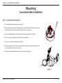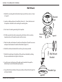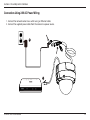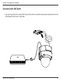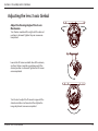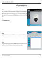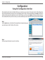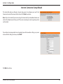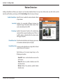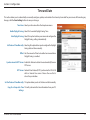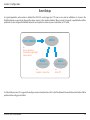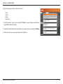
1
Version 1.0 | March 7, 2013 User Manual Full HD WDR Day & Night Outdoor Dome Network Camera DCS-6513 Preface D-Link reserves the right to revise this publication and to make changes in the content hereof without obligation to notify any person or organization of such revisions or changes. Information in this document may become obsolete as our services and websites develop and change. Manual Revisions Revision Date 1.0 March 7, 2013 Description DCS‑6513 Revision A1 with firmware version 1.00 Trademarks D-Link and the D-Link logo are trademarks or registered trademarks of D-Link Corporation or its subsidiaries in the United States or other countries. All other company or product names mentioned herein are trademarks or registered trademarks of their respective companies. Copyright © 2013 D-Link Corporation. All rights reserved. This publication may not be reproduced, in whole or in part, without prior expressed written permission from D-Link Corporation. D-Link DCS-6513 User Manual 2 Table of Contents Product Overview.......................................................................... 4 Package Contents.................................................................. 4 Introduction............................................................................. 5 System Requirements.......................................................... 5 Features..................................................................................... 6 Hardware Overview.............................................................. 7 Front....................................................................................... 7 Cable Harness..................................................................... 8 Internal.................................................................................. 9 Mounting........................................................................................10 Concealed Cable Installation...........................................10 Style 1 - Concealed Cable Installation..........................10 Style 2 - Exposed Cable Installation..............................12 Exposed Cable Installation...........................................12 Pendant Mount.................................................................15 Wall Mount.........................................................................18 Weather Shield Installation..............................................20 Adjusting the lens 3-axis Gimbal...................................24 Software Installation..........................................................25 D-ViewCam Setup Wizard.................................................28 Configuration................................................................................30 Using the Configuration Interface.................................30 Live Video...............................................................................31 Setup........................................................................................33 Setup Wizard.....................................................................33 Network Setup..................................................................39 Dynamic DNS....................................................................42 D-Link DCS-6513 User Manual Image Setup......................................................................43 Audio and Video...............................................................45 Lens Control.......................................................................47 Preset....................................................................................48 Motion Detection............................................................50 Time and Date...................................................................51 Event Setup........................................................................52 SD Card................................................................................60 Advanced................................................................................61 Digital Input/Output.......................................................61 ICR and IR............................................................................62 HTTPS...................................................................................63 Access List...........................................................................64 Maintenance..........................................................................65 Device Management......................................................65 System.................................................................................66 Firmware Upgrade...........................................................67 Status.......................................................................................68 Device Info.........................................................................68 Logs......................................................................................69 Help......................................................................................70 DI/DO Specifications..................................................................71 Technical Specifications............................................................72 Safety Statements.......................................................................75 Contacting Technical Support................................................77 Warranty.........................................................................................78 Registration...................................................................................85 3 Section 1: Product Overview Product Overview Package Contents DCS‑6513 Full HD WDR Day & Night Outdoor Dome Network Camera Weather Shield Power adapter 37mm Screws for Weather Shield CD-ROM with User Manual and software Cable Cover Extension Adapter Rubber Plug Security Wrench Quick Install Guide If any of the above items are missing, please contact your reseller. Note: Using a power supply with a different voltage than the one included with your product will cause damage and void the warranty for this product. D-Link DCS-6513 User Manual 4 Section 1: Product Overview Introduction The DCS‑6513 Full HD WDR Day & Night Outdoor Dome Network Camera is a professional, vandal-resistant surveillance and security solution for small, medium, and large enterprises. The DCS-6513 uses a three megapixel progressive scan CMOS sensor; which results in low noise and high sensitivity with Wide Dynamic Range (WRD) capabilities ideal for surveillance applications. The DCS-6513 is equipped with a P-iris lens that controls the iris with extreme precision. The built-in stepping motor maintains the iris opening at an optimal level at all times, resulting in superior image clarity, depth of field, and image quality. Together with WDR enhancement, users can identify image details in extreme bright, as well as dark environments. The DCS‑6513 has an IP67 certified weatherproof housing designed for both indoor and outdoor applications. The built-in removable IR-cut filter and IR LEDs gives the DCS-6513 the capability to view up to 60 feet at night. The DCS-6513 also incorporates Power over Ethernet (PoE), allowing it to be easily installed in a variety of locations without the need for supplemental power cabling. The combination of IP67 housing, IR-Cut Filter, IR LEDs, and PoE make the DCS-6513 an ideal solution for a high performance, reliable and cost-effective 24 hour HD surveillance solution with an easy, clutter-free installation. System Requirements • Computer with Windows 8, 7, Vista®, or XP (for CD-ROM Setup Wizard); Mac OS® X or Linux • PC with 1.3GHz or above; at least 128MB RAM • Internet Explorer 7 or above, Firefox 3.5 or above, Safari 4, and Chrome 8.0 or above • Existing 10/100 Ethernet-based network • A microSD memory card (optional) is required for recording to onboard storage. SDHC Class 6 or above is recommended. • Broadband Internet connection D-Link DCS-6513 User Manual 5 Section 1: Product Overview Features P-iris The P-iris lens in the DCS‑6513 solves the long-standing problem of capturing sharp images in various light conditions. The DCS‑6513 optimizes the iris opening under all lighting conditions, resulting in images with better clarity, resolution and depth of field as well as improved image sharpness and increased image usability for network video surveillance. Remote Zoom & Focus The remote focus function eliminates the need for manual focusing at the camera position and allowing the user to make key adjustments from any computer. The remote zoom functionality allows the user to make final adjustments to the zoom from the computer. It provides a convenient way to ensure that the viewing angle is optimized for the scene and required need for resolution. Wide Dynamic Range Wide Dynamic Range technology neutralizes imperfect lighting, providing clear images with the right amount of contrast even when a subject is backlit. Automatic Thermostat Temperature Regulation The DCS-6513 monitors and automatically regulates its temperature to ensure optimal performance even in extreme conditions. It balances fan use against a built in heater based on a range of preset thermostatic settings. This gives the DCS-6513 the ability to perform in the most demanding of environments. Remote Monitoring Utility The D-ViewCam application adds enhanced features and functionality for the Network Camera and allows administrators to configure and access the Network Camera from a remote site via Intranet or Internet. Other features include image monitoring, recording images to a hard drive, viewing up to 32 cameras on one screen, and taking snapshots. IR LED for Day and Night Functionality The built-in infrared LEDs enables night time viewing of up to 20 meters (65.6 feet). Robust Weatherproof and Vandal-resistant Housing The DCS‑6513 housing is compliant with both the IP67 weatherproof and IK10 vandal-resistant certifications, allowing you to rest assured that it will continue to provide round-the-clock surveillance in the toughest of conditions and locations. PoE (Power over Ethernet) for Flexible Installation The DCS‑6513 can draw all the power it needs from a PoE switch or PoE injector, negating the need for a separate power installation. D-Link DCS-6513 User Manual 6 Section 1: Product Overview Hardware Overview Front 3 5 2 1 4 1 Camera Lens Varifocal lens to record video of the surrounding area 2 Light Sensor The light sensor measures the lighting conditions and switches between color and infrared accordingly 3 IR LEDs 4 Power/Status LED Indicates the camera's current status 5 Protective Casing The camera is housed in an IP67 certified weatherproof casing, which protects it against rain and dust. This case is also IK10 certified vandal-resistant. D-Link DCS-6513 User Manual Infrared LEDs illuminate the camera's field of view at night 7 Section 1: Product Overview Cable Harness 4 7 3 2 6 1 5 The BNC connector is recommended for use with handheld monitors to check the Field of View during installation. 1 BNC Connector 2 Power Connector 3 Audio In (A.In) 4 Audio Out (A.Out) Connects to a speaker. 5 DI/DO Connector I/O connectors for external devices. 12V DC output. 6 Reset Button 7 24V Power Connector D-Link DCS-6513 User Manual Power connector for the provided 12V DC power adapter. Connects to a microphone. Press and hold the recessed button for ten seconds to reset the camera. Connects to 24V AC power supply. 8 Section 1: Product Overview Internal 1 Disassemble the Camera Open the camera enclosure by loosening the four screws. Then lift the dome off the base of the camera. 1 microSD Card Slot D-Link DCS-6513 User Manual Install the microSD Card Push the microSD card into the camera with the gold contacts oriented towards the base of the camera. To eject, push the microSD card into the slot. Insert a microSD card for local storage of recorded images and video 9 Section 2: Assembly and Installation Mounting Concealed Cable Installation Style 1 - Concealed Cable Installation 1. Disassemble the camera enclosure (see page 9). 2. Thread the cables through the waterproof plugs at the bottom of the base of the camera. Attach the cables to the corresponding cable connectors. (Figure 2.1) 3. Locate a suitable position on the ceiling for the mounting plate to be installed. 4. Use the mounting template to mark the holes for installation. 5. Cut an access hole in the ceiling for the cables. 6. Drill four separate 6mm holes corresponding to the holes in the mounting template and insert the plastic anchors into these holes. 7. Attach the surface bracket to the ceiling using the screws provided. Figure 2.1 D-Link DCS-6513 User Manual 10 Section 2: Assembly and Installation 1. Connect the Ethernet cable and the power cable, threading them through the hole in the ceiling. (Figure 2.2) 2. Push the dome body up over the base of the camera. 3. Attach the dome to the base of the camera using the three long screws and the provided security screw. Figure 2.2 D-Link DCS-6513 User Manual 11 Section 2: Assembly and Installation Exposed Cable Installation Style 2 - Exposed Cable Installation 1. Disassemble the camera enclosure (see page 9). 2. Remove the small screw to release the faceplate on the side of the base of the camera. Figure 2.3 D-Link DCS-6513 User Manual 12 Section 2: Assembly and Installation 1. Disassemble the camera enclosure (see page 9). 2. Remove the small screw to release the faceplate on the side of the base of the camera. 3. Thread the cables through the waterproof plugs on the side of the base of the camera. Attach the cables to the corresponding cable connectors (see page 10). Figure 2.4 4. Attach the dual-holed plate to the base of the camera. (Figure 2.4) D-Link DCS-6513 User Manual 13 Section 2: Assembly and Installation 1. Place the plastic cable cover onto the dual-holed plate and attach it using the screw. (Figure 2.5) 2. Locate a suitable position on the ceiling for the mounting plate to be installed. 3. Use the mounting template to mark the holes for installation. Figure 2.5 4. Drill four separate 6mm holes corresponding to the holes in the mounting template and insert the plastic anchors into these holes. 5. Attach the surface bracket to the ceiling using the screws provided. 6. Place the dome body onto the base of the camera. (Figure 2.6) 7. Attach the dome to the base of the camera using the three long screws and the provided security screw. Figure 2.6 D-Link DCS-6513 User Manual 14 Section 2: Assembly and Installation Pendant Mount 1. Attach the mounting plate to the bracket cap using the three screws as shown in Figure 3.1. Bracket Cap 2. Locate a suitable position on the ceiling for a 34mm (+2 / –0 mm) hole to be cut. A template is included to aid in marking the mounting hole. 3. Cut a hole in the ceiling according to the template. 4. Drill four separate 6mm holes corresponding to the holes in the mounting template and insert the plastic anchors into these holes. 5. Place the rubber seal between the pendant bracket and the ceiling to ensure a waterproof seal between the ceiling and the bracket. (Figure 3.2) 6. Attach the pendant bracket to the ceiling using the screws provided. 7. Attach the bracket cap to the bottom of the pendant bracket by rotating the cap counterclockwise to tighten it into place. 8. Insert the screw into the base of the pendant bracket at the top of the bracket cap to secure the bracket cap into place. Figure 3.1 Mounting Plate Rubber Seal Pendant Bracket Figure 3.2 D-Link DCS-6513 User Manual Bracket Cap 15 Section 2: Assembly and Installation 1. Connect the Ethernet cable and the power cable, then thread them through the pendant bracket. 2. Place the dome body onto the base of the camera. (Figure 3.3) Figure 3.3 D-Link DCS-6513 User Manual 16 Section 2: Assembly and Installation 1. Attach the dome to the base of the camera using the three long screws and the provided security screw. D-Link DCS-6513 User Manual 17 Section 2: Assembly and Installation Wall Mount 1. Attach the mounting plate to the bracket cap using the three screws as shown in Figure 4.1. Bracket Cap 2. Locate a suitable position on the wall for a 34mm (+2 / –0 mm) hole to be cut. A template is included to aid in marking the mounting hole. 3. Cut a hole in the ceiling according to the template 4. Drill four separate 6mm holes corresponding to the holes in the mounting template and insert the plastic anchors into these holes. Mounting Plate Figure 4.1 5. Place the rubber seal between the wall mount bracket and the wall to ensure a waterproof seal between the wall and the bracket. (Figure 4.2) 6. Attach the wall mount bracket to the wall using the screws provided. Wall Mount Bracket 7. Attach the bracket cap to the bottom of the wall mount bracket by rotating the cap counterclockwise to tighten it into place. 8. Insert the screw into the base of the wall mount bracket at the top of the bracket cap to secure the bracket cap into place. Bracket Cap 9. Connect the Ethernet cable and the power cable and thread them through the wall mount bracket. Figure 4.2 D-Link DCS-6513 User Manual 18 Section 2: Assembly and Installation 10. Place the dome body onto the base of the camera. (Figure 4.3) 11. Attach the dome to the base of the camera using the three long screws and the provided security screw. Wall Mount Figure 4.3 Dome Camera Figure 4.4 D-Link DCS-6513 User Manual 19 Section 2: Assembly and Installation Weather Shield Installation The DCS-6513 comes with an optional weather shield to protect your network camera against damage from adverse weather. If you are installing the DCS-6513 in a location where it will be exposed to harsh weather, it is recommended that you install the weather shield. The weather shield should be installed before you commence mounting or connecting the camera in its final location. To install the weather shield, you will require the 37mm screws which were included in the product package. Step 1: Using a screwdriver, remove the existing two screws which were pre-installed in the collar of the camera. Step 2: Place the weather shield over the dome of the camera and align the screw holes with the holes in the collar of the camera. Step 3: Install the 37mm screws into the existing screw holes so that they hold the weather shield in place. Install 37mm Screws Weather Shield Remove Existing Screws D-Link DCS-6513 User Manual 20 Section 2: Assembly and Installation Connection Using 12V DC Power Adapter 1.Connect the network camera to a switch via an Ethernet cable. 2.Connect the supplied power cable from the camera to a power outlet. 2 1 D-Link DCS-6513 User Manual 21 Section 2: Assembly and Installation Connection Using 24V AC Power Wiring 1.Connect the network camera to a switch using an Ethernet cable. 2.Connect the supplied power cable from the camera to a power source. 2 1 D-Link DCS-6513 User Manual 22 Section 2: Assembly and Installation Connection with a PoE Switch 1.If you are using a PoE switch, connect the IP camera to the switch via an Ethernet cable, which will provide transmission of both power and data over a single cable. D-Link DCS-6513 User Manual 23 Section 2: Assembly and Installation Adjusting the lens 3-axis Gimbal Adjust the Viewing Angle of the 3-axis Mechanism Turn the lens module left or right until the desired position is achieved. Tighten the pan screw once completed. Loosen the tilt screws on both sides of the camera, and turn the lens module up and down until the desired position is achieved. Tighten the tilt screws once completed. Turn the lens to adjust the IP camera’s image until the desired orientation is achieved and then tighten the image adjustment screw once completed. D-Link DCS-6513 User Manual 24 Section 2: Assembly and Installation Software Installation Step 1 Insert the Installation CD-ROM into your computer’s CD drive to start the autorun program. Note: If the autorun program does not automatically start on your computer, go to Windows, click Start > Run. In the Run command box type D:\DCS6513.exe, where D: represents your CD-ROM drive. Step 2 Click Setup Wizard to begin. Step 3 Accept the End User Licence Agreement and follow the on-screen prompts to install the camera. Step 4 Select your camera from the list and then click Wizard. If you have multiple cameras, you can identify them by the MAC ID printed on the label on the back of your camera. D-Link DCS-6513 User Manual 25 Section 2: Assembly and Installation Step 5 By default the Admin ID is admin and the password field is left blank. It is recommended that you create and confirm a password for your device. Click Next to continue. Step 6 Select Static IP if you want to manually enter the network settings of your camera or DHCP if you want your router or DHCP server to automatically assign the camera its network settings. Click Next to continue. Note: Select DHCP if you are unsure of which settings to choose. Click Next to continue. D-Link DCS-6513 User Manual 26 Section 2: Assembly and Installation Step 7 Confirm your camera's settings and click Restart. The LED on the front of the DCS‑6513 will blink and then turn solid green once it successfully connects to your network. Step 8 Your DCS‑6513 camera is now set up. Click Exit to exit the wizard. You can skip to "Configuration" on page 30 for advanced configuration of your camera. D-Link DCS-6513 User Manual 27 Section 2: Assembly and Installation D-ViewCam Setup Wizard D-ViewCam software is included for the administrator to manage multiple D-Link IP cameras remotely. You may use the software to configure all the advanced settings for your cameras. D-ViewCam is a comprehensive management tool for IP surveillance. Step 1 Insert the CD-ROM into the CD drive. Click Install D-ViewCam on the left and then click the Install button. Step 2 Follow the Installation Wizard to install D-ViewCam. D-Link DCS-6513 User Manual 28 Section 2: Assembly and Installation Step 3 Click Finish to complete the installation. Step 4 To start D-ViewCam, select Start > All Programs > D-Link D-ViewCam > Main Console. Step 5 For more detailed operation of using D-ViewCam software, please refer to the D-ViewCam manual. D-Link DCS-6513 User Manual 29 Section 3: Configuration Configuration Using the Configuration Interface After completing the Camera Installation Wizard, you are ready to use your camera. The camera’s built-in Web configuration utility is designed to allow you to easily access and configure your DCS‑6513. At the end of the Wizard, click Link, or enter the IP address of your camera into a web browser such as Firefox. To log in, use the User name admin and the password you created in the Installation Wizard. If you did not create a password, the default password is blank. After entering your password, click OK. Step 1 Click the Link button on the Wizard. The Setup Wizard will automatically open your web browser to the IP address of the camera. Step 2 Enter your login information to access the interface. 2 D-Link DCS-6513 User Manual 30 Section 3: Configuration Live Video This section shows your camera’s live video. You may select any of the available icons listed below to operate the camera. You may also select your language using the drop-down menu on the left side of the screen. You can zoom in and out on the live video image using your mouse. Right-click to zoom out or left-click to zoom in on the image. SD Status: This option displays the status of the microSD card. If a microSD card has not been inserted, this screen will display the message "Card Invalid." IO Status: This option displays the status of your I/O device if a device has been connected. Digital Input Indicator Motion Trigger Indicator Recording Indicator Control Pad Auto Pan This indicator will change color when a digital input signal is detected. This indicator will change color when a trigger event occurs. Note: The video motion feature for your camera must be enabled. When a recording is in progress, this indicator will change color. This control pad can be used to electronically pan, tilt, and zoom (ePTZ) within the camera's predefined view area, if one has been defined. Starts the automatic panning function. The ROI will pan from back and forth within the FOV Stop Stops the camera ePTZ motion Preset Path Starts the camera's motion along the predefined path ePTZ Speed: You may select a value between 0 and 10, where 1 is the slowe st and 10 is the fastest. D-Link DCS-6513 User Manual 31 Section 3: Configuration Global View: This window indicates the total Field of View (FOV) of the camera. The red box indicates the visible Region of Interest (ROI). Language: You may select the interface language using this menu. Video Profile 1 Record a Video Clip Video Profile 2 Set a Storage Folder Video Profile 3 Listen/Stop Audio In (from microphone) Full screen mode Start/Stop Audio Out (to speaker) Take a Snapshot Start/Stop Digital Output Go To: If any presets have been defined, selecting a preset from this list will (Preset List) display it. D-Link DCS-6513 User Manual 32 Section 3: Configuration Setup Setup Wizard To configure your Network Camera, click Internet Connection Setup Wizard. Alternatively, you may click Manual Internet Connection Setup to manually configure your Network Camera and skip to "Network Setup" on page 39. To quickly configure your Network Camera’s motion detection settings, click Motion Detection Setup Wizard. If you want to enter your settings without running the wizard, click Manual Motion Detection Setup and skip to "Motion Detection" on page 50. D-Link DCS-6513 User Manual 33 Section 3: Configuration Internet Connection Setup Wizard This wizard will guide you through a step-by-step process to configure your new D-Link Camera and connect the camera to the Internet. Click Next to continue. Note: Only use this wizard if you are connecting the Camera directly to a broadband modem or a switch with multiple accounts from your ISP. If you are connecting to a router or gateway, do not run this wizard. If your Internet service provider has not provided you with connection settings, or you are unsure of which settings to choose, select DHCP. Click Next to continue. D-Link DCS-6513 User Manual 34 Section 3: Configuration Select Static IP if you want to manually enter the network settings of your camera or DHCP if you want your router or DHCP server to automatically assign the camera its network settings. Click Next to continue. If you are using PPPoE, select Enable PPPoE and enter your user name and password, otherwise click Next to continue. If you have a Dynamic DNS account and would like the camera to update your IP address automatically, select Enable DDNS and enter your host information. Click Next to continue. Enter a name for your camera and click Next to continue. D-Link DCS-6513 User Manual 35 Section 3: Configuration Configure the correct time to ensure that all events will be triggered as scheduled. Click Next to continue. Verify that the settings are correct and click Apply to save them. The settings will be saved to the DCS-6513 and the camera will restart. D-Link DCS-6513 User Manual 36 Section 3: Configuration Motion Detection Setup Wizard This wizard will guide you through a step-by-step process to configure your camera's motion detection functions. Click Next to continue. Step 1 This step will allow you to enable or disable motion detection, specify the detection sensitivity, and adjust the camera’s ability to detect movement. You may specify whether the camera should capture a snapshot or a video clip when motion is detected. Please refer to "Motion Detection" on page 50 for information about how to configure motion detection. Step 2 This step allows you to enable motion detection based on a customized schedule. Specify the day and hours. You may also choose to always record whenever motion is detected. D-Link DCS-6513 User Manual 37 Section 3: Configuration Step 3 This step allows you to specify how you will receive event notifications from your camera. You may choose not to receive notifications, or to receive notifications via e-mail or FTP. Please enter the relevant information for your e-mail or FTP account. Click Next to continue. Step 4 You have completed the Motion Detection Wizard. Please verify your settings and click Apply to save them. Please wait a few moments while the camera saves your settings and restarts. D-Link DCS-6513 User Manual 38 Section 3: Configuration Network Setup Use this section to configure the network connections for your camera. All relevant information must be entered accurately. After making any changes, click the Save Settings button to save your changes. LAN Settings: This section lets you configure settings for your local area network. DHCP: Select this connection if you have a DHCP server running on your network and would like your camera to obtain an IP address automatically. If you choose DHCP, you do not need to fill out the IP address settings. Static IP Client: You may obtain a static or fixed IP address and other network information from your network administrator for your camera. A static IP address may simplify access to your camera in the future. IP Address: Enter the fixed IP address in this field. Subnet Mask: This number is used to determine if the destination is in the same subnet. The default value is 255.255.255.0. Default Gateway: The gateway used to forward frames to destinations in a different subnet. Invalid gateway settings may cause the failure of transmissions to a different subnet. Primary DNS: The primary domain name server translates names to IP addresses. Secondary DNS: The secondary DNS acts as a backup to the primary DNS. D-Link DCS-6513 User Manual 39 Section 3: Configuration Enable UPnP Presentation: Enabling this setting allows your camera to be configured as a UPnP device on your network. Enable UPnP Port Forwarding: Enabling this setting allows the camera to add port forwarding entries into the router automatically on a UPnP capable network. Enable PPPoE: Enable this setting if your network uses PPPoE. User Name / Password: Enter the username and password for your PPPoE account. Re-enter your password in the Confirm Password field. You may obtain this information from your ISP. HTTP Port: The default port number is 80. Access Name for Stream 1~3: The default name is video#.mjpg, where # is the number of the stream. HTTPS Port: You may use a PC with a secure browser to connect to the HTTPS port of the camera. The default port number is 443. Authentication: Choose to enable or disable RTSP digest encryption. Digest encryption uses MD5 hashes. RTSP Port: The port number that you use for RTSP streaming to mobile devices, such as mobile phones or PDAs. The default port number is 554. You may specify the address of a particular stream. For instance, live1.sdp can be accessed at rtsp://x.x.x.x/video1.sdp where the x.x.x.x represents the IP address of your camera. D-Link DCS-6513 User Manual 40 Section 3: Configuration Enable CoS: Enabling the Class of Service setting implements a best-effort policy without making any bandwidth reservations. Enable QoS: Enabling QoS allows you to specify a traffic priority policy to ensure a consistent Quality of Service during busy periods. If the Network Camera is connected to a router that itself implements QoS, the router's settings will override the QoS settings of the camera. Enable IPv6: Enable the IPv6 setting to use the IPv6 protocol. Enabling the option allows you to manually set up the address, specify an optional IP address, specify an optional router and an optional primary DNS. Enable Multicast for stream The DCS‑6513 allows you to multicast each of the available streams via group address and specify the TTL value for each stream. Enter the port and TTL settings you wish to use if you do not want to use the defaults. D-Link DCS-6513 User Manual 41 Section 3: Configuration Dynamic DNS DDNS (Dynamic Domain Name Server) will hold a DNS host name and synchronize the public IP address of the modem when it has been modified. A user name and password are required when using the DDNS service. After making any changes, click the Save Settings button to save your changes. Enable DDNS: Select this checkbox to enable the DDNS function. Server Address: Select your Dynamic DNS provider from the pull down menu or enter the server address manually. Host Name: Enter the host name of the DDNS server. User Name: Enter the user name or e-mail used to connect to your DDNS account. Password: Enter the password used to connect to your DDNS server account. Timeout: Enter the DNS timeout values you wish to use. Status: Indicates the connection status, which is automatically determined by the system. D-Link DCS-6513 User Manual 42 Section 3: Configuration Image Setup In this section, you may configure the video image settings for your camera. A preview of the image will be shown in Live Video. Enable Privacy Mask: The Privacy Mask setting allows you to specify up to 3 rectangular areas on the camera's image to be blocked/ excluded from recordings and snapshots. You may click and drag the mouse cursor over the camera image to draw a mask area. Right clicking on the camera image brings up the following menu options: Disable All: Disables all mask areas Enable All: Enables all mask areas Reset All: Clears all mask areas. Mirror: This will mirror the image horizontally. Flip: This will flip the image vertically. When turning Flip on, you may wish to consider turning Mirror on as well. Power Line: Select the frequency used by your power lines to avoid interference or distortion. White Balance: Use the drop-down box to change white balance settings to help balance colors for different environments. You can choose from Auto, Outdoor, Indoor, Fluorescent, and Push Hold. Exposure Mode: Changes the exposure mode. Use the drop-down box to set the camera for Indoor, Outdoor, or Night environments, or to Moving to capture moving objects. The Low Noise option will focus on creating a highquality picture without noise. You can also create 3 different custom exposure modes. The Max Gain setting will allow you to control the maximum amount of gain to apply to brighten the picture. D-Link DCS-6513 User Manual 43 Section 3: Configuration Enable Automatic Iris Adjustment Selecting this option will allow the camera to automatically determine the optimal iris adjustment. Iris Adjustment To counteract difficult lighting scenarios you can manually adjust the camera's iris. Iris Speed This allows you to select the speed at which iris adjustments take place. Denoise: This setting controls the amount of noise reduction that will be applied to the picture. Brightness: Adjust this setting to compensate for backlit subjects. Contrast: Adjust this setting to alter the color intensity/strength. Saturation: This setting controls the amount of coloration, from grayscale to fully saturated. Sharpness: Specify a value from 0 to 128 to specify how much sharpening to apply to the image. WDR Level: Specify a value from 0 to 10 to specify how much WDR to apply to the image, or select None. Reset Default: Click this button to reset the image to factory default settings. D-Link DCS-6513 User Manual 44 Section 3: Configuration Audio and Video You may configure up to 3 video profiles with different settings for your camera. Hence, you may set up different profiles for your computer and mobile display. In addition, you may also configure the two-way audio settings for your camera. After making any changes, click the Save Settings button to save your changes. Aspect ratio: Set the aspect ratio of the video to 4:3 standard or 16:9 widescreen. Mode: Set the video codec to be used to JPEG, MPEG-4, or H.264. Frame size / View window area: Frame size determines the total capture resolution, and View window area determines the Live Video viewing window size. If the Frame size is larger than the Live Video size, you can use the ePTZ controls to look around. 16:9 1920 x 1080, 1280 x 720, 800 x 450, 640 x 360, 480 x 270, 320 x 176, 176 x 144 up to 30 fps 4:3 1600 x 1200, 1024 x 768, 800 x 600, 640 x 480, 320 x 240, 176 x 144 up to 30 fps 2048 x 1536 at 15 fps Note: If your View window area is the same as your Frame size, you will not be able to use the ePTZ function. Maximum frame rate: A higher frame rate provides smoother motion for videos, but requires more bandwidth. Lower frame rates will result in stuttering motion, however, they will require less bandwidth. D-Link DCS-6513 User Manual 45 Section 3: Configuration Video Quality: This limits the maximum frame rate, which can be combined with the "Fixed quality" option to optimize the bandwidth utilization and video quality. If fixed bandwidth utilization is desired regardless of the video quality, choose "Constant bit rate" and select the desired bandwidth. Constant bit rate: The bps will affect the bit rate of the video recorded by the camera. Higher bit rates result in higher video quality. Fixed quality: Select the image quality level for the camera to try to maintain. High quality levels will result in increased bit rates. Audio in off: Selecting this checkbox will mute incoming audio. Audio in gain level: This setting controls the amount of gain applied to incoming audio to increase its volume. Audio out off: Selecting this checkbox will mute outgoing audio. Audio out volume level: This setting controls the amount of gain applied to outgoing audio to increase its volume. D-Link DCS-6513 User Manual 46 Section 3: Configuration Lens Control The settings on this page allow you to remotely fine tune the zoom and focus to achieve optimal performance. Focus Mode: Select an option from the drop down menu. Auto Allow the camera to automatically adjust Manual Show the Focus Slider control to allow manual adjustment. Zoom Control Use the slider control to fine tune the camera zoom. Focus Control Use the slider control to fine tune the camera focus. Fine Tune Focus automatically: Allow the camera to adjust the focus automatically. D-Link DCS-6513 User Manual 47 Section 3: Configuration Preset This screen allows you to set preset points for the ePTZ function of the camera, which allows you to look around the camera's viewable area by using a zoomed view. Presets allow you to quickly go to and view a specific part of the area your camera is covering, and you can create preset sequences, which will automatically change the camera's view between the different presets according to a defined order and timing you can set. Note: If your View window area is the same as your Frame size, you will not be able to use the ePTZ function. Video Profile: This selects which video profile to use. ePTZ Speed: You may select a value between 0 and 10. 0 is the slowest and 10 is the fastest. Arrow Buttons and Home Button: Use these buttons to move to a specific part of the viewing area, which you can then set as a preset. Click the Home button to return to the center of the viewing area. Input Preset Name: Enter the name of the preset you want to create, then click the Add button to make a new preset. If an existing preset has been selected from the Preset List, you can change its name by typing in a new name, then clicking the Rename button. Preset List: Click this drop-down box to see a list of all the presets that have been created. You can select one, then click the GoTo button to change the displayed camera view to the preset. Clicking the Remove button will delete the currently selected preset. Preset Sequence: This section allows you to create a preset sequence, which automatically moves the camera's view between a set of preset views. D-Link DCS-6513 User Manual 48 Section 3: Configuration Preset List: To add a preset to the sequence, select it from the dropdown box at the bottom of this window, set the Dwell time to determine how long the camera view will stay at that preset, then click the Add button. The preset name will appear in the list, followed by the dwell time to view that preset for. You can rearrange your presets in the sequence by selecting a preset in the sequence, then clicking the arrow buttons to move it higher or lower in the current sequence. Clicking the trash can button will remove the currently selected preset from the sequence. If you want to change the dwell time for a preset, select it from the list, enter a new dwell time, then click the Update button. D-Link DCS-6513 User Manual 49 Section 3: Configuration Motion Detection Enabling Video Motion will allow your camera to use the motion detection feature. You may draw a finite motion area that will be used for monitoring. After making any changes, click the Save Settings button to save your changes. Enable Video Motion: Select this box to enable the motion detection feature of your camera. Sensitivity: Specifies the measurable difference between two sequential images that would indicate motion. Please enter a value between 0 and 100. Percentage: Specifies the amount of motion in the window being monitored that is required to initiate an alert. If this is set to 100%, motion is detected within the whole window will trigger a snapshot. Draw Motion Area: Draw the motion detection area by dragging your mouse in the window (indicated by the red square). Erase Motion Area: To erase a motion detection area, simply click on the red square that you wish to remove. Right clicking on the camera image brings up the following menu options: Select All: Draws a motion detection area over the entire screen. Clear All: Clears any motion detection areas that have been drawn. Restore: Restores the previously specified motion detection areas. D-Link DCS-6513 User Manual 50 Section 3: Configuration Time and Date This section allows you to automatically or manually configure, update, and maintain the internal system clock for your camera. After making any changes, click the Save Settings button to save your changes. Time Zone: Select your time zone from the drop-down menu. Enable Daylight Saving: Select this to enable Daylight Saving Time. Auto Daylight Saving: Select this option to allow your camera to configure the Daylight Saving settings automatically. Set Date and Time Manually: Selecting this option allows you to configure the Daylight Saving date and time manually. Offset: Sets the amount of time to be added or removed when Daylight Saving is enabled. Synchronize with NTP Server: Enable this feature to obtain time automatically from an NTP server. NTP Server: Network Time Protocol (NTP) synchronizes the DCS‑6513 with an Internet time server. Choose the one that is closest to your location. Set the Date and Time Manually: This option allows you to set the time and date manually. Copy Your Computer's Time This will synchronize the time information from your PC. Settings: D-Link DCS-6513 User Manual 51 Section 3: Configuration Event Setup In a typical application, when motion is detected, the DCS‑6513 sends images to a FTP server or via e-mail as notifications. As shown in the illustration below, an event can be triggered by various sources, such as motion detection. When an event is triggered, a specified action will be performed. You can configure the Network Camera to send snapshots or videos to your e-mail address or FTP server. Action Event Condition ex. Motion detection, Periodically, Digital input, System reboot Media (what to send) ex. Snapshot, Video Clips Server (where to send) ex. Email, FTP To start plotting an event, it is suggested to configure server and media columns first so that the Network Camera will know what action shall be performed when a trigger is activated. D-Link DCS-6513 User Manual 52 Section 3: Configuration The Event Setup page includes 4 different sections. • Event • Server • Media • Recording 1. To add a new item - "event, server or media," click Add. A screen will appear and allow you to update the fields accordingly. 2. To delete the selected item from the pull-down menu of event, server or media, click Delete. 3. Click on the item name to pop up a window for modifying. D-Link DCS-6513 User Manual 53 Section 3: Configuration Add Server You can configure up to 5 servers to save snapshots and/or video to. After making any changes, click the Save Settings button to save your changes. Server Name: Enter the unique name of your server. E-mail: Enter the configuration for the target e-mail server account. FTP: Enter the configuration for the target FTP server account. Network Storage: Specify a network storage device. Only one network storage device is supported. SD Card: Use the camera's onboard microSD card storage. D-Link DCS-6513 User Manual 54 Section 3: Configuration Add Media There are three types of media, Snapshot, Video Clip, and System Log. After making any changes, click the Save Settings button to save your changes. Media Name: Enter a unique name for media type you want to create. Snapshot: Select this option to set the media type to snapshots. Source: Set the video profile to use as the media source. Refer to "Audio and Video" on page 45 for more information on video profiles. Send pre-event image(s) [0~4]: Set the number of pre-event images to take. Pre-event images are images taken before the main event snapshot is taken. Send post-event image(s) [0~7]: Set the number of post-event images to take. Post-event images are images taken after the main event snapshot is taken. You can set up to 7 post-event images to be taken. For example: If both the Send pre-event images and Send post-event images are set to four, a total of 9 images are generated after a trigger is activated. 1 pic. 2 pic. 3 pic. 4 pic. 5 pic. 6 pic. 7 pic. 8 pic. 9 pic. The moment the trigger is activated. D-Link DCS-6513 User Manual 55 Section 3: Configuration File name prefix: The prefix name will be added on the file name. SNAPSHOTS20080104_100341 File name prefix Date and time suffix The format is: YYYYMMDD_HHMMSS Add date and time suffix to file Check this to add timing information as file name suffix. name: Video clip: Select this option to set the media type to video clips. Source: Set the video profile to use as the media source. Refer to "Audio and Video" on page 45 for more information on video profiles. Pre-event recording: This sets how many seconds to record before the main event video clip starts. You can record up to 4 seconds of pre-event video. Maximum duration: Set the maximum length of video to record for your video clips. Maximum file size: Set the maximum file size to record for your video clips. System log: Select this option to set the media type to system logs. This will save the event to the camera system log, but will not record any snapshots or video. D-Link DCS-6513 User Manual 56 Section 3: Configuration Add Event Create and schedule up to 3 events with their own settings here. After making any changes, click the Save Settings button to save your changes. Event name: Enter a name for the event. Enable this event: Select this box to activate this event. Priority: Set the priority for this event. The event with higher priority will be executed first. Delay: Select the delay time before checking the next event. It is being used for both events of motion detection and digital input trigger. Trigger: Specify the input type that triggers the event. Video Motion Detection: Motion is detected during live video monitoring. Select the windows that need to be monitored. Periodic: The event is triggered in specified intervals. The trigger interval unit is in minutes. Digital Input: The external trigger input to the camera. System Boot: Triggers an event when the system boots up. Network Lost: Triggers an event when the network connection is lost. Time: Select Always or enter the time interval. Server: Specify the location where the event information should be saved to. D-Link DCS-6513 User Manual 57 Section 3: Configuration Add Recording Here you can configure and schedule the recording settings. After making any changes, click the Save Settings button to save your changes. Recording entry name: The unique name of the entry. Enable this recording: Select this to enable the recording function. Priority: Set the priority for this entry. The entry with a higher priority value will be executed first. Source: The source of the stream. Recording schedule: Scheduling the recording entry. Recording settings: Configuring the setting for the recording. Destination: Select the folder where the recording file will be stored. Total cycling recording size: Please input a HDD volume between 1MB and 2TB for recording space. The recording data will replace the oldest record when the total recording size exceeds this value. For example, if each recording file is 6MB, and the total cyclical recording size is 600MB, then the camera will record 100 files in the specified location (folder) and then will delete the oldest file and create new file for cyclical recording. Please note that if the free HDD space is not enough, the recording will stop. Before you set up this option please make sure your HDD has enough space. It is advised not to save other files in the same folder as recording files. D-Link DCS-6513 User Manual 58 Section 3: Configuration Size of each file for recording: If this is selected, files will be separated based on the file size you specify. Time of each file for recording: If this is selected, files will be separated based on the maximum length you specify. File Name Prefix: The prefix name will be added on the file name of the recording file(s). D-Link DCS-6513 User Manual 59 Section 3: Configuration SD Card Here you may browse and manage the recorded files which are stored on the microSD card. Format SD Card: Click this icon to automatically format the microSD card and create "picture" & "video" folders. View Recorded Picture: If the picture files are stored on the microSD card, click on the picture folder and choose the picture file you would like to view. Playback Recorded Video: If video files are stored on the microSD card, click on the video folder and choose the video file you would like to view. Refresh: Reloads the file and folder information from the microSD card. D-Link DCS-6513 User Manual 60 Section 3: Configuration Advanced Digital Input/Output This screen allows you to control the behavior of digital input and digital output devices. The I/O connector provides the physical interface for digital output (DO) and digital input (DI) that is used for connecting a variety of external alarm devices such as IR-Sensors and alarm relays. The digital input is used for connecting external alarm devices and once triggered images will be taken and e-mailed. After making any changes, click the Save Settings button to save your changes. Select D/I or D/O Mode: The camera will send a signal when an event is triggered, depending upon the type of device connected to the DI circuit. N.C. stands for Normally Closed. This means that the normal state of the circuit is closed. Therefore events are triggered when the device status changes to "Open." N.O. stands for Normally Open. This means that the normal state of the circuit is open. Therefore events are triggered when the device status changes to "Closed." Video Output: Enable/ disable the BNC terminal TV output signal. D-Link DCS-6513 User Manual 61 Section 3: Configuration ICR and IR Here you can configure the ICR and IR settings. An IR(Infrared) Cut-Removable (ICR) filter can be disengaged for increased sensitivity in low light environments. Automatic: The Day/Night mode is set automatically. Generally, the camera uses Day mode and switches to Night mode when needed. Day Mode: Day mode enables the IR Cut Filter. Night Mode: Night mode disables the IR Cut Filter. Schedule Mode: Set up the Day/Night mode using a schedule. The camera will enter Day mode at the starting time and return to Night mode at the ending time. IR Light Control: The camera can enable or disable the IR (infrared) light according to your preferences. This setting provides additional controls depending on your specific application. Off: The IR light will always be off. On: The IR light will always be on. Sync: The IR light will turn on when the ICR sensor is on. Schedule: The IR light will turn on or off according to the schedule that you specify below. D-Link DCS-6513 User Manual 62 Section 3: Configuration HTTPS This page allows you to install and activate an HTTPS certificate for secure access to your camera. After making any changes, click the Save Settings button to save your changes. Enable HTTPS Secure Connection: Enable the HTTPS service. Create Certificate Method: Choose the way the certificate should be created. Three options are available: Create a self-signed certificate automatically Create a self-signed certificate manually Create a certificate request and install Status: Displays the status of the certificate. Note: The certificate cannot be removed while the HTTPS is still enabled. To remove the certificate, you must first uncheck Enable HTTPS secure connection. D-Link DCS-6513 User Manual 63 Section 3: Configuration Access List Here you can set access permissions for users to view your DCS‑6513. Allow list: The list of IP addresses that have the access right to the camera. Start IP address: The starting IP Address of the devices (such as a computer) that have permission to access the video of the camera. Click Add to save the changes made. Note: A total of seven lists can be configured for both columns. End IP address: The ending IP Address of the devices (such as a computer) that have permission to access the video of the camera. Delete allow list: Remove the customized setting from the Allow List. Deny list: The list of IP addresses that have no access rights to the camera. Delete deny list: Remove the customized setting from the Delete List. For example: When the range of the Allowed List is set from 1.1.1.0 to 192.255.255.255 and the range of the Denied List is set from 1.1.1.0 to 170.255.255.255. Only users with IPs located between 171.0.0.0 and 192.255.255.255 can access the Network Camera. D-Link DCS-6513 User Manual Alowed List Denied List 64 Section 3: Configuration Maintenance Device Management You may modify the name and administrator’s password of your camera, as well as add and manage the user accounts for accessing the camera. You may also use this section to create a unique name and configure the OSD settings for your camera. Admin Password Setting: Set a new password for the administrator’s account. Add User Account: Add new user account. User Name: The user name for the new account. Password: The password for the new account. User List: All the existing user accounts will be displayed here. You may delete accounts included in the list, but you may want to reserve at least one as a guest account. Camera Name: Create a unique name for your camera that will be added to the file name prefix when creating a snapshot or a video clip. Enable OSD: Select this option to enable the On-Screen Display feature for your camera. Label: Enter a label for the camera, which will be shown on the OSD when it is enabled. Show Time: Select this option to enable the time-stamp display on the video screen. D-Link DCS-6513 User Manual 65 Section 3: Configuration System In this section, you may backup, restore and reset the camera configuration, or reboot the camera. Save To Local Hard Drive: You may save your current camera configuration as a file on your computer. Load From Local Hard Drive: Locate a pre-saved configuration by clicking Browse and then restore the pre-defined settings to your camera by clicking Load Configuration. Restore to Factory Default: You may reset your camera and restore the factory settings by clicking Restore Factory Defaults. Reboot Device: This will restart your camera. D-Link DCS-6513 User Manual 66 Section 3: Configuration Firmware Upgrade The camera's current firmware version will be displayed on this screen. You may visit the D-Link Support Website to check for the latest available firmware version. To upgrade the firmware on your DCS‑6513, please download and save the latest firmware version from the D-Link Support Page to your local hard drive. Locate the file on your local hard drive by clicking the Browse button. Select the file and click the Upload button to start upgrading the firmware. Current Firmware Version: Displays the detected firmware version. Current Product Name: Displays the camera model name. File Path: Locate the file (upgraded firmware) on your hard drive by clicking Browse. Upload: Uploads the new firmware to your camera. D-Link DCS-6513 User Manual 67 Section 3: Configuration Status Device Info This page displays detailed information about your device and network connection. D-Link DCS-6513 User Manual 68 Section 3: Configuration Logs This page displays the log information of your camera. You may download the information by clicking Download. You may also click Clear to delete the saved log information. D-Link DCS-6513 User Manual 69 Section 3: Configuration Help This page provides helpful information regarding camera operation. D-Link DCS-6513 User Manual 70 Section 4: DI/DO Specifications DI/DO Specifications D-Link DCS-6513 User Manual 71 Appendix A: Technical Specifications Technical Specifications Camera Network Camera Hardware Profile 1/2.8” 3 Megapixel progressive CMOS sensor 20 meter IR illumination distance Minimum illumination 0 Lux with IR LED on Built-in Infrared-Cut Removable (ICR) Filter module 10x digital zoom 3~9mm vari focal lens Aperture F=1.2~2.3 Angle of view (16:9) -(H) 96.4° ~ 31.6° -(V) 51.2° ~ 17.7° -(D) 114.1° ~ 36.3° Camera Housing IP67 compliant weatherproof housing IK10 vandal-proof compliant Image Features Configurable image size, quality, frame rate, and bit rate Time stamp and text overlays Configurable motion detection windows Configurable privacy mask zones Configurable shutter speed, brightness, saturation, contrast, sharpness, zoom, focus, and aperture. Video Compression Simultaneous H.264/MPEG-4/MJPEG format compression H.264/MPEG-4 multicast streaming JPEG for still images Video Resolution 16:9 - 1920 x 1080,1280 x 720, 800 x 450, 640 x 360, 480 x 270, 320 x 176, 176 x 144 up to 30 fps. 4:3 - 2048x1536(@15fps), 1600x1200, 1024x768, 800x600,640x48 0,480x360,320x240,176x144@ 30fps Audio Support G.726 G.711 External Device Interface 10/100 BASE-TX Ethernet port with PoE 1 DI / 1 DO DC12 V, 100 mA Output microSD card Slot Audio input / output DI/DO connector 12 V DC output Network Protocols IPv6 IPv4 TCP/IP UDP ICMP DHCP client NTP client (D-Link) DNS client DDNS client (D-Link) SMTP client FTP client HTTP / HTTPS Samba client PPPoE UPnP port forwarding RTP / RTSP/ RTCP IP filtering QoS CoS Multicast ONVIF compliant Security Administrator and user group protection Password authentication HTTP and RTSP digest encryption D-Link DCS-6513 User Manual 72 Appendix A: Technical Specifications System System Management Requirements for Web Interface General Browser: Internet Explorer, Firefox, Chrome, or Safari Event Management Motion detection Event notification and uploading of snapshots/video clips via e-mail or FTP Supports multiple SMTP and FTP servers Multiple event notifications Multiple recording methods for easy backup Remote Management Take snapshots/video clips and save to local hard drive or NAS via web browser Configuration interface accessible via web browser OS Support Windows 7/Vista/XP/2000 D-ViewCam™ System Operating System: Microsoft Windows 7/Vista/XP Requirements Web Browser: Internet Explorer 7 or higher Protocol: Standard TCP/IP D-ViewCam™ Software Functions Remote management/control of up to 32 cameras Viewing of up to 32 cameras on one screen Supports all management functions provided in web interface Scheduled event triggered or manual recording options Weight 1.53kg (with Weather Shield) External Power Adapter Input: 100 to 240 V AC, 50/60 Hz Output: 12 V DC 1.25 A Power Consumption 10.5 +-5% Watt Temperature Operating: -40 to 50 °C (-40 to 122 °F) Storage: -20° to 70° C (-4° to 158° F) Humidity Operating: 20% to 80% non-condensing Storage: 5% to 95% non-condensing Certifications CE CE LVD FCC C-Tick DCS-34-2 Pendant Mount DCS-34-3 Bent Arm Mount Optional Accessories D-Link DCS-6513 User Manual 73 Appendix A: Technical Specifications Dimensions D-Link DCS-6513 User Manual 74 Appendix B: Safety Statements Safety Statements CE Mark Warning: This is a Class B product. In a domestic environment, this product may cause radio interference, in which case the user may be required to take adequate measures. FCC Statement: This equipment has been tested and found to comply with the limits for a Class B digital device, pursuant to part 15 of the FCC Rules. These limits are designed to provide reasonable protection against harmful interference in a residential installation. This equipment generates, uses, and can radiate radio frequency energy and, if not installed and used in accordance with the instructions, may cause harmful interference to radio communication. However, there is no guarantee that interference will not occur in a particular installation. If this equipment does cause harmful interference to radio or television reception, which can be determined by turning the equipment off and on, the user is encouraged to try to correct the interference by one or more of the following measures: • Reorient or relocate the receiving antenna. • Increase the separation between the equipment and receiver. • Connect the equipment into an outlet on a circuit different from that to which the receiver is connected. • Consult the dealer or an experienced radio/TV technician for help. FCC Caution: Any changes or modifications not expressly approved by the party responsible for compliance could void the user’s authority to operate this equipment. This device complies with Part 15 of the FCC Rules. Operation is subject to the following two conditions: (1) This device may not cause harmful interference, and (2) this device must accept any interference received, including interference that may cause undesired operation. D-Link DCS-6513 User Manual 75 Appendix B: Safety Statements IMPORTANT NOTICE: FCC Radiation Exposure Statement: This equipment complies with FCC radiation exposure limits set forth for an uncontrolled environment. This equipment should be installed and operated with minimum distance 20cm between the radiator & your body. This transmitter must not be co-located or operating in conjunction with any other antenna or transmitter. The availability of some specific channels and/or operational frequency bands are country dependent and are firmware programmed at the factory to match the intended destination. The firmware setting is not accessible by the end user. For detailed warranty information applicable to products purchased outside the United States, please contact the corresponding local D-Link office. Industry Canada Notice: This device complies with RSS-210 of the Industry Canada Rules. Operation is subject to the following two conditions: (1) This device may not cause harmful interference, and (2) this device must accept any interference received, including interference that may cause undesired operation. IMPORTANT NOTE: Radiation Exposure Statement: This equipment complies with IC radiation exposure limits set forth for an uncontrolled environment. This equipment should be installed and operated with minimum distance 20cm between the radiator & your body. D-Link DCS-6513 User Manual 76 Appendix C: Contacting Technical Support Contacting Technical Support U.S. and Canadian customers can contact D-Link technical support through our web site or by phone. Before you contact technical support, please have the following ready: • Model number of the product (e.g. DCS-6513) • Hardware Revision (located on the label on the bottom of the camera (e.g. rev A1)) • Serial Number (s/n number located on the label on the bottom of the camera). You can find software updates and user documentation on the D-Link website as well as frequently asked questions and answers to technical issues. For customers within the United States: Phone Support: (877) 354-6555 Internet Support: http://support.dlink.com D-Link DCS-6513 User Manual For customers within Canada: Phone Support: (877) 354-6560 Internet Support: http://support.dlink.ca 77 Appendix D: Warranty Warranty Subject to the terms and conditions set forth herein, D-Link Systems, Inc. (“D-Link”) provides this Limited Warranty: • Only to the person or entity that originally purchased the product from D-Link or its authorized reseller or distributor, and • Only for products purchased and delivered within the fifty states of the United States, the District of Columbia, U.S. Possessions or Protectorates, U.S. Military Installations, or addresses with an APO or FPO. Limited Warranty: D-Link warrants that the hardware portion of the D-Link product described below (“Hardware”) will be free from material defects in workmanship and materials under normal use from the date of original retail purchase of the product, for the period set forth below (“Warranty Period”), except as otherwise stated herein. • Hardware (excluding power supplies and fans): Five (5) years • Power supplies and fans: One (1) year • Spare parts and spare kits: Ninety (90) days The customer’s sole and exclusive remedy and the entire liability of D-Link and its suppliers under this Limited Warranty will be, at D-Link’s option, to repair or replace the defective Hardware during the Warranty Period at no charge to the original owner or to refund the actual purchase price paid. Any repair or replacement will be rendered by D-Link at an Authorized D-Link Service Office. The replacement hardware need not be new or have an identical make, model or part. D-Link may, at its option, replace the defective Hardware or any part thereof with any reconditioned product that D-Link reasonably determines is substantially equivalent (or superior) in all material respects to the defective Hardware. Repaired or replacement hardware will be warranted for the remainder of the original Warranty Period or ninety (90) days, whichever is longer, and is subject to the same limitations and exclusions. If a material defect is incapable of correction, or if D-Link determines that it is not practical to repair or replace the defective Hardware, the actual price paid by the original purchaser for the defective Hardware will be refunded by D-Link upon return to D-Link of the defective Hardware. All Hardware or part thereof that is replaced by D-Link, or for which the purchase price is refunded, shall become the property of D-Link upon replacement or refund. D-Link DCS-6513 User Manual 78 Appendix D: Warranty Limited Software Warranty: D-Link warrants that the software portion of the product (“Software”) will substantially conform to D-Link’s then current functional specifications for the Software, as set forth in the applicable documentation, from the date of original retail purchase of the Software for a period of ninety (90) days (“Software Warranty Period”), provided that the Software is properly installed on approved hardware and operated as contemplated in its documentation. D-Link further warrants that, during the Software Warranty Period, the magnetic media on which D-Link delivers the Software will be free of physical defects. The customer’s sole and exclusive remedy and the entire liability of D-Link and its suppliers under this Limited Warranty will be, at D-Link’s option, to replace the non-conforming Software (or defective media) with software that substantially conforms to D-Link’s functional specifications for the Software or to refund the portion of the actual purchase price paid that is attributable to the Software. Except as otherwise agreed by DLink in writing, the replacement Software is provided only to the original licensee, and is subject to the terms and conditions of the license granted by D-Link for the Software. Replacement Software will be warranted for the remainder of the original Warranty Period and is subject to the same limitations and exclusions. If a material non-conformance is incapable of correction, or if D-Link determines in its sole discretion that it is not practical to replace the non-conforming Software, the price paid by the original licensee for the non-conforming Software will be refunded by D-Link; provided that the non-conforming Software (and all copies thereof ) is first returned to D-Link. The license granted respecting any Software for which a refund is given automatically terminates. Non-Applicability of Warranty: The Limited Warranty provided hereunder for Hardware and Software portions of D-Link’s products will not be applied to and does not cover any refurbished product and any product purchased through the inventory clearance or liquidation sale or other sales in which D-Link, the sellers, or the liquidators expressly disclaim their warranty obligation pertaining to the product and in that case, the product is being sold “As-Is” without any warranty whatsoever including, without limitation, the Limited Warranty as described herein, notwithstanding anything stated herein to the contrary. Submitting A Claim (USA): The customer shall return the product to the original purchase point based on its return policy. In case the return policy period has expired and the product is within warranty, the customer shall submit a claim to D-Link as outlined below: • The customer must submit with the product as part of the claim a written description of the Hardware defect or Software nonconformance in sufficient detail to allow DLink to confirm the same, along with proof of purchase of the product (such as a copy of the dated purchase invoice for the product) if the product is not registered. • The customer must obtain a Case ID Number from D-Link Technical Support at 1-877-354-6555, who will attempt to assist the customer in resolving any suspected defects with the product. If the product is considered defective, the customer must obtain a Return Material Authorization (“RMA”) number by completing the RMA form and entering the assigned Case ID Number at https://rma.dlink.com/. D-Link DCS-6513 User Manual 79 Appendix D: Warranty • After an RMA number is issued, the defective product must be packaged securely in the original or other suitable shipping package to ensure that it will not be damaged in transit, and the RMA number must be prominently marked on the outside of the package. Do not include any manuals or accessories in the shipping package. DLink will only replace the defective portion of the product and will not ship back any accessories. • The customer is responsible for all in-bound shipping charges to D-Link. No Cash on Delivery (“COD”) is allowed. Products sent COD will either be rejected by D-Link or become the property of D-Link. Products shall be fully insured by the customer and shipped to D-Link Systems, Inc., 17595 Mt. Herrmann, Fountain Valley, CA 92708. D-Link will not be held responsible for any packages that are lost in transit to D-Link. The repaired or replaced packages will be shipped to the customer via UPS Ground or any common carrier selected by D-Link. Return shipping charges shall be prepaid by D-Link if you use an address in the United States, otherwise we will ship the product to you freight collect. Expedited shipping is available upon request and provided shipping charges are prepaid by the customer. D-Link may reject or return any product that is not packaged and shipped in strict compliance with the foregoing requirements, or for which an RMA number is not visible from the outside of the package. The product owner agrees to pay D-Link’s reasonable handling and return shipping charges for any product that is not packaged and shipped in accordance with the foregoing requirements, or that is determined by D-Link not to be defective or non-conforming. Submitting A Claim (Canada): The customer shall return the product to the original purchase point based on its return policy. In case the return policy period has expired and the product is within warranty, the customer shall submit a claim to D-Link as outlined below: • Customers need to provide their receipt (proof of purchase) even if the product is registered. Without a receipt, no warranty service will be done. The registration is not considered a proof of purchase. • The customer must submit with the product as part of the claim a written description of the Hardware defect or Software nonconformance in sufficient detail to allow D-Link to confirm the same, along with proof of purchase of the product (such as a copy of the dated purchase invoice for the product) if the product is not registered. • The customer must obtain a Case ID Number from D-Link Technical Support at 1-800-361-5265, who will attempt to assist the customer in resolving any suspected defects with the product. If the product is considered defective, the customer must obtain a Return Material Authorization (“RMA”) number by completing the RMA form and entering the assigned Case ID Number at https://rma.dlink.ca/. • After an RMA number is issued, the defective product must be packaged securely in the original or other suitable shipping package to ensure that it will not be damaged in transit, and the RMA number must be prominently marked on the outside of the package. Do not include any manuals or accessories in the shipping package. D-Link will only replace the defective portion of the product and will not ship back any accessories. D-Link DCS-6513 User Manual 80 Appendix D: Warranty • The customer is responsible for all in-bound shipping charges to D-Link. No Cash on Delivery (“COD”) is allowed. Products sent COD will be rejected by D-Link. Products shall be fully insured by the customer and shipped to D-Link Networks, Inc., 2525 Meadowvale Boulevard Mississauga, Ontario, L5N 5S2 Canada. D-Link will not be held responsible for any packages that are lost in transit to D-Link. The repaired or replaced packages will be shipped to the customer via Purolator Canada or any common carrier selected by D-Link. Return shipping charges shall be prepaid by D-Link if you use an address in Canada, otherwise we will ship the product to you freight collect. Expedited shipping is available upon request and provided shipping charges are prepaid by the customer. D-Link may reject or return any product that is not packaged and shipped in strict compliance with the foregoing requirements, or for which an RMA number is not visible from the outside of the package. The product owner agrees to pay D-Link’s reasonable handling and return shipping charges for any product that is not packaged and shipped in accordance with the foregoing requirements, or that is determined by D-Link not to be defective or non-conforming. • RMA phone number: 1-800-361-5265 Hours of Operation: Monday-Friday, 9:00AM – 9:00PM EST What Is Not Covered: The Limited Warranty provided herein by D-Link does not cover: Products that, in D-Link’s judgment, have been subjected to abuse, accident, alteration, modification, tampering, negligence, misuse, faulty installation, lack of reasonable care, repair or service in any way that is not contemplated in the documentation for the product, or if the model or serial number has been altered, tampered with, defaced or removed; Initial installation, installation and removal of the product for repair, and shipping costs; Operational adjustments covered in the operating manual for the product, and normal maintenance; Damage that occurs in shipment, due to act of God, failures due to power surge, and cosmetic damage; Any hardware, software, firmware or other products or services provided by anyone other than D-Link; and Products that have been purchased from inventory clearance or liquidation sales or other sales in which D-Link, the sellers, or the liquidators expressly disclaim their warranty obligation pertaining to the product. While necessary maintenance or repairs on your Product can be performed by any company, we recommend that you use only an Authorized D-Link Service Office. Improper or incorrectly performed maintenance or repair voids this Limited Warranty. Disclaimer of Other Warranties: EXCEPT FOR THE LIMITED WARRANTY SPECIFIED HEREIN, THE PRODUCT IS PROVIDED “AS-IS” WITHOUT ANY WARRANTY OF ANY KIND WHATSOEVER INCLUDING, WITHOUT LIMITATION, ANY WARRANTY OF MERCHANTABILITY, FITNESS FOR A PARTICULAR PURPOSE AND NONINFRINGEMENT. D-Link DCS-6513 User Manual 81 Appendix D: Warranty • The customer is responsible for all in-bound shipping charges to D-Link. No Cash on Delivery (“COD”) is allowed. Products sent COD will be rejected by D-Link. Products shall be fully insured by the customer and shipped to D-Link Networks, Inc., 2525 Meadowvale Boulevard Mississauga, Ontario, L5N 5S2 Canada. D-Link will not be held responsible for any packages that are lost in transit to D-Link. The repaired or replaced packages will be shipped to the customer via Purolator Canada or any common carrier selected by D-Link. Return shipping charges shall be prepaid by D-Link if you use an address in Canada, otherwise we will ship the product to you freight collect. Expedited shipping is available upon request and provided shipping charges are prepaid by the customer. D-Link may reject or return any product that is not packaged and shipped in strict compliance with the foregoing requirements, or for which an RMA number is not visible from the outside of the package. The product owner agrees to pay D-Link’s reasonable handling and return shipping charges for any product that is not packaged and shipped in accordance with the foregoing requirements, or that is determined by D-Link not to be defective or non-conforming. • RMA phone number: 1-800-361-5265 Hours of Operation: Monday-Friday, 9:00AM – 9:00PM EST What Is Not Covered: The Limited Warranty provided herein by D-Link does not cover: Products that, in D-Link’s judgment, have been subjected to abuse, accident, alteration, modification, tampering, negligence, misuse, faulty installation, lack of reasonable care, repair or service in any way that is not contemplated in the documentation for the product, or if the model or serial number has been altered, tampered with, defaced or removed; Initial installation, installation and removal of the product for repair, and shipping costs; Operational adjustments covered in the operating manual for the product, and normal maintenance; Damage that occurs in shipment, due to act of God, failures due to power surge, and cosmetic damage; Any hardware, software, firmware or other products or services provided by anyone other than D-Link; and Products that have been purchased from inventory clearance or liquidation sales or other sales in which D-Link, the sellers, or the liquidators expressly disclaim their warranty obligation pertaining to the product. While necessary maintenance or repairs on your Product can be performed by any company, we recommend that you use only an Authorized D-Link Service Office. Improper or incorrectly performed maintenance or repair voids this Limited Warranty. Disclaimer of Other Warranties: EXCEPT FOR THE LIMITED WARRANTY SPECIFIED HEREIN, THE PRODUCT IS PROVIDED “AS-IS” WITHOUT ANY WARRANTY OF ANY KIND WHATSOEVER INCLUDING, WITHOUT LIMITATION, ANY WARRANTY OF MERCHANTABILITY, FITNESS FOR A PARTICULAR PURPOSE AND NONINFRINGEMENT. D-Link DCS-6513 User Manual 82 Appendix D: Warranty CE Mark Warning: This is a Class B product. In a domestic environment, this product may cause radio interference, in which case the user may be required to take adequate measures. FCC Statement: This equipment has been tested and found to comply with the limits for a Class B digital device, pursuant to part 15 of the FCC Rules. These limits are designed to provide reasonable protection against harmful interference in a residential installation. This equipment generates, uses, and can radiate radio frequency energy and, if not installed and used in accordance with the instructions, may cause harmful interference to radio communication. However, there is no guarantee that interference will not occur in a particular installation. If this equipment does cause harmful interference to radio or television reception, which can be determined by turning the equipment off and on, the user is encouraged to try to correct the interference by one or more of the following measures: • Reorient or relocate the receiving antenna. • Increase the separation between the equipment and receiver. • Connect the equipment into an outlet on a circuit different from that to which the receiver is connected. • Consult the dealer or an experienced radio/TV technician for help. FCC Caution: Any changes or modifications not expressly approved by the party responsible for compliance could void the user’s authority to operate this equipment. This device complies with Part 15 of the FCC Rules. Operation is subject to the following two conditions: (1) This device may not cause harmful interference, and (2) this device must accept any interference received, including interference that may cause undesired operation. IMPORTANT NOTICE: FCC Radiation Exposure Statement: This equipment complies with FCC radiation exposure limits set forth for an uncontrolled environment. This equipment should be installed and operated with minimum distance 20cm between the radiator & your body. This transmitter must not be co-located or operating in conjunction with any other antenna or transmitter. The availability of some specific channels and/or operational frequency bands are country dependent and are firmware programmed at the factory to match the intended destination. The firmware setting is not accessible by the end user. D-Link DCS-6513 User Manual 83 Appendix D: Warranty For detailed warranty information applicable to products purchased outside the United States, please contact the corresponding local D-Link office. Industry Canada Statement: This device complies with RSS-210 of the Industry Canada Rules. Operation is subject to the following two conditions: (1) This device may not cause harmful interference, and (2) this device must accept any interference received, including interference that may cause undesired operation. IMPORTANT NOTE: Radiation Exposure Statement: This equipment complies with Canada radiation exposure limits set forth for an uncontrolled environment. This equipment should be installed and operated with minimum distance 20cm between the radiator and your body. This device has been designed to operate with an antenna having a maximum gain of 2 dB. Antenna having a higher gain is strictly prohibited per regulations of Industry Canada. The required antenna impedance is 50 ohms. D-Link DCS-6513 User Manual 84 Appendix E: Registration Registration Product registration is entirely voluntary and failure to complete or return this form will not diminish your warranty rights. Version 1.0 March 7, 2013 D-Link DCS-6513 User Manual 85