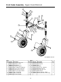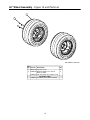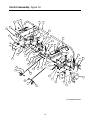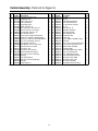
1
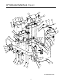
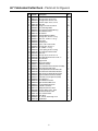
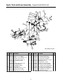
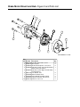
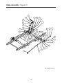
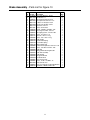
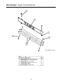
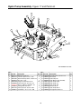
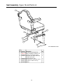
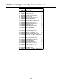
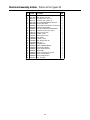
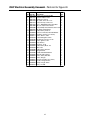
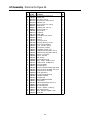
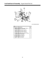
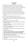
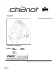
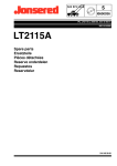
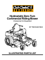
Hydrostatic Zero-Turn
Commercial Riding Mower
Professional Turf Equipment
60" Fabricated Deck
ILLUSTRATED PARTS LIST
TABLE OF CONTENTS
Frame Assembly . . . . . . . . . . . . . . . . . . . . . . . . . . . . . . . . . . 3
60" Fabricated Cutter Deck. . . . . . . . . . . . . . . . . . . . . 4 and 5
60" Spindle Assembly. . . . . . . . . . . . . . . . . . . . . . . . . 6 and 7
Hydro Tank and Hose Assembly. . . . . . . . . . . . . . . . . . . . . . 8
Brake Motor Mount and Hub. . . . . . . . . . . . . . . . . . . . . . . . . 9
Brake Assembly . . . . . . . . . . . . . . . . . . . . . . . . . . . 10 and 11
Fuel Tank Assembly . . . . . . . . . . . . . . . . . . . . . . . . . . . . . . 12
Rear Bumper . . . . . . . . . . . . . . . . . . . . . . . . . . . . . . . . . . . 13
Front Caster Assembly . . . . . . . . . . . . . . . . . . . . . . . . . . . . 14
60" Wheel Assembly. . . . . . . . . . . . . . . . . . . . . . . . . . . . . . 15
Control Assembly . . . . . . . . . . . . . . . . . . . . . . . . . . 16 and 17
Hydro Pump Assembly . . . . . . . . . . . . . . . . . . . . . . . . . . . . 18
Seat Assembly . . . . . . . . . . . . . . . . . . . . . . . . . . . . . . . . . . 19
27 HP Kohler Engine Assembly . . . . . . . . . . . . . . . 20 and 21
25 HP Kawasaki Engine Assembly. . . . . . . . . . . . . 22 and 23
Electrical Assembly Kohler . . . . . . . . . . . . . . . . . . . 24 and 25
25 HP Electrical Assembly Kawasaki . . . . . . . . . . . 26 and 27
Lift Assembly . . . . . . . . . . . . . . . . . . . . . . . . . . . . . 28 and 29
Foot Pedal Assembly . . . . . . . . . . . . . . . . . . . . . . . . . . . . . 30
Floor Panel Assembly. . . . . . . . . . . . . . . . . . . . . . . . . . . . . 31
MODELS LISTED IN THIS MANUAL
25HP Tank,
27HP Tank,
53BB5D8X750
53BB5BDX750
2
Frame Assembly- Figure 1 and Parts List
1
3
4
7
2
5
8
9
6
GD: 02000020-10/20/04
Ref.
No.
1
2
3
4
5
6
7
8
9
Part No.
00022560
01000372
01001713
01003282
01003993
01005160
01008225
02000019
02000129
Description
Hex Nut, 3/8-16 Flange Lock
Carriage Bolt, 3/8-16 x .75 Long
Bracket Assembly, Frame, Front
Clevis Pin, .625 Dia x 4.375 Long
Linch Pin, 3/16 Dia.
Plug, Square Tube
Push Retainer, 3/8
Frame Assembly
Cover, Hydro Fan
3
Qty.
7
7
1
2
2
2
4
1
2
60" Fabricated Cutter Deck - Figure 6
37
44
41
38
22
46
45
26
39
33
4
18
9
20
6
40
23
35
19
28
36
15
18
42
7
8
3
27
13
31
2
11
2
17
16
30
43
1
21
32
23
5
17
10
34
12
12
14
12
25
29
6
24
12
12
17
GD: 01009439-01/06/05
4
60" Fabricated Cutter Deck - Parts List for Figure 6
Ref.
No.
1
2
3
4
5
6
7
8
9
10
11
12
13
14
15
16
17
18
19
20
21
22
23
24
25
26
27
28
29
30
31
32
33
34
35
36
37
38
39
40
41
42
43
44
45
46
Part No.
00003107
00011925
01002010
00012428
01002130
00022560
00030633
00030635
01003254
00083192
01000343
01000372
01000375
01000385
01000398
01009808
01000643
01001745
01003253
01002166
01002635
00013406
01004304
01009300
01008644
01004685
01008814
01008633
01005364
01005260
01005256
01005258
01008635
01005437
01006693
01008226
02000448
02000447
01005869
00017778
00014608
01006086
01001169
02000109
01000635
01004109
Description
Cotter Pin, .125 Dia. x 1.0
Hex Cap Screw, 3/8-16, 3.75
Carriage Screw, 3/8-16 x 1.25
Lock Nut, Nylon Insert, 1/2-13
Label, 60"
Flange Lock Hex Nut, 3/8-16
Decal, Rotating Blade
Decal, Warning Shield Missing
Chute Deflector Rod
Idler Washer
Complete Wheel, 5.00 Dia.
Carriage Bolt, 3/8-16 x .75 Lg.
Roller Pin, 1/2 Dia. x 7.31 Lg.
Front Roller
Wheel Spacer
Spacer, .385 x .50 x 3.045
Carriage Bolt, 3/8-16 x 1
Pin, 5/8 Dia. x 1.2 Lg.
Torsion Spring, 0.4ID x 2.16Lg
Decal, Danger Hand and Feet
Roller Pin
Hex Cap Screw, 5/16-18 x .75
Hex Index Washer Screw, 3/8-16, .5
Chute Bracket
Finger Guard
Belt Cover Support
60 Deck Assembly
Left Hand Mount Deck Bracket Assembly
Deck Roller Mount Bracket
Anti-Scalp Wheel Front Mount Bracket
Left Hand Front Roller Mount Bracket
Right Hand Front Roller Mount Bracket
Right Hand Deck Bracket Assembly
Outer Belt Cover Support Assembly
Chute Deflector
Chute Deflector Bracket
Right Hand Deck Belt Cover
Left Hand Deck Belt Cover
T-Handle Latch Draw
Phillips Head Screw, 10-32
Lock Nut, Nylon Insert, 10-32
Commercial Mower Label
Grass Catcher Roller
Pillow Block
Nut, 5/16-18, Hex Flange Lock
Stop Bracket
5
Qty.
2
4
4
4
2
50
1
2
1
1
2
35
1
5
2
2
7
4
1
2
1
1
8
1
1
2
1
1
3
2
1
1
1
2
1
1
1
1
4
16
16
1
2
2
1
1
60" Fabricated Deck Spindle Assembly - Figure 7
7
11
33
10
14
22
28
5
35
27
32
25
31
30
18
13
16
34
24
28
23
6
26
27
9
36
37
19
2
20
15
8
17
1
4
18
21
25
3
2
29
12
GD: 01005433-10/21/04
6
60" Fabricated Deck Spindle Assembly - Parts List for Figure 7
Ref.
No.
1
2
3
4
5
6
7
8
9
10
11
12
13
14
15
16
17
18
19
20
21
22
23
24
25
26
27
28
29
30
31
32
33
34
35
36
Part No.
01000389
00008495
00011925
00012158
00021925
00022560
00060078
00083192
01000199
01000302
01000364
01000380
01000387
01000392
01000393
01005616
01000643
01000723
01003245
01003532
00005763
01004081
01004101
01004118
01004415
01005434
01005203
01005213
01005338
01003123
01005376
01005377
01005388
01005690
01005737
01006181
01000308
37 01006382
Description
Lock Washer, 7/16
Hex Cap Screw, 3/8-16 x 1-1/4
Hex Cap Screw, 3/8-16, 4.00
Flat Washer, 3/8
Caster Spacer
Flange Lock Hex Nut, 3/8-16
Grease Fitting, 1/4-28 x 3/16
Idler Washer
Extension Spring, 1.0 x OD x 5.125
Shoulder Screw, 7/16-14
Hex Carriage Screw, 3/8-16, 1.75
Flange Hex Nut, 3/4-16
Torsion Idler Spring
Flat Washer, .781 ID 2.00 OD, .105
Flat Washer, .469 ID, .875 OD, .105
V-Pulley, 5.00 OD
Carriage Bolt, 3/8-16 x 1
Flat Washer, .406 ID, 1.0 OD, .105
Spacer, .39 ID x .625 OD x 2.75
Aluminum Spindle Assembly
Hex Nut, 7/16-14
Flat Pulley
Idler Pulley, 4.06 OD
Shoulder Screw, .50 x .27 Lg., 3/8-16
Spacer, .760 ID x 2.00 OD x 1.1
Aluminum Spindle Support Plate
V-Pulley, 5.774 OD
Hex Cap Screw, 3/4-16, 7.00
Hi-Lift Blade, 21.0, 0.756 ID
Spacer .812 ID x .268 LG
V-Belt, A Section x 122.3
V-Belt, B Section x 91.2
Hex Cap Screw, 3/4-16, 9.00
Spring Tension Rod Assembly
Idler Arm Assembly, Deck Spindle
Idler Arm Assembly, Flat Top Bearing
Bearing Sleeve
Decal, Idler Location
7
Qty.
1
13
1
12
1
17
1
3
1
1
1
3
1
3
1
3
1
4
1
3
1
1
1
1
4
3
1
2
3
2
1
1
1
1
1
1
2
1
Hydro Tank and Hose Assembly - Figure 8 and Parts List
1
10
7
8
9
5
14
27
6
11
12
19
26
20
18
4
17
2
16
24
25
22
21
15
23
13
3
13
3
21
18
22
2
Ref.
No.
1
2
3
4
5
6
7
8
9
10
11
12
13
Part No.
00006144
00012288
00012426
00012470
00013131
00017665
01004166
00022560
00030261
00031994
00012132
01000372
01004516
01002606
Description
Hex Cap Screw, 3/8-16, 1
Fitting 1/2 x 3/4 - O Ring
Fitting 1/2 x 1/2 - O Ring to Flare
Cable Tie, 3/16 x .05 x 7.4
Hex Cap Screw, 1/4-20, .75
Filter Head 3/4 includes:
Filter
Hex Nut Flange Lock, 3/8-16
Cap, Hydro Oil Tank
Decal Oil Only 20W50
Lock Washer, 1/4
Carriage Bolt, 3/8-16 x .75 LG.
Hydraulic Tank Assembly
Fitting Connector, 1/2 x 3/8
GD: 01008053-04/16/04
Ref.
Qty. No. Part No. Description
4
14 01001650 Oil Filter Mounting Plate
4
15 01004192 Oil Pan Drain Plug w/ Seal
4
16 01004268 Tank to Filter Hose Assembly
5
17 01004272 Fitting, 3/4 x3/4 x 45 degree
2
18 01004542 Elbow Fitting, 3/8 O-ring, 1/2 Flare
1
19 01004702 Fitting Elbow, 1/2 x 1/2
20 01006353 Fitting, 3/8 NPT, 1/2 Flare
8
21 01008052 Long Pressure Hose Assembly
1
22 01008054 Short Pressure Hose Assembly
1
23 01006901 17.75" Return Hose Assembly, RH
1
24 01006902 14.25" Return Hose Assembly, LH
4
25 01006914 21.25" Supply Hose Assembly, RH
1
26 01006916 15.50" SupplyHose Assembly, LH
2
27 01006959 Tee Fitting, 3/4 x 1/2 x 1/2
NOTE: Lubricant, 737-3120 Gallons, 3.25
8
Qty.
1
1
1
1
2
1
2
2
2
1
1
1
1
1
Brake Motor Mount and Hub- Figure 9 and Parts List
2
5
1
6
3
8
10
1
7
9
GD: 01008055-11/17/03
Ref.
No.
1
2
3
4
Part No.
00012428
01009775
01008449
01008436
5
01008437
6
7
8
9
10
00012168
01007048
01007049
01007464
01007773
Description
Qty.
Lock Nut, Nylon Insert, 1/2-13
8
Motor Spacer
2
Socket Head Capscrew, 1/2-13; 6-1/2
8
Hyd. Motor, Parker Left Hand Assembly w/ 1
Brake & Drum (Not Shown)
Hyd. Motor, Parker Right Hand Assembly
1
w/ Brake & Drum
Lock Washer, 5/16
8
Brake Assembly w/Line
2
Hub and Drum Assembly w/Studs
2
Capscrew w/Socket, 5/16-18 x 3/4
8
Cotter Pin 1/8 x 1-1/2
2
9
Brake Assembly - Figure 10
18
30
21
15
14
13
29
3
12
6
22
27
10
2
7
13
11
31
26
1
10
28
8
17
5
19
20
23
4
24
9
10
16
9
13
25
GD: 01009516-05/04/04
10
Brake Assembly - Parts List for Figure 10
Ref.
No.
1
2
3
4
5
6
7
8
9
10
11
12
13
14
15
16
17
18
19
20
21
22
23
24
25
26
27
28
29
30
31
Part No.
741-0598
00011459
01000371
00012382
00012152
00022560
00027279
00071691
01000393
01000635
01000897
01002751
01002771
01003468
01003595
01003574
01003575
01003716
01008600
01008607
01008886
01008889
01009561
01009566
01009568
01009569
01009601
01009602
00013092
01000629
01000723
Description
Hex Flange Bearing, .752 ID
Flat Washer, 1/2
Hex Cap Screw, 3/8-16 x 3-1/4
Hex Cap Screw, 5/16-18 x 1-1/2
LockNut, 1/4-20, Nylon Insert
Flange Lock Hex Nut, 3/8-16
Nylock Nut, 7/16-14
Spacer, Control Rod
Washer, .469 ID x .875 OD x .105
Hex Flange Lock Nut, 5/16-18
Self Tapping Screw, 1/4-20 x 1.00
Spacer, .39 x .63 x 1.75
Cotter Pin, .072 x 1.12 Lg
Spacer, .375 x .50 x .75 Lg
Brake Handle
Neutral Brake Spring
Force Brake Spring
Parking Brake Grip
Socket Head CapScrew, 5/16-18 x 1.50
Spacer, .375 OD x .257 ID x .438
Brake Rod
Parking Brake Mounting Bracket
Brake Arm Assembly
Brake Bracket
Linkage Brake Rod
Pivot Brake Shaft
Low Pressure Hose
Spacer, .76 ID x 1.0 OD x .75
HHCS, 5/16-18 x 1.0
Screw, TT, 1/4-20, 0.75, Hex Index Washer
Flat Washer, .406 ID, 1.0 OD, .105
11
Qty.
2
2
1
2
1
1
2
1
4
4
1
1
4
1
1
2
2
1
1
1
1
1
1
2
2
1
2
2
1
1
1
Fuel Tank Assembly - Figure 11 and Parts List
8
9
20" Length
3
4
10
13
11
12
7
32.0" Length
2
27.5" Length
1
6
5
GD: 01007424-11/28/01
Ref.
No.
1
2
3
4
5
6
7
8
9
10
11
12
13
Part No.
01000723
-00012235
01000069
01000368
00012157
01007218
01007425
01000281
01003473
00031081
00012470
01000600
Description
Flat Washer, .406 ID, 1.0 OD, .105
Hose, 1/4" Fuel Line (in inches)
Clamp, Union
Fuel Cap, 3.5
Hex, Cap Screw, 3/8-16, .88
Lock Washer, 3/8
Fuel Tank
Fuel Fitting
Fuel Tank Grommet
Tee Fitting, Fuel
Clamp
Cable Tie
Flatwasher 1/4 x .630 x .0515
12
Qty.
8
79.5
6
2
8
8
2
2
2
1
1
2
1
Rear Bumper - Figure 12 and Parts List
3
6
1
4
2
5
GD: 02000180-10/21/04
Ref.
No.
1
2
3
4
5
6
Part No.
00012428
00022560
00030046
01003534
01009992
02000453
Description
Hex Nut, 1/2-13, Insert Lock
Nut, Hex 3/8-16 Flange Lock
HHCS, 1/2-13, 3.00
Carriage Bolt, 3/8-16 x 2.75
Bar, Weight
Rear Bumper Plate
13
Qty.
2
2
2
2
2
1
Front Caster Assembly - Figure 14 and Parts List
16
17
18
15
13
12
4
3
11
7
2
5
14
2
9
6
4
21
1
10
8
20
19
19
GD: 02000369-10/21/04
Ref.
No.
1
2
3
4
5
6
7
8
9
10
11
Part No.
00023287
01006294
00060078
02000588
02000589
01000678
01006309
01006913
01007407
01006961
02000439
Description
Nut, 1/2-20, Center Lock
Bell Washer, 1.25 ID
Grease Fitting
Flat Washer, 1.00 ID
Spacer, 1.005 ID x 1.25 OD x 3.6
Nut, Jam, 1.0-14, Insert Lock
Hex Cap Screw, 1-14 x 5.0
Wheel, 13 x 6.50 x 6, White
Yoke, Caster Wheel
HHCS, 1/2-20, 7.50
Front Axle Assembly
Ref.
Qty. No. Part No. Description
2
12 01002620 Cup Bearing
2
13 01002621 Bearing Cone
3
14 01002622 Seal
2
15 01002624 Ring Seal
1
16 01006347 Grease Cap, 1.986 OD
1
17 01002626 Slotted Nut, 3/4-16
1
18 01002627 Cotter Pin, 5/32, 1.25
2
19 01006912 Wheel Spacer
2
20 01003123 Spacer, .812 ID x .218LG
2
21 01009997 Retainer Extension, Self Locking
1
14
Qty.
4
4
2
4
2
2
2
2
4
1
60" Wheel Assembly - Figure 15 and Parts List
2
1
GD: 01002572-09/27/00
Ref.
No. Part No. Description
1 00012187 Lug Nut, 1/2-20
2 01002182 Wheel Assembly, 24 x 12-8, Dr,
White: Includes
01004473 Tire, Turf Saver, 24 x 12.00-12, 2-Ply
OPTIONAL TIRES
01006324 Turf Master, Rear Wheel Assembly
15
Qty.
8
2
Control Assembly- Figure 16
44
24
9
30
28
26
8
42
13
33 18
6
48
7
3
2
27
14
12
43
50
45
14
34
9
35
5
17
41
22
8
25
31
29
9
47
21
37
36
32
8
46
10
38
10
23
1
11
40
19
49
39
20
9
16
15
4
29
14
GD: 02000030-10/20/04
16
Control Assembly - Parts List for Figure 16
Ref.
No.
1
2
3
4
5
6
7
8
9
10
11
12
13
14
15
16
17
18
19
20
21
Part No.
00008495
00009812
00011861
00012168
00012226
00013092
00013406
00022560
01000372
01000450
01000451
01000628
01000629
01000635
01000643
01000960
01001727
01002511
01002986
01002988
01003044
01004265
22 01003011
23 01003045
01004265
24 01004889
Description
Capscrew, 3/8-16 x 1-3/4
Flat Washer, 5/16
HHCS, 3/8-16, 2.25
5/16, Lock Washer
Grease Fitting, 90°
HHCS, 5/16-18 x 1.0
Hex, Cap Screw, 5/16-18 x 3/4
Hex Nut, 3/8-16, Lock Flange
Carriage Bolt, 3/8-16 x .75
Hex Jam Nut, 3/8-24
B/Joint, 3/8-24, Right Hand Female
Screw, TT, 1/4-20, 0.5, Hex Index Washer
Screw, TT, 1/4-20, 0.75, Hex Index Washer
Nut, Lock, HexFlange, 5/16-18
Carriage Bolt, 3/8-16 x 1
Belle Washer, .325 x .930 x .045
Cylinder Return to Neutral
Nut, 3/8-16, Jam
Nut, 3/8-24, Jam, LH Third
Screw, Shoulder Control Rod
Hub Assy, Control LH Bearing
Bearings
Lever, Safety Switch
Hub Assy, Control RH Bearing
Bearings
Control Panel, LH
Ref.
Qty. No. Part No. Description
2
25 01003199 Stop, RH
4
26 01003200 Stop, LH
4
27 01003451 Decal Right Hand Control
2
28 01003452 Decal, Left Hand Control
2
29 01003561 Nut, Hex, Center Lock, M8
1
30 01003715 Grip, 1.0
4
31 01003947 U-Nut, 3/8-16, .75
23 32 01004003 Flat Washer, 5/8 Nylon
15 33 01004127 HHCS, 3/8-16, 3.00
4
34 01005851 External Washer, 3/8
2
35 01004890 Control Panel, RH
11 36 01006350 Shaft Collar
1
37 01007312 Spacer, .385ID x .625 OD x .50 Lg
7
38 01007734 Turnbuckle
2
39 01008367 B/Joint, 3/8-24, Left Hand Female
2
40 01008518 Rod Connector 3/8 OD x 14.25
2
41 01010190 Lapbar, Handle Assembly
2
42 01010176 Mounting Handle
2
43 02000164 Switch Mounting Bracket, Lapbar
2
44 02000162 Decal, Left Hand Console
1
45 02000163 Decal , Right Hand Console
2
46 02000175 Shaft Control Brake Steering
2
47 02000178 Side Panel, Control, Right
1
48 02000179 Side Panel, Control, Left
2
49 02000340 Cup Holder Assembly
1
50 01000443 Screw Button Head, 1/4-20 x .5
17
Qty.
1
1
1
1
4
2
2
4
2
2
1
2
2
2
2
2
2
2
2
1
1
1
1
1
1
1
Hydro Pump Assembly- Figure 17 and Parts List
18
10
4
5
13
19
15
11
9
16
5
8
1
20
2
17
3
5
8
5
8
12
5
6
7
7
6
14
GD: 01008051-01/12/05
Ref.
No.
1
2
3
4
5
6
7
8
9
10
Part No.
00012157
00012152
00019962
00020628
00022560
01000369
750-3119
01000643
00011925
01000872
Ref.
Description
Qty. No. Part No. Description
Washer lock 3/8 zinc
2
11 01002010 Carriage Screw, 3/8-16 x 1.25
Lock Nut, Nylon Insert, 1/4-20
2
12 01001618 Strut Frame
Socket Head Cap Screw, 1/4-20 x 2-1/2 2
13 01005339 Hydro Pulley Fan
Key, 3/16" x 7/8"
2
14 01008050 Hydro Motor Frame Assembly
Flange Lock Hex Nut, 3/8-16
20 15 01006799 Hydro Pump Pulley
Hex Cap Screw, 3/8 -16 x 1.25
2
16 01006936 Hydro Pump, LH
Spacer, .406 ID x 1.00 OD x .38
2
17 01006937 Hydro Pump, RH
Carriage Bolt, 3/8-16 x 1
8
18 01007309 Hex Nut, 3/8-24
Hex Cap Screw, 3/8-16 x 4.00
2
19 01006735 Hydro Pump Mount
Flat Washer, .411 x 1.25 x .100
2
20 01008049 Carriage Bolt, 3/8-16 x 4"
18
Qty.
4
2
2
1
2
1
1
2
1
4
Seat Assembly- Figure 18 and Parts List
4
2
5
7
8
3
6
GD: 01005780-01/10/05
1
Ref.
No.
1
2
3
4
Part No.
00022560
750-3119
01000635
01010115
5
6
7
8
01001630
01002634
01002753
01000960
Description
Nut, Hex 3/8-16 Flange Lock
Spacer, 0.406 ID x 1.00 OD x .38
Lock Nut, Hex Flange, 5/16-18
Adjustable Seat, Black embossed,
Includes Seat Switch
Mounting Bracket, Seat
Shoulder Screw, .50x2.345, 3/8-16
Grommet, 2.5 OD x 1.0 Long
Washer
19
Qty.
2
2
4
1
2
2
2
2
27HP Kohler Engine Assembly - Figure 19
15
12
33
34
5
26
23
11
13
6
27
3
22
14
1
20
18
21
30
19
28
5
32
17
4
29
31
8
2
11
25
24
9
2
10
7
16
Description
Air Filter (Primary)
Air Filter (Safety)
Fuel Filter
Oil Filter
Spark Plug
Part Number
KH-25-083-01-S
KH-25-083-04-S
KH-25-050-08-S
KH-12-050-08
759-3336
GD: 01008286-10/11/04
20
27HP Kohler Engine Assembly - Parts List for Figure 19
Ref
No Part No. Description
Qty.
1 00005763 Hex Nut, 7/16-14
1
2 00006129 HHCS, 5/16-18, 1-3/4
4
3 00014602 Round Hd. Machine Screw, 10-32 x 3/4 2
4 00014608 Lock Nut, Nylon Insert, 10-32
2
5 00022560 Flange Lock, Hex Nut, 3/8-16
2
6 00060056 Nut Washer, W/Star, 8-32
2
7 00060078 Grease Fitting, 1/4-28 x 3/16
1
8 01000199 Extension Spring, 1.0 OD x 5.125
1
9 01000302 Shoulder Screw, 7/16-14
1
10 01000364 Hex Carriage Screw, 3/8-16, 1.75
1
11 01000389 Lock Washer, 7/16
2
12 01000635 Hexflange Lock Nut, 5/16-18
4
13 01000721 Machine Screw, 8-32, .375
2
14 01000728 Clip, Heat Shield Cable
1
15 00012169 Flat Washer, 5/16
2
16 01001395 Capscrew, 7/16-20 x 2.50
1
17 01001979 Clutch Brake, 1.125 ID
1
18 01002601 Hex Cap Screw, 3/8-16, .750
1
19 01003269 Flat Washer, 7/16 ID x 1.75 OD x .25 1
20 01008256 Choke Control Cable
1
21 01003273 Throttle Control Cable
1
22 01003283 Oil Drain Hose
1
23 01004004 Control Throttle Knob
2
24 01004081 Flat Pulley with Flanges
1
25 01005006 Engine Idler Arm Casting
1
26 01000811 Screw, #8-32, 0.375 Hxindwsh
2
27 01008623 Straight Exhaust Pipe, Selxsys
1
28 01005104 Pump Drive Pulley
1
29 01005314 Flat Washer, 7/16 ID x 1.75 OD x .25 1
30 01005856 Key, 1/4 x 1/4 x 3
1
31 01006456 Retainer Clutch Assembly, Ogura
1
32 01007015 Belt, 51.2 Lg
1
33 01007598 Engine, 27HP Kohler
1
34 01006566 Muffler Accessory Kohler
1
Note: Engine Oil 10W40 by the Gallon
21
25HP Kawasaki Engine Assembly - Figure 20
17
14
26
29
3
32
8
27
16
1
15
13
4
20
25
23
22
6
7
24
28
31
5
2
33
21
10
19
34
30
13
11
12
9
18
Description
Air Filter
Air Filter (Inner)
Fuel Filter
Oil Filter
Spark Plug
Part Number
KM-11013-7020
KM-11013-7019
KM-49019-7001
KM-49065-2078
KM-BPR4ES
GD: 01007227-10/11/04
22
25HP Kawasaki Engine Assembly - Parts List for Figure 20
Ref
No
1
2
3
4
5
6
7
8
9
10
11
12
13
14
15
16
17
18
19
20
21
22
23
24
25
26
27
28
29
30
31
32
33
34
Part No.
00005763
00006129
01000811
00014602
00014608
01005856
00022560
00060056
00060078
01000199
01000302
01000364
01000389
01000635
01000721
01000728
00012169
01001395
01001979
01002601
01006456
01003269
01003271
01003272
01003283
01008525
01004004
01004081
01009299
01005006
01007015
01008623
01005104
01005314
Description
Qty.
Hex Nut, 7/16-14
1
HHCS, 5/16-18, 1-3/4
4
Screw, #8-32 x 0.375
2
Round Hd. Machine Screw, 10-32 x 3/4 2
Lock Nut, Nylon Insert, 10-32
2
Key, 1/4 x 1/4 x 3
1
Flange Lock, Hex Nut, 3/8-16
2
Nut Washer, W/Star, 8-32
2
Grease Fitting, 1/4-28 x 3/16
1
Extension Spring, 1.0 OD x 5.125
1
Shoulder Screw, 7/16-14
1
Hex Carriage Screw, 3/8-16, 1.75
1
Lock Washer, 7/16
2
Hexflange Lock Nut, 5/16-18
4
Machine Screw, 8-32, .375
2
Clip, Heat Shield Cable
1
Flat Washer, 5/16
1
Capscrew, 7/16-20 x 2.50
1
Clutch Brake, 1.125 ID
1
Hex Cap Screw, 3/8-16, .750
1
Retainer Clutch Assembly, Ogura
1
Flat Washer, 7/16 ID x 1.75 OD x .25 1
Choke, Control Cable, 43.0
1
Throttle, Control Cable, 39.0
1
Oil Drain Hose
1
25HP Twin Engine, Kawasaki
1
Control Throttle Knob
2
Flat Pulley with Flanges
1
Muffler Accessory, Kawasaki
1
Engine Idler Arm Casting
1
V Belt, A Section x .47.3
1
Muffler Accessory Exhaust Tube
1
Pump Drive Pulley
1
Flat Washer, 7/16 ID x 1.75 OD x .25 1
23
Electrical Assembly Kohler - Figure 23
16
5
1
4
12
2
20
25
14
22
24
9
18
21
7
6
17
8
11
26
15
19
13
Fasten relay (01002251) with self-tapping screw
(01000443) on LH control panel shown in Fig. 16.
3
GD: 02000365-10/22/04
24
Electrical Assembly Kohler - Parts List for Figure 23
Ref.
No.
1
2
3
4
5
6
7
8
9
10
11
12
13
14
15
16
17
18
19
20
21
22
23
24
25
26
Part No.
00012032
00012289
00012470
00013131
00013258
00014608
00030906
00032097
01000628
01001811
01002111
01002766
01003581
01003649
01004040
01004078
01005389
01008042
01009905
01009995
02000024
02000165
02000592
02000349
02000348
01002251
Description
Battery, 12V 225CCA 30 Min
Cable, Battery, Red, 36"
Tie, Cable, 3/16 x .05 x 7.4"
Screw, Hex, Cap, 1/4-20 x .75
Boot, 1" OD Rubber Battery-PST, Red
Lock Nut, Nylon Insert
Screw, Phillips Head, Machine, 10-32 x 5/8
Nut, W/Cap, 5/8-32 Ignition
Screw, TT, 1/4-20, 0.5, Hex Index Washer
Hourmeter, Harness (not shown)
Switch, Electric, PTO
Lock Nut, 1/4-20
Switch, Ignition, 6 Pin
Strap, Battery
Grommet, .75 ID
Cable, Battery Red, 28"
Meter, Hour
Spring Retainer
Bracket, PTO Switch Retainer
Mount Bracket, Battery
Switch, Safety N.O./N.C.
Switch Plunger
Harness Assembly (not shown)
Bracket, Plunger Switch
Clamp, Plunger Switch
Relay, 12V 40A
25
Qty.
1
1
5
2
1
1
1
1
2
1
1
2
1
1
1
1
1
1
1
1
2
1
1
1
1
1
25HP Electrical Assembly Kawasaki - Figure 24
19
1
5
15
6
10
24
5
29
21
7
3
14
17
2
26
28
11
22
25
8
7
20
9
13
30
18
23
4
16
Fasten relay (01002251) with self-tapping screw
(01000443) on LH control panel shown in Fig. 16.
GD: 02000363-10/22/04
26
25HP Electrical Assembly Kawasaki - Parts List for Figure 24
Ref.
No.
1
2
3
4
5
6
7
8
9
10
11
12
13
14
15
16
17
18
19
20
21
22
23
24
25
26
27
28
29
30
Part No.
00012032
00012152
00012165
00012470
00013131
00013258
00014608
00030906
00032097
00095773
01000628
01001811
01002111
01002228
01002766
01003581
01003649
01004040
01004078
01005389
01005406
01008042
01009905
01009995
02000024
02000165
02000591
02000349
02000348
01002251
Description
Qty.
Battery, 12V 225CCA 30 Min
1
Lock Nut w/Nylon Insert
2
Nylock Nut, 5/16-18
2
Tie, Cable, 3/16 x .05 x 7.4"
5
Screw, Hex, Cap, 1/4-20 x .75
4
Boot, 1" OD Rubber Battery-PST, Red
1
Nut, Lock, Nylon Insert, #10-32
2
Screw, Phillips Head, Machine, 10-32 x 5/8 1
Nut, W/Cap, 5/8-32 Ignition
1
Cable, Battery, Red, 15"
1
Screw, TT, 1/4-20, 0.5, Hex Index Washer
2
Hourmeter, Harness (not shown)
1
Switch, Electric, PTO
1
Solenoid Magnetic Switch
1
Hex Flange Lock Nut, 1/4-20
2
Switch, Ignition, 6 Pin
1
Strap, Battery
1
Grommet, .75 ID
1
Cable, Battery Black, 28"
1
Meter, Hour
1
Cable, Battery Red, 32"
1
Spring Retainer
1
Bracket, PTO Switch Retainer
1
Mount Bracket, Battery
1
Switch, Safety N.O./N.C.
2
Switch, Plunger
1
Harness Assembly (not shown)
1
Bracket, Plunger Switch
1
Clamp, Plunger Switch
1
Relay, 12V 40A
1
27
Lift Assembly - Figure 25
19
27
26
5
18
41
5
34
5
33
17
10
7
9
39
2
3
46
7
12
6
25
40
13
17
22
32
23
47
14
38
4
45
5
37
29
24
15
35
22
20
11
7
16
43
36
44
4
27
28
8
31
21
28
42
30
1
GD: 01008452-11/22/04
28
9
Lift Assembly - Parts List for Figure 25
Ref.
No.
1
2
3
4
5
6
7
8
9
10
11
12
13
14
15
16
17
18
19
20
21
22
23
24
25
26
27
28
29
30
31
32
33
34
35
36
37
38
39
40
41
42
43
44
45
46
47
Part No.
00011925
01007487
00012165
00012173
00013432
00022560
00035632
00060017
00060018
01007526
00083192
01001744
01004917
02000562
01001855
01001857
01001930
01002586
01003123
01003318
01003534
01003535
01003536
01003537
01003993
01003994
01004003
01004080
01004118
01004968
01004971
01007804
01007802
01005569
01006365
01006823
01007469
01007561
01008207
01007681
01007962
01008627
01008628
01008652
01008671
01007527
01008453
Description
Hex Cap Screw, 3/8-16, 3.75
Rod End, Male
Nut, 5/16-18, Nylock
Nylock Insert Lock Nut, 3/8-16
Flat Washer, 5/8
Hex Nut, Flange Lock, 3/8-16
Jam Nut, 5/8-11
Flat Washer, .06, .776, 1.25
Cotter Pin, 3/16 x 1-1
Jam Nut, 5/8-18
Idler Washer
Eye Bolt, 5/8ID
Eye Bolt Mount Link, 5/8 ID
Deck Link
Ferule Lift
Lift Connector Rod
Hex Flange Bearing, 1.25 ID
Front Lift Link, Rod Mount
Spacer, .812 ID x .268 Lg.
Lift Compression Spring
Carriage Bolt, 3/8-16, 2.75
Shoulder Screw, 0.625 OD x .437 Lg.
Shoulder Screw, 0.625 OD x .830 Lg.
Cotter Pin, .148 x 3.00
Linch Pin, 3/16 Dia.
E Clip, 3/4 Dia.
Nylon Flat Washer, 5/8
Spacer, .39 ID x .63 OD x 1.442
Shoulder Screw, .50 OD x 0.27
Lift Pivot Assembly
Lift Handle Spring
Bearing Lift Brace Assembly, Right Hand
Bearing Lift Brace Assembly, Left Hand
Front Frame Strut Assembly
Lift Link Adjustment
Hose, 5/8 ID 13/16 OD, 8" LG
Lift Handle Assembly
Lift Handle Grip
Bellecrank Weldment Assembly
Deck Lift Shaft
Socket Head CapScrew, 5/16-18 x 2
Outer Lift Index Plate
Inner Lift Index Plate
Clevis Pin, .438 Dia. x 2.625 Lg.
Decal Height Indicator
Spacer, .630 ID x 1.06 OD x .440
Lift Link Rod
29
Qty.
1
2
8
2
7
7
14
1
2
2
1
2
2
2
4
2
4
1
3
2
2
4
1
1
6
4
6
2
1
1
1
1
1
2
1
2
1
1
4
2
8
1
1
1
1
4
1
Foot Pedal Deck Lift Assembly - Figure 26 and Part List
5
2
3
9
8
12
11
1
7
4
6
10
12
1
GD: 01008360-05/06/03
Ref.
No.
1
2
3
4
5
6
7
8
9
10
11
12
Part No.
00012152
00012577
01006786
00013131
00022560
01000944
01004118
01006409
01006352
01008359
01006418
00062715
Description
Lock Nut, Nylon Insert, 1/4-20
Washer, 1/2 x 1 Shim
Detent Pin w/12" Lanyard
Hex Cap Screw, 1/4-20, .75
Hex Nut, Flange Lock 3/8-16
Hex Cap Screw, 1/4-20, 1.00
Shoulder Screw, .50 x .27 Lg., 3/8-16
Foot Lift Backup Pedal
Deck Foot Pedal Lift
Deck Foot Pedal Lift
Deck Foot Lift Pad
Turnbuckle Sleeve
30
Qty.
4
1
1
2
1
2
1
1
1
1
1
2
Floor Panel Assembly- Figure 27 and Parts List
2
5
12
4
6
8
13
9
1
7
3
10
11
GD: 02000360-10/21/04
Ref.
No.
1
2
3
4
5
6
7
8
9
10
11
12
13
Part No.
00012132
00012158
00013131
00014608
00021956
00030906
00083192
01001170
01001638
01004992
02000361
02000362
02000433
Description
Qty.
Lock Washer, 1/4
2
Washer
AR
Hex Cap Screw, 1/4-20, .75
2
Lock Nut, Nylon Insert, 10-32
3
Hair Pin, 3/8-1/2
2
Screw, Phillips Head, Machine, 10-32 x 5/8 3
Washer
2
Rubber Bumper, .62 OD x .22 Thick
2
Panel Seat
1
Label, Belt Routing and Lubrication
1
Support, Seat Bracket
1
Bag, Debris Storage
1
Floor Panel Assembly
1
31
Cub Cadet Commercial
P.O. Box 368023
Cleveland, OH 44136
Form No. 02000530 Rev. 05-1 01/21/2005