1
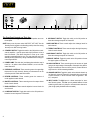
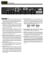
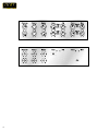
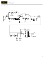
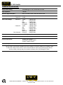
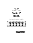
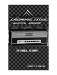
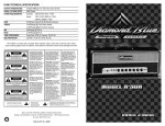
VC-120H
Vintage Club Amplifier
OWNER’S MANUAL
VC-120H Amplifier
Congratulations!
You are now the proud owner of one of the newest and most versatile tube amplifiers
available for the guitar! The CRATE VC-120H offers flexibilty and portability with two separate channels for a uniquely rich palette of tonal variety and simplicity of control over your
sound.
Your CRATE Vintage Club Series amplifier is musician-made in the U.S.A. using the
finest components available. Each unit is rigorously tested by skilled technicians and musicians to ensure that your amplifier is the best it can be!
In order to get the most out of your new amplifier, we strongly urge you to go over the
information contained in this manual before you begin playing.
And thank you for choosing
CAUTION
ATTENTION
VORSICHT
RISK OF ELECTRIC SHOCK
DO NOT OPEN
RISQUE D'ELECTROCUTION
NE PAS OUVRIR
ELEKTRISCHE SCHLAGGEFAHR
NICHT OFFENEN
CAUTION: TO REDUCE THE RISK OF ELECTRIC SHOCK,
DO NOT REMOVE COVER.
NO USER-SERVICEABLE PARTS INSIDE.
REFER SERVICING TO QUALIFIED SERVICE PERSONNEL.
ATTENTION: POUR REDUIRE D'ELECTROCUTION NE PAS
ENLEVER LE COUVERCLE. AUCUNE PIECE INTERNE N'EST REPRABLE
PAR L'UTILISATEUR. POUR TOUTE REPARATION, S'ADRESSER A UN
TECHNICIEN QUALIFIE.
VORSICHT: ZUR MINIMIERUNG ELEKTRISCHER SCHLAGGEFAHR NICHT
DEN DECKEL ABENHMEN. INTERNE TEILE KONNEN NICHT VOM
BENUTZER GEWARTET WERDEN. DIE WARTUNG IS QUALIFIZIERTEM
WARTUNGSPERSONAL ZU UBERLASSEN.
THIS EQUIPMENT HAS BEEN DESIGNED AND ENGINEERED TO PROVIDE SAFE AND RELIABLE OPERATION. IN ORDER TO PROLONG THE LIFE
OF THE UNIT AND PREVENT ACCIDENTAL DAMAGES OR INJURY, PLEASE FOLLOW THESE PRECAUTIONARY GUIDELINES:
CAUTION: TO REDUCE THE RISK OF ELECTRIC SHOCK, DO NOT OPEN CHASSIS; DO NOT DEFEAT OR REMOVE THE GROUND PIN OF THE
POWER CORD; CONNECT ONLY TO A PROPERLY GROUNDED AC POWER OUTLET.
WARNING: TO REDUCE THE RISK OF FIRE OR ELECTRIC SHOCK, DO NOT EXPOSE THIS EQUIPMENT TO RAIN OR MOISTURE.
CAUTION: NO USER-SERVICEABLE PARTS INSIDE. REFER SERVICING TO QUALIFIED SERVICE PERSONNEL.
CAUTION: THIS UNIT IS CAPABLE OF PRODUCING HIGH SOUND PRESSURE LEVELS. CONTINUED EXPOSURE TO HIGH SOUND PRESSURE
LEVELS CAN CAUSE PERMANENT HEARING IMPAIRMENT OR LOSS. USER CAUTION IS ADVISED, AND EAR PROTECTION RECOMMENDED IF
UNIT IS OPERATED AT HIGH VOLUME. THE CHART BELOW SHOWS THE U.S. GOVERNMENT’S OCCUPATIONAL SAFETY AND HEALTH ADMINISTRATION (OSHA) REGULATIONS WHICH WERE IN EFFECT AT THE TIME OF THIS PUBLICATION FOR PERMISSIBLE NOISE EXPOSURE, PER
29CFR1910.95, TABLE G-16:
SOUND LEVEL DBA, DURATION PER DAY
SLOW RESPONSE
IN HOURS
90
8
92
6
95
4
97
3
100
2
SOUND LEVEL DBA,
SLOW RESPONSE
102
105
110
115
DURATION PER DAY
IN HOURS
1 - 1 1/2
1
1/2
1/4 or less
ACCORDING TO OSHA, ANY EXPOSURE IN EXCESS TO THESE AMOUNTS LISTED ABOVE COULD RESULT IN SOME HEARING LOSS.
EXPLANATION OF
GRAPHICAL SYMBOLS:
2
"DANGEROUS VOLTAGE"
= "DANGER HAUTE TENSION"
"GEFAHLICHE SPANNUNG"
"IT IS NECESSARY FOR THE USER TO REFER TO THE INSTRUCTION MANUAL"
= "REFERREZ-VOUS AU MANUAL D'UTILISATION"
"UNBEDINGT IN DER BEDIENUNGSANLEITUNG NACHSCHLAGEN"
VC-120H Amplifier
TABLE OF CONTENTS:
Features . . . . . . . . . . . . . . . . . . . . . . . . . . . . . . . . . . .3
The Front Panel Controls and Their Use . . . . . . . . . . .4
The Rear Panel . . . . . . . . . . . . . . . . . . . . . . . . . . . . .5
Some Suggested Settings . . . . . . . . . . . . . . . . . . . . .6
System Block Diagram . . . . . . . . . . . . . . . . . . . . . . . .7
Technical Specifications . . . . . . . . . . . . . . . .back cover
Features:
• All tube operation
• Two completely independent channels with individual gain and tone controls
• Channel switching from the front panel or footswitch (supplied)
• Individual reverb return controls for each channel
• Effects Loop for virtually noise-free connection of your favorite effect(s) – controllable
by a footswitch (supplied)
• Specially designed paper bobbin output transformer for a true “vintage” sound
• Durable tolex® covering and special cosmetic treatments for a unique stage appearance
3
1
2
3
4
5
6
7
8 9 10
11 12 13 14
15
16
The Front Panel Controls and Their Use:
1. POWER SWITCH: Toggle this switch to the ON position to turn on
the amplifier.
9. MID BOOST SWITCH: Toggle this switch to the ON position to
boost the midrange response of Channel B.
NOTE: Always turn the power switch ON FIRST, OFF LAST. Use the
Standby switch (toggled to the Standby position) when first turning
the amp on as well as during breaks.
10. MID CONTROLS: These controls adjust the midrange levels for
each channel.
2. STANDBY SWITCH: Toggle this switch to the ON position to activate the amplifier – once the power switch (#1) has been on for at
least 30 seconds. (This allows the tubes to come up to a safe
operating temperature before use.) The amp should be set in the
Standby mode (switch down) during extended breaks to help promote longer tube life.
3. POWER LAMP: This dual color jewel lamp glows when the amp is
turned on – an amber color indicates Channel A, a red color indicates Channel B.
4. PRESENCE CONTROLS: These controls govern the upper-high
frequencies for each channel, allowing an enhancement to the
sound beyond the Treble and Mid controls.
5. REVERB CONTROLS: These controls govern the amount of
reverb applied to each channel.
6. MASTER CONTROLS: These controls govern the output volume
levels of each channel.
7. BASS CONTROLS: These controls adjust the low end levels for
each channel.
8. LOW BOOST SWITCH: Toggle this switch to the ON position to
boost the low end response of Channel A.
4
11. TREBLE CONTROLS: These controls adjust the high frequency
levels for each channel.
12. MID BOOST SWITCH: Toggle this switch to the ON position to
boost the midrange response of Channel A.
13. BRIGHT SWITCH: Toggle this switch to the ON position to boost
the upper register of Channel B.
14. GAIN CONTROLS: These controls govern the amount of signal
going to the output stage of the amplifier. Channel A Gain offers a
range of sounds from clean to a bluesy crunch; Channel B from a
slight crunch to full tilt screaming distortion.
15. CHANNEL SWITCH: Toggle this switch to the desired channel: up
for Channel A, down for Channel B. A footswitch also may be used
to select channels, in which case this switch is bypassed – see
#17, rear panel.
16. INPUT JACKS: The High input is a direct connection for “standard” electric guitars. The Low input is padded 6dB and is best
suited for guitars with “hot” pickups or on-board active electronics.
(Use a high quality shielded instrument cable.)
VC-120H Amplifier
EFFECTS LOOP
FOOTSWITCH
SEND
RETURN
SPEAKERS
EFFECTS LEVEL
120 WATTS RMS
SPEAKER IMPEDANCE MUST MATCH
SELECTED AMPLIFIER IMPEDANCE
BIAS
IMPEDANCE
SELECTOR
8
R
S
T
R
EXT.
T
0
S
16
MAIN
10
(USE FIRST)
TIP = CH. SELECT
RING = LOOP ON/OFF
SLEEVE = GROUND
T.P.
ADJUST
100 / 120 VAC
220 / 240 VAC
T5A SLO BLO
T2.5A SLO BLO
MODEL: VC-120H
SERIAL: VC-120H0000001
MODEL
VC-60
LINE:
V~
Hz
WATTS:
MAX
SERIAL #
A
NOTE:
BIAS ADJUSTMENT
SHOULD BE PERFORMED
ONLY BY QUALIFIED SERVICE
TECHNICIAN.
TO REPLACE THE RISK OF FIRE,
REPLACE FUSE WITH SAME TYPE
AND RATING.
MADE IN THE U.S.A. BY SLM ELECTRONICS
1400 FERGUSON AVENUE, ST. LOUIS, MO 63133
AC LINE IN
UTILISER UN FUSIBLE DE RECHANGE
DE MEME TYPE.
CAUTION
RISK OF ELECTRIC SHOCK
DO NOT OPEN
AVIS: RISQUE DE CHOC ELECTRIQUE. NE PAS OUVRIR.
TO REDUCE THE RISK OF FIRE OR ELECTRIC SHOCK,
WARNING: DO
NOT EXPOSE THIS APPLIANCE TO RAIN OR
MOISTURE.
17
18
19
20
21
22
23
24
25
The Rear Panel:
17. FOOTSWITCH JACK: Connect the supplied two button
footswitch for control of channel switching and the effects
loop on/off. The tip of the jack is for channel switching; the
ring is for effects. When a footswitch is connected here, the
front panel channel select switch is disabled.
18. EFFECTS LOOP SEND JACK: Connection to an external
effects device is made via this jack. Connect a shielded
instrument patch cord from the send jack to the input jack
of the effect. The send jack also doubles as a "preamp out"
jack, to feed a post-eq signal to a mixing board, recording
console or external amplifier.
NOTE: Effects loop operation is parallel with the signal
path. Mix controls on the effects should be set to 100% (full
wet). If no effects are connected to the Effects Loop, the
Effects Level control (#20) acts as an extra volume boost
which can be activated by the footswitch. For the best signal to noise ratio when NOT using the effects loop, keep
the Effects Level control (#20) set to “0”.
19. EFFECTS LOOP RETURN JACK: Connection from an
external effects device is made via this jack. Connect a
shielded instrument patch cord from the output jack of the
effect to the return jack. The return jack also doubles as a
"power amp in" jack, to feed a line-level signal directly into
the internal power amp. This is useful when "slaving" two
amplifiers together. When using in this mode (slaving),
make sure the front panel Master volume controls are all
the way down (at “0”).
20. EFFECTS LEVEL CONTROL: Use this knob to set the
input level of the signal from the Effects Loop Return jack
(#19). The Effects Loop Send level is adjusted by the
Master volume controls (#6).
22. IMPEDANCE SWITCH: For the best performance and
least strain on the amp, you MUST match the amp’s impedance to that of your speaker cabinet(s). Set the selector
switch to the 8 or 16 ohm position, depending on the total
impedance of your cabinets. The chart below can help you
determine that impedance based on the following combinations of speakers connected in parallel.
CAB IMP.
16 ohms
32 ohms
32 ohms
# OF CABS
2
2
4
TOTAL IMP.
8 ohms
16 ohms
8 ohms
23. BIAS ADJUST / BIAS TEST POINT: For qualified
Service Personnel only! (All others please just ignore
these internal Bias adjustment potentiometers.)
24. FUSE: This fuse protects the amplifier against damages
caused by overload conditions in the unit. If the fuse blows,
replace it only with the same size and type as indicated on
the rear panel. If the fuse blows continually, the line voltage
may be incorrect, or the amp may need servicing.
25. AC LINE IN: Firmly plug the female end of the supplied
power cord into this socket, pushing it in until it is fully seated. Plug the male end of the cord into a properly grounded
AC outlet of the correct voltage. DO NOT DEFEAT THE
GROUND PIN OF THE AC PLUG! Use only the supplied
power cord. If the amplifier is to be used outside of the
United States, see your authorized Crate dealer for information about alternate line cords and power converters if
needed.
21. SPEAKER JACKS: Connect the amplifier to your speaker
cabinet(s) via these jacks, using heavy-duty speaker
cables (not instrument patch cords). Use cabinets rated at
8 ohms or higher, in combinations which never create a
load lower than 8 ohms. Make sure the Impedance switch
(#22) is properly set. Always use the MAIN speaker jack
first, then connect to the EXTENSION jack if using more
than one cabinet.
5
6
VC-120H Amplifier
System Block Diagram:
TRBL
HI
INPUT
STAGE
MID
BASS GAIN
GAIN
STAGE
CH. A
MID
LOW
BOOST BOOST
GAIN
STAGE
CH. A
MSTR
VOL.
CH. B
CH. B
TRBL
LOW
MID
EFFECTS
RETURN
BASS
TONE
SHAPING
GAIN
CONTROL
GAIN
STAGE
SEND RTRN
GAIN
STAGE
MSTR
VOL.
EFFECTS
DRIVER
EFFECTS
LEVEL
MID
BOOST
BRIGHT
OUTPUT
STAGE
OUTPUT
TRANSFORMER
DRIVER
MAIN
SPEAKER
REVERB
SEND
EXTENSION
SPEAKER
REVERB
RETURN
REVERB
LEVELS
PRESENCE
7
VC-120H Amplifier
TECHNICAL SPECIFICATIONS:
Output Power Rating
120W RMS @ 5% THD, 16 ohm load, 120 VAC
Input Impedance
1 M ohm
Maximum Signal Accepted
0dB: 1.5V peak to peak; -6dB: 2.8V peak to peak
Gain
Channel A:
Channel B:
68dB
100dB
Tone Control Range
Channel A:
Treble:
Mid:
Bass:
Mid Boost:
Low Boost:
Treble:
Mid:
Bass:
Bright:
Mid Boost:
Presence:
Channel B:
Both Channels
16dB @ 5kHz
8dB @ 700Hz
10dB @ 50Hz
12dB @ 800Hz
13dB @ 100Hz
16dB @ 2.5kHz
6dB @ 800Hz
22dB @ 150Hz
10dB @ 3kHz
8dB @ 800Hz
4dB @ 10kHz
Effects Send
2.1V RMS @ full power output
Tube Type
Preamp: (1) 12AU7, (4) 12AX7; Power Amp: (4) 6L6GC/EL34
Power Requirements
120VAC, 60Hz, 400VA
100/115VAC, 50/60Hz, 400VA
230VAC, 50/60Hz, 400VA
Size and Weight
12-1/2” H x 27” W x 9-1/2” D, 47 lbs
The VC-120H is covered with a durable black Tolex® material. To keep the cabinet in top condition, wipe
it clean with a damp lint-free cloth to remove dirt and road film. Never spray cleaning agents directly
onto the cabinet, and stay away from abrasive cleansers which could damage the finish.
Crate continually develops new products, as well as improves existing ones. For this reason, the specifications and information in this manual are subject to change without notice.
www.crateamps.com
©1998 SLM ELECTRONICS • A division of St. Louis Music • 1400 Ferguson Avenue • St. Louis, Mo 63133
P/N 47-271-02 • 08/98