1
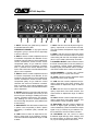
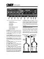
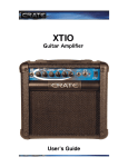
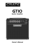
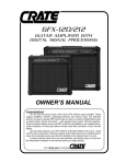
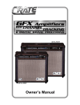
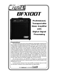
GFX-65
GUITAR AMPLIFIER WITH
DIGITAL SIGNAL PROCESSING
USER’S GUIDE
Congratulations!
You are now the proud owner of the Crate GFX-65 guitar amplifier. This rugged
amplifier delivers serious clean and distorted sounds through its premium 12” Crate
Custom speaker. An easy to operate DSP section lets you dial in a variety of digital
effects such as delay, flange, chorus and reverb – with separate level control. Channel
selection and Crate’s exclusive Shape circuit are controllable by the supplied two-button
footswitch. An insert jack allows virtually noise-free connection of your favorite effects.
Like all Crate products, your GFX-65 is designed by musicians and built using only
the best components. Extensive testing at the hands (and ears) of skilled technicians
and musicians insures you that this amplifier is the absolute best it can be.
In order to get the most out of your new amplifier, we strongly urge you to read this
user’s guide before you begin playing.
And thank you for choosing
GFX-65 Amplifier
1
2
3
4
5
1: INPUT: Connect your guitar here by means of
a shielded instrument cable.
OVERDRIVE CHANNEL: A high gain channel
designed to give you sounds from a slight edge
to serious overdrive.
2: GAIN 1: Use this control to adjust the amount
of moderate compression and distortion for the
Overdrive channel. With the control rotated fully
counter clockwise the sound will have a thick
compressed quality. As you rotate the control
clockwise the amount of distortion increases.
Gain 1 produces less intense distortion than
Gain 2 and is active when the Gain Select switch
(#5) is in the out position.
3: GAIN 2: Use this control to adjust the amount
of intense compression and distortion for the
Overdrive channel. With the control rotated fully
counter clockwise the sound will have a thick
compressed quality. As you rotate the control
clockwise the amount of distortion increases.
Gain 2 produces more intense distortion than
Gain 1 and is active when the Gain Select switch
(#5) is depressed.
4: SHAPE: Working in conjunction with the Gain
2 control, rotate the Shape control until you find
the sound you’re looking for. Rotating the control
counter clockwise enhances the mid frequencies. Rotating the control clockwise enhances
the low and high frequencies. (Only affects Gain
2 when active.)
6
7
8
9
10
7: HIGH: Use this control to adjust the high frequency output level of the Overdrive channel.
This control allows an adjustment range of 10dB
at 10kHz.
8: LEVEL: Use this control to adjust the output
volume level of the Overdrive Channel. Use this
control along with the Gain and Shape controls
(#2, 3 & 4) to create a wide variety of sounds.
9: CHANNEL SELECT: Use this switch to select
the Clean channel (switch in the out position) or
the Overdrive channel (switch depressed). A
footswitch (#18) overrides this switch. The adjacent LEDs indicate which channel is selected.
CLEAN CHANNEL: A normal gain channel
designed to give you crystal clear sounds.
10: LEVEL: Use this control to adjust the output
volume level of the Clean Channel.
11: LOW: Use this control to adjust the low frequency output level of the Clean channel. This
control allows an adjustment range of 22dB at
80Hz.
12: MID: Use this control to adjust the mid frequency output level of the Clean channel. This
control allows an adjustment range of 14dB at
600Hz.
13: HIGH: Use this control to adjust the high frequency output level of the Clean channel. This
control allows a range of 28dB at 10kHz.
5: GAIN SELECT: Use this switch to select Gain
1 (switch in the out position) or Gain 2 (switch
depressed). A footswitch (#18) overrides this
switch.
14: DSP LEVEL: Use this control to adjust the
amount of digital signal processing. With the
control rotated fully counter clockwise the output
signal is “dry” (no effect). As you rotate the control clockwise the amount of effect increases.
6: LOW: Use this control to adjust the low frequency output level of the Overdrive channel.
This control allows an adjustment range of 11dB
at 80Hz.
15: DSP MODE: Use this control to select
thedesired digital effect(s). Each category and
its central location is called out (delay, flange,
etc.) by the markings around the control..
GFX-65 Amplifier
11
12
13
14
15
There are two variations per effect, as follows:
•
•
•
•
•
•
•
•
•
•
Slapback delay
Long delay w/regeneration
Light Flange
Heavy Flange
Slow Chorus
Fast Chorus
Chorus w/small room reverb
Chorus w/large room reverb
Small room reverb
Large room reverb
16: INSERT: Use this jack to connect an external effects device to the amplifier. Use a stereo
1/4” male Y-cord: ring = send, tip = return, sleeve
= ground. See the illustration to the right for
more information.
17: EXT. SPEAKER: Use this jack to connect an
extension speaker cabinet to the amplifier. This
jack is wired in series with the internal speaker.
18: FOOTSWITCH: Use this jack to connect a
two-button footswitch to the amplifier for remote
control of the Channel Select and Gain Select
settings.
16
17
18 19
20
22: FUSE (rear panel, not shown): The fuse
protects the amplifier against damages caused
by power overload conditions. If the fuse fails,
replace it only with the same size and type fuse.
If the fuse fails repeatedly check the AC source;
if it’s okay, contact your Crate dealer for service
information.
Connecting to the Insert jack:
The Insert jack (#16) lets you patch external
effects into the amplifier just prior to its power
amp stage. Use Crate’s STP201, STP202 or
STP203 stereo-to-mono Y-cord or an adapter
such as Crate’s YPP117 and 2 1/4” mono signal
cables to connect to the effect as shown below.
Stereo-to-mono Y-cord:
to Insert
jack
TIP
RING
SLEEVE
(STP201, 3'
STP202, 6'
STP203, 9')
Y-adapter and 2 cables:
RETURN
SEND
GROUND
TIP
RING
SLEEVE
to Insert
jack
(YPP117)
19: POWER ON LED: This LED illuminates
when the amplifier is turned on.
RING
TIP
RING
21. POWER CORD (rear panel, not shown):
The grounded power cord should only be
plugged into a grounded power outlet that meets
all applicable electrical codes and is compatible
with the voltage, power and frequency requirements stated on the rear panel. Do not attempt
to defeat the safety ground connection!
TIP
20: POWER SWITCH: Use this switch to turn
the amplifier on (top of the switch depressed) an
off (bottom of the switch depressed).
(1/4"-TO-1/4"
MONO SHIELDED
CABLES)
to
effect
"OUT"
jack
to
effect
"IN"
jack
External Effect
to
effect
"OUT"
jack
to
effect
"IN"
jack
External Effect
GFX-65 Amplifier
GFX-65 TECHNICAL SPECIFICATIONS
Output Power Rating
Speaker Size and Rating
Input Impedance
Maximum Input Signal Level Accepted
Total System Gain
65 watts RMS @ 5% THD 8 ohms minimum external load
(1) Custom Design 12”, 8 ohms
470k ohms
7 volts, peak-to-peak
Overdrive Channel: 110dB all controls @10, Gain 2; 88dB Gain 1
Clean Channel: 58dB all controls @10
11dB Range @ 80Hz
Proprietary Circuit
10dB Range @ 10kHz
22dB Range @ 80Hz
14dB Range @ 600Hz
28dB Range @ 10kHz
120 VAC, 60Hz, 90VA
100/115VAC, 50/60Hz, 90VA
230VAC, 50/60Hz, 90VA
17-1/2” H x 20” W x 11” D, 34 lbs.
Overdrive Channel:
Low Control:
Shape Control:
High Control:
Clean Channel:
Low Control:
Mid Control:
High Control:
Input Power Requirements
Cabinet Size and Weight:
The GFX-65 is covered with a durable black Tolex material: wipe it
clean with a lint-free cloth. Never spray cleaning agents onto the
cabinet. Avoid abrasive cleansers which could damage the finish.
CAUTION
PRECAUCION
ATTENTION
RISK OF ELECTRIC SHOCK
DO NOT OPEN
RIESGO DE CORRIENTAZO
NO ABRA
RISQUE D'ELECTROCUTION
NE PAS OUVRIR
WARNING: TO REDUCE THE RISK OF FIRE OR ELECTRIC
SHOCK, DO NOT EXPOSE THIS APPARATUS TO RAIN OR MOISTURE. TO REDUCE THE RISK OF ELECTRIC SHOCK, DO NOT
REMOVE COVER. NO USER-SERVICEABLE PARTS INSIDE.
REFER SERVICING TO QUALIFIED SERVICE PERSONNEL.
PRECAUCION: PARA REDUCIR EL RIESGO DE INCENDIOS O DESCARGAS
ELECTRICAS, NO PERMITA QUE ESTE APARATO QUEDE EXPUESTO A LA
LLUVIA O LA HUMEDAD. PARA DISMINUOIR EL RIESGO DE CORRIENTAZO.
NO ABRA LA CUBIERTA. NO HAY PIEZAS ADENTRO QUE EL USARIO PUEDO
REPARAR DEJE TODO MANTENIMIENTO A LOS TECHNICOS CALIFICADOS.
ATTENTION: PROTÉGEZ CET APPAREIL DE LA PLUIE ET DE L'HUMIDITÉ
AFIN D'ÉVITER TOUT RISQUE D'INCENDIE OU D'ÉLECTROCUTION. POUR
REDUIRE D'ELECTROCUTION NE PAS ENLEVER LE COUVERCLE. AUCUNE
PIECE INTERNE N'EST REPRABLE PAR L'UTILISATEUR. POUR TOUTE
REPARATION, S'ADRESSER A UN TECHNICIEN QUALIFIE.
IMPORTANT SAFETY INSTRUCTIONS
• READ, FOLLOW, HEED, AND KEEP ALL INSTRUCTIONS AND WARNINGS.
• DO NOT OPERATE NEAR ANY HEAT SOURCE AND DO NOT BLOCK ANY VENTILATION OPENINGS ON THIS APPARATUS. FOR
•
•
•
•
•
•
•
•
•
PROPER OPERATION, THIS UNIT REQUIRES 3” (75mm) OF WELL VENTILATED SPACE AROUND HEATSINKS AND OTHER AIR
FLOW PROVISIONS IN THE CABINET.
DO NOT USE THIS APPARATUS NEAR SPLASHING, FALLING, SPRAYING, OR STANDING LIQUIDS.
CLEAN ONLY WITH LINT-FREE DAMP CLOTH AND DO NOT USE CLEANING AGENTS.
ONLY CONNECT POWER CORD TO A POLARIZED, SAFETY GROUNDED OUTLET WIRED TO CURRENT ELECTRICAL CODES AND
COMPATIBLE WITH VOLTAGE, POWER, AND FREQUENCY REQUIREMENTS STATED ON THE REAR PANEL OF THE APPARATUS.
PROTECT THE POWER CORD FROM DAMAGE DUE TO BEING WALKED ON, PINCHED, OR STRAINED.
UNPLUG THE APPARATUS DURING LIGHTNING STORMS OR WHEN UNUSED FOR LONG PERIODS OF TIME.
ONLY USE ATTACHMENTS, ACCESSORIES, STANDS, OR BRACKETS SPECIFIED BY THE MANUFACTURER FOR
SAFE OPERATION AND TO AVOID INJURY.
WARNING: TO REDUCE THE RISK OF ELECTRIC SHOCK OR FIRE, DO NOT EXPOSE THIS UNIT TO RAIN OR MOISTURE..
SERVICE MUST BE PERFORMED BY QUALIFIED PERSONNEL.
OUR AMPLIFIERS ARE CAPABLE OF PRODUCING HIGH SOUND PRESSURE LEVELS. CONTINUED EXPOSURE TO HIGH SOUND
PRESSURE LEVELS CAN CAUSE PERMANENT HEARING IMPAIRMENT OR LOSS. USER CAUTION IS ADVISED AND EAR PROTECTION IS RECOMMENDED IF UNIT IS OPERATED AT HIGH VOLUME.
EXPLANATION OF GRAPHICAL SYMBOLS:
EXPLICACION DE SIMBOLOS GRAFICOS:
EXPLICATION DES SYMBÔLES GRAPHIQUES:
"DANGEROUS VOLTAGE"
=
“VOLTAJE PELIGROSO”
"IT IS NECESSARY FOR THE USER TO REFER TO THE INSTRUCTION MANUAL"
=
"DANGER HAUTE TENSION"
“ES NECESARIO QUE EL USUARIO SE REFIERA AL MANUAL DE INSTRUCCIONES.”
"REFERREZ-VOUS AU MANUAL D'UTILISATION"
Crate continually develops new products, as well as improves existing ones. For this reason, the
specifications and information in this Crate manual are subject to change without notice.
www.crateamps.com
©1997 SLM ELECTRONICS, A DIVISION OF ST. LOUIS MUSIC, 1400 FERGUSON, ST. LOUIS, MO. 63133
P/N 47-475-01 • 030603