1
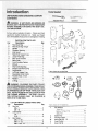
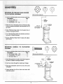
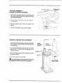
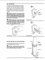
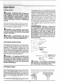
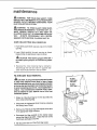
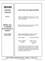
Save This Manual For
Future Reference
\
Dust CoBlection
System
Serial
Number
Model and serial number may be
found on the motor cover.
You should record both model and
serial number in a safe place for
future use.
FOR YOUR
SAFETY:
READ
DUST COLLECTION
S YS TEM
ALL
INSTRUCTIONS
CAREFULLY.
Sold by SEARS, ROEBUCK
Part No. SP5373
° assembmy
o operation
"parts
o repamr
AND CO., Chicago,
IL. 60684 U.S.A.
Printed in Taiwar_
•
• •:• •_:-•-::_:/.'-
•
•••
FULL:ONEYEAR
,.,.
WARRANTY
ON CRAFTSMAN
,,i
_.
DUST C-OLL_
If within 0ne year from the date of purchase, thls Craftsman Dust Collection System falls due to a defect in
maierlal0r workmanship; Sears wil! repair it, free of charge;
WARRANTY SERVICE IS AVAILABLE BY SIMPLY CONTACTING THE NEAREST SEARS SERVICE CENTER/
DEPARTMENTTHROUGHOUT THE UNITED STATES.
This warranty applies only while this product is used in the United States.
Thiswarranty givesyou specific legalrights, and you mayaiso haveother rights which vary from stateto state.
SEARS, ROEBUCK AND CO., D/817 WA HOFFMAN ESTATES,IL 60135
PO
TANT SAFETY INSTRUCTIO
When using your Dust Collection System, follow basic
safety precautions including the following.
WARNING" wTo
To avoid injury from accidental starting, unplug power
cord before changing or cleaning filter/dust bag or chip
bag..
reduce the risk of
Do not use without filter/dust bag and/or chip bag in
place.
fire, electric shock, or injury:
• Readand understand this owner's manual and all
labels on the Dust Collection System before operating;: Use only as described in this manual. To
avoid personal injury or damage to Dust Collection System, use only Sears Craftsman recommended accessories.:
_
Sparks inside the electrical parts, can ignite flammable
Vapors or dust. To avoid fire or explosion:
° Do not vacuum, or use this Dust Collection System
neariiammable orcombustlble iiquids, gases, gasoline or other fuels, lighter fluidi cleaners, oiFbased
paints,, natural gas;_hydrogen, or explosive dusts like
:
gust,magnes!umous_!gram
: i: _,J_um .nvthinn
ous t, o r gun Powoer;
,h_fii_ hJ,mtnn t_r _mni_in_:
• Do not va....... __, .... _,.... ........
= ....... """'_'
such as cigarettes, matches, or hot ashes.
" To avOid health hazards from vapors or dusts, do not
vacuum toxic materials;
o
Do not unplug by pulling on cord. To unplug, grasp the
plug, not the cord.
° Turn off controls before unplugging.
o Do not use with damaged cord,
your Dust Collection System
should, has missing parts, has
aged; left outdoors, or dropped
a Sears Service Center.
, n,,
,,t,, ,,^,,,_. ,, _, ,,,,,,_ .....
plug or other parts. If
is not working as it
been dropped, daminto water, return it to
,_.,,. h..,.._l.....
:..... a :dobr on cord;or pail cord: around sharp edges or
coiners: Donotrun DustCoilectionSystemovercord.
Keepcord away from heated surfaces.
• Do not handle plug of the Dust Collection System with
wet:hands.
Do not put any object into ventilation openings. Do not
vacuum with any ventilation openings blocked; keep
free of dust, lint, hair or anything that may reduce air
flow.
• Do: not use Or store near hazardous materials.
• Do not use outdoors or on wet surfaces.
" Put unit on a stable, level surface.
o
Keep hair, loose clothing, fingers, and all parts of body
away from openings and moving parts.
°
Extension cords in poor condition or that are too small
can pose fire and shock hazards. When using an
extension cord, be sure it is in good condition. See
"Extension Cords" in the "Operation" section for proper
wire sizes.
• Route vacuum hose and electric cord out of traffic
areas.
- Do not allow to be used as a toy. Close attention is
necessary when used by or near children.
• Donotleaveappliancepluggedin.
Unplug from outlet
when not in use and before servicing.
°
Connect to properly grounded outlet only.
"Grounding Instructions" on page 14.)
SAVE THESE iNSTRUCTiONS
11
,
.
Hi,
11
i|1,
(See
_
CAUTION: if usingthts Dust Collection System
to help keep airborne wood dust in heavy usage
within acceptable limits, you must regularly monitor
air borne dust andmaintain Dust Collection System
to avoid exceeding dust limits. Each application is
unique. Your maintenance schedule must, therefore, be tailored to your specific use of this Dust Collection System.
Safety is a combination of common sense, staying alert
and knowing how your Dust Collection System works.
BEFORE
USBNG THE
DUST
COLLECTION
SYSTEM:
_
BEFORE
EACH
USE:
1. inspect your Dust Collection System. if any parts
are missing, bent, or faiJ in any way, or any electrical components do not work properly, turn off the
Dust Collection System, remove switch key, and
remove power supply cord from power supply.
Replace damaged, missing or failed parts before
using the Dust Collection System again.
2. Plan your work to protect your eyes, hands, face,
ears and body.
WEAR
YOUR
WARNING: TO AVOID MISTAKESTHATCOULD
RESULT IN SERIOUS, PERMANENT INJURY, DO
NOT CONNECT POWER CORD UNTIL THE FOLLOWING STEPS HAVE BEEN SATISFACTORILY
COMPLETED:
1. Assembly, mounting and alignment.
2. Learn the function and proper use of the ON-OFF
switch.
3. Read and understand all safety instructions and
operating procedures throughout the manual.
4. Read the following labels which appear on the top
and bottom of filtration housing and sides of motor,
WARNmNG
Metal shavings
or dust can set
sawdust on fire.
Do not collect
Collect
or dust. wood
See manual
metal shavings
materials
onty.
Use
indoors
B. When cleaning collection bags, wear a dust
mask.
for details,
Risk Of electrical
shock.
in dry
area,
Do not use outdoors
or on wet
surfaces.
Sparks
can
flammable
Do
not
ignite
vapors
from
!
products,
use
around
flammabie
products.
If connected
to a circuit protected
by fuses, use time delay fuses
with this appliance,
Electrical:
120 volts, 60 Hz AC onty,
7 amp
WARNmNG
Hazardous
moving
parts
Unplug before removing
A. WEAR SAFETY GOGGLES, FORESIGHT iS
BETTER THAN NO SIGHT.
Wear sale',y
goggles, not glasses, that comply with ANSE
Z87.t (shown on label). Operaling any power
toot can result in foreign objects being tllown
into the eyes which can result in permanent eye
damage. Safety goggles are available at Sears
retail catalog stores, Use of glasses or goggles
not in compliance with ANSI Z87.1 could result
in severe injury from breakage of the eye protection.
inside
inlet guard,
Attach inlet guard before plugg ing in,
:4
AFETY
1.
KNOWYOUR
TOOL
Read and undersiarid
owner's
INSTRUCTIONS
manual
12. USESAFETY GOGGLES (Head Protection)
: :: wear safety goggles (mUstcomply with ANSI Z87.1 )
at all times., Everyday eyeglasses only have impact
resistant lenses; they are NOT safety glasses. Also.
use lace or dust mask if cutting operation is dusty,
and ear protectors (plugs or muffs)during extended
periods or operation
13. DON'T OVERREACH
Keep proper footing and balance at all times.
14. MAINTAIN TOOLS WITH CARE
Keep tools sharp and clean for best and safest
performance. Follow instructions for lubricating and
changing accessories.
15. DISCONNECT TOOLS
Before servicing, when changing accessories or attachments.
16. AVOID ACCIDENTAL STARTING
Make sure switch is in "OFF" position before plugging in.
17. USE RECOMMENDED ACCESSORIES
Consult the owner's manual for recommended
accessories.
Follow the instructions that accompany the accessories. The use of improper accessories may cause hazards.
18. NEVER STAND ON TOOL
Serious injury could occur If t he tool tips over. Donut
store materials such that it is necessary to stand on
the tool to reach them.
19. CHECK DAMAGED PARTS.
Before further use of the tool, a guard or other part
that is damaged should be carefully checked to
ensure that it will operate properly and perform its
intended function. Check for alignment of moving
parts, binding or moving parts, breakage oF parts.
mounting, and any other conditions that may affect
its operation. A guard or other part that is damaged
should be properly repaired or replaced.
20. NEVER LEAVE MACHINE RUNNING UNATTENDED
Turn power "OFF". Don't leave Dust Collection
System until it comes to a complete stop.
and labels
3tt_xed to the tOOl [:.earn its appiicalion and limitanuns as welt as its(specffic potenl.iat hazards pec,
uafiar tolhis tOoL
2, _ GROUND THE TOOL
3.
This Io01 is equipped with an approved 3-conductor
cord and a 3prong
grounding type plug to tit the
proper grounding type receptacle
The green con
ductor in the cord is the grounding wire
Never
connect the green wire 1o a live terminai.
KEEP GUARDS
tN PLACE
4.
- in working Order. and in proper adjustment
and
alignment:
REMOVE
ADJUSTING
KEYS AND WRENCHES
5.
6.
Form habit of checking to see that keys and adjust.
ing wrenches are removed from loci before turn_ng
qton.
KEEP WORK AREA CLEAN
Cluttered areas andbenchesfnvite
accidents. Floor
must not be slippery due to wax or sawdust,
AVOID DANGEROUS
ENVIRONMENT
Don't use power tools in damp or wet locations or
expose them to rain. Keep work area welt lighted.
Provide adequate surrounding work space.
7. KEEP CHILDREN
AWAY
B,
A!I visitors should be kept a safe distance
area,
MAKE WORKSHOP
CHILD*PROOF
9.
-- with padlocks,
master switches,
starter keys.
USE PROPER SPEED
from work
or by remowng
This loci will do the job better and safer when oper_
ated atthe proper speed.
10; USE RIGHT TOOL
Don't force tool or attachment
itwas not designed.
1t. WEAR PROPER APPAREL
:FOR: POWER TOOLS
to do a job 1or which
Do not wear loose clothing,
gloves, neckties or
jewelry (rings, wristwalches)
to gel caught in moving
pans. Non-slip footwear =s recommended.
Wear
protective hair covering to contain long hair. Roll
long sleeves above the elbow.
4
........
iiiiii ii ,i
,i,
introduction
The Craftsman Dust Collection System is specifically
designed to capture sawdust and wood chips at the
source. The fine dust is filtered by the upper bag while
heavy particles settle in the lower bag for easy removal.
Do not use as a vacuum.
_
quency of slatic shocks in your home, the best remedy
is to add moisture to the air with a console or installed
humidifier.
The safety information in this manual is highlighted by
the following safety alert symbol.
CAUTION: The blower housing containsa high
speed fan bgade that can amputate fingers, grab
loose clothing and neckties, or prope_ dust at high
velocities. DO NOT OPERATE WITHOUT ALL PARTS
IN PLACE.
]'he following signal words are used to indicate the lever
of risk.
Do not attempt to clean, remove dust bags or service
unit while in operation. Disconnect from power
source.
_
This Dust Collection System is intended for either corn*
mercial or household use.
_
IMPORTANT
Please
NOTE
Means that if the safety information
WARNING:
Means that ifthe safety information
is not followed, someone could be seriously injured or
killed.
Read Carefully
Static Shocks Are Common - in dry areas or when the
relative humidity of the air is low. To reduce the fie-
TABLE
ITEM
DANGER:
is not followed, someone will be seriously injured or
killed.
_,
CAUTION:
Means that if the safety information
is not followed, someone may be injured.
OF CONTENTS
PAGE
ITEM
WARRANTY INFORMATION .................................... 2
IMPORTANT SAFETY INSTRUCTIONS ................... 2
GENERAL SAFETY INSTRUCTIONS FOR
POWER TOOLS .................................................... 4
INTRODUCTION ........................................................
5
Unpacking and Checking Carton Contents ............ 6
ASSEMBLY ................................................................
7
Mounting Front Pivoting Casters ........................... 7
Mounting Rear Fixed Casters ................................ 7
Mounting Inlet Guard ............................................ 7
Mounting Support Legs .......................................... 8
Mounting Leg Bracket ............................................ 8
Mounting inlet Bracket ........................................... 9
Mounting Base Plate .............................................. 9
Mounting Filter/Dust Bag Holder .......................... i0
Mounting Handle to Filtration Housing ................. 10
Chip Bag Assembly ............................................. 11
PAGE
Filter/Dust Bag Assembly ....................................
OPERATION ............................................................
Attaching Accessories to inlet Guard ..................
Connecting Dust Collection System to
Power Source ...................................................
OnlOff Switch ......................................................
Moving Dust Collection System ...........................
Power Supply ......................................................
Grounding Instructions ........................................
Extension Cords ..................................................
MAINTENANCE .......................................................
Chip Collecting Bag Removal ..............................
Filter/Dust Bag Removal ......................................
Motor ...................................................................
TROUBLESHOOTING .............................................
REPAIR PARTS ......................................................
5
11
12
12
12
13
13
t4
14
14
t5
t5
15
16
16
18
Tools Needed
I_NPAC_KiR_ i_::_
_HECKING
CARTON
€ONTENTSI!
Adjustable Wrench
Screwdriver
......
Key
A _;
B
C
D
E _
i
CARTON CONTENTS LISTf
Descrlptlon
Qty,
FiltedDust Bag ........................................... 1
Fitter/Dust Bag Hanger ........................... 1
Handle. ...................................................... 1
Filtration Housing ....................................... 1
inlet Guard ................................................. t
F : ::Right Side Support Leg ............................. 1
G
Loose Parts Bag .....................................
1
H
Rear Fixed Casters .....................................
I
Base Plate ........:...................... ...........:: ........ 1
J
K
L:
M
N
O :
P
Q
R
Front Pivoting Casters ............................... 2
Manual ....... :..:...........................................
1
Chip Collecting Bag ............................... .... !
Bracket and Inlet Clamp ....................... ..... 1
Leg Bracket: .....:...... .................................. .. 1
Left Side Support Leg ................................ 1
Adjustable Band Clamp
......................
1
Flexibte Hose, 4 Inch .: ........................
_._1
Adapter .::__.,,_::_::.
................................. :.._.::1
S
O:Ring _,:.....:,......_......................
TION SYSTEM
IN DURING
ASSEMBLY
!- Items shown are not actua! size
1
CAN RESULT
IN ELECTRICALSHOCK
ORYOUR FINGERS, HAND,
OR ARM BEING CUTOFF FROM FAN BLADE CONTACT. DO NOT PLUG IN THE COLLECTOR
AT ANY
TIME DURING ASSEMBLY.
THE DUST COLLECTION SYSTEM
SHOULD
ONLY BE PLUGGED
tN
WHEN IT IS TO BE USED.-
LIST OF PARTS IN LOOSE PARTS BAGf
Description
Qty.
Hex Nut
M6x 1 .................................................... 5
3/8- 16 .................................................. 2
R
Lockwasher
1/4...:...: ................................................... 9
5116 ........................................................
8
S
Hex Screw
M6 x 1-30 ::.:.._;.:.._,.__....i:........
...... ...... _.... 4
Key
Q
t
Items
T
U
v
W
x
Y
shown
_tfe not
actual
_,ize
Flat Washer
1/4 x 1/2 .................................................
5/16 x 11/16 x1,16 ...........................
3/8 x 3/4 ...............................................
Switch Key .................................................
Pivolin.q Caster ...........................................
Acorn Nut 3/8 - 16 ......................................
Fixed Caster ...............................................
Hose Clamp
...............................................
7
18
4
1
2
2
2
2
assembmy
MOUNTING
FRONT PRVOTING CASTERS
1, Locate the following items from the loose parts bag:
Description
Qty.
A Pivoting Casters ................................... 2
B Hex Nuts* (3/8 - 16) .............................. 2
C Flat Washers* (3/8 x 3/4) ...................... 4
D Acorn Nuts*, ......................................... 2
E Base Plate ............................................ 1
2. Screw a hex nut completely
on the Caster
A
E
0*
* }terns are shown actual size
bolt.
ACORN
3. Position flat washeron top of previously installed hex
nut and slip the Caster bolt through the hole on front
of Base Plate. Position secondflat washeron the bolt.
FLAT
NUT_,
WASHER
4. Screw the Acorn Nut on the bolt securely with an
adjustable wrench.
5. Tighten the hex nut securely against the base plate.
6, Repeat steps 2 - 5 on opposite side.
CASTER
i
MOUNTING
REAR
FIXED
CASTERS
1. Locate the following items from the loose parts bag
Descrlptlon
Qty.
A Fixed Casters ....................................... 2
B Flat Washers* (1/4 x 1/2). ..................... 4
C Lockwashers* (1/4) .............................. 4
D Hex Head Screws* (M6 x 1 - 12) .......... 4
C_
A
B'_
* Items are shown actual size
BASE PLATE
(REAR)
_HEX
SCREW
2. Position Fixed Casterunder rear of Base Plate so that
holes on Caster bracket and Base Plate line up.
3. Install hex screw, lock washer and flat washer as
shown, Tighten securely using an adjustable wrench
FLAT WASHER
F.,_ED
4. Repeat steps 2 and 3 on opposite side.
i
MOUNTnNG
CASTER
•
iNLET GUARD
1. Locate the following items from the loose parts bag:
Description
Qty
A Flat Washers* (5/16 x 11/16 xl/16) ..... 4
B Hex Screws* (M8 x 1.25 -12) ............... 4
C Lockwashers ° (5/16) ............................. 4
2. Locate the Filtration Housing and Inlet Guard.
'H,.,HL
L•
.I,
,
I
HI,
* Itemsareshown
I
c
A
,IHUIL._
*V
actual
size
::
4i Support the opposite side of Filtration Housingw_th a
b[()ck of wood_
A;:Ptace:O÷Ring in relief of Inlet pipe (See page!8)
5.: Position Inlet Guardin tine with the threaded holes On
the base of the Filtration Housing.
NOTE: Makesureinlet
Guard is pointing to rear of
machine_
6. Place Iockwasher and flat washer on hex screw and
insert through the holes of the Inlet Guard into the
threaded holes of the Filtration Housing as shown.
7. Complete the process for the other three holes using
same method.
DO NOT SECURE SCREWS AT THIS TIME.
MOUNTING
SUPPORT
LEGS
1. Eocate the following items from the loose parts bag:
Descrlption Qty.
A Flat Washers* (5/16 x 11/16 x 3/32) ..... 4
B Hex Screws *(M8 x 1.25 - 12) ......... ...... 4
..... C Lockwashers* (5/16) ............................. 4
_
CAUTION:
from fan blade:
A
C
B
" Items are shown actual size
To avoid Injury, keep hands away
LEG
3. Place: lockwasher and flat washer on hex screw and
insert: through the holes in the Support Leg and
secure to the threaded holes inthe Filtration Housing
as shown,
SUPPOR.r
FLAT
WASHER
.\_b,,._
/
.EX
SCREW
_/HEX
LEG
BRACKET
I]
SCREW
LOCKWASHER
WASHER
____J_"FLA'r
4, Use same method to attach Right Support Leg.
5. Secure hex screwswiththe
MOUNTING
LEG
use of adjustable wrench.
IMPELLER
BRACKET
1. Locate the following items from the loose parts bag:
Description
Qty.
A Flat Washers* (5/16x 11/16 x 3/32) ..... 4
B Hex Screws* (MS x 1.25 - 12) ............... 4
MOTOR
/
BLOCKS
OF WOOD
2i Insert LegBracket between the Support Legs and
slide against:the angied fiange of theLeg.
NOTE: i Make _re :h01es in Leg Bracket align with
flange of Leg Support and attach to threaded hole of
BrackeL
3. Place flat washer on hex Screw, insertthro ugh angled
4: Repeat steps 2 and 3 using same process on ,other
three holes.
..........
L
IIIILui_
MOUNTING
LIIIiiiiiiiiiiiiijljl iiii, iii ii i ii
ii
INLET BRACKET
1, Locate the following items from the loose parts bag:
Description
Qty.
A Flat Washers* (5/16x 11/16xl/!6)
..... 2
B Hex Screws* (M8 x 1.25 - 12) ............... 2
C Flat Washers *(1/4 x 1/2) ...................... 2
D Hex Screws* (M6 x 1 - 12) ................... 2
A
c
R
D
* Items are shown actual size
2, Insert Inlet Bracket between relief flange of Inlet
Guard and against inside edge of angle flange on
Support Leg. Make sure both holes on Bracket align
with similar holes on Leg Support.
3. Place 5/16 flat washer on hex screw, insert through
Leg hole and attach to threaded hole of Bracket,
4. Repea! same process for other hole and secure with
use of adjustable wrench.
5. Attach Fixed Clamp as shown, by plac}ng flat washer
on hex screw, insert hex screw through hole of Fixed
Clamp and attach to threaded hole of /nfet Guard
Bracket.
6. Repeat step 5 to attach other screw below Inlet
Guard.
7. Tighten all screws on Legs, Inlet Guard, and Filtration
Housing secu rely,
MOUNTING
BASE PLATE
1. Locate the following items from the loose parts bag:
Description
Qty.
A Flat Washers* (5/I_6x 11/16xl/16) ..... 4
B Hex Screws* (M8 x 1.25 - 12) ............... 4
A
* Items are shown actual size
B
F_XED CASTERS
2. Attach Base Plate to Leg Supports by flipping base
upside down, aligning holes on both Leg Supports.
3. Place flatwasher on hex screw, insertthrough hole of
Leg and attach to threaded holes in Base Plate as
shown.
_
"- _,._--
FLA'[
WASHER
_:f -I J_ A_HEx SCREW
_, _"ill
4, Repeat same process for other three holes and
secure with adjustable wrench.
iF" _
!i
_
_
LEa
_
SUPPORT
5. With the assistance of another person, carefully flip
the Dust Collection System right side up.
ii
9
A
AG HOLDER
* Items are shown actual size
i i
1_ LoCate the foUowing items from the loose parts bag:
Description
Qty.
.....A Hex Nut* (M6 X 1) ................................ 1
B Lockwasher* (1/4) ........................... ..:: 1
C Flat Washer* (1/4x 1/2) ....................... 1
FILTER/
DUST BAG
HOLDER
2_ Attach hexnut to threaded portion of Filter/Dust Bag
Holderand place lockwasher and flat washer on nut
as shown.
HEX N UT_._
LOCKWASH ER _e=
FLAT WASHER "-'''_
/"
3, Insert Filter/Dust Bag Holder into threaded hole of
Filtration Housing as shwon.
4_ Turn Filter/DustBag Holderrod clockwise until nut is
secured to Filtration Housing.
5: Secure Fitter/Dust Bag Holder in place with adjustable wrench.
1. Locate
thefollowingDescription
items fromtheioose
pa_bag:
C
A
A HexScrews* (M6x1;25) .................... _4
B Lockwashers* (1/4'_dia.) ....................... 4
C HexNuts* (M6xl)
...........................
4
* Itemsareshownactualsize
HAN D L E
2. Attach the ends of the Handle to the ReliefFlangeson
the side of Filtration Housing as shown.
FILTER/
DUST BAG
HOLDER
FILTRATION
HOUStNG
3: lnsert hex screw through the Handle and Flange.
HEX NUT "-'_
4. Attach the lockwasher and the hex nut to the screw
and tighten.
HEX
REUEF
5: Repeat process for all four holes and secure with
adjustable wrench.
10
/
F_LTRATION
HOUSING
SAWDUST CHUTE
EXTENSION
CHiP BAG ASSEMBLY LOWER FiLTRATiON HOUSING
1. Insert lower Chip Bag by tilting the Metal Reinforced
Bandat an angle and position it through the hole inthe
lower Filtration Housing.
2. Tuck one side of the Band under the Sawdust
Chute Extension.
3. Allow the opposite side to rest on the ridge of the
opening.
4. Tug on the Chip Bag to insure proper seating,
UPPER FILTER/DUST
BAG ASSEMBLY
1. Disconnect the Adjustable Band Clampand insertthe
end through the loops provided at the opening of the
Filter/Dust Bag.
FILTER/
DUST BAG
HOLDER
2, Invert the Filter/Dust Bag and slip the open end of the
Bag over the 1" Relief on the top opening of the
Filtration Housing.
FILTER/
DUST BAG
HANDLE---_
3, Secure the Bag by adjusting the rectangular barto the
fourth set of hooks.
RELIEF /
4. Pull the lever tight until it seats itself.
_
CAUTION: Make sure the opening of the bag is
ADJUSTABLE
BAND CLAMP
tight against the relief so dust will not escape.
tl
ii:i;ii!ii!iiii!iiiiii i i!i !iiI'Hiiii: :
/
i
ThliS _Dust!i¢olie_ion System i!s designed to be corn
netted directly t0:thewoodwOrking machines. Pieasel
useoniythel_artS
provided for maximum effJctency:
4!!IDiameterx :_4)" Hose_ PVC Vulcanized rubbe_
with wire reinforcement and 2- 4'_clamps_
•
i••
• _I
ii _-_
•
'•
'
elecffiCai parts, do not operate this Dust Collection
System in!areas with flammable vapors such as
ilghterl fluld, cleaners, oil-base paints, gasoline,
alcohol or explosive dust such as coal, magnesium,
grain or gun powder in the air. Do not vacuum
explosive dust, flammable or combustible Itquids or
hot ashes. To avoid health hazards from vapors or
dusts, do not use near toxic materials.
To avoid
electrical shock, do rtot expose to rain. Store indoors. Unplug power cord before changing, cleaning, or emptying the filter/dust bag or chip bag.
•
Bandsaws: Belt and Disk Sanders: arid Radial
Saw Sawdust Collector,
_
WARNING:
To avoid fire or explosion caused
bythe Igniting of vapors or dust dueto the arcing of
ii
ATTACHING
GUARD
i
ACCESSORIES
roll
TO INLET
S.
4" Diameter Hose/Clamp Assembly and Adapter
j
1. Open Clamp and insert Hose, by slipping Clamp
over Hose. Attach to Inlet Guard and tighten
Clamp with a straight blade screwdriver. Use this
same process to Connedt Adapter. Tighten both
Clamps securely to increase air velocity and
reduce leakage, The Adapter will permit easy disconnect.
_
CAUTION: To avoid fire, use only lhe hose and
adaptor designed for this unit. The adapter is designed to fltonlyto the hose. Do not attach it directly
toany other Inlet opening.
CONNECTING
DUST COLLECTION
SYSTEM TO POWER SOURCE
_t_ CAUTION:
if connected to a circuit protected
by fuses, use time delay fuses with this appliance.
1. Prior to connecting your Dust Collection System to
any power source, be sure your bags are installed
properly. This will remove any possibilityof dust flying
in your face.
2. The motoronyour Dust Collection System iswired for
1120volts, single phase power system. Make sure the
motor rating agrees with the electrical system it is to
be connected to.
3. Too manymachines on one circuit willblow fuses. Be
careful not to ovedoadcircuit,
12
\
I
i
',
rlqplll
i
.......
................................
jl
,l! i
ON ! OFF SWITCH
On the rear of the Motor Housing above the Handle, is
the Switch Box. The ON!OFF Switch has the ability to
be turned "ON" when the Red Key is properly
installed. Switch to the "ON" position by moving the
switch upward. Turn the switch "OFF" by moving
downward. Remove the Key from the switch whenever the saw is turned "OFF" and keep it out of the reach
of children.
_
WARNING:
THE DUST COLLECTION SYSTEM
CAN START ACCIDENTALLY O R BE USED BY CHILDREN OR OTHERS WHEN THE KEY IS LEFT iN THE
SWITCH. ALWAYS REMOVE KEY WHEN THE DUST
COLLECTION SYSTEM IS 'OFF', AND KEEP IT OUT
OF THE REACH OF CHILDREN.
_
WARNING:
THE DUST COLLECTION SYSTEM
Turning Switch "OFF"
WILL START IMMEDIATELY WHEN THE POWER
COMES BACK ON AFTER A BLACKOUT IF THE KEY
IS LEFT'ON' IN THE SWITCH. ALWAYS TURN THE
SWITCH 'OFF' AND REMOVE THE KEY.
i
ii
_
i
i
i
, i
............................
Removing Switch Key
Turning Switch "ON"
MOVING THE DUST COLLECTION
SYSTEM
MOTOR
\
RLTER/
,.---- DUST SAG
This Dust Collection System is able to move easily from
one woodworking machine to another.
_i,
CAUTION:
To avoid Injury from failing unit or
fire from electrical cords, do not cross over large
debris or electric cords when moving unit.
LEG
CASTERS
13
......................
'..........
..............
"
"
"....
"
4
_1
,
,
Your Dust Collection System must be properly
grounded: Not all outlets are properly grounded, tf you
are not sure that your outlet is propedy grounded.
have it checked by a qualified electrician
WARNllNG: IMPROPER
CONNECTION
OF THE EQUIPMENT GROUNDING CONDUCTOR
CAN RESULT IN A RISK OF ELECTRIC SHOCK.
CHECK WITH A QUALiFiED ELECTR]CAN OR SERVICE PERSON IF YOU ARE IN DOUBT AS TO
WHETHER TH E OUTLET IS PROPERLY GROU NDED.
DO NOT MODIFY THE PLUG PROVIDED WITH THE
APPLICANCE IF IT WILL NOT FIT THE OUTLET,
HAVE A PROPER OUTLET INSTALLED BY A QUALF
FlED ELECTRICIAN.
_
WARNtNG: IF NOT PROPERLY GROUNDED,
THiS DUST COLLECTION SYSTEM CAN CAUSE
ELECTRICAL SHOCK, PARTICU LARLY WHEN USED
IN DAMP LOCATIONS;
_,_.: WARNING:
.__ L
TO AVOID SHOCK OR FIRE, I!F
POWER CORD iS WORN, CUT, OR DAMAGED
IN
ANY WAY, HAVE IT REPLACED IMMEO|ATELY.
_I_-'j:_I
TO MAINTAIN
PROPER
I
1
It
'
_
(J_
_
_1-
"_
_
PLUG
GROUNDING
PRONG
PROPERLY
_
ii _"GR0UNDED
OUTLET
3-PRONG
PLUG
:f"
':;';
' -
-\-.;I
_
LUG
i:_;'_ij i
MAKE SURE THtS IS
L _-" ,. - CONNECTED
TO A
[ _ .i-:"-t_,i KNOWN
GROUND
,
.
_
:"
2-PRONG
RECEPTACLE
ADAPTER
_
WARNING:
THE ADAPTER ILLUSTRATED
IS
FOR USE ONLY IF YOU ALREADY HAVE A PROPERLY GROUNDED 2-PRONG RECEPTACLE,
CORDS
box. the wire size must be _ncreased proportionately
in order to deliver ample voltage to the sawdust collection system motor.
Length of
Conductor
0 - 25 feet
26 - 50 feet
51 - 100 feet
For
i
t
DUST
The useof any extension cord wilt cause some loss o!
power. Use:the following: table to determine the minimum wire size (A_W,G.} extension cord. Use only 3-wire
extension cords which have 3-prong groL_nding type
accept the tool's
t
NG
GROUNDING
COLLECTION SYSTEM GROUNDING, WHENEVER
THE OUTLET YOU ARE PLANNING TO USE FOR
THIS POWER TOOL IS OFTHE TWO PRONG TYPE,
DO NOT REMOVE OR ALTER THE GROUNDING
PRONG IN ANY MANNER.
EXTENSION
3-PR0
iNSTRUCTIONS
This appliance must be grounded, tf it should malfunction or breakdown, grounding provides a path of least
resistance for electric current to reduce the risk of
electric shock. This appliance is equipped with a cord
having an equipment:grounding Conductor and ground:
ing plug. The plug must be plugged into an appropriate
outlet that is properly installed and grounded in accordance with all local codes and ordinances.
_WARNING:
__
This appliance is for use on a nominal 120-volt circuit,
and has a grounded plug that looks like the plug illustratted below. Atemporary adapter may be used to connect
this plug to a 2-pole receptacle, as shown below, if a
properly grounded outlet is not available. The temporary
adapter should be used only until a properly grounded
outlet can be installed by a qualified electrican. The
green colored rigid ear, lug, or the like, extending from
the adapter must be connected to a permanent ground
such as a properly grounded outlet box cover. Whenever the adapter is used. it must be held in place by a
metal screw.
TION: CONNECT TO _A::120Vi 15"AMP, BRANCH
CIRCUIT AND USEA15=AMP,TIME DELAY FUSE OR
CIRCUIT BREAKER;
FAILURE TO CONNECT
IN
THIS WAY CAN RESULT IN INJURY FROI_I SHOCK
OR FIRE,
GROUNDING
_
i
:1"1
j:"
-
-'"
i
i¸:
14
,,
Wire Sizes Required
(American Wire Gage
3_20Y Lines
No. 16
No. 14
No. 12
i
_
WARNING:
FOR YOUR
SWITCH "OFF" AND REMOVE
SOURCE OUTLET BEFORE
DUST COLLECTION SYSTEM
_
WARNING:
TO AVOID INJURY FROM ELEC-
.___I--
j_
.-_..
_i_;-_:_-_i
_\
\_'
MENDED PARTS BEFORE PLUGGING UNIT IN,
BAG
i i ,inl
/_
WAYS REMOVE SWITCH KEY AND KEEP UNPLUGGED WHILE UNIT IS DISASSEMBLED tN ANY
WAY.
ALWAYS REASSEMBLE
WITH RECOM-
COLLECTING
i
OWN SAFETY, TURN
PLUG FROM POWER
MAINTAINING YOUR
......
TRIC SHOCK OR SUDDENLY STARTING UNIT, AL-
CHIP
l
i
"
_"
REMOVAL
1. Push Bandup and sfide opposite edge to the middle
opening,
2, Lower Band carefully through opening as shown,
Deposit chips in appropriate metal container.
_
CAUTION:
Wear Safety goggles ANSI Z87.1
to protect your eyes prior to commencing operation.
3, Reconnect the Chip Collecting Bag by sliding the
Band through the hole and slide the opposite side
under Dust Chute Extension. Seat as shown.
FILTERIDUST
_
BAG REMOVAL
CAUTION: If using t his Oust Collection System
to help keep airborne wood dust In heavy usage
within acceptable limits, you must regularly monitor
air borne dust and maintain Dust Collection System
to avoid exceeding dust t|mits. Each application is
unique. Your maintenance schedule must, therefore, be tailored to your specific use of this Dust
Collection System.
1. Shake the Filter/Dust Bag so the fine dust fails into
lower Chip Collecting Bag.
ADJUSTABLE
BAND
CLAMP
2. Disconnect the Adjustable Band Clamp by releasing
the Spring Lever Clamp.
3. Remove the Fitter/Dust Bag and deposit all fine dust
in an appropriale metal container.
4. Reconnect the Bag carefully so the Clamp wraps
around the Bag on all sides. Adjust the lever to the
fourth hook and fasten securely.
5, Slip loop over hook on Filter!Dust Bag Holder,
15
MOTOR
:
Excessive dust fin _tO_: could cause excessive heat: in
_CAUTION:
motor.
reaction to dust, high air pressure should not be
used especially In poorly ventilated areas.
:
Every effort shou!d be imade _to:prevent foreign material
fromenteting the motor:i When operated ur_ler conditions likely to permit accumtllations of dust, dirt;or waste
within the motor, a visual inspection should be made at
frequent intervals. Accumulations of dry dust can usually be blown out successfully.
NOTE: Motors used on wood-working tools are particularly susceptible to the accumulation of sawdust and
wood chips and should be blown out or "vacuumed"
frequently to prevent interference with normal motor
ventilation.
To avoid eye Injury or adverse
The operator performing this cleaning function should
wear safety goggles and filter mask
Do not use unit if power cord becomes worn or frayed.
If any servicing (other than the above cleaning) becomes necessary, it should be performed by an authorized Sears Service Center.
NOTE: The speed of this motor cannot be regulated or
changed.
To remove dust, blow off motor with a low pressure air
hose.
troubleshootinq
MOTOR
PROBLEM.
•
_•
•.
•.:
••
1
••
-
Excessive sawdust
in air.
•,•1,•••
PROBABLE
•
•
CAUSE
REMEDY SUGGESTED
•
1. Loose connectors
2. Filter/dust bag and!or
chip collection bag
releasing sawdust.
1. Tighten connections.
2. a. Sawdust trapped between clamp bag and housing.
b. Lower bag is hung up on sawdust shoot extension.
Reposition chip bag properly. See "Maintenance- Chip
Bag".
,
,r
I Excessive impeller
j noise,
i
_lL L
,,,,
1, Do not pick up metalor ferrous materials. Stopthe machine
and the material wilt falt to the bottom of inlet tube.
2. Unplug unit prior to disassembly. Hazardous moving
parts inside, Attach inlet guard before plugging in. Use
a piece of wood 1otree impeller.
3. Consult Sears Service to repair loose or rubbing impeller,
A repair to the housing may create a hazard unless it is
done by a qualified service technician. Repair service is
available at your nearest Sears store.
t. Picked up large wood
chips or debris.
Loose impeller.
3. Rubbing impeller.
I
I
.16
PROBLEM
Excessive noise.
PROBABLE
CAUSE
REMEDY
1. Motor
"
SUGGESTED
1. Have motorchecked by qualified service technician. Repair
service is avaiable at your nearest Sears store.
,
.............
l
....
"
"
'
Motor fails to devet1. Circuit overloaded with
1. Do not use other appliances or motors on same circuit
op full power.
when using the Dust Collection System.
NOTE: LOW VOLlights, appliances and
other
motors.
2.
Increase the wire sizes on extension
cords, or reduce
TAGE: (Power out2.
Undersize
extension
cord
length
of
extension
cords,
See
"Motor
Specifications and
put of motor deor extension cord too
creases rapidly with
Electrical Requirements" section.
decrease in voltage
long.
3. Request a power check from the power company.
at motor terminals.
i3. General overloading of
For example, a
Power company facilities.
reduction of 10% in
voltage causes a
reduction of 19% in
maximum power
output of which the
motor is capable
and a reduction of
20% in voltage
causes a reduction
of 36% in maximum
power output,)
Motor starts slowly
or fails to come up
to ful! speed.
1. Low voltage.
2. Windings burned out
or open.
3, Starting switch will not
operate. (Switch contacts
working properly.)
Capacitor is bad.
1. Request voltage check from the power company.
2. Have motor repaired or replaced by a qualified service.
technician.
3. Have capacitor replaced by a qualified
service technician.
Motor overheats
1. Motor overloaded.
2. Improper cooling. (Air
circulation restricted
through motor due to
sawdust, accumulating
inside of motor.)
1. Clean out sawdust to provide no rrnaJ air circulation through
motor. See "Maintenance" section.
Motor stalls
(resulting in blown
fuses or tripped
circuit breakers).
1, Voltage too low to permit
motor to reach operating
speed.
2. Fuses or circuit breakers
do not have sufficient
capacity.
1. Request voltage check from the power company.
2. Install proper size fuses or circuit breakers.
Frequent opening of 1. Motor overloaded.
2. Fuses or circuit breakers
fuses or circuit
do not have sufficient
breakers,
capacity.
1 ,Install proper size fuses or circuit
breakers.
NOTE: Motors used on wood-working tools are particularty susceptible to the accurr_tation
of sawdust and wood chips and should be blown out or "vacuumed" frequently to prevent interference with
normal motor ventilation and proper operation of the centrifugally-operated st;_rting switch.
........
17
........
i
i
parts
PARTS!LIsT, FOR!;:CRAFTSMAN
DUST COLLECTION
MODEL 113.299780
SYSTEM
,'_"
f
E
45
i
i
i
18
m
repaintparts
PARTS
LiST FOR CRAFTSMAN DUST COLLECTnON
MODEL 113.299780
Always
Item
Part
No.
No.
1
2
3
4
5
6
7
8
9
10
11
12
13
14
15
16
819166
819172
819187
819302
819189
819191
STD833025
819192
819171
STD551125
STD840610
819183
STD551025
STD833012
819168
819198-1
17
18
19
20
21
22
23
124944
819184
819182
819190
819195
819194
STD835010
24
25
26
819202
819201
STD8350t2
order
by Part
Number
De _rlptton
o_
Hot
Mo
1Filler/Dust
H P
Sw :ch
,_
Ke_
Switch
with Plug
*
Col
Ha_
Sc_
Bag
,Hex Hd M6x 1-25
Plug, Plastic
Housing, Upper
* Lockwasher, 1/4
* Nut, Hex M6x 1
Se_ , Housing
* Washer, 1/4 x 1/2 x 1/16
* Sc= ,HexM6x1-12
Impeller
Washer, Flat 5/8 x 1-1/2 x
1/8
Nu_ Hex 5/8 - 18
_, Gu
I, Impeller
Ho
g, Lower
S_e
, Housing Edge
O-Ring, 135mm
Gu
, Inlet
* Scl
, Hex Hd. M8x !,25
8
Cl_ p, Inlet Support
Bracket, inlet Support
* Scl
,He×Hd M8xl 25
12
- not by Key
Item
NO,
Part
No.
27
819198
28
29
30
31
32
33
819196
819207
819199
819203
STD541037
STD551037
34
35
36
STD541837
819200
819186
37
38
39
40
819170
819169
819165
819185
41
42
43
44
45
819173
819188
819167
819174
46-57509-3
46
47
48
819267
819268
819269
508298
SP5373
SYSTEM
Number.
D esCraptIon
Wash#r, Flat 5/16 x ! 1/16
× 3/32
Leg
Caster, Fixed
Base
Cas*,er, Pivoting
* Nut, Hex 3/8 - 16
* Washer,
Flat 3/8 x 3/4 x
3/32
* Nut, Acorn 3/8 - 16
Bracket,
Leg
Screw, Pan Hd. M4 x 16
- 12 Ty "An"
Bag, Lower Chip
Clamp, Filter/Dust Bag
,_k Bag, Upper Filter/Dust
Screw, Pan Hd M4 x 16
- I 0 Ty "B"
Seal, Motor
Key
Capacitor
Cover, Capacitor
* Screw, Pan Hd. M4 x
0.7- 10
_, Hose, Flex 4.0 Inch
Clamp, Hose
Adapter, 2-1/2"/4.0"
Bag of Loose Parts
(Not Shown)
Owner's Manual (Not
Shown)
* Standard Hardware Item - May Be Purchased Locally.
WARNING:
These Items Are Important To The Safety Of This Tool. 13o Not Substitute
Common Parts.
° Any attempt to repair or replace electrical parts on this unit may create a HAZARD
is done by a qualified service technician. Repair service is available at your nearest
19
unless repair
Sears Store.
ii, i,,,
p,-
_'_
DUST COLLECTmON SYSTEM
SERVICE
Service is available by returning this unit to the
nearest Sears Service Center/Department
throughout the United States.
MODEL NO.
113.299780
Dust Collection
System
Model and serial numbers may be found on the Motor
Cover of your Dust Collection System.
HOW TO ORDER
REPAIR PARTS
WHEN ORDERING
REPAIR PARTS, ALWAYS
GIVE THE FOLLOWING
INFORMATION:
PART NUMBER
PART DESCRIPTION
MODEL NUMBER
113.299780
NAME OF ITEM
Dust Collection
System
All parts listed may be ordered from any Sears
Service Center and most Sears stores. If the parts
you need are not stocked locally, your order will be
electronically
transmitted
to a Sears Repair Parts
Distribution Center for handling.
_,l
ill i i i
ii
,,i
ill
Sold by SEARS.
Part No. SP5373
ROEBUCK
AND CO., Chicago,
Form No, SP5373-1
IL. 60684 U.S.A.
Printed in Taiwan t 0/92