1
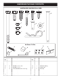
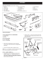
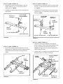
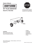
Owner's Manual
®
UTILITY 10 POLY
CONVERTIBLE CART
STOP
DO NOT RETURN TO STORE
For Missing Parts or Assembly
Questions Call 1-866-576-8388
Model No. 486.243201
CAUTION:
Before using this product, read
this manual and follow all Safety
Rules and Operating Instructions.
•
•
•
•
•
Safety
Assembly
Operation
Maintenance
Parts
Sears, Roebuck and Co., Hoffman Estates, IL 60179 U.S.A.
www.sears.com/craftsman
PRINTED IN USA
FORM NO. 40303 (6/06)
TABLE OF CONTENTS
Maintenance .............................................................9
Storage .....................................................................9
Repair Parts Illustration ..........................................10
Repair Parts List .....................................................10
Slope Gauge...........................................................11
Parts Ordering/Service ............................ Back Cover
Safety Rules .............................................................2
Warranty ...................................................................2
Full Size Hardware Chart .........................................3
Assembly ..................................................................4
Operation ..................................................................8
SAFETY
Any power equipment can cause injury if operated improperly or if the user does not understand how to operate the equipment.
Exercise caution at all times, when using power equipment.
•
•
•
•
•
•
•
•
Read this owners manual before attempting to
assemble or operate the cart.
Read the vehicle owners manual and know how to
operate your tractor before using the cart attachment.
Do not at any time carry passengers in this cart. It has
not been designed to carry passengers.
Never allow children to operate the tractor or the cart
attachment.
Do not allow adults to operate the tractor or cart
attachment without proper instructions.
Always begin with the transmission in first (low) and
gradually increase speed as conditions permit.
Tow the cart at reduced speed over rough terrain and
hillsides or near creeks and ditches to prevent tipping
over and loss of control. Do not drive too close to a
creek or ditch.
•
•
•
•
•
Vehicle braking and stability may be affected with the
attachment of this cart. Do not fill cart to maximum
weight capacity without checking the capability of the
towing vehicle to safely pull and stop with the cart
attached.
Before operating vehicle on any grade (hill) refer to
safety rules in the vehicle owner's manual concerning
safe operation on slopes. Refer also to the slope guide
on page 11 of this manual. Be aware of changing
conditions on slopes. Stay off steep slopes!
Do not tow this cart on highways or public
thoroughfares.
Maximum towing speed is 10 m.p.h.
Do not load more weight into the push cart than you
can handle and control comfortably.
Follow maintenance and lubrication instructions as
outlined in this manual.
Look for this symbol to point out important safety precautions. It means — Attention!!
Become alert!! Your safety is involved.
WARRANTY
ONE YEAR FULL WARRANTY
When operated and maintained according to the instructions supplied with it, if this Convertible Cart fails due to a defect in
material or workmanship within one year from the date of purchase, call 1-800-4-MY-HOME® to arrange for free repair (or
replacement if repair proves impossible).
If this product is used for commercial or rental purposes, this warranty applies for only 90 days from the date of purchase
This warranty gives you specific legal rights, and you may also have other rights which vary from state to state.
Sears, Roebuck and Co., D817WA, Hoffman Estates, IL 60179
The model number and serial numbers will be found on
a decal attached to the cart.
You should record both the serial number and the date of
purchase and keep in a safe place for future reference.
2
MODEL NUMBER:
486.243201
SERIAL NUMBER:
__________________
DATE OF PURCHASE:
__________________
HARDWARE PACKAGE CONTENTS
HARDWARE SHOWN FULL SIZE
A
C
B
F
E
D
J
G
I
H
K
M
L
Not Shown Full Size
N
R
O
Q
P
Ref.
No.
Quant.
A
B
C
D
E
F
G
H
I
J
1
2
2
6
3
8
1
1
6
9
S
Description
Hex Bolt, 3/8" x 4"
Hex Bolt, 3/8" x 1"
Hex Bolt, 5/16" x 1"
Hex Bolt, 1/4" x 1-3/4"
Hex Bolt, 1/4" x 1"
Truss Head Bolt, 5/16" x 3/4" Lg.
Clevis Pin, 3/8" x 4"
Clevis Pin, 3/8" x 1"
Flat Washer, 1/4"
Nylock Nut, 1/4"
3
Ref.
No.
Quant.
K
L
M
N
O
P
Q
R
S
10
3
3
1
1
2
1
6
2
Description
Nylock Nut, 5/16"
Nylock Nut, 3/8"
Hairpin Cotter, 1/8"
Extension Spring
Plastic Cap
Hub Cap
Hitch Pin
Noise Reduction Pad
Axle Clip
ASSEMBLY
CARTON CONTENTS (Loose Parts in Carton)
1.
2.
3.
4.
5.
Poly Tray
Handle Tube
Front Tongue
Rear Tongue
Latch Stand Plate
11. Wheel Support
12. Axle
13. Wheels (2)
14. Handle Grip
6. Latch Stand Bracket
7. Hitch Bracket
8. Leg Stand Bracket
9. Latch Lock
10. Latch Mount Brackets (2)
1
14
11
2
12
5
13
6
3
9
4
8
10
7
CARTON CONTENTS
TOOLS REQUIRED FOR ASSEMBLY
(1) Screwdriver
(1) Pliers
(2) 7/16" Wrenches
(2) 1/2" Wrenches
(2) 9/16" Wrenches
•
Remove the hardware pack and all loose parts
from the carton. Be sure the carton is empty before
discarding.
•
Lay out all the parts shown on pages 3 and 4.
•
Insert the 3/8" x 1" clevis pin (H) through the holes
in the latch mount brackets and secure with an 1/8"
hairpin cotter (M).
LATCH MOUNT
BRACKETS
(E) 1/4" x 1"
HEX BOLT
(J) 1/4" NYLOCK NUT
(N) EXTENSION
SPRING
NOTE: All 1/4" flat washers should be assembled so that
they rest directly against the poly tray surface.
STEP 1: (SEE FIGURE 1)
•
(M) 1/8" HAIRPIN
COTTER
Assemble the latch lock between the latch mount
brackets using a 1/4" x 1" hex bolt (E) and a 1/4"
nylock nut (J). Tighten so that the latch lock can still
pivot. Attach the extension spring (N) to the latch lock
and the latch mount bracket.
(H) 3/8" x 1"
CLEVIS PIN
4
FIGURE 1
LATCH LOCK
STEP 2: (SEE FIGURE 2)
•
Assemble the latch lock subassembly to the rear
tongue using two 1/4" x 1" hex bolts (E) and 1/4"
nylock nuts (J). Tighten.
STEP 4: (SEE FIGURE 4)
•
Assemble the hitch bracket to the front tongue using
two 3/8" x 1" hex bolts (B) and 3/8" hex nylock nuts
(L). Tighten.
•
Assemble the plastic cap (O) to the front end of the
rear tongue.
•
Assemble the leg stand bracket to the front tongue
using two 5/16" x 1" hex bolts (C) and 5/16" nylock
nuts (K). Tighten.
(E) 1/4" x 1"
HEX BOLT
LATCH LOCK
SUB-ASSEMBLY
LEG STAND
BRACKET
(B) 3/8" x 1"
HEX BOLT
(C) 5/16" x 1"
HEX BOLT
HITCH
BRACKET
REAR
TONGUE
(J) 1/4" NYLOCK NUT
FRONT
TONGUE
(O) PLASTIC CAP
(K) 5/16" NYLOCK NUT
FIGURE 2
(L) 3/8" NYLOCK NUT
FIGURE 4
STEP 5: (SEE FIGURE 5)
•
Place the front tongue inside the rear tongue as
shown in figure 5. Fasten the tongues together using
a 3/8" x 4" hex bolt (A) and a 3/8" nylock nut (L).
Tighten, leaving the nut just loose enough that the
tongues can pivot freely.
•
Insert the 3/8" x 4" clevis pin (G) through the tongues
and secure with a 1/8" hairpin cotter (M).
STEP 3: (SEE FIGURE 3)
•
Lay the rear tongue (open side facing up) onto the
Wheel Support. Assemble the axle through the wheel
support and the second hole from the end of the
tongue.
AXLE
(M) 1/8" HAIRPIN
COTTER
FRONT
TONGUE
REAR
TONGUE
(L) 3/8"
NYLOCK NUT
WHEEL
SUPPORT
(G) 3/8" x 4"
CLEVIS PIN
FIGURE 3
FIGURE 5
5
(A) 3/8" x 4"
HEX BOLT
STEP 6: (SEE FIGURE 6)
•
(F) 5/16" x 3/4"
TRUSS HEAD
BOLT
Assemble an axle clip (S) and a wheel with the valve
stem facing out onto the axle. Assemble a hub cap
(P) by pressing or tapping it onto the axle. Repeat on
other end of axle.
WHEEL
AXLE
(K) 5/16"
NYLOCK NUTS
(S) AXLE CLIP
(P) HUB CAP
LATCH
STAND
PLATE
FIGURE 6
PADS (R)
LATCH STAND
BRACKET
FIGURE 7
STEP 8: (SEE FIGURE 8)
STEP 7: (SEE FIGURE 7)
•
Attach two noise reduction pads (R) to the bottom of
the latch stand bracket.
•
Turn the assembled tongue, wheel support and
wheels over to the upright position. Place the latch
stand bracket onto the tongue between the latch lock
assembly and the raised tab. Place the poly tray onto
the wheel support and latch stand bracket. Fasten
the tray to the wheel support using eight 5/16" x 3/4"
truss head bolts (F) and 5/16" nylock nuts (K). Do not
tighten yet.
•
•
Insert two 1/4" x 1-3/4" hex bolts (D) through the
handle tube as shown in figure 8. Holding the bolts in
place in the handle, insert the bolts through the holes
in the poly tray, allowing the legs of the handle to slip
beneath the latch stand bracket. Secure the two bolts
with two 1/4" flat washers (I) and 1/4" nylock nuts (J).
Do not tighten yet.
(J) 1/4" NYLOCK
NUT
(I) 1/4" FLAT
WASHER
(D) 1/4" x 1-3/4"
HEX BOLT
Place the latch stand plate between the latch stand
bracket and the poly tray.
LATCH STAND
BRACKET
FIGURE 8
6
STEP 9: (SEE FIGURE 9)
•
•
STEP 10: (SEE FIGURE 11)
Align the holes in the handle with the holes in the
bottom of the poly tray, the latch stand plate and the
latch stand bracket. Fasten together using four 1/4"
x 1-3/4" hex bolts (D), 1/4" flat washers (I) and 1/4"
nylock nuts (J). Tighten.
•
Assemble the hitch pin (Q) through the tongue and
hitch bracket and secure it with the 1/8" hairpin cotter
(M).
(Q) HITCH PIN
At this time tighten all bolts which were left loose.
(I) 1/4" FLAT
WASHER
(D) 1/4" x 1-3/4"
HEX BOLT
HITCH
BRACKET
(M) 1/8" HAIRPIN
COTTER
FIGURE 11
(J) 1/4"
NYLOCK
NUT
FIGURE 9
STEP 11: (SEE FIGURE 12)
•
CART WITH TONGUE ARRANGED FOR TOWING
Attach two noise reduction pads (R) on each side of
the front tongue.
LATCH LOCK
FRONT
TONGUE
(H) 3/8" x 1"
CLEVIS PIN
PADS (R)
(G) 3/8" x 4"
CLEVIS PIN
FIGURE 10
PADS (R)
FIGURE 12
7
OPERATION
KNOW YOUR CART
HANDLE TUBE
LATCH LOCK
LEG STAND
BRACKET
HITCH PIN
LATCH LOCK
CLEVIS PIN
3/8" x 4"
CLEVIS PIN
HANDLE TUBE
LATCH LOCK
FRONT TONGUE
LEG STAND BRACKET
HITCH PIN
3/8" x 4" CLEVIS PIN
LATCH LOCK CLEVIS PIN
FRONT
TONGUE
Used to transport and dump the cart when it is converted into a push cart.
Secures the cart bed to the tongue.
Extends forward or folds under the cart for towing with a tractor or pushing by hand.
Supports the front of the cart when the front tongue is folded under the cart.
Use to attach the cart to your tractor.
Secures the front tongue in either the extended (shown) or folded position.
Prevents the latch lock mechanism from accidentally releasing.
HOW TO USE YOUR TOW CART
•
DO NOT EXCEED 500 LB. CAPACITY OF CART
One cubic foot of dirt weighs approximately 80 lbs.
•
CAUTION: Vehicle braking and stability
may be affected with the addition of an
accessory or attachment. Be aware of
changing conditions on slopes.
•
•
USING AS A TOW CART
• To convert the cart for towing, remove the plastic cap
from the tongue. Remove the 4" long clevis pin and
hairpin cotter which secure the front tongue in storage
position underneath the rear tongue. Pivot the front
tongue outward and secure it in the towing position
using the same clevis pin and hairpin cotter. Refer to
drawing above.
• The maximum towing speed for this cart is 10 m.p.h.
• Refer to the vehicle owners manual for instructions on
safe operation on slopes.
Use the slope guide provided on page 11 of this
manual to determine whether slope angle is too steep
for safe operation.
Always test to make sure your tractor has adequate
towing and braking capabilities whenever hauling a
substantial amount of weight in your cart. Use extra
caution when operating on slopes.
For best handling and traction, distribute the weight of
the load evenly in the cart.
To dump material from the cart, remove the 1" long
clevis pin from the latch on the tongue and release the
latch. The cart bed will then tilt backwards to empty
its contents. After emptying, pull the front of the bed
down toward the cart tongue until the latch snaps into
place. Reinstall the clevis pin in the latch to prevent
accidental release of the latch.
CAUTION: To avoid possible injury,
be sure no one is near the cart before
releasing the latch.
8
USING AS A PUSH CART
IMPORTANT: Leave the latch lock clevis pin in place at
all times while using the cart as a push cart. The clevis
pin is shown in figure 1 on page 4.
•
For best handling, and to help prevent accidental
tipping, distribute the weight of the load evenly in the
cart.
•
•
Do not load more weight into the push cart than you
can handle and control comfortably.
•
To dump material from the push cart, lift up on the
handle and tilt the cart forward. Be sure that the latch
mechanism on the tongue is locked and secured with
the clevis pin to prevent accidental release of the
latch.
To convert the cart for push operation, remove the 4"
long clevis pin and hairpin cotter which secure the
tongue in the towing position. (See drawing on page
8.) Pivot the front tongue into the storage position
underneath the rear tongue and secure it using the
same clevis pin and hairpin cotter. (See figure 5 on
page 5.) Place the plastic cap over the exposed end
of the tongue.
MAINTENANCE/STORAGE
CUSTOMER RESPONSIBILITIES
Read and follow the maintenance schedule and the procedures listed in the maintenance section.
e
us se r
n
ge
ch ch u yea aso tora
a
se e s
a
e e ea
for fter wice very efor
e
T
B
A
E
B
MAINTENANCE SCHEDULE
Fill in dates as you
complete regular service.
Check for loose fasteners
Check for worn or damaged parts
Check tire pressure
Lubricate
Clean
Service Dates
X
X
X
X
X
X
SCHEDULED MAINTENANCE
•
•
•
Check for loose fasteners before each use.
Check for worn or damaged parts before each use.
Keep tires filled to recommended tire pressure printed
on the tire.
OIL
CAUTION: DO NOT inflate tires beyond
the maximum recommended pressure
printed on side of tire.
GREASE
•
•
At the beginning of each season, using a light
machine oil, lubricate the latch, the latch pivot bolt,
and the area of the axle where the draw bar tongue
pivots. See figure 13.
Grease or oil the wheel bearings periodically (at least
once each season). Use grease or 20 weight oil. See
figure 13.
FIGURE 13
CART SPECIFICATIONS
STORAGE
•
•
•
OIL
Tires:
Axle:
Capacity:
Approx. Sh. Wt.
Clean thoroughly before storing.
Remove any rust from painted surfaces and coat with
touch up paint.
Store in a dry area.
9
14" x 4" Pneumatic
5/8" Dia. Steel
Up to 500 Lbs. Max.
55 Lbs.
PARTS
30
19
21
17
19
1
A
6
7
8
A
31
9
30
17
23
3
16
11
2
22
2
33
26
5
17
25
24
10
18
25
27
29
12
14
28
20
13
15
17
4
22
32
18
REF
NO
PART
NO
QTY
1
2
3
4
5
6
7
8
9
10
11
12
13
14
15
16
17
48791
24908
48497
24392
24391
24386
23297
48834
24527
62020
23470
23353
23014
24390
47029
45091
47189
1
1
2
1
1
1
1
1
1
1
2
1
1
1
1
1
9
DESCRIPTION
REF
NO
PART
NO
18 HA21362
19
43088
20
43001
21
43814
22
47810
23
43661
24
43000
25
43343
26
48499
27
47038
28
43063
29
43036
30 1509-69
31
48836
32
48661
33
25910
40303
Poly Tray
Axle
Wheel Assembly
Tongue, Front
Tongue, Rear
Latch Stand Plate
Latch Stand Bracket
Handle Tube
Wheel Support
Latch Lock
Bracket, Latch Mounting
Hitch Pin
Hitch Bracket
Leg Stand Bracket
Clevis Pin, 3/8" x 4"
Clevis Pin 3/8" x 1"
Nylock Nut 1/4-20 Thread *
10
QTY
3
6
2
8
10
3
1
3
2
1
2
1
6
1
6
2
1
25
DESCRIPTION
Nylock Nut, 3/8-16 Thread *
Washer, Flat 1/4" Std. Wrought
Hex Bolt, 3/8-16 x 1" Lg. *
Truss Hd Bolt, 5/16-18 x 3/4" Lg.*
Nylock Nut, 5/16-18 Thread *
Hex Bolt, 1/4-20 x 1" *
Extension Spring
Hairpin, Cotter 1/8"
Hub Cap
Plastic Cap
Hex Bolt, 5/16-18 x 1" Lg. *
Hex Bolt, 3/8-16 x 4" Lg. *
Hex Bolt, 1/4-20 x 1-3/4" Lg. *
Foam Grip
Noise Reduction Pad
Axle Clip, 5/8"
Owner's Manual
SUGGESTED GUIDE FOR SIGHTING SLOPES FOR SAFE OPERATION
OF TRACTOR WITH ATTACHMENT
FOLD
ALO
N
G
D
THIS IS
OTTED
LINE
A 10
D
E
G
REE S
LOPE
ONLY RIDE UP AND DOWN HILL,
NOT ACROSS HILL
10 DEGREES MAX.
WARNING: To avoid serious injury, operate your tractor up and
down the face of slopes, never across the face. Do not operate
on slopes greater than 10 degrees. Make turns gradually to
prevent tipping or loss of control. Exercise extreme caution
when changing direction on slopes. Braking may be affected by
tractor attachment. Reduce speed on slopes.
1. Fold this page along dotted line indicated above.
2. Hold page before you so that its left edge is vertically parallel to a tree
trunk or other upright structure.
3. Sight across the fold in the direction of hill slope you want to measure.
4. Compare the angle of the fold with the slope of the hill.
11
Get it fixed, at your home or ours!
Your Home
For repair – in your home – of all major brand appliances,
lawn and garden equipment, or heating and cooling systems,
no matter who made it, no matter who sold it!
For the replacement parts, accessories and
owner’s manuals that you need to do-it-yourself.
For Sears professional installation of home appliances
and items like garage door openers and water heaters.
1-800-4-MY-HOME®
(1-800-469-4663)
Call anytime, day or night (U.S.A. and Canada)
www.sears.com
www.sears.ca
Our Home
For repair of carry-in items like vacuums, lawn equipment,
and electronics, call or go on-line for the location of your nearest
Sears Parts & Repair Center.
1-800-488-1222
Call anytime, day or night (U.S.A. only)
www.sears.com
To purchase a protection agreement (U.S.A.)
or maintenance agreement (Canada) on a product serviced by Sears:
1-800-827-6655 (U.S.A.)
1-800-361-6665 (Canada)
Para pedir servicio de reparación
a domicilio, y para ordenar piezas:
Au Canada pour service en français:
1-800-LE-FOYER MC
1-888-SU-HOGAR®
(1-800-533-6937)
www.sears.ca
(1-888-784-6427)
® Registered Trademark / TM Trademark / SM Service Mark of Sears Brands, LLC
® Marca Registrada / TM Marca de Fábrica / SM Marca de Servicio de Sears Brands, LLC
MC Marque de commerce / MD Marque déposée de Sears Brands, LLC
12
© Sears Brands, LLC