1
perator's
I:RnFrSMRN°
LAWN TRACTOR
20 Horsepower
Hydrostatic
Transmission
42" Deck
Model No. 247.28905
• Espanol,
P. 59
This product has a low emission
engine which operates
differently
from previously built engines. Before you start the engine, read and
understand
this Operator's Manual.
For answers to your questions
this product, Call:
Before using this equipment,
read this manual and follow
1-800=659=5917
all safety rules and operating
instructions.
Sears Brands
Management
about
Craftsman Tractor Help Line
7 am = 7 pm CT, Mort. =Sun.
Corporation,
Visit our website:
Hoffman
www.craftsman.com
Estates,
IL 60179 U.S.A.
FormNo.769-05573A
(February
12,2010)
Off-Season Storage ........................................................
27
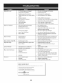
Trou bleshooting ..............................................................
28
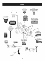
Labels .............................................................................
29
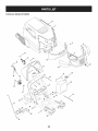
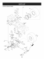
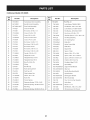
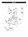
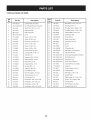
Parts List .........................................................................
30
Espafiol ............................................................................
59
Service Numbers .............................................
Back Cover
CRAFTSMAN
FULL WARRANTY
Whenoperatedand maintainedaccordingto all suppliedinstructions,
ifany non-expendablepartof this ridingequipmentfails due to a defectin
materialor workmanshipwithintwo yearsfrom thedate or purchase,call 1-800-659-5917to arrangefor free in-homerepair.
Theframe and frontaxle will be repairedfreeof chargefor five yearsfrom the dateof purchaseif defectivein materialor workmanship.
All of the abovewarrantycoverageappliesfor only90 days fromthe dateof purchaseifthis ridingequipmentiseverusedfor commercialor
rentalpurposes.
In all cases, if repairprovesimpossible,
the ridingequipmentwill be replacedfree of chargewith the sameor an equivalentmodel.
The batterywill be replacedfree of chargefor 90 daysfrom the dateof purchaseifdefectivein materialor workmanship(our testingprovesthat it
will nothold a charge).
Thiswarranty coversONLYdefects in material and workmanship. Sears will NOT payfor:
Expendableitemsthat becomewornduringnormaluse, includingbutnot limitedto blades,spark plugs,air cleaners,belts,
and oil filters.
o
Standardmaintenanceservicing,oil changes,or tune-ups.
o
Tire replacementor repaircausedby puncturesfrom outsideobjects,such as nails,thorns,stumps,or glass.
Tireor wheelreplacementor repairresultingfrom normalwear,accident,or improperoperationor maintenance.
o
o
Repairsnecessarybecauseof operatorabuse, includingbutnot limitedto damagecausedby towingobjectsbeyondthe
capabilityof the ridingequipment,impactingobjectsthat bend theframe or crankshaft,or over-speedingthe engine.
Repairsnecessarybecauseof operatornegligence,includingbut not limitedto, electricaland mechanicaldamagecaused
by improperstorage,failureto use the propergradeand amountof engineoil, failureto keepthe deckclear of flammable
debris,or failureto maintainthe ridingequipmentaccordingto the instructionscontainedinthe operator'smanual.
Engine(fuelsystem)cleaningor repairscausedbyfuel determinedto be contaminatedor oxidized(stale).In general,fuel
shouldbe usedwithin 30 days of itspurchasedate.
Normaldeteriorationand wearof the exteriorfinishes,or productlabel replacement.
Thiswarrantyappliesonly whilethis productiswithinthe UnitedStates.
This warrantygivesyou specificlegal rights,and you mayalso haveotherrightswhich vary from stateto state.
Sears Brands ManagementCorporation, HoffmanEstates, IL 60179
Gross HP:
20
EngineOil:
Fuel:
SAE 30
UnleadedGasoline
SparkPlug:
Champion®RC12YC
Engine:
Briggs& StrattonIntek®
© KCD IR LLC
Model Number:
Serial Number:
Dateof Purchase:
Recordthe modelnumber,serialnumber,
and dateof purchaseabove.
2
This machinewas builtto be operatedaccordingto the safeoperation practicesin this manual.As with anytype of powerequipment,
carelessnessor error on the partof the operatorcan resultin serious
injury.This machineis capableof amputatingfingers,hands,toes
and feet and throwingdebris.Failureto observethe followingsafety
instructionscouldresultin seriousinjuryor death.
This symbolpointsout importantsafetyinstructionswhich,if not
followed,couldendangerthepersonalsafetyand/orpropertyof
yourselfand others. Readand followall instructionsin this manual
beforeattemptingto operatethis machine.Failureto complywith
these instructionsmay resultin personalinjury.Whenyou seethis
symbol,HEEDITS WARNING!
CALIFORNIA
PROPOSITION
65
Your Responsibility--Restrict the useof this powermachineto
personswho read,understandand follow thewarningsand instructions in this manualand on the machine.
EngineExhaust,someof its constituents,and certainvehicle
componentscontainor emit chemicalsknownto Stateof California
to cause cancerand birthdefects or other reproductiveharm.
Batteryposts,terminals,and relatedaccessoriescontainlead and
leadcompounds,chemicalsknownto the Stateof Californiato
cause cancerand reproductiveharm.Washhandsafter handling.
GENERAL
•
•
•
OPERATION
Neverallowadultsto operatethis machinewithoutproper
instruction.
•
Tohelp avoidbladecontactor a thrownobjectinjury, keep
bystanders,helpers,childrenand pets at least 75 feet fromthe
machinewhile it is in operation.Stopmachineif anyoneenters
the area.
•
•
Read,understand,and followall instructionson the machineand
in themanual(s)beforeattemptingto assembleand operate.
Keepthis manualin a safe placefor futureand regularreference
and for orderingreplacementparts.
Be familiarwith all controlsand their properoperation.Knowhow
to stop the machineand disengagethemquickly.
Neverallowchildrenunder 14 yearsold to operatethis machine.
Children14 yearsold and over shouldreadand understandthe
operationinstructionsand safety rulesin this manualand should
be trainedand supervisedbya parent.
•
•
SAVE THESE INSTRUCTIONS!
•
•
Be awareof the mowerand attachmentdischargedirectionand
do not pointit at anyone.Donot operatethe mowerwithoutthe
dischargecover or entiregrass catcherin its properplace.
Donot put handsor feet near rotatingpartsor underthe cutting
deck. Contactwith the blade(s)can amputatehandsand feet.
A missingor damageddischargecovercan causeblade contact
or thrownobject injuries.
•
Stoptheblade(s)whencrossinggraveldrives,walks,or roads
and while notcuttinggrass.
Watchfor trafficwhenoperatingnear or crossingroadways.This
machineis not intendedfor useon any public roadway.
•
Thoroughlyinspectthe area wherethe equipmentis to be used.
Removeall stones,sticks,wire, bones,toys,and otherforeign
objectswhich couldbe pickedup and thrownby the blade(s).
Thrownobjectscan causeseriouspersonalinjury.
Planyour mowingpatternto avoiddischargeof materialtoward
roads,sidewalks,bystandersand the like.Also, avoiddischarging materialagainsta wall or obstructionwhich maycause
dischargedmaterialto ricochetback towardthe operator.
•
•
•
3
Alwayswear safetyglassesor safetygogglesduring operation
and while performingan adjustmentor repairto protectyoureyes.
Thrownobjectswhich ricochetcancause seriousinjuryto the
eyes.
Wearsturdy,rough-soledwork shoesand close-fittingslacksand
shirts.Loosefittingclothesand jewelry canbe caughtin movable
parts.Neveroperatethis machinein bare feet or sandals.
Donot operatethe machinewhile underthe influenceof alcohol
or drugs.
Mowonly in daylightor good artificiallight.
Nevercarry passengers.
Disengageblade(s)beforeshiftinginto reverse.Backup slowly.
Alwayslookdownand behindbeforeand while backingto avoida
back-overaccident.
•
SLOPE
Slowdownbeforeturning.Operatethe machinesmoothly.Avoid
erraticoperationand excessivespeed.
Disengageblade(s),set parkingbrake,stopengine and wait until
the blade(s)come to a completestop beforeremovinggrass
catcher,emptyinggrass,uncloggingchute,removinganygrass or
debris,or makinganyadjustments.
OPERATION
Slopesare a majorfactorrelatedto loss of controland tip-over
accidentswhichcan result in severeinjuryor death.All slopes require
extra caution.If youcannot back up the slopeor if youfeel uneasyon
it, do not mowit.
Foryoursafety,use the SlopeGuide includedas partof this manual
to measureslopesbeforeoperatingthis machineon a slopedor hilly
area. If the slopeis greaterthan15 degreesas shownon the Slope
Guide,do notoperatethis machineon that area or seriousinjurycould
result.
Neverleavea runningmachineunattended.Alwaysturnoff
blade(s),set parkingbrake,stopengine and removekey before
dismounting.
Use extracare whenloadingor unloadingthe machineintoa
traileror truck. This machineshouldnot be drivenup or down
ramp(s),becausethe machinecouldtip over,causingserious
personalinjury.The machinemustbe pushedmanuallyon
ramp(s)to loador unloadproperly.
Do:
o
Mowup and down slopes,not across.Exerciseextremecaution
whenchangingdirectionon slopes.
•
Watchfor holes,ruts,bumps,rocks,or other hiddenobjects.
Uneventerraincouldoverturnthe machine.Tallgrass can hide
obstacles.
Mufflerand engine becomehotand can causea burn.Do not
touch.
Checkoverheadclearancescarefullybeforedrivingunderlow
hangingtree branches,wires,door openingsetc., wherethe
operatormay be struckor pulledfrom the machine,which could
result in seriousinjury.
Disengageall attachmentclutchesand depressthe brakepedal
completelybeforeattemptingto start engine.
•
Yourmachineisdesignedto cut normalresidentialgrass of a
heightno morethan 10".Do not attemptto mowthroughunusually
tall, dry grass (e.g.,pasture)or piles of dry leaves.Dry grass or
•
leavesmaycontactthe engineexhaustand/or build up on the
mowerdeck presentinga potentialfire hazard.
Use onlyaccessoriesand attachmentsapprovedfor this machine
by the machinemanufacturer.Read,understandand followall
instructionsprovidedwith the approvedaccessoryor attachment.
Fora list of approvedaccessoriesand attachments,call 1-800•
659-5917.
Useslow speed.Choosea lowenoughspeedsettingso that
you will nothaveto stop or shiftwhileon the slope.Tires may
lose tractionon slopeseventhoughthe brakesare functioning
properly.Alwayskeepmachinein gearwhen goingdownslopes
to take advantageof enginebrakingaction.
Followthe manufacturer'srecommendationsfor wheelweights
or counterweightsto improvestability.Forrecommendations,call
1-800-659-5917.
Useextra carewith grass catchersor otherattachments.These
can changethe stabilityof the machine.
Keepall movementon the slopes slowand gradual.Do not make
suddenchangesin speedor direction.Rapidengagementor
brakingcouldcausethe front of the machineto lift and rapidlyflip
overbackwardswhich couldcauseseriousinjury.
Avoidstartingor stoppingon a slope. If tires losetraction,disengage the blade(s)and proceedslowlystraightdownthe slope.
Do Not:
Data indicatesthat operators,age 60 years and above,are
involvedin a largepercentageof riding mower-relatedinjuries.
Theseoperatorsshouldevaluatetheirability to operatethe riding
mowersafelyenoughto protectthemselvesand othersfrom
seriousinjury.
If situationsoccurwhich are not coveredin this manual,usecare
and goodjudgment.Contact1-800-659-5917for informationand
assistance.
•
•
•
•
4
Donot turnon slopesunlessnecessary;then, turnslowlyand
graduallydownhill,if possible.
Donot mow neardrop-offs,ditchesor embankments.The mower
could suddenlyturnover if a wheelis overthe edgeof a cliff,
ditch,or if an edge cavesin.
Donot try to stabilizethe machineby puttingyourfoot on the
ground.
Donot usea grass catcheron steepslopes.
•
•
Donot mowon wet grass.Reducedtractioncouldcausesliding.
Donot attemptto coastdownhill.Over-speedingmaycausethe
operatorto lose controlof the machineresultingin seriousinjury
or death.
•
Donot tow heavypull behindattachments(e.g. loadeddumpcart,
lawn roller,etc.)on slopesgreaterthan5 degrees.Whengoing
down hill,the extraweighttends to pushthe tractorand may
causeyou to loosecontrol (e.g.tractormay speedup, brakingand
steeringability are reduced,attachmentmayjack-knifeand cause
tractorto overturn).
CHILDREN
SERVICE
Tragicaccidentscanoccur ifthe operatoris notalert to the presence
of children.Childrenare often attractedto the machineand the mowing
activity.They do notunderstandthe dangers.Neverassumethat
childrenwill remainwhereyou last sawthem.
•
Keepchildrenout of the mowingareaand inwatchfulcare of a
responsibleadultotherthanthe operator.
•
Be alert and turnmachineoff ifa childentersthe area.
SafeHandlingof Gasoline
Toavoidpersonalinjuryor propertydamageuse extremecarein
handlinggasoline.Gasolineisextremelyflammableand the vaporsare
explosive.Seriouspersonalinjurycanoccur whengasolineis spilled
on yourselfor your clotheswhich can ignite.Washyourskin and
changeclothesimmediately.
•
•
•
Beforeand whilebacking,lookbehindand downfor small
children.
Nevercarry children,evenwith the blade(s)shut off.They may
fall off and be seriouslyinjuredor interferewith safe machine
operation.
Use extremecarewhenapproachingblind corners,doorways,
shrubs,trees or otherobjectsthat may block yourvisionof a child
whomay run intothe machine.
Whenpractical,removegas-poweredequipmentfrom the truck
or trailerand refueliton theground.If this isnot possible,then
refuelsuch equipmenton a trailerwith a portablecontainer,rather
than froma gasolinedispensernozzle.
Keepthe nozzleincontactwith the rim of the fueltank or
containeropeningat all timesuntilfuelingiscomplete.Donot use
a nozzlelock-opendevice.
Toavoidback-overaccidents,alwaysdisengagethe cutting
blade(s)beforeshiftingintoReverse.If equipped,the "Reverse
CautionMode"(bladesoperatewhilemachineridesin reverse)
shouldnotbe usedwhenchildrenor othersare around.
Keepchildrenaway from hotor runningengines.They cansuffer
burnsfroma hotmuffler.
•
•
Removekeywhenmachineisunattendedto preventunauthorized
operation.
Neverallowchildrenunder 14 yearsof age to operatethis machine.
Children14 and overshouldreadand understandthe instructions
and
•
safeoperationpracticesin this manualand on the machineand should •
be trainedand supervisedbyan adult.
TOWING
Towonlywith a machinethat hasa hitch designedfor towing.Do
not attachtowedequipmentexceptat the hitch point.
Followthe manufacturersrecommendationforweight limitsfor
towedequipmentand towingon slopes.For recommendations,
call 1-800-659-5917.
Neverallowchildrenor othersin or on towedequipment.
On slopes,theweightof thetowed equipmentmaycause lossof
tractionand loss of control.
Alwaysuseextra cautionwhentowingwith a machinecapableof
makingtight turns (e.g."zero-turn"ride-onmower). Makewide
turnsto avoidjack-knifing.
Travelslowlyand allowextradistanceto stop.
Do notcoastdownhill.
Useonly an approvedgasolinecontainer.
Neverfill containersinsidea vehicleor on a truckor trailer bed
with a plasticliner.Alwaysplacecontainerson the groundaway
from yourvehiclebeforefilling.
•
•
Extinguishall cigarettes,cigars,pipesand othersourcesof
ignition.
Neverfuel machineindoors.
Neverremovegascap or add fuelwhilethe engineis hotor running.Allowengineto coolat least two minutesbeforerefueling.
Neveroverfill fuel tank. Filltank to no morethan 1/2inchbelow
bottomof filler neckto allowspace forfuel expansion.
Replacegasolinecap and tightensecurely.
If gasolineis spilled,wipeitoff the engineand equipment.Move
machineto anotherarea.Wait 5 minutesbeforestartingthe
engine.
To reducefire hazards,keepmachinefree of grass,leaves,or
otherdebrisbuild-up.Cleanup oil or fuel spillageand removeany
fuel soakeddebris.
Neverstorethe machineor fuelcontainerinsidewherethere isan
open flame,sparkor pilotlight as on a waterheater,spaceheater,
furnace,clothesdryeror othergasappliances.
Allowa machineto coolat least five minutesbeforestoring.
General
Service
•
Donot changethe enginegovernorsettingsor over-speedthe
engine.The governorcontrolsthe maximumsafe operatingspeed
• Never
runanengine
indoors
orina poorly
ventilated
area.Engine
of the engine.
exhaust
contains
carbon
monoxide,
anodorless,
anddeadly
gas.
Maintainor replacesafetyand instructionlabels,as necessary.
• Before
cleaning,
repairing,
orinspecting,
make
certain
the
blade(s)
andallmoving
partshave
stopped.
Disconnect
thespark • Observeproperdisposallaws and regulationsfor gas, oil, etc.to
plugwireandground
against
theengine
toprevent
unintended
protecttheenvironment.
starting.
•
Accordingto the ConsumerProductsSafetyCommission(CPSC)
• Periodically
check
tomake
suretheblades
come
tocomplete
and the U.S.EnvironmentalProtectionAgency(EPA),this product
stopwithin
approximately
(5)fiveseconds
after
operating
the
has an AverageUsefulLifeof seven(7) years,or 270 hours
blade
disengagement
control.
Iftheblades
donotstopwithin
the
of operation.At the end of the AverageUsefulLife,buy a new
thistimeframe,
yourmachine
should
beserviced
professionally machineor havethe machineinspectedannuallybya Searsor
byaSears
orother
qualified
service
dealer.
otherqualifiedservicedealerto ensurethat all mechanicaland
safety systemsare workingproperlyand not wornexcessively.
• Check
brake
operation
frequently
asitissubjected
towear
during
Failureto do so can resultin accidents,injuriesor death.
normal
operation.
Adjust
andservice
asrequired.
DO NOT MODIFY ENGINE
• Check
theblade(s)
andengine
mounting
bolts
atfrequent
intervals
forproper
tightness.
Also,visually
inspect
blade(s)
Toavoid seriousinjuryor death,do notmodifyengine in anyway.
fordamage
(e.g.,
excessive
wear,
bent,
cracked).
Replace
the
Tamperingwith the governorsettingcanlead to a runawayengineand
blade(s)
withtheoriginal
equipment
manufacturer's
(O.E.M.) cause it to operateat unsafespeeds.Nevertamper with factorysetting
blade(s)
only,
listed
inthismanual.
Useofpartswhich
donot
of enginegovernor.
meet
theoriginal
equipment
specifications
mayleadtoimproper NOTICE REGARDING EMISSIONS
performance
andcompromise
safety!
are certifiedto complywith Californiaand federal
• Mower
blades
aresharp.
Wrap
theblade
orwear
gloves,
anduse Engineswhich
EPAemissionregulationsfor SORE(SmallOff RoadEquipment)are
extra
caution
whenservicing
them.
certifiedto operateon regularunleadedgasoline,and may include
• Keep
allnuts,
bolts,
andscrews
tighttobesuretheequipment
is
the followingemissioncontrol systems:EngineModification(EM)and
•
•
•
•
in safeworkingcondition.
Nevertamperwith the safetyinterlocksystemor othersafety
devices.Checktheir properoperationregularly.
ThreeWay Catalyst(TWO)if so equipped.
SPARK
After strikinga foreignobject,stop the engine,disconnectthe
spark plugwire(s) and groundagainstthe engine.Thoroughly
inspectthe machinefor anydamage.Repairthe damagebefore
startingandoperating.
Neverattemptto makeadjustmentsor repairsto the machine
whilethe engineis running.
ARRESTOR
This machineis equippedwith an internalcombustionengineand
shouldnotbe usedon or near anyunimprovedforest-covered,
brushcoveredor grass-coveredland unlessthe engine'sexhaust
systemisequippedwith a sparkarrestermeetingapplicablelocalor
statelaws (if any).
Grasscatchercomponentsand the dischargecoverare subject
to wearand damagewhich couldexposemovingparts or allow
objectsto be thrown.Forsafetyprotection,frequentlycheck
componentsand replaceimmediatelywith originalequipment
manufacturer's(O.E.M.)parts only,listed in this manual.Use of
parts whichdo not meetthe originalequipmentspecificationsmay
lead to improperperformanceandcompromisesafety!
If a sparkarresteris used,it shouldbe maintainedin effectiveworking
order by the operator.Inthe Stateof Californiatheaboveis required
by law (Section4442of the CaliforniaPublicResourcesCode). Other
states mayhavesimilarlaws.Federallaws applyon federallands.
A sparkarresterfor the mufflerisavailablethroughyournearestSears
Partsand RepairServiceCenter.
6
SAFETY
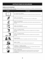
SYMBOLS
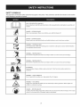
This pagedepictsand describessafety symbolsthat may appearon this product. Read,understand,and follow all instructions
on the machine
beforeattemptingto assembleand operate.
READ THE OPERATOR'S MANUAL(S)
Read, understand,
and follow
all instructions
in the manual(s) before
attempting
to assemble
and
operate
DANGER--
ROTATING BLADES
Never carry passengers.
Never carry children,
even with the blades off.
0
DANGER--
ROTATING BLADES
Always look down
WARNING--
and behind before
and while
backing
to avoid a back-over
accident.
ROTATING BLADES
Do not put hands or feet near rotating
can amputate
parts or under the cutting
deck. Contact with the blade(s)
hands and feet.
WARNING--THROWN
This machine
OBJECTS
may pick up and throw and objects
WARNING--THROWN
This machine
which can cause serious personal
injury.
which can cause serious personal
injury.
OBJECTS
may pick up and throw and objects
BYSTANDERS
Keep bystanders,
helpers,
children
and pets at least 75 feet from the machine
while
it is in
operation.
WARNING--
SLOPE OPERATION
Do not operate
A
WARNING--
this machine
HOT SURFACE
Engine parts, especially
muffler
on a slope greater than 15 degrees.
the muffler,
become extremely
hot during
operation.
Allow engine and
to cool before touching.
DANGER--
ROTATING BLADES
To reduce the risk of injury, keep hands and feet away. Do not operate
catcher is in its proper
place. If damaged,
7
replace immediately.
unless discharge
cover or grass
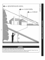
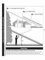
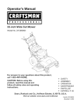
Sight and hold this levelwith a vertical tree...
|
I
|
|
I
|
i
or a corner of a building...
|
|
0o
15 °
Use this page as a guide to determine slopes where you may not operate safely.
Donot operateyourlawnmoweron such slopes.Do notmow on inclineswith a slope in excessof 15degrees(a rise of approximately2-1/2feet every 10feet). A riding
mowercouldoverturnand causeseriousinjury.Operateriding mowersup and downslopes,neveracrossthe face of slopes.
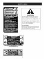
ROTATING BLADES CAUSE
SERIOUS INJURY OR DEATH
DONOTMOWWHENCHILDREN
OROTHERS
ARE
AROUND
NEVER
CARRY
CHILDREN
EVEN
WITHBLADE(S)
OFF.
LOOK
DOWNANDBEHIND
BEFORE
ANDWHILE
BACKING.
MOWING
INREVERSE
ISNOTRECOMMENDED.
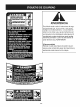
WARNING
This symbol points out important safety instructions
which, if not followed, could endangerthe personal
safety and/or property of yourself and others. Read and
follow all instructions in this manual before attempting
to operate this machine. Failure to comply with these
instructions may result in personal injury.When you see
this symbol HEED ITS WARNING!
Your Responsibility
Restrict the use of this power machine to persons who
read, understand, and follow the warnings and instructions in this manual and on the machine.
9
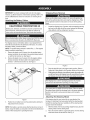
IMPORTANT:Yourtractoris shippedwith motoroil in theengine.
However,you MUSTcheckthe oil levelbeforeoperating.Referto the
Service& Maintenancesectionfor instructionson checkingtheoil
level.
Attaching
the Battery
CALIFORNIA
Shipping
Removal
Makesurethe ridingmower'sengineis off, removetheignitionkey,
and set the parkingbrakebeforeremovingthe shippingbrace. Refer
Ito the Operationsectionfor instructionson howto set the parking
lbrake.
Cables
PROPOSITION
Brace
65
•
Batteryposts,terminals,and relatedaccessoriescontainlead and
leadcompounds,chemicalsknownto the Stateof Californiato
cause cancerand reproductiveharm.Wash handsafter handling.
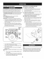
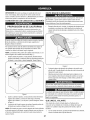
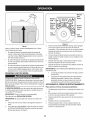
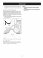
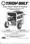
Locatethe shippingbrace, if present,and accompanyingwarning
tag foundon the rightsideof the mower,betweenthe discharge
chute deflectorand the cuttingdeck. See Fig. 2.
Whenattachingbatterycables,alwaysconnectthe POSITIVE(Red)
wireto its terminalfirst, followedby the NEGATIVE(Black)wire.
Forshippingreasons,bothbatterycables on yourequipmenthave
been left disconnectedfrom the terminalsat the factory.Toconnect
the batterycables,proceedas follows:
NOTE:Thepositivebatteryterminalis markedPos. (+).The negative
batteryterminalis markedNeg. (i).
1. Removethe plasticcover,if present,fromthe positivebattery
terminaland attachthe redcableto the positivebatteryterminal
(+)with the bolt and hexnut. See Figure1.
2.
Removethe plasticcover,if present,fromthe negativebattery
terminaland attachthe black cableto the negativebattery
terminal(-) with the bolt and hex nut. See Figure1.
f
Figure2
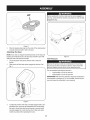
Placethe deck lift leverin the highestcuttingposition.Referto
Setting theCuttingHeightin the Operationsectionof this manual.
Whilepushingthedischargechuteddlectortowardsthemachinewith
yourlefthand,removetheshippingbracewithyourrighthandbygrasping itbetweenyourthumbandindexfingerandrotatingitclockwise.
The shippingbrace,usedfor packagingpurposesonly, mustbe
removedand discardedbeforeoperatingyour ridingmower.
The mowingdeck iscapableof throwingobjects. Failureto operate
the ridingmowerwithoutthe dischargecoverin the properoperating
Ipositioncould resultin seriouspersonalinjuryand/orproperty
ldamage.
Attaching
The Steering
Wheel
J
Figure1
3.
Positionthe red rubberbootoverthe positivebatteryterminalto
help protectit fromcorrosion.
NOTE:If thebatteryis put into serviceafter the dateshownon topof
battery,chargethe batteryas instructedin the Service & Maintenance
sectionof this manualprior to operatingthe tractor.
10
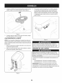
If the steeringwheelfor yourtractordid notcome attached,the
hardwarefor attachingit has beenpackedwithinthe steeringwheel,
beneaththe steeringwheelcap. Carefullypry off the steeringwheel
cap and removethe hardware.
1. With the wheelsof the tractorpointingstraightforward,placethe
steeringwheeloverthe steeringshaft.
2.
Placethe washer (with the cuppedside down) overthe steering
wheel and securewith the hexbolt. See Fig. 3.
f
Beforeoperatingthis machine,make surethe seat is engagedin a
seat stop,stand behindthe machineand pull back on seatuntil fully
_engagedntostop.
\
\
3.
Figure3
Placethe steeringwheelcap overthecenter of the steeringwheel
and pushdownwarduntilit "clicks"intoplace.
Attaching
The Seat
NOTE: If your seatwas shippedmountedbackwardson the seat pivot
bracket,pullout the tab foundon the seat stopand hold it open while
slidingtheseat off the seatpivot bracket.
1.
Line up the plasticseat spacerswith the slotsin seat pivot
bracket.
2.
Slide seat in untilfront seat spacerengagesthe seat stop.See
Fig. 4.
Figure5
Tire Pressure
Maximumtire pressureunderany circumstancesis 30 psi. Equal
tire pressureshouldbe maintainedat all times. Neverexceedthe
_maxmum nfat on pressureshownon the s dewa of thet re.
The recommendedoperatingtire pressureis:
•
Approximately10psi forthe reartires
•
Approximately14psi forthe front tires
IMPORTANT: Referto the tire sidewallfor exacttire manufacturer's
recommendedor maximumpsi. Donot overinfiate.Uneventirepressurecouldcausethe cuttingdeckto mowunevenly.
Figure4
.
Toadjustthe positionof the seat on modelsequippedwith a seat
adjustmentlever,movethe seat adjustmentlever(locatedunder
the seat)to the left and slidethe seatforwardor rearwarduntil it
securelyengagesintoa seat stop.See Fig. 5. Makesure seat is
lockedinto positionbeforeoperatingthetractor.
11
B
f----It
c
A
D
J
E
H
G
F
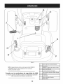
Figure6
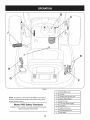
NOTE: Any referencein this manualto the RIGHTor LEFT sideof
the tractoris observedfromoperator'sseat positionfacingforward
towardsthe front of tractor.
Meets ANSI Safety Standards
CraftsmanTractorsconformto the safetystandardof theAmerican
NationalStandardsInstitute(ANSI).
12
A
B
ParkingBrakeLever
Ammeter
C
Throttle/ChokeControlLever
D
IgnitionSwitchModule
E
DeckLift Lever
F
PTOLever(Blade Engage)
G
Cup Holder
H
Speed ControlLever
I
J
SeatAdjustmentLever
BrakePedal
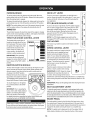
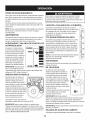
PARKING
BRAKE
DECK LIFT LEVER
Toset the parkingbrake,fully depressthe brakepedal.Movethe
parkingbrakeleverintothe ON position.Releasethebrakepedal to
allowthe parkingbraketo engage.
Foundon your tractor'srightfender,the deck lift leveris
usedto changethe heightof the cuttingdeck. Touse, move
the leverto the left, thenplacein the notchbest suitedfor
yourapplication.
Toreleasethe parkingbrake,depressthe brakepedaland movethe
parkingbrakeleverout of the ONpositionand into the OFFposition.
PTO (BLADE
Theammetermeasuresthe electricaloutput of the engine'scharging
system.Undernormaloperatingconditions,with engineat full throttle,
the ammetershouldindicatepositivecharge.
Thethrottle/chokecontrolleveris
locatedon the right sideof the tractor'sdash panel.This levercontrols
the speedof the engineand, when
pushedall theway forward,the
chokecontrolalso. Whenset in
a givenposition,thethrottlewill
maintaina uniformenginespeed.
iMPORTANT: Whenoperating
the tractorwith the cuttingdeck
engaged,be certainthat the throttle
leveris alwaysin the FAST(rabbit)
position.
IGNITION
SWITCH
LEVER
Foundon the tractor'srightfender,the PT0 (bladeengage)
leveris usedto engagepowerto the cuttingdeck or other
(separatelyavailable)attachments.Tooperate,movethe
leverall theway forward.Movingthe leverall the way
rearwardinto the PTOOFFpositiondisengagespowerto
the cuttingdeck/attachment.
AMMETER
CONTROL
Z
m
NOTE: The parkingbrakemustbe set if the operatorleavesthe seat
with the enginerunningor the enginewill automaticallyshut off.
THROTTLE/CHOKE
ENGAGE)
,11
NOTE: The PTO(bladeengage)levermustbe in the
disengaged(PTOOFF)positionwhenstartingthe engine.
LEVER
o
W
p_
m
"Zl.
m
-
CUP HOLDER
CHOKE
The tractor'scup holderis locatedon the fenderto the left
of the seat.
FAST
SPEED CONTROL
LEVER
The speedcontrollever,locatedon the left
fender,allowsyouto regulatethe travel
directionand groundspeedof the lawn
tractor.Touse, releasethe parkingbrake
and movethe speedcontrolleverforward
(totravelforward)or rearward(to travelin
reverse).The furtherforwardor rearward
that the leveris moved,the fasterthe
tractorwill travel.
SLOW
MODULE
IF
Placethe speedcontrolleverin the Cutting
Speed,or slower,positionwhenmowing.
Thekey switch moduleis usedto start and stop theengine.It is also
usedto activatethe ReverseCautionMode(bladesoperatewhile
riding in reverse).Insertkey intothe keyswitchmoduleand turn
clockwiseto the STARTposition.
Releasethe key intothe normalmowo,,....... oo,o
ing positiononceengine hasstarted.
@
Theheadlightswill be activatedin the
Normal(and ReverseCaution)modes.
iMPORTANT: Do NOTattemptto change
the directionof travelwhenthe tractoris
in motion.Seriousdamageto the tractor's
transmissioncould result.Alwaysbring thetractorto a completestop
beforemovingthespeedcontrol leverfrom forwardto reverseor vice
versa.
Tostop the engine,turnthe ignition
key counterclockwiseto the STOP
position.
iMPORTANT: Alwaysset the parkingbrakewhenleavingthe tractor
unattended.
IMPORTANT:Prior to operatingthe
tractor,referto both"SafetyInterlock
System"and "StartingThe Engine"
laterin this sectionof this manual
for detailedinstructionsregardingthe IgnitionSwitchModuleand
operatingthetractorin REVERSECAUTIONMODE.
Toadjusttheseatforwardor backwardon unitsequippedwitha quickadjustseat,slidethe seatadjustmentleverto theleftand repositionthe
seatto thedesiredposition.Oncea comfortablepositionisfound,release
the seatadjustmentleverto locktheseatin place.Referto theAssembly
of thismanualformoredetailedinstructions
on theseatadjustments.
SEAT ADJUSTMENT
BRAKE
LEVER
PEDAL
The brakepedalis locatedon the left side of the lawntractor,along
the runningboard.Depressthe brakepedalpartof theway downto
slowthe tractor'sgroundspeed. Depressthe pedal all the way downto
engagethe disc brakeand bring thetractorto a completestop.
Neverleavea runningmachineunattended.AlwaysdisengagePTO,
moveshift leverintoneutralposition,set parkingbrake,stop engine
and removekeyto preventunintendedstarting.
NOTE: The pedalmustbe depressedto startthe engine.Referto
SafetyInterlockSwitchesin theOperationSectionof this manual.
13
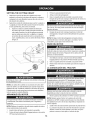
GAS AND OIL FILL-UP
0il
IMPORTANT: Yourtractorisshippedwith motoroil inthe engine.
However,you MUSTcheckthe oil levelbeforeoperating.Be careful
notto overfill.
Forinstructionson howto checkthe engineoil, referto CheckingThe
EngineOil in the Serviceand Maintenancesectionof this manual.
Gasoline
Thegasolinetank is locatedunderthe hood.Do notoverfill.
Use extremecarewhenhandlinggasoline.Gasolineis extremely
flammableand the vaporsare explosive.Neverfuel machineindoors
or whilethe engine is hotor running.Extinguishcigarettes,cigars,
_ppes, and othersourcesof gn t on.
NOTE : Purchasegasolinein small quantities.Do notuse gasolineleft
overfromthe previousseason,to minimizegumdepositsin the fuel
system.
•
•
•
•
•
•
•
1.
2.
3.
Figure7
This engineis certifiedto operateon unleadedgasoline.For best
results,fill the fueltank with onlyclean, fresh,unleadedgasoline
with a pumpstickeroctaneratingof 87 or higher.
Gasohol(up to 10%ethyl alcohol,90% unleadedgasolineby
volume)is an approvedfuel. Othergasoline/alcoholblends,such
as E85,are not approved.
MethylTertiaryButyl Ether(MTBE)and unleadedgasolineblends
(up to a maximumof 15%MTBEby volume)are approvedfuels.
Othergasoline/etherblendsare notapproved.
Fillfuel tank outdoorsor in well-ventilatedarea.
*
,
,
,
Do notoverfillfuel tank. Filltank to no morethan 1/2inch below
bottomof filler neck to allowspacefor fuel expansion.
Neverremovegas capor add fuel whilethe engineis hot or running.Allowengineto cool at leasttwo minutesbeforerefueling.
If gasolineis spilled,wipe it off theengineand equipment.Move
machineto anotherarea.Wait5 minutesbeforestartingthe
engine.
For California
,
Donot operatethe unitwhereit could slipor tip.
If machinestopsgoing uphill,stop bladesand backdownhill
slowly.
Donot mowwhenchildrenor othersare around.
,
,
Nevercarry children,evenwith bladesoff.
Lookdownand behindbeforeand whilebacking.
,
Keepsafetydevices(guards,shields,and switches)in place
and working.
Removeobjectsthat couldbe thrownby the blades.
Knowlocationand functionof all controls.
,
,
Turnthe engineoff and let enginecool at least2 minutesbefore
removingthe fuelcap. The gasolinetank is underthe hood,with
thefuel fill cap locatedon the left hand sideof the tank.
Fillthe fuel tank with gasoline.
Reinstallthe fuelcap.
Avoid Serious Injury or Death
Go up and downslopes,notacross.
Avoidsuddenturns.
,
Be surebladesand engine are stoppedbeforeplacinghandsor
feet near blades.
,
Beforeleavingoperator'sposition,stop tractor,disengage
blades,engageparkingbrake,shutengineoff, and removekey.
Read Operator's
SAFETY
Models:
ForCaliforniamodelsequippedwith a tethered,ratchetingfuelcap,
STOPfillingtank once fuelis seeninsidethe filler neck. This ensures
that a properexpansionvolumeis created,otherwisethefuel canoverflow creatinga hazardoussituation. Do NOTfill to the top of the filler
neck.On Californiamodels,fill thetank in accordancewith Figure7.
SYSTEM
The safetyinterlocksystemis designedfor safeoperationof the tractor. If this systemshouldevermalfunction,do not operatethe tractor,
immediatelycontact1-800-4-MY-HOME
to havethe systemserviced.
•
•
•
14
INTERLOCK
Manual
The safetyinterlocksystempreventsthe enginefrom starting
unless the parkingbrakeis engagedand the PTO(Blade Engage)
leveris in the disengaged(OFF) position.
The safetyinterlocksystemwill automaticallyshut off the engineif
the operatorleavesthe seat beforeengagingthe parkingbrake.
The safetyinterlocksystemwill automaticallyshut off the engine
if theoperatorleavesthe tractor'sseatwith the PTO(Blade
Engage)leverengaged,regardlessof whetherthe parkingbrake
is engaged.
REVERSE CAUTION MODE
ENGAGING
To engage
Use extremecautionwhileoperatingthetractorin the REVERSE
CAUTIONMODE.Alwayslookdownand behindbeforeand while
backing.Do notoperatethe tractorwhenchildrenor othersare
around.Stopthe tractorimmediately
if someoneentersthe area.
3.
Releasethe brakepedalto allowthe parkingbraketo engage.
3.
the parking
brake:
Depressthe brakepedaland movethe parkingbrakeleveroutof
the parkingbrake(ON)positionand intothe OFF position.
SETTING
THE
CUTTING
HEIGHT
Selectthe heightpositionof the cuttingdeck by placingthe deck
lift leverin anyof the six differentcutting heightnotcheson the
rightsideof the fender.
iMPORTANT: The operatorMUSTbe seatedinthe tractorseat.
1.
2.
brake:
Fullydepressthe brakepedal and hold it downwith yourfoot.
Movethe parkingbrakeleverall the waydownand intothe
parkingbrake(ON)position.
1.
iMPORTANT: Mowingin reverseisnot recommended.
Touse the REVERSECAUTIONMODE:
the parking
BRAKE
1.
2.
To release
The REVERSECAUTIONMODEpositionof the key switchmodule
allowsthe tractorto be operatedin reversewith the blades(PTO)
engaged.
THE PARKING
Startengineas instructed
underthe heading StartingTheEngine.
Turnthe key from the NORMALMO%NG (Green)positionto the
REVERSECAUTIONMODE(Yellow)positionof the keyswitch
module.See Figure8.
Depressthe REVERSEPUSHBUTTON(Orange,Triangular
Button)at the top, rightcornerof the key switchmodule.The red
indicator
light at the top, left cornerof the key switchmodulewill
be ON whileactivated.See Figure8.
Adjust thedeck wheelsso that they are between1A-inch
and
Y2-inchabovethe groundwhenthe tractoris on a smooth,flat
surfacesuch as a driveway.
a. Adjust thedeck wheelsby removingthe flangelock nut and
shoulderboltthat secureseachwheeland movingit intoone
of the holesthat allowsthe wheelsto be between_A-inchand
Y2-inchabovethe groundwhenthe tractoris on a smooth,
flat surfacesuch as a driveway.See Fig. 9
f
f
Reverse
Push
Button
Reverse
Caution
- Normal
Mode
Position
Driving
Mode
Stop
position
position
J
Figure 8
4.
5.
6.
Figure 9
Onceactivated(indicatorlightON), the tractorcan be drivenin
reversewith the cuttingblades(PTO)engaged.
Alwayslookdownand behindbeforeand whilebackingto make
sureno childrenare around.
Keephandsand feet away fromthe dischargeopeningof the cutting
deck.
After resumingforwardmotion,returnthe keyto the NORMAL
MO%NG position.
iMPORTANT: The REVERSECAUTIONMODEwill remainactivated
until:
a.
Thekey isplacedin eitherthe NORMALMO%NG position
or STOPposition.
Theoperatorengagesthe parkingbrakeby fully depressing
the brakepedaland holdingitdownwhile movingthe speed
controlleverintothe PARKBRAKEposition.
15
NOTE: Thedeck wheelsare an anti-scalpfeatureof the deck and
are notdesignedto supportthe weightof the cuttingdeck. Referto
Levelingin the Serviceand Maintenancesectionof this manualfor
moredetailedinstructions
regardingvariousdeck adjustments.
STARTING
THE ENGINE
1.
NOTE: Alwaysoperatethe tractorwith thethrottle/chokecontrol lever
in the FAST(rabbit)positionfor the mostefficientuseof the cutting
deck or other(separatelyavailable)attachments.
Do notoperatethe tractorifthe interlock
systemis malfunctioning.
This systemwasdesignedfor your safetyand protection.
NOTE: Referto the Gasolineand Oil fill-upinstructionsearlier in this
section.
1.
2.
Insertthe tractorkey intothe ignitionswitch.
Placethe PTO(BladeEngage)leverin the disengaged(OFF)
position.
3.
4.
Engagethe tractor'sparkingbrake.
Activatethe chokecontrol by movingthe throttle/chokeleverall
theway up intothe chokeposition.
Turnthe ignitionkey clockwiseto the STARTposition.After the
enginestarts,releasethe key.It will returnto the ON (or Normal
Mowing)position.
5.
2.
Releasethe parkingbrakeby depressingthe brakepedal
3.
Positionthe speedcontrolleverin desiredposition.Thefurther
forwardor rearwardthat the leverismoved,thefasterthe tractor
will travel.
DoNOTattemptto changethe directionof travel whenthe tractor
is in motion.Alwaysbringthe tractorto a completestop before
movingthe speedcontrol leverfromforwardto reverseor vice versa.
Failureto do so couldresult in seriousdamageto yourtractor's
transmission.
iMPORTANT: First-timeoperatorsshoulduseslowerspeeds.
Becomecompletelyfamiliarwith thetractor'soperationand controls
beforeoperatingthetractorin at higherspeed.
DO NOT holdthe key in the STARTpositionfor longerthanten
secondsat a time.Doingso maycause damageto yourengine's
electricstarter.
6.
4.
The lawntractorisbroughtto a stop by depressingthe brake
pedal.
5.
Set the parkingbrakeby fully depressingthe brakepedal and
keepingitdepressedwhileplacingthe parkingbrakeleverinthe
ON position.Releasethe brakepedal to allowthe parkingbrake
to engage.
Afterthe engine starts,deactivatethe chokecontroland placethe
throttlecontrolin the FASTposition.
NOTE: Do NOTleavethechokecontrol on whileoperatingthe tractor.
Doingso will resultin a "rich" fuel mixtureand causethe engineto run
poorly.
STOPPING
2.
3.
iMPORTANT: Whenstoppingthe tractorforany reasonwhile on a
grass surface,always:
1.
2.
Placethe speedcontrolleverin N (neutral),
Engagethe parkingbrake,
3. Shutengine off and removethe key.
Doingso will minimizethe possibilityof havingyour lawn"browned"by
hot exhaustfrom yourtractor'srunningengine.
If the bladesare engaged,placethe PTO(Blade Engage)leverin
thedisengaged(OFF) position.
Turnthe ignitionkey counterclockwiseto the STOPposition.
DRIVING
Removethe keyfrom the ignitionswitchto preventunintended
starting.
DRIVING
Beforeleavingthe operator'spositionfor any reason,disengagethe
blades,placethe speedcontrolleverin neutral,engagethe parking
brake,shut engineoff and removethe key.
THE ENGINE
If youstrikea foreignobject,stop the engine,disconnectthe spark
plug wire(s)and groundagainstthe engine.Thoroughlyinspectthe
machinefor anydamage.Repairthe damagebeforerestartingand
operating
1.
Movethethrottleleverintothe FAST(rabbit)position.
ON SLOPES
Referto the SLOPEGAUGEin the ImportantSafeOperationPractices
sectionof the manualto help determineslopeswhereyou mayoperate
the tractorsafely.
THE TRACTOR
Avoidsuddenstarts,excessivespeedand suddenstops.
Donot mowon inclineswith a slopein excessof 15degrees(a rise
of approximately2-1/2feetevery 10 feet).The tractorcouldoverturn
and cause seriousinjury.
Do notleavethe seat of thetractorwithoutfirstplacingthe PTO
(Blade Engage)leverin the disengaged(OFF) position,depressing
I the brakepedal and engagingthe parkingbrake.If leavingthe tractor
unattended,alsoturn the ignitionkey off and removethe key.
•
Mowup and down slopes,NEVERacross.
•
•
Alwayslookdownand behindbeforeand whilebackingup to avoida
back-overaccident.
Exerciseextremecautionwhenchangingdirectionon slopes.
Watchfor holes,ruts,bumps,rocks,or other hiddenobjects.
Uneventerraincouldoverturnthe machine.Tallgrass can hide
obstacles.
•
Avoidturns whendrivingon a slope.If a turnmustbe made,turn
downthe slope.Turningup a slopegreatly increases
the chance
of a rollover.
16
•
Avoidstoppingwhendrivingup a slope. If it is necessaryto stop
whiledrivingup a slope,start up smoothlyand carefullyto reduce
the possibilityof flippingthe tractoroverbackward.
ENGAGING
THE BLADES
Engagingthe PTO(Blade Engage)transferspowerto the cuttingdeck
or other (separatelyavailable)attachments.Toengagethe blades,
proceedas follows:
MOVING
Movethe throttle/chokecontrol leverto the FAST(rabbit)position.
Graspthe PTO(BladeEngage)leverand pivot it all the way
forwardintothe engaged(ON)position.
3.
Keepthe throttleleverin the FAST(rabbit)positionforthe most
efficientuseof thecuttingdeck or other(separatelyavailable)
attachments.
MANUALLY
Yourtractor'stransmissionis equippedwith a hydrostaticreliefvalve
for occasionswhen it is necessaryto movethetractormanually.
Activatingthis valve forcesthe fluid in thetransmissionto bypassits
normalroute,allowingthe rear tires to "freewheel."To engagethe
hydrostaticreliefvalve,proceedas follows:
1.
1.
2.
THE TRACTOR
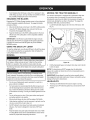
Locatethe hydrostaticbypassrod in the rearof the tractor.See
Fig. 10.
iMPORTANT: Inthe ReverseCautionModetheenginewill automaticallyshut off ifthe PTOisengagedwith the speedcontrol lever
in positionfor reversetravelwith the ignitionkeyin the NORMAL
MOWINGposition.
USING THE DECK LIFT LEVER
Toraisethe cuttingdeck,movethe deck lift levertothe left,then place
itin the notchbest suitedfor yourapplication.Referto SettingThe
CuttingHeightearlierinthis section.
MOWING
Tohelp avoidbladecontactor a thrownobject injury,keepbystanders, helpers,childrenand pets at least 75 feet fromthe machine
whileit is in operation.Stop machineif anyoneentersthearea.
Figure 10
2.
Thefollowinginformationwill be helpfulwhenusingthe cuttingdeck
with yourtractor:
NOTE: Thetransmissionwill NOTengagewhenthe hydrostatic
bypassrod is pulledout. Returnthe rodto its normalpositionprior to
operatingthe tractor.
Planyour mowingpatternto avoiddischargeof materialstoward
roads,sidewalks,bystandersand the like.Also, avoiddischarging
materialagainsta wallor obstructionwhich maycausedischarged
materialto ricochetbacktowardthe operator.
•
•
•
•
•
•
•
Pullthe hydrostaticbypassrod outward,thendownand to the left,
to lock it in place.
iMPORTANT: Neverattemptto movethe tractormanuallywithout
first engagingthe hydrostaticreliefvalve.Doingso will resultin serious
damageto thetractor'stransmission.
Do not mowat high groundspeed,especiallyif a mulch kit or
grasscollectoris installed.
For best resultsit is recommendedthat the firsttwo laps be cut
with the dischargethrowntowardsthe center.Afterthe first two
laps, reversethe directionto throwthe dischargeto the outside
for the balanceof cutting.This will givea betterappearanceto the
lawn.
Do notcut thegrass too short.Shortgrass invitesweedgrowth
and yellowsquicklyin dry weather.
Mowingshouldalwaysbe done withthe engineat full throttle.
Underheavierconditionsit may be necessaryto go back overthe
cut area a secondtime to geta cleancut.
Do NOTattemptto mow heavybrushand weedsand extremely
tall grass.Yourtractoris designedto mowlawns,NOTclear
brush.
Keepthe bladessharpand replacethe bladeswhenworn.Refer
to CuttingBladesin the Serviceand Maintenencesectionof this
manualfor properblade sharpeninginstructions.
17
HEADLIGHTS
•
The lampsare ONwheneverthe tractor'sengineis running.
•
The lampsturn OFFwhenthe ignitionkey ismovedto the STOP
position.
MAINTENANCE
Beforeperforminganytypeof maintenance/service,
disengageall
controlsand stoptheengine.Waituntilall movingpartshavecometo
a completestop.Disconnectsparkplugwireandgrounditagainstthe
enginetopreventunintendedstarting.Alwayswearsafetyglassesduring
operationor whileperforminganyadjustments
or repairs.
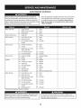
BeforeEachUse
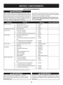
Followthe maintenanceschedulegivenbelow.This chart describes
serviceguidelinesonly. Usethe ServiceLog columnto keeptrack
of completedmaintenancetasks.To locate the nearest Parts &
Repair Service Centeror to scheduleservice,simplycontact
1-800-4-MY-HOME®.
4.
Check
Fingerguard
5.
6.
Clean
Clean
7.
EngineOil
8.
Change
9.
Hood/Dash air vents
12. Clean
13. Clean
1.
2.
Engineoil level
Mufflerarea and controls
3.
In the FirstFive Hours
Every 10 Hours
10. Batteryterminals
11. Deckspindlesand idler
bracket
Every25 hours
SCHEDULE
15. Air filter'sprecleaner*
16. Air filter*
17. Midsteeringarms,pivot
shafts,and axles
14. Lubricate
20. Clean
21. Clean
22. Lubricate
18. Frontwheelbearings
19. Frontdeck wheels
23. Lubricate
24. Lubricate
Every50 hours
25. Engineoil/Oil filter
26. Muffler
27. Change/Replace
28. Check
Annually
29. Air filter
36.
37.
38.
39.
30. Air filter'spre-cleaner
31. Sparkplug
32. Air coolingsystem*
33. Fuelfilter
34. SteeringGears
35. RearWheels
BeforeStorage
Replace
Replace
Replace
Clean
40. Replace
41. Clean
42. Removeand greaseaxles
43. Hood/Dash air vents
50. Clean
44. Batteryterminals
51. Clean
52. Lubricate
45. Midsteeringarms,pivot
shafts,and axles
46. Frontwheelbearings
47. Frontdeck wheels
53. Lubricate
54. Lubricate
48. Deckspindlesand idler
bracket
55. Lubricate
49. Pedalpivot points
56. Lubricate
*Servicemorefrequentlyunderdustyconditions.
Beforeperformingany maintenanceor repairs,disengagethe PTO
(Blade EngageLever),engagethe parkingbrake,stopthe engine
and removethe key to preventunintendedstarting.
If the enginehasbeen recentlyrun,the engine,mufflerand surroundingmetalsurfaceswill be hotand cancause burnsto the skin.
Exercisecautionto avoidburns.
18
ENGINE MAINTENANCE
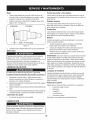
Changing
Checking
The engineoil shouldbe changedin the first 5 hoursand thenevery
50 hoursor once a season.Tochangethe engineoil, proceedas
follows:
the Engine
Oil
Onlyuse high qualitydetergentoil ratedwith APIserviceclassification
SF,SG,SH, or SJ, Selectthe oil's SAEviscositygradeaccordingto
the expectedoperatingtemperature.Followthe chart below.
Althoughmulti-viscosityoils (5W20,10W30,etc.)improvestarting
1.
2.
in coldweather,they will result in increasedoil consumptionwhen
usedabove32°E Checkyour engineoil levelmorefrequentlyto avoid
32°F
_War me'_r
4.
Removethe oil drain plug,The oil will begin todrain out of the
engine.
5.
After the oil hasfinisheddraining,replacethe oil drain plugand
tighten.Be carefulnot to overtighten.
Removethe oil drain sleeveand storefor later use.
7.
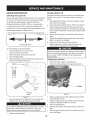
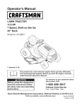
Tocheckthe engineoil, proceedas follows:
•
Ensurethat the tractoris on a levelsurface.
•
1.
Cleantheoil fill area of anydebris.
Removethedipstickand wipe with a clean cloth.
2.
3.
Insertand tightendipstick.
Removethedipstickand checkthe oil level.It shouldbe at the
Fullmark on the dipstick.See Figure11.
With engineOFF but still warm,disconnectsparkplug wireand
keepit awayfrom sparkplug.
Removethe oil fill cap/dipstickfrom theoil fill tube. See Figure11.
Clipthe oil drain sleeve(packedwith this manual)ontothe oil
drain port. Routethe oppositeend of the sleeveintoan appropriate oil collectioncontainerwith a capacitygreatenoughto collect
the usedoil.
6.
Oil Viscosity Chart
Oil
3.
possibleenginedamagefrom runninglowon oil.
f'_older _
Engine
Refillthe enginewith newmotoroil untilthe oil levelon the
dipstick readsFULL.Replacetheoil fill cap/dipstick.
Usedoil is a hazardouswasteproduct.Disposeof usedoil properly.
Do notdiscardwith householdwaste.Checkwith your localauthorities or or contact 1-800-4-MY-HOME
for a list of safe disposal/
recyclingfacilities.
Changing
f
Dipstick-_
the Oil Filter
1.
Drainthe oil fromthe engineas describedabove.
2.
Removethe oil filter and disposeof properly.See Figure12.
Oil Drain
Valve
Oil Drain
Sleeve
Figure12
J
Figure11
If low,add oil slowlyintothe engineoil fill. Do notoverfill.After
addingoil, wait one minuteand then recheckthe oil level.
3.
Beforeyou install the newoil filter, lightly lubricate the oil filter
gasketwith fresh,cleanoil.
4.
Installthe oil filter byhand untilthe gasketcontactstheoil filter
adapter,then tightenthe oil filter 1/2to 3/4 turns.
Add oil as describedabove.
5.
Donotoverfill.Overfillingwith oil maycausethe engine to not start,
hard starting,or engine smoking.If overthe FULLmark on the
dipstick,drain oil to reduceoil levelto FULL markon dipstick.
5.
Replaceandtightendipstick.
19
6.
Startand runthe engine.Asthe enginewarmsup,checkfor oil
leaks.
7.
Stoptheengineand checkthe oil level.It shouldbe at the FULL
markon the dipstick.
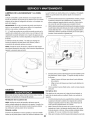
Fuel Filter
Air Cleaner
Iffilters,or coversare notinstalledcorrectlyseriousinjuryor death
could resultfrom backfire.Do notattemptto startthe enginewith
them removed.
Gasolineand itsvaporsare extremelyflammableand explosive.Fire
or explosioncan causesevereburnsor death.
•
•
Keepgasolineawayfrom sparks,open flames,pilotlights,heat,
and otherignitionsources.
Checkfuel lines, tank,cap, and fittingsfrequentlyforcracks or
leaks.Replaceif necessary.
•
Beforereplacingthe fuelfilter,drain the fueltank as per the
instructions
below.
•
Do notdrain fuel whenthe engine ishot. Allowthe engine
adequatetime to cool. Drainfuel intoan approvedcontainer
outdoors,away fromopen flame.
•
Drainanylarge volumeof fuelfrom the tank by disconnectingthe
fuel linefrom the in-linefuelfilter near theengine.
Removethe fuel line from the In-lineside (sidetowardsthe fuel
tank)of thefuel filter.
Replacementparts mustbe the sameand installedin the same
positionas theoriginal parts.
•
•
Donot use pressurizedair or solventsto cleanthe air cleaner
cartridge.
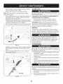
The air filter systemuses a cylindricalcartridge.
1.
Removethe fasteners(A) and the air filter cover (B). See Figure
14.
2.
To removethe filter (C), liftthe end of the filterand then pull the
filter off the intake(D).
3.
To loosendebris,gently tapthe filter on a hardsurface.If thefilter
A
B
•
•
If fuel spills,wait until itevaporatesbeforestartingengine.
Beforereplacingthe fuelfilter,drain the fueltank. Otherwisefuel
can leakout and causea fireor explosion.
To Drainthe fuel:
1.
Locatethefuelfilter,whichis routedon the leftsideofthe engine
betweenthe fueltankand the carburetor,and maybe attachedto
theenginewitha tie strap.Cutthetie strap,ifpresent,then pinch
thein-lineclampon thefuelfilterwith a pairof pliers,slidethe
clampup thefuelline.Pullthe fuellinefreefrom thefilterand place
theopenend of the lineintoan approvedcontainerto drainthefuel.
To changethe fuel filter:
1. Usepliersto squeezethe tabs on the otherclamp (theout-line
sideof the fuel filter),thenslidethe clamp awayfromthe fuel filter.
Twistand pull the fuellineoff of the fuelfilter.See Figure13.
2. Checkthe fuel linesfor cracksor leaks.Replaceif necessary.
3.
4.
Replacethe fuel filter withan originalequipmentreplacement
filter.Call1-800-4-MY-HOME®to purchasethe originalequipment replacementfilter.
J
Figure14
4.
Securethe fuel lineswith the clamps.
5.
Clamp
Fuel
Line
Tab
J
Figure13
2O
is excessivelydirty,replacewith a newfilter.
installthe filter on the intake.Pushthe end of the filter intothe
baseas shown.Makesurefilter fits securelyin the base.
installair filter cover and securewith fasteners.
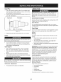
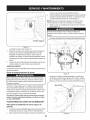
Spark
1.
LUBRICATION
Plug
Cleanareaaroundthe spark plug base.Do notsandblastspark
plug,Sparkplug shouldbe cleanedby scrapingor wire brushing
and washingwith a commercialsolvent
Beforelubricating,repairing,or inspecting,alwaysdisengagePTO
(Blade EngageLever),moveshift leverinto neutralposition,set
parkingbrake,stopengine and removekey to preventunintended
starting.
Removeand inspectthe spark plug.Checkgap to makesureit is
set at .030".See Figure15.
Electrode
Porcelain
Pivot Points
& Linkage
Lubricateall the pivot pointson the drivesystem,parkingbrakeand lift
linkageat leastonce a seasonwith lightoil.
Rear Wheels
The rear wheelsshouldbe removedfrom theaxles oncea season.
Lubricatetheaxles and the rims wellwith an all-purposegreasebefore
re-installingthem.
Front Axles
_.030
(.76 mm) gap
Eachend of thetractor'sfront pivotbar maybe equippedwith a grease
fitting. Lubricatewith a greasegun after every 25 hoursof tractor
operation.
\
Figure15
3.
Replacethespark plug (Champion®RC12YC)once a season.
Battery
The batteryis sealedand is maintenance-free.Acidlevelscannot be
checked.
Muffler
Alwayskeepthe batterycablesand terminalscleanand free of
corrosivebuild-up.
After cleaningthe batteryand terminals,applya lightcoat of
petroleumjelly or greaseto bothterminals.
Temperatureof mufflerand nearbyengineareasmayexceed 150° F
(65°0).Avoidcontactwith these areas.
•
inspectmufflerperiodically,and replaceif necessary.Replacement partsfor the mufflermustbe the sameand installedin the
samepositionas the originalparts.
Clean
•
Alwayskeepthe rubberbootpositionedoverthe positiveterminal
to preventshorting.
iMPORTANT: if removingthe batteryfor any reason,disconnectthe
NEGATIVE(Black)wirefrom its terminalfirst, followedby the POSITIVE (Red)wire.When re-installingthe battery,alwaysconnectthe
POSITIVE(Red)wire to its terminalfirst, followedbythe NEGATIVE
(Black)wire. Be certainthat the wiresare connectedto the correct
terminals;reversingthemcouldchangethe polarityand result in
damageto yourengine'salternatingsystem.
Engine
Dailyor beforeeveryuse, cleangrass,chaff or accumulated
debrisfromengine.Keeplinkage,spring,and controlsclean.
Keeparea aroundand behindmufflerfreeof any combustible
debris.
Keepingenginecleanallowsair movementaroundengine.
•
Engineparts shouldbe keptcleanto reducethe risk of overheating and ignitionof accumulateddebris.
Cleaning
Cleanthe batteryby removingit from the tractorand washingwith
a bakingsodaand watersolution.If necessary,scrapethe battery
terminalswith a wirebrushto removedeposits.Coatterminalsand
exposedwiringwith greaseor petroleumjellyto preventcorrosion.
Do notuse waterto cleanengineparts.Watercouldcontaminatefuel
system.Use a brushor dry cloth.
Carburetor
•
Battery
Battery
Failures
Somecommoncausesfor batteryfailureare:
incorrectinitialactivation
Adjustment
Thecarburetoron this engineisnot adjustable.
Overcharging
Freezing
Undercharging
Corrodedconnections
These failuresare NOTcoveredbyyourtractor'swarranty.
21
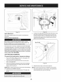
CLEANING THE ENGINE AND DECK
2.
Anyfuel or oil spilledon the machineshouldbe wipedoff promptly.Do
NOTallowdebristo accumulatearoundthe coolingfins of the engine
or on anyother partof the machine.
IMPORTANT: The useof a pressurewasherto cleanyourtractoris
NOT recommended.It maycause damageto electricalcomponents,
spindles,pulleys,bearingsor the engine.
A screwplug can be foundon yourtractor'sdeck surfaceas seenin
Fig. 16.This plug can be replacedwith a waterport to be usedas part
of a separately-available
deck wash system.
The DeckWash SystemTM is usedto rinsegrassclippingsfrom the
deck'sundersideand preventthe buildupof corrosivechemicals.
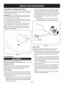
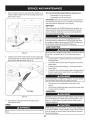
3.
Measurethedistancefromthe front of the bladetip to the ground
and the rearof the bladetip to theground.Thefirst measurement takenshouldbe between1A"and 3A"less thanthe second
measurement.Determinethe approximatedistancenecessaryfor
properadjustmentand proceed,if necessary,to the next step.
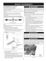
Locatethe flangelock nut on the front sideof the stabilizer
bracket.See Fig. 17.
Tightenthe flangelock nut to raisethe frontof the deck;
Loosentheflange lock nutto lowerthefront of thedeck.
f
NOTE: A deck wash systemcan be purchasedthroughthe retail
locationin which youpurchasedthis tractor.For moreinformation,
simplycall 1-800-4-MY-HOME®.
/
/
/
=
Figure17
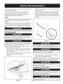
Side to Side
If the cuttingdeck appearsto be mowingunevenly,a sideto side
adjustmentcan be performed.Adjustif necessaryas follows:
1.
With the tractorparkedon a firm, levelsurface,placethe deck lift
leverin the secondfromthe top notch (secondhighestposition)
and rotatebothbladessothat theyare perpendicularwith the
tractor.
2.
Measurethedistancefromthe outsideof the left bladetip to the
groundand the distancefrom the outsideof the rightblade tip to
the ground.Bothmeasurementstaken shouldbe equal.If they're
not, proceedto the nextstep.
3.
Loosen,but do NOTremove,the hexcap screwon the left deck
hanger bracket.See Fig. 18.
Balancethedeck by usinga wrenchto turn theadjustmentgear
(foundimmediatelybehindthehex cap screwjust loosened)
clockwise/upor counterclockwise/down.Thedeck is properly
balancedwhen bothbladetip measurementstakenearlier are
equal.
Retightenthe hex cap screwon the left deck hangerbracket
when properadjustmentis achieved.
Figure16
ADJUSTMENTS
Neverattemptto makeanyadjustmentswhilethe engineis running,
exceptwherespecifiedin the operator'smanual.
Leveling
the Deck
4.
NOTE: Checkthe tractor'stire pressurebeforeperforminganydeck
levelingadjustments.Referto Tires in the Servicesectionof this
manualfor moreinformationregardingtire pressure.
Front To Rear
Thefront of the cuttingdeck is supportedby a stabilizerbar that can
be adjustedto levelthe deckfrom front to rear.Thefront of the deck
shouldbe between1A-inch
and 3A-inchlowerthan the rear of thedeck.
Adjustif necessaryas follows:
1.
Withthe tractorparkedon a firm,levelsurface,placethe leverfor
lifting the platformon the secondto the top notch(secondhighest
position)and rotatethe bladeas close to the dischargechannel
that is parallelto the tractor.
22
5.
He× Cap Screw
'_.
._
Figure19
Lookingat thecuttingdeck from the left side of the tractor,locate
the bow-tiepin that securesthedeck support rod on the rear
Idt sideof the deck. See Fig.20. Removethe bow-tiepin that
securesthedeck support rod,and carefullyremovethe deck
supportfromthe deck lift arm.
Figure18
Seat Adjustment
Referto the Assemblysectionof this manualfor seat adjustment
instructions.
Parking
Brake
Adjustment
F
Neverattemptto adjustthe brakeswhiletheengine is running.
AlwaysdisengagePTO,moveshift leverintoneutralposition,stop
engineand removekeyto preventunintendedstarting.
Bow-Tie Clip
If thetractordoes notcome to a completestop whenthe brakepedal
is completelydepressed,or if the tractor'srearwheelscan roll with the
parkingbrakeapplied,the brakeis in needof adjustment.Contactthe
nearest Sears Service Center to haveyourbrakesproperlyadjusted.
Tolocatethe nearest Parts& Repair Service Center or to schedule
service, contact 1-800-4-MY-HOME®.
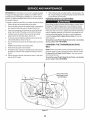
CUTTING
DECK REMOVAL
To remove
the cutting
1.
2.
3.
deck,
proceed
as follows:
Placethe PTO(Blade Engage)leverin the disengaged(OFF)
position and engagethe parkingbrake.
Lowerthe deck by movingthe deck lift lever intothe bottom
notch on the rightfender.
Removetheself-tappingscrew(A) that securesthe belt-keeper
rod from aroundthe tractor'sPTOpulley,thenremovethe belt
keeperrod (B). See Fig. 19.
6.
NOTE: Makea mentalnotewhat holethe otherend of the belt-keeper
rod isinsertedin for reinstallationpurposes.
4.
Removethebelt (C) from aroundthetractor'sPTOpulley.See
Fig. 19.
Avoidpinchinginjuries.Neverplaceyourfingers on the idler springor
betweenthe belt and a pulleywhile removingthe belt.
23
Repeatthe abovestepson the tractor'srightside.
NOTE: The bow-tieclips shouldbe re-installedfrom the top down.
7.
Movethe deck lift leverintothe top notchon the rightfenderto
raisethe deck lift arms up and out of the way.
8,
Removethe bow-tiecotterpin securingthe deck stabilizerrod to
thedeck. Slidethe deck lift rodfrom the mountingbracketon the
deck asseen in Fig.21.
.............
/1;_,_
.........................
The recommended
operating
tire pressure
•
Approximately10psi for the rear tires
•
Approximately14psi for the fronttires
is:
IMPORTANT=Referto the tire sidewallfor exacttire manufacturer's
recommendedor maximumpsi. Donot overinflate.Uneventire pressurecould causethe cuttingdeckto mowunevenly.
/ ..............................
BATTERY
CaliforniaProposition65 WARNING!Batteryposts,terminals,and
relatedaccessoriescontainlead and lead compounds,chemicals
knownto the State of Californiato causecancer and reproductive
harm.Wash handsafter handling.
If removingthe battery,disconnectthe NEGATIVE(Black)wire
from its terminalfirst, followedbythe POSITIVE(Red) wire.When
relinstallingthe battery,alwaysconnectthe POSITIVE(Red)wire to
I ts termna f rst,fo owedby the NEGATVE (Back) w re.
JUMP STARTING
_,.,
j2
Neverjump starta damagedor frozenbattery.Be certain thevehicles
do not touch,and ignitionsare off. Do notallowcable clampsto
touch.
Figure21
.
Carefullyremovethe PTOcablefrom the rearof the cuttingdeck
by removingthe bow-tiecotterpin which securesit. Removethe
springfromthe deck idler bracket.See Fig.22.
1.
f
2.
3.
4.
Connectpositive(+)cableto positivepost (+)of yourtractor's
dischargedbattery.
Connecttheotherend of thecableto the (positive+) postof the
jumperbattery.
Connectthesecondcable (negative-) to theother post of the
jumperbattery.
Connecttheotherend of thenegativecableto the engineblockof
the tractor,away fromthe battery.Attachto an unpaintedpartto
assurea good connection.
If thejumper batteryis installedon a vehicle (i.e.car, truck),do NOT
startthe vehicle'senginewhenjump startingyourtractor.
5.
6.
PTOCable
_
Start the tractor(as instructedearlierin this sectionof this
manual).
Set the tractor'sparkingbrakebeforeremovingthejumpercables,
in reverseorderof connection.
CHARGING
J
Figure22
Batteriesgive off an explosivegas whilecharging.Chargethe batteryI
in a wellventilatedareaand keepaway froman openflame or pilot
ght as on a waterheater,spaceheater,furnace,c othes dryeror |
othergas appliances.
10. Gentlyslidethe cuttingdeck (fromthe left side)out from
underneaththe tractor.
J
TIRES
Whenchargingyourtractor'sbattery,useonlya chargerdesignedfor I
12Vlead-acidbatteries.Readyourbatterychargers Owners Manual
priorto chargingyourtractors battery.Alwaysfollowits instructions I
land heed ts warnngs.
j
Neverexceedthe maximuminflationpressureshownon the sidewall
of tire.
24
If yourtractorhasnot been putinto usefor an extendedperiodof time,
chargethe batteryas follows:
1. Setyour batterychargerto delivera max of 10amperes.
.
4.
If yourbatterychargeris automatic,chargethe batteryuntilthe
chargerindicatesthat chargingis complete.If the chargeris not
automatic,chargefor no fewerthaneight hours.
FUSE
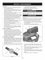
Removethe hexflangenut that securesthe bladeto the spindle
assembly.See Fig.23.
To properlysharpenthe cuttingblades,removeequalamounts
of metalfrom bothendsof the bladesalongthe cuttingedges,
parallelto the trailingedge,at a 250.to 300angle.Alwaysgrind
eachcutting bladeedge equallyto maintainproperblade balance.
See Fig.24.
One 20 AMPfuse is installedin yourtractor'swiringharnessto protect
the tractor'selectricalsystemfrom damagecaused byexcessive
amperage.
If theelectricalsystemdoesnot function,or yourtractor'senginewill
not crank,first checkto be certainthat the fuse hasnot blown.It can
be foundat the rear of the unit, underneaththefenderlocatedby the
battery.
Alwaysusea fuse with the sameamperagecapacityfor replacement.
CUTTING
BLADES
Shutthe engineoff and removeignitionkey beforeremovingthe
cuttingblade(s)for sharpeningor replacement.Protectyourhands
by usingheavygloveswhengraspingthe blade.
Figure 24
Periodicallyinspectthe bladeand/or spindlefor cracks or damage,
especiallyafter you'vestrucka foreignobject. Donot operatethe
machineuntil damagedcomponentsare replaced.
If the cuttingedge of the bladehas previouslybeen sharpened,or if
any metalseparationis present,replacethe bladeswith newones.
Toremovethe blades,proceedas follows.
1.
2.
f
Removethedeck from beneaththe tractor,(referto CuttingDeck
Removalearlier in this section)thengently flip thedeck overto
exposeits underside.
Placea blockof woodbetweenthe centerdeck housingbaffle
and the cuttingbladeto act as a stabilizer.
See Fig. 23.
A poorlybalancedbladewill causeexcessivevibration,maycause
damageto the tractorand/or resultin personalinjury.
5.
Testthe blade'sbalanceusinga blade balancer.Grind metal
from the heavyside untilit balancesevenly.
NOTE: Whenreplacingthe blade,be sureto installthe blade with the
sideof the blademarked"Bottom" (or with a part numberstampedin
it)facing the groundwhenthe moweris in the operatingposition.
Usea torquewrenchto tightenthe bladespindlehexflangenut to
between70 Ibs-ftand 90 Ibs-ft.
CHANGING
THE DECK BELT
Be sureto shut the engineoff, removeignitionkey,disconnectthe
Ispark plug wire(s)and ground againstthe engineto preventuninltended startingbeforeremovingthe belt.
All belts on yourtractorare subjectto wearand shouldbe replacedif
any signsof wearare present.
iMPORTANT: The V-beltfoundon yourtractoris speciallydesigned
to engageand disengagesafely.A substitute(non-OEM)V-beltcan
be dangerousby notdisengagingcompletely.Fora properworking
machine,useidenticalequipmentbeltsas listedin the parts pagesof
this Operator'sManual.
11. Whileholdingthe belt and pulleytogether,rotatethe pulleyto the
left. Continueholdingand rotatingthe pulleyand belt untilthe belt
is fully rolledinto the PTOpulley.
PARKING
Tochangeor replacethe deck belt on yourtractor,proceedas follows:
1. Removethe deck as instructed
earlier inthis section.
2.
3.
4.
5.
6.
7.
8.
Removethe beltcoversfrom the spindlepulleysby removingthe
hexscrewsthat fastenthecoversto the deck.See Fig. 25,
It mayalso be necessaryto loosenthe hex nuton the left idler
pulleyto getthe belt off the pulleyand aroundthe beltguard.
BRAKE
ADJUSTMENT
Neverattemptto adjustthe brakeswhiletheengineis running.Always
disengagePTO(BladeEngageLever),moveshiftleverintoneutral
position,stopengineand removekeyto preventunintendedstarting.
If the tractordoesnot cometo a completestop whenthe clutch-brake
pedal is completelydepressed,or if the tractor'srearwheelscan roll
with the parkingbrakeapplied,the brakeis in need of adjustment.
Contactthe nearest Parts & Repair Service Center to haveyour
brakesserviced.
Carefullyremovethe deck beltfrom aroundthe two spindle
pulleysand thetwo deck idler pulleys,See Fig, 25,
Toplacethe newbelt, begin by routingthe belt aroundthe two
outerspindlepulleysas shownin Fig, 25,
To locatethe nearest Parts& RepairService Center or to schedule
service,contact1-800-4-MY-HOME®.
Thenroutethe beltaroundthe two deck idlerpulleysas shownin
Fig. 25.
Retightenthe belt keeperrodloosenedearlier.
Remountthebelt guardsremovedearlier,
CHANGING
BELT
THE TRANSMISSION
NOTE: Severalcomponentsmust be removedand specialtools (i.e.
air/impactwrench)in order to changethetractor'sdrivebelt. Contact
the nearest Parts & Repair Service Center to haveyourtransmission drivebelt serviced.
9.
Re-installthedeck, makingsurethe belt remainsroutedaround
the pulleysas instructed.
Thecompletebelt routingisshownin
Fig. 25.
10. Pull the rightside ofthe belt,and placethe narrowV side of the
belt intothe PTOpulley.
To locatethe nearest Parts& RepairService Center or to schedule
service, contact 1-800-4-MY-HOME®.
This portion of the
belt routes around
the PTO Pulley
He× Washer
Screws
Belt Cover
Belt Guard
_
DRIVE
_oo Deck,d,er Pu,,ey
Figure 25
26
Neverstorelawntractorwith fuel in tank indoorsor in poorly
ventilatedareaswherefuel fumesmay reachan open flame,spark,
or pilot lightas on a furnace,water heater,clothesdryer,or gas
appliance.
PREPARING
THE ENGINE
DRAiNiNG
IMPORTANT:Fuelleft in thefuel tank duringwarm weatherdeterioratesand will causeseriousstartingproblems.
To preventgumdepositsfromforminginsidethe engine'scarburetor
and causingpossiblemalfunctionof theengine,thefuel systemmust
be eithercompletelyemptied,or the gasolinemustbe treatedwith a
stabilizerto preventdeterioration.
1. If usingafuel stabilizer:
a.
Readthe productmanufacturer'sinstructionsand recommendations.
b.
Add to clean, freshgasolinethe correctamountof stabilizer
for the capacityof the fuel system.
Fillthe fueltank with treatedfuel and run the enginefor 2-3
minutesto get stabilizedfuel intothe carburetor.
c.
2.
Reconnectthe fuel lineand run the engineuntil it starts to
falter,thenuse thechoketo keeptheengine runninguntilall
fuel in thecarburetorhas beenexhausted.
d.
Disconnectthefuel lineand drain any remaininggasoline
from the system.
Gasolineis a toxicsubstance.Disposeof gasolineproperly.Contact
your localauthoritiesfor approveddisposalmethods.
3.
Locatethe fuel filter,which is locatedon the left sideof the
engine,and maybe attachedto the enginewith a tie strap.
2.
Cutthe tie strap,if present,then pinchthe in-lineclamp on the
fuel filter with a pair of pliers,slidethe clamp up the fuel line.
Pullthe fuel line freefrom the filter and placethe open end of the
lineintoan approvedcontainerto drain the fuel.
PREPARING
Gasolineis extremelyflammableand can be explosiveundercertain
conditions.Draingasolinebeforestoringthe equipmentfor extended
periods.Drainfuel only intoan approvedcontaineroutdoors,away
from an openflame.Allowengineto cool. Extinguishcigarettes,
cigars,pipes, and othersourcesof ignitionprior to drainingfuel.
Storegasolinein an approvedcontainerin safe location.
c.
1.
3.
If emptyingthe fuel system:
a. Donot drainfuel whenthe engineis hot. Allowthe engine
adequatetime to cool. Drainfuelinto an approvedcontainer
outdoors,awayfrom open flame.
b. Drainany largevolumeof fuel from thetank bydisconnecting thefuel linefrom the in-linefuel filter nearthe engine.
See the completeinstructionsfor DrainingThe Fuellaterin
this section.
Removethe sparkplug and pour one (1) ounceof engineoil
throughthe sparkplug hole intothe cylinder.Cranktheengine
severaltimesto distributethe oil. Replacethe spark plug.
27
THE FUEL
THE LAWN TRACTOR
1.
Cleanand lubricatetractorthoroughlyas describedin the lubrication instructions.
2.
3.
Donot usea pressurewasheror gardenhoseto cleanyour unit.
Storemowerin a dry,cleanarea. Do notstore nextto corrosive
materials,such as fertilizer.
Enginefails to start
1.
2.
PTO/BladeEngageleverengaged.
Parkingbrakenotengaged.
1.
2.
Placeleverin disengaged(OFF) position.
Engageparkingbrake.
3.
4.
3.
4.
Connectwire(s)to sparkplug(s).
Placethrottleleverto FASTposition.
5.
Sparkplugwire(s) disconnected.
Throttlecontrollevernot in correctstarting
position.
Chokenotactivated
5.
Pull theCHOKEcontroloutward.
6.
7.
Fueltank empty,or stale fuel.
Blockedfuel line.
6.
7.
Filltank with clean, fresh(less than30 daysold) gas.
Replacethe fuel line and replacefuel filter.
8.
9.
Faultyspark plug(s).
Engineflooded.
8.
9.
Clean,adjustgap or replaceplug(s).
Crankenginewith throttlein FASTposition.
1.
2.
3.
Unit runningwith CHOKEactivated.
Sparkplugwire(s) loose.
Blockedfuel line or stalefuel.
1.
PushCHOKEcontrol in.
2.
Connectspark plugwire(s).
3.
4.
Ventin gas cap plugged.
4.
Replacethe fuel line;fill tank with clean,fresh
gasolineand replacefuel filter.
Clearventor replacecap if damaged.
5.
6.
Wateror dirt in fuel system.
Dirtyair cleaner.
5.
6.
Drainfueltank. Refillwith clean,fresh gasoline.
Replaceair cleanerpaperelementor cleanfoam
pre-cleaner,if equipped.
Engineoverheats
1.
2.
Engineoil levellow.
Air flow restricted.
1.
2.
Fillcrankcasewith properamountand weightof oil.
Cleangrass clippingsand debrisfromaroundthe
engine'scoolingfins and housing.
Enginehesitatesat high RPM
1.
Sparkpluggaptoo close.
1.
Removesparkplug and resetthe gap.
Engineidles rough
1.
2.
Sparkplugfouled,faultyor gap too wide.
Dirtyair cleaner.
1.
2.
Replacesparkplug.Set pluggap.
Replaceair cleanerelementand/orclean precleaner.
Excessivevibration
1.
2.
Cuttingbladelooseor unbalanced.
Damagedor bentcuttingblade.
1.
2.
Tightenbladeand spindle.
Replaceblade.
Mowerwill not mulchgrass
1.
Enginespeedtoo low.
1.
Placethrottlein FAST(rabbit)position.
2.
3.
Wetgrass.
Excessivelyhigh grass.
2.
3.
Do notmulch whengrass is wet.
Mowonce at a highcuttingheight,then mowagain
at desiredheightor makea narrowercuttingswath.
4.
Dullblade.
4.
Sharpenor replaceblade.
1.
2.
Decknot leveledproperly.
Dullblade.
1.
Performside-to-sidedeck adjustment.
3.
Uneventire pressure.
2.
3.
Sharpenor replaceblade.
Checktire pressurein all fourtires.
Enginerunserratically
Unevencut
NEED MORE HELP?
Youll
fkld t_e answe_
Find this
and all your
Get answers
from
information
maoage
other
our team
,, Get a personalized
,, Find
_"ct mo_e o_ maoage_nyl]o_ne
product
of home
maintenance
and tools
_
manuals
online.
experts.
plan for your
to help with
home
home
b_*oug_t t_ _'ou by Sea_'s
28
home.
projects.
co_n - br
kee!
777X44366
777X44365
LEFT
777X43688
777122773
Place On Gas Tank
Close To intake
DONoT
USEE_50_FU_
CO.TAm=,C
MO.E
THAN 10% ETHANOL
Centered On SteeringWheel
With Only Half Of The Split
Sacking Removed For Easy
Removal
RIGHT
STEERING
OPERATION
STEERING
REF: 751 B278857
(Supplied By Manufacturer)
Place On Engine
WHEEL
MOU"TING
HAROWARE
U"DER
CAP,
BEFORE
If BJ label Has
SECURE
WHEEL
TO
SHIFT ICCORDING
important Emmisions Infor ..........
marion Place
Label Here
TO"ANUlL
777S33583
REE 777D14476 (QTY 3)
IN-MOLD ON SOTH SIDES
OF HOOD SCOOP AND
FRONT GRILLE
777D14479
On Back Of Seat
777123364
Place On Fender With
The PTO Side Next To
The Pto And The Deck
Height Next ToThe
Deck Height
777D14483
Lower Left Hood Side
Place OverWeld Marks
777122494
777D14482
777S30018
(QTY 2) 777D14490
On Lower Dash Area
Both Sides
777S30503
Lower Right Hood Side
Place OverWeld Marks
777122456
777J23365
777122470
29
Craftsman
IViodel 247.28905
11\
39
43
/
44
®
@
/
41
3O
Craftsman
Ref,
No,
[
IViodel 247.28905
Part No,
Description
Ref,
No,
I
Part No,
Description
1
925-1649
Bulb Socket
24
711-0736
Ferrule,
2
683-04619-4043
Hood
25
712-04065
Nut, Hex Flange
Screw, 5/16-18
26
714-04040
Cotter
Assembly
1/4-20 x 1.00
3
710-04484
4
710-0599
Hex Washer
27
936-0133
Flat Washer,
5
712-0292
Tin Clip Nut, 1/4-20
28
750-04465
Flange
Spacer
6
710-0751
Hex Screw,
29
783-04862
Speed
latch
7
710-05108
Screw, 1/4 x .750
30
710-0604A
Self-Tap
8
712-04064
Nut, Hex Flange
31
710-0895
Hex Screw,
9
731-07668
Grill
32
712-04063
Nut, Hex Flange
10
731-07458
Headlight
Lens, RH
33
731-04945
Steering
II
731-07459
Headlight
Lens, LH
34
783-04892B-0637
Dash
12
731-07460
Dash Collar
35
683-04448-0637
Battery
13
731-07670
Hood
LH
36
726-0230
Cable Tie
14
731-07669
Hood
RH
37
747-04430
Speed
15
735-0271A
Bumper
38
751-0555B
1.5 Gallon
16
738-04091A
Shoulder
39
751-0603A
Fuel Cap
17
783-05327B-0637
Left Support
40
783-04584A-0637
Gas Tank Support
18
783-05328A-0637
Right Support
41
731-05265
Choke
x .750
Screw,
1/4-20 x .500
1/4-20 x .620
Scoop,
Scoop,
Insert
Lock, 1/4-20
Screw, 5/16-18
Pivot Bracket
Pivot Bracket
.411 x 1.25 x .100
Screw, 5/16-18
1/4-15
Assembly
Selector
Control
Rod
Bracket
Plug
Lower Grill
42
746-04364
Throttle/Choke
783-06610-0637
Lower Grill Bracket
43
725-04992
Key Switch
21
983-04226
Parking
44
625-04124
Key (2 pack)
22
710-04483
Self-Tap Screw,
45
725-0157
Cable Tie
23
710-3144
Hex Head Screw,
46
925-0963
Headlight
31
Rod
Fuel Tank
783-06598-4043
3/8-16
Lock, 5/16-18
Support
19
1/4-20
Lock, 3/8-16
Pin
20
Brake Lever Assenbly
Insert
Assembly
Module
Bulb
Craftsman
IViodel 247.28905
36
39
22
12
21
28
14
3O
45
38
11
%
2
32
Craftsman
Model
Ref.
No. I
Part No.
247.28905
Description
Ref.
No. I
Part No,
Description
1
683-04155A-0637 Shaft,Lift
24
756-04196A
EngagementPulley
2
712-04065
Nut, HexFlangeinsert Lock,3/8-16
25
747-04857
BeltKeeperRodAssembly
3
714-04040
Bow-TiePin,91,RH
26
710-04484
Screw,Hd.lapp, 5/16-18x .75
4
716-0106A
E-ring,.625Shaft
27
683-04195-0637
SupportBracketAssembly
Grip,Handle
28
683-04601-0637
RiderFrameAssembly
Spring,Lift HandleTorsion
29
710-0134
CarriageScrew,1/4-20x .62
Bolt, Shoulder,.625x .175:3/8-16
30
710-3008
Screw,Hx.Hd.,5/16-18x .75
Bearing,Hex Flange,
31
712-04063
Nut,Hex FlangeInsert Lock,5/16-18
Handle,Lift
32
712-04064
Nut,Hex FlangeInsert Lock,1/4-20
Lift Rod, 13.68
33
912-0429
HexlockNut,5/16-18
5
6
7
720-0311
732-04225
738-04130
8
941-0225
9
747-05296
10
747-04393
11
783-04494C-0637 Arm, DeckLift RH
34
732-04035
Spring,Compress.,1.28x 3.125
783-04711C-0637 Arm, DeckLift LH
35
736-0173
FiatWasher,.28x .74x .063
12
647-04096-0637
PTOHandleAssembly
36
783-04548C-0637 Seat BracketFrame
13
710-04608
Screw,Hx. Hd.,7/16-20x 3.25
37
783-04637-0637
RunningBoardBracket
14
710-0599
Screw,Hd. lapp, 1/4-20x .5
38
783-04753-0637
FrameSupportBracket
15
714-04040
ClickPin
39
783-04869A-0637 BatteryBracket
16
720-04049A
HandleGrip
40
783-05389A-0637 FrameBraceBracket
17
732-04276A
PTOSpring,Extension
41
725-05090
DieHard Battery
18
936-0171
Washer,Fiat,7/16
42
738-1132
Screw,Shoulder,.250x .150
19
736-0322
Washer,Fiat, .450x .250x .164
43
712-0271
Nut,Seres,1/4-20
20
738-04237A
ShoulderScrew,#10-32x .500
44
683-04448-0637
BatteryRod
925-04039
Screw MountInterlockSwitch
725-04363
interlockSwitch
21
741-04119A
PTOBearing
45
22
946-04173C
DeckEngagementCable
46
23
725-04439
12v.Solenoid
33
25
29
23
33
35
34
Craftsman
Ref,
No,
I
Model
247.28905
Part No.
1
617-04024
2
710-0376
3
710-0643
4
710-1309
Description
Ref,
No,
I
Part No,
Description
23
938-04007A-0637
Axle Assembly
LH
Screw, 5/16-18, 1.00, Gr5
24
638-04008P
Axle Assembly
RH
Screw, 5/16-18, 1.00, Gr5, Lock
25
683-0128B-0637
Pivot Bar Axle Assembly
Screw, Mach, 5/16-18, 0.750
26
710-04484
Screw, 5/16-18, 0.750
712-04065
Nut, Flange Lock, 3/8-16, GrF
Gear Assembly,
Steering
5
710-3180
Screw, 5/16-18, 1.75, Gr5
27
6
912-0240
Nut, Jam, 7/16-20, Gr2
28
714-04039
Pin, Cotter, 5/32, 1.25
7
912-0214
Nut, Jam Lock, 3/8-24
29
914-0474
Pin, Cotter, 1/8 x 0.75
736-0341
Push Cap, 3/4
8
712-04063
Nut, Flange Lock, 5/16-18, Grf
30
9
931-0484A
Hub Cap
31
731-04057A
Axle Cap
10
923-0448A
Ball Joint, 7/16-20, Lock
32
736-04228A
Washer, Flat, .781 x 1.59
II
736-0242
Washer, Bell, .340 x .872 x .060
33
738-04128
Screw, Shlder, .500 x 2.380, 3/8-16
12
934-0255
Valve Stem
34
741-0660A
Flange Bearing
13
738-04141
Shoulder
35
747-04299A
Tie Rod
14
738-0919A
Steering
36
783-05326B-0637
Pivot Bar Bracket
631-04028
Steering Wheel,
Screw, 5/16-18
Shaft, 5/8 Spline x 21.86
15
941-04124
Bearing, Flange, Hex 5/8
37
16
941-04454
Plastic Bushing .375 ID x .05 OD
38
731-06825
Cap, Steering
17
747-04298
Drag Link, Steering
39
634-04086-0961
Wheel Assembly
934-04081-4042
Rim
18
948-0389
Cap, 1.25 x .16
40
19
748-04065-0637
Steering,
41
734-1731-0901
Tire, 15 x6x6
20
748-04068
Spacer, .710 ID x .125 OD x .56
42
741-0990B
Flange Bearing
43
741-0516B
Flange Bearing
Block
21
750-04418
Spacer, .322 ID x .625 OD x .21
22
783-04644
Stabilizer
Plate, Gear Segment
35
Standard
Grip
Wheel (Crafts. logo)
Sq. Shoulder
Craftsman
Model
247.28905
2o
12
6,
22
2S\
28..
31 30
32
17
15
/
oi
3G
29
Craftsman
Model
247.28905
Ref,
No,
[
Part No,
Description
1
710-1268
Screw, #10-16 x .375
2
712-04063
Flange Lock Nut, 5/16-18
3
712-04064
Flange Lock Nut, 1/4-20
4
720-0309A
Seat Adjustment
5
726-0201
Speed Nut
6
731-04074
Seat Adjustment
7
732-0499
Compression
8
732-1184
Extension
9
736-0204
Flat Washer, .344 x .62 x .033
10
736-0242
Flat Washer, .340 x .872 x .060
II
736-3019
Flat Washer, .531 x .062 x .134
12
938-0137A
Shoulder
13
938-0296
Shoulder Screw, 5/16-18 x .437 x .268
14
738-0966A
Shoulder
15
783-0209D
Lift Seat Bracket
16
783-0611
Seat Adjustment
17
783-0738D-0637
Seat Pivot Bracket
18
783-0739A-0637
Seat Adjustment
Lever
Selector
Grip
Spacer
Spring, .41 x 1.50
Spring
Screw, .34 x .285:1/4-20
Bolt, .50 x .925:3/8-16
Stop Bracket
19
783-0753
Seat Adjustment
20
757-04125
Low Back Seat
21
710-04483
Screw, 1/4-20 x .500
22
710-04484
Screw, 5/16-18 x .750
23
710-0599
Screw Pan Torx Head, 1/4-20 x .500
24
731-04591A
Cup Holder
25
736-0607
Lock Washer, 5/16
26
783-04587C-4043
Fender
27
783-04843-0637
Lift Adjuster
28
783-1489G0637
Seat Mounting
29
735-04047
Rubber
Foot Pad, LH
735-04048
Rubber
Foot Pad, RH
30
710-0227
Screw, 8-18 x .500
31
726-0279
Insulator
32
925-1303
Outer Seat Spring
33
726-0278
Insulator
34
725-1439
Inner Seat Spring
35
710-0134
Carriage
36
726-04072A
Ratchet Clip, .250 x .500
37
Bracket
Bracket
Plate
Boss Plate
Screw, .62:1/4-20
Craftsman
IViodel 247.28905
f
9
7
4
14
4
10
1
38
Craftsman
Model
247.28905
I
Ref, I
Description
Part No.
1
683-04549-0637
Muffler
2
710-0227
Screw, AB #8-18 0.500
3
710-04683
Tap Screw, 3/8-16 h000
4
710-0642
Tap Screw, 1/4-20 0.750
5
710-1314A
Screw, Socket Head, 5/16-18
6
712-0271
Sems Nut, 1/4-20
7
BS-692236
Exhaust
8
725-0157
Cable Tie, 3/16 X .05 X Z4
9
726-0205
Hose Clamp, .490 Dia.
l0
728-04000
Pop Rivet, .188 Dia X .300 L
II
731-05628
Oil Drain
12
751-0564B
Muffler
13
751-I0349
Low Permeation
14
751-I0353
Long Muffler
Deflector
15
751-I0448B
Briggs Single
Muffler
39
Shield Assembly
x .750
Gasket
Sleeve
Deflector
Fuel Hose, 1/4
Craftsman
Model
247.28905
_37
49
29
31
11
Craftsman
Ref,
No,
[
Model
247.28905
Part No,
Description
1
918-04925
Transmission
2
647-04200
Handle Control
3
647-04202-0637
4
710-0227
5
710-0347
6
7
Ref.
NO. I
32
Drive Assembly
Part No,
735-0239
Description
Foot Pad,4.0
33
736-04263
Lock Washer, TRANS HYDRO
Drive Pedal Assembly
34
736-0430
Flat Washer, .350 x 1.59 x .062
Screw, 8-I 8:0.500
35
736-0607
Lock Washer, 5/16 EXT TOOTH
Hex Screw, 3/8-16 x 1.75
36
736-3010
Flat Washer, .407X.812X.135:HT
710-04484
Screw, 5/16-18 x .750
37
710-0627
Hex Screw, 5/16-24 x .750
710-0514
Screw, 3/8-16 x 1.00
38
738-04430
Shoulder
8
710-0604A
Screw, 5/16-18 x 0.625
39
941-0225
Hex Flange Bearing
9
710-0809
Screw, I/4-20 x 1.250
40
747-04283A
De-clutching
10
710-I026
Hex Screw, I/4-20
41
747-04296A
Brake Rod
II
710-1266
Hex Screw, 5/16-18 x .625
42
747-04407A
Hydro Control
12
710-1335
Hex Screw, #10-24
43
747-05242
Brake Rod
13
710-3008
Hex Screw, 5/16-18 x .75
44
747-05245
Bypass Rod
14
710-3103
Hex Screw, 5/16-18 x 2.00
45
948-0334
Spacer, T-Axle
15
711-04448
Ferrule, 5/16-24 x .312
46
750-04456
Spacer, .260 x .372 x 1.420
16
912-0346
Flange Nut, I/2-20
47
750-0566A
Spacer, .260 x .375 x 1.030 LG
17
712-04063
Flangelock
Nut, 5/16-18
48
750-0802
Spacer, .640 ID X .76 OD X 2.63
18
712-04065
Flangelock
Nut, 3/8-16
49
954-04252
V Belt, 4L SECX 84.17 LG
19
714-04040
Bow-Tie Cotter Pin
50
756-04224
Flat Idler Pulley2.75
20
716-0106A
E-Ring
51
756-04308
Input Pulley
21
720-0311
Handle Grip
52
783-04536B-0637
Support
22
725-04249
Hydro Spring Switch
53
783-04570B-0637
Idler Arm
23
726-0214
Push Cap, 5/8
54
783-04585A
Handle Mounting
24
926-0320
Plate Insulator
Nut
55
783-06551
Hydro Bracket
25
731-05299A
Sleeve, .765 x 1.50
56
783-06558-0637
Belt Support
26
731-06098
Hydro Fan
57
634-04641-0961
Wheel Assembly
27
732-04225
Torsion
58
734-1729
Tire, 18 x 9.5 x 8 Sq. Shoulder
28
732-04229
Extension
Spring, .75 DIA. X 6.02
59
934-0255
Valve Stem
29
732-0716D
Extension
Spring, .59 OD X 4.00 LG
60
634-04369-4042
Rim, 8 x 7 x 7.5
30
732-0729
Wire Ring
61
736-0242
Bell Washer, .340 x .872 x .060
31
732-0963
Extension
--
925-04085
Wiring
Assembly
x 1.75
Spring
Spring, .50 DIA X 6.37 LG
41
Spacer, 1.375 x .380 x .154
Rod
Rod
OD
Pedal Bracket
Bracket
Bracket
Harness (NotShown)
Craftsman
IViodel 247.28905
41
38
58
34
57
[]
\50
42
Craftsman
Ref,
No,
[
Model
247.28905
Part No.
Description
1
918-04822A
Spindle
2
683-0254B-0637
Deck Hanger
Ref,
No,
Pulley Assembly
Bracket Assembly
[
Part No.
Description
30
736-0362
Flat Washer, .330 x 1.25 x .06
31
738-04146
Bolt Plug, M16 x 1.5
738-04162A
3
936-0344
Wash, Flat, .385 x 1.0 x .030
32
Shoulder
Spacer, .8840 x .190
4
983-04511
Brake Assembly
33
738-04166
Shoulder
Spacer, .5000 x .1475
5
983-04525
Brake Assembly
34
942-04308
Cutting
6
983-04572-0637
Deck
35
747-04530
Belt Keeper Rod
7
710-04484
Screw, 5/16-18 x .750
36
747-04944B
Deck Lift Rod
8
710-0514
Screw, 3/8-16 x 1.00
37
747-05105
Brake Control
9
710-0528
Hex Screw, 5/16-18 x 1.25
38
748-04069
Deck Lift Pivot Cup
10
710-0599
Screw, I/4-20 x .500
39
750-0258
Spacer
11
710-0778
Screw, I/4-20 x 1.50
40
750-0566A
Spacer
12
710-0809
Screw, I/4-20 x 1.250
41
954-04060B
V-Type Belt, 96.5
13
710-3144
Hex Head Screw, 3/8-16
42
756-04129B
Idler Pulley, 4.25 Diameter
14
710-3178
Carriage
43
783-05946
Idler Pivot Bracket
15
712-0229
Push Nut, 3/8
44
783-06243-0637
Deck Cable Engagement
16
712-04063
Flangelock
Nut, 5/16-18
45
783-06368-0637
Belt Pulley Guard
17
712-04065
Flangelock
Nut, 3/8-16
46
783-06424A-0637
Deck Belt Cover
18
712-0417A
Flange Nut, 5/8-18
47
783-06643-0637
Deck Support
48
631-04460
Chute Deflector
Bolt, 3/8-16 x .75
Blade, 21.23": 2 in 1
Rod
Bracket
Bracket
19
712-04243
Flangelock
20
912-0641
Hex Nut, M16 - 1.5
49
711-04847A
Hinge Pin
21
714-04043
Cotter Pin, Bow-Tie
50
732-04372
Torsion
22
917-04074
Deck Adjuster
51
783-06074A
Chute Bracket
23
932-0384
Extension
52
936-0351
Flat Washer, .760 x 1.50
24
732-04727
Torsion Spring, 1.0 x 1.17
53
738-1186A
Spindle Shaft
25
936-0119
Lock Washer, 5/16
54
941-0919
Ball Bearing, .787 x 1.85 x .551
26
936-0176
Flat Washer, .265 x 9.38 x .120
55
750-04936
Spacer, .792 x 1.060 x 1.860
27
736-0187
Flat Washer, .64 x 1.24 x .06
56
956-1227
Spindle Pulley
28
736-0225
Flat Washer, .5/8 Int. Tth.
57
734-04155
Deck Wheel,
29
736-0262
Flat Washer, .385 x .870 x .092
58
938-3056
Shoulder
Nut, I/2-13
Gear
Spring, .62 x 6.12
43
Assembly
Spring, .44 x 2.0
5" Dia. Ball
Bolt, 3/8-16
Craftsman
Engine
IViodel 331777=1372=B2
For IViodel 247.28905
46S.ORT
BLOCK ] I 1056
OPERATOR'S
MANUAL
I [1329
REPLAOEMENT
ENGINEI
1330 REPAIR MANUAL
_.._
85o
584 .........__._
_
1264
684 _-_
_"
1263 _
306
i
307
_L_
_'_: ,,_&,..-%
26
718 d_-_%_
616 _
4O4
759
46
614
43
24 ¢
8471
842
'1/
12
x.
1o27
750 6
200
15
22_
44
524 d_')
j"
Craftsman
Engine
IViodel 331777=1372=B2
For IViodel 247.28905
358 ENGINE GASKET SET
3_
868 @
943
1095 VALVE GASKET SET
o
51
1022
1022
20
584
_
868f_
51
842
C;_
524
883
238 Q
13_
1022
617
617
54%
654 ,_)_
¸1023111111
1022
,
1026 ._
85O
914
45
Craftsman
Engine
IViodel 331777-1372-B2
For IViodel 247.28905
87
51
127c_
105
33
104
121 CARBURETOR
51
OVERHAUL
KiT
104
105 _
617 _'
987 (o)
1266 _
46
601
Craftsman
Engine
Model
331777=1372=B2
For Model
247.28905
1036 EMiSSiONS
LABEL
1265
1040 _<:
......._d::_
305
305A
1139 d?_
.....;7>
305B _,;'_
601 _.._
967
445
324.......
968
-%
415
.......
,\.
_)
1070
¢-:4
1005
37
__
1o44
_-_ "-/)Z_:-_%,_ lO51_,.
_:,/ ..................
V_./A
_,__
................................
_-_'T
..............................................
47
Craftsman
Engine
Model
331777-1372-B2
For Model
247.28905
334
851
1119
801
544
783
513
729
803
310
G>
209
265
267
/
/
/
/
48
Craftsman
Ref,
No,
]
Engine
Model
331777-1372=B2
Part No,
For Model
Ref,
Description
1
794128
Cylinder
2
399265
Bushing/Seal
Seal-Oil
(Magneto
Part No,
Description
NO,
Assembly
Kit (Magneto
247.28905
Side)
Side)
98
695408
Kit-Idle Speed
104
694918A
Pin-Float Hinge
105
696136A
Valve-Float Needle
695419
Valve-Choke
3
391086si
4
795993
Sump-Engine
108
5
796005
Head-Cylinder
117
796251
Jet-Main (Standard)
7
7941141"
Gasket-Cylinder
118
791406
Jet-Main (High Altitude)
II
794683
Tu be- Breather
121
796184
Kit-Carburetor Overhaul
12
6971101
Gasket-Crankcase
125
796587
Carburetor
13
793988
Screw (Cylinder
127
690727A
Plug-Welch
15
690946
Plug-Oil
130
792747
VaIve-Th rottle
16
797579
Crankshaft
7953871
Seal-Oil
131
792765
20
Kit-Throttle Shaft
22
692125
Screw (Crankcase
133
694914
Float-Ca rburetor
23
698281
Flywheel
135
698780
Tube-Fuel Transfer
24
222698s
Key-Flywheel
137
698781A
Gasket-Float Bowl
25
795858
Piston Assembly
(Standard)
141
792777
Kit-Choke Shaft
795877
Piston Assembly
(020" Oversize)
146
691639
Key-Timing
794126
Ring Set (Standard)
794127
Ring Set (.020" Oversize)
187
791805
Line-Fuel (Formed) (Cut to Required
Length)
27
698469
Lock-Piston
187A
791806
28
795861
Pin-Piston
Line-Fuel (Formed) (Cut to Required
Length)
29
794122
Rod-Connecting
187B
791744
Line-Fuel (Formed) (Cut to Required
Length)
32
791118
Screw (Connecting
188
691693
33
792868
Valve-Exhaust
Screw (Control Bracket)
34
791935
Valve-Intake
192
691986
Adjuster-Rocker Arm
35
691279
Spring-Valve
(Intake)
202
691841
Link-Mechanical Governor
36
691279
Spring-Valve
(Exhaust)
209
692208
Spring-Governor (Green)
37
699882
Guard-Flywheel
216
691840
Link-Choke
42
499586
Keeper-Valve
217
695409
Spring-Choke Return
43
691968
Slinger-Governor/Oil
222
694042
Bracket-Control
45
690564
Ta ppet-Va Ive
227
691374
Lever-Governor Control
46
793880
Camshaft
48
795446
Short Block
232
691842
Spring-Governor Link
50
690193
Manifold-Intake
238
691843
Cap-Valve
51
6921371_A
Gasket-Intake
240
394358s
Filter-Fuel
51A
7943121"A
Gasket-Intake
265
691024
Clamp-Casing
53
690227
Stud (Carburetor)
267
794904
Screw (Casing Clamp)
54
691148
Screw (Intake Manifold)
276
695410
Washer-Sealing
78
691003
Screw (Flywheel
304
796451
Housing-Blower
94
793610
Kit-Idle
305
697102
95
690718
Screw (Blower Housing) (Long)
Screw (Throttle
305A
793376
Screw (Blower Housing) (Short)
26
Head
Head)
Drain
(PTO Side)
Cover/Sump)
Pin
Rod)
Guard)
Mixture
Valve)
49
Craftsman
Ref,
No.
Engine
Model
331777-1372-B2
Part No.
For Niodel
Description
305B
795891
Screw (Blower Housing)
Housing to Elbow)
306
794953
Shield-Cylinder
307
691003
Screw (Cylinder
309
693551
Motor-Sta rter
310
690323
Screw (Starter Motor)
311
497608
Brush Set
324
796309
Screen/Cup
333
795315
Armature-Magneto
334
691061
Screw (Magneto
337
491055s
Plug-Spark
358
796187
Gasket Set-Engine
404
691691
Washer (Governor
415
794129
Plug (Cover/Retainer)
431
794145
Elbow-Intake
445
793569
Filter-Air
247.28905
Ref, I
No. I
(Blower
Part No,
Description
634
698779A
Spring/Seal
Assembly
635
691909
Boot-Spark
Plug
654
690958
Nut (Carburetor)
684
697157
Screw (Breather
691
692407t
Seal-Governor
697
690372
Screw (Drive Cap)
718
690959
Pin-Locating
729
691224
Clip-Wire
741
697128
Gear-Timing
750
790832
Screw (Oil Pump Cover)
757
793242
Link-Counterweight
758
793763
Counterweight
759
697392
Pin-Counterweight
783
693713
Gear-Pinion
789
698329
Harness-Wiring
797
693167
Nut (Brush Retainer)
801
691283
Cap-Drive
8O2
691286
Cap-End
Shield)
Assembly
Armature)
Crank)
Cleaner Cartridge
Passage Cover)
Shaft
462
691261
Washer (Starter Cable)
474
696459
Alternator
503
691532
Stra p-Starter
505
691251
Nut (Governor
510
693699
Drive-Starter
830
691095
Stud-Rocker
513
692024
Clutch-Drive
842
691031
SeaI-O Ring (Dipstick
523
699908
Dipstick
847
790442
Dipstick/Tube
524
691032t
Seal-Dipstick
85O
I00106
525
697184
Control
Tube
Tube-Dipstick
851
(See Reference
309 for Service)
(See Reference 309
Arm
Tube)
Assembly
Sealant-Liquid
and Breather
Armature-Starter
544
Housing-Starter
for Service)
803
Lever)
(Rocker Cover Gasket
Passage Gasket)
692424
Terminal-Spark
868
690968t*
Seal-Valve
877
790544
Wire/Connector-Alternator
883
692236t
Gasket-Exhaust
Plug
552
697144
Bushing-Governor
562
691119
Screw (Governor
579
691029
Nut (Starter Cable)
914
697551
Screw (Rocker Cover)
584
794682
Cover-Breather
943
690589t
SeaI-O Ring (Oil Pump Cover)
947
699915
Solenoid-Fuel
965
499613
Cover-Oil
Pump
967
793685
Filter-Pre
Cleaner
968
795757
Cover-Air
Cleaner
975
699502
Bowl-Fuel
987
698777A
Seal-Throttle
1005
796084
Fan-Flywheel
Crank
Control
Lever)
Passage (Use with
Liquid Sealant, Reference 850)
585
697109t
Gasket-Breather
Passage (Breather
Passage Gasket and Liquid Sealant
are interchangeable)
601
791850
Hose-Clamp
614
691620
Pin-Cotter
616
692012
Crank-Governor
617
692138tA
SeaI-O Ring (Intake Manifold)
633
699813A
Seal-Choke/Throttle
(Green)
(Red)
Shaft (Choke
Shaft)
5O
Shaft
Craftsman
Engine
Model
331777-1372-B2
Ref,
No,
For Model
247.28905
Part No.
1017
796981
1022
272475st _
Description
Screen-Oil
Pump
Gasket-Rocker
Cover (Rocker Cover
Gasket and Liquid Sealant are interchangeable)
1023
797421
Cover-Rocker
1024
794644
Pump-Oil
1026
692003
Rod-Push (Intake)
692011
Rod-Push (Exhaust)
1027
492932s
Filter-Oil
1029
691751
Arm-Rocker
1034
690822
Guide-Push
Rod
Label-Emissions
1036
(Available
a Briggs & Stratton
Dealer)
from
Authorized
1040
698368
Plate-Trim
1044
698139
Screw (Flywheel)
1051
691265
Ring-Retaining
1058
276344
Operator's
1059
698516
Kit-Screw/Washer
I070
690363
Screw (Flywheel
I090
691293
Retainer-Brush
1091
691333
Cap-Limiter
I095
794152
Gasket Set-Valve
Ill9
691183
Screw (Alternator)
I127
695407
Screw (Float Bowl)
1263
697124
Reed-Breather
1264
697104
Screw (Breather
Reed)
1265
794151
Support-Blower
Housing
1266
691917tA
Seal-O Ring (Intake Elbow) (Red)
1270
793243
Plug-AVS Counterweight
1329
331877-0036-GI
Replacement
1330
276781
Repair Manual
t
Engine GasketSet
Key No. 358
*
Valve Gasket Set
Key No. 1095
A
Carburetor OverhauI Kit
Key No. 121
51
Manual
(Alternator)
Fan)
Engine
This page intentionally
left blank. Use this page to make any notes regarding
52
your tractor.
This page intentionally
left blank. Use this page to make any notes regarding
53
your tractor.
Look For Relevant
Emissions Durability Period and
Air index information On Your Engine Emissions Label
Engines that are certified to meet the California Air Resources Board (CARB) Tier 2 Emission Standards must
display information regarding the Emissions Durability Period and the Air Index. Sears Brands Management
Corporation makes this information available to the consumer on our emission labels.
The Emissions Durability Period describes the number of hours of actual running time for which the engine is
certified to be emissions compliant, assuming proper maintenance in accordance with the Operating & Maintenance Instructions. The following categories are used:
Moderate:
Engine is certified
to be emission compliant
for 125 hours of actual engine running time.
Intermediate:
Engine is certified
to be emission compliant
for 250 hours of actual engine running time.
Extended:
Engine is certified
to be emission compliant
for 500 hours of actual engine running time.
For example, a typical walk-behind lawn mower is used 20 to 25 hours per year. Therefore, the Emissions
Durability Period of an engine with an intermediate rating would equate to 10 to 12 years.
The Air index is a calculated number describing the relative level of emissions for a specific engine family. The
lower the Air Index, the cleaner the engine. This information is displayed in graphical form on the emissions label.
After
July 1,2000, Look For Emissions
Compliance
On Engine Emissions
Compliance
Label
Period
After July 1, 2000 certain Sears Brands Management Corporation engines will be certified to meet the United
States Environmental Protection Agency (USEPA) Phase 2 emission standards. For Phase 2 certified engines, the
Emissions Compliance Period referred to on the Emissions Compliance label indicates the number of operating
hours for which the engine has been shown to meet Federal emission requirements.
For engines less than 225 cc displacement,
For engines of 225 cc or more, Category
Category
C = 125 hours, B = 250 hours and A = 500 hours.
C = 250 hours, B = 500 hours and A = 1000 hours.
This is a generic representation of the emission label typically found on a certified engine.
FAMILY YBSXS.3192VA
274812
GDOC-100182
Rev.B
54
(Thispage applicablein the U.S.A.and Canadaonly.)
Sears Brands Management Corporation (Sears), the California Air Resources Board (CARD)
and the United States Environmental
Protection Agency (U.S. EPA)
Emission Control System Warranty Statement (Owner's Defect Warranty Rights and Obligations)
EMISSIONCONTROLWARRANTYCOVERAGEISAPPLICABLETO CERTIFIEDENGINESPURCHASEDIN CALIFORNIAIN 1995ANDTHEREAFTER,WHICHARE USEDINCALIFORNIA,ANDTO CERTIFIEDMODEL
California
and United
States
YEAR 1997AND LATERENGINESWHICHARE PURCHASEDAND USED
ELSEWHEREIN THE UNITEDSTATES(ANDAFTERJANUARY1,2001 IN
CANADA).
Emission
Control
The CaliforniaAir ResourcesBoard(CARD),U.S.EPAand Searsare pleased
to explainthe EmissionControlSystemWarrantyon your modelyear2000and
latersmalloff-roadengine(SORE).In California,newsmall off-roadengines
mustbe designed,builtand equippedto meetthe State'sstringentanti-smog
standards.Elsewherein the UnitedStates, newnon-road,spark-ignition
enginescertifiedfor modelyear 1997and latermustmeetsimilar standardsset
forth bythe U.S.EPA.Sears mustwarrantthe emissioncontrol systemon your
Sears Emission
Control
Statement
parton yourengineis defective,the part will be repairedor replacedbySears.
Warranty
Responsibilities
Asthe smalloff-roadengine owner,you are responsiblefor the performanceof
the requiredmaintenancelistedin yourOperatingand MaintenanceInstructions.Searsrecommendsthatyou retain all yourreceiptscoveringmaintenance
on yoursmalloff-roadengine,but Sears cannotdenywarrantysolelyfor the
lackof receiptsor for yourfailureto ensurethe performanceof all scheduled
maintenance.As the smalloff-roadengineowner,you shouldhoweverbe
awarethat Searsmay denyyou warrantycoverageif your smalloff-roadengine
or a part hasfailed dueto abuse,neglect,impropermaintenanceor unap-
Sears Emission
Warranty
Defects Warranty Coverage
Smalloff-roadenginesarewarrantedrelativeto emissioncontrol partsdefects
fora periodof one year,subjectto provisionsset forth below.Ifany covered
Owner's
Defects
enginefor the periodsoftime listedbelow,providedtherehas been noabuse,
neglector impropermaintenanceof your smalloff-roadengine.Youremission controlsystemincludespartssuch as the carburetor,air cleaner,ignition
system,mufflerand catalyticconverter.Also includedmay be connectorsand
otheremissionrelatedassemblies.Wherea warrantableconditionexists,Sears
will repairyour smalloff-roadengineat no costto you includingdiagnosis,parts
and labor.
provedmodifications.You
are responsiblefor presentingyour smalloff-road
engineto an AuthorizedSearsServiceDealeras soonas a problemexists.The
undisputedwarrantyrepairsshouldbe completedina reasonableamountof
time,not to exceed30 days. Ifyou haveany questionsregardingyourwarranty
rightsand responsibilities,you shouldcontacta SearsService Representative
at 1-800-469-4663.
The emissionwarrantyis a defectswarranty.Defectsare
judged on normalengineperformance.Thewarrantyis not relatedto an in-use
emissiontest.
Control Defects Warranty Provisions
Thefollowingarespecificprovisions
relativetoyourEmission
ControlDefectsWarranty
Coverage.
Itisin addition
totheSearsenginewarranty
fornon-regulated
enginesfound in the Operatingand MaintenanceInstructions.
1. WarrantedParts
3. NoCharge
Repairor replacementof anyWarrantedPartwill be performedat no
chargeto the owner,includingdiagnosticlabor whichleads to the
determinationthata WarrantedPartis defective,if the diagnosticwork is
performedat an AuthorizedSears ServiceDealer.For emissionswarranty
servicecontact yournearestAuthorizedSears ServiceDealeras listed in
the "YellowPages"under"Engines,Gasoline,""GasolineEngines,""Lawn
Mowers,"or similar category.
4. Claimsand CoverageExclusions
Warrantyclaimsshall be filed in accordancewiththe provisionsof the
Sears EngineWarrantyPolicy.Warrantycoverageshall be excludedfor
failuresof WarrantedPartswhichare not original Sears partsor because
of abuse, neglector impropermaintenanceas setforth inthe Sears
EngineWarrantyPolicy.Sears is not liableto coverfailuresof Warranted
Partscausedby the use of add-on, non-original,or modifiedparts.
5. Maintenance
Coverageunderthis warrantyextendsonly to the parts listedbelow (the
emissioncontrolsystemsparts)to the extentthese partswere presenton
the engine purchased.
a. FuelMeteringSystem
• Cold start enrichmentsystem
• Carburetorand internalparts
• FuelPump
b. Air lnduction System
• Air cleaner
• Intakemanifold
c. IgnitionSystem
• Spark plug(s)
• Magnetoignitionsystem
d. CatalystSystem
• Catalyticconverter
• Exhaustmanifold
Any WarrantedPart whichis not scheduledfor replacementas required
maintenanceor whichis scheduledonly for regularinspectionto the effect
of "repairor replaceas necessary"shallbe warrantedasto defectsfor the
warrantyperiod.Any WarrantedPartwhich is scheduledfor replacement
as requiredmaintenanceshallbe warrantedasto defectsonly forthe
periodof time up to the first scheduledreplacementfor that part. Any
replacementpart that is equivalentin performanceand durabilitymay
be usedin the performanceof any maintenanceor repairs.The owneris
responsibleforthe performanceof all requiredmaintenance,as definedin
the SearsOperatingand MaintenanceInstructions.
6. ConsequentialCoverage
Coveragehereundershallextend to the failure of any engine components
caused bythe failureof any WarrantedPartstill underwarranty.
• Air injectionsystemor pulsevalve
e. MiscellaneousItemsUsedin AboveSystems
• Vacuum,temperature,position,time sensitivevalves
andswitches
• Connectorsandassemblies
2. Lengthof Coverage
Searswarrantsto the initialownerand eachsubsequentpurchaserthat
the WarrantedParts shallbe free from defects in materialsandworkmanshipwhich causedthe failure of the WarrantedPartsfor a periodof one
yearfrom the datethe engineis deliveredto a retailpurchaser.
Inthe USAandCanada,a 24 hour hot line, 1-800-469-4663,has a menu of pre-recordedmessagesofferingyou enginemaintenanceinformation.
GD0C-100188Rev.B
55
FEDERAL
and/or CALIFORNIA
EMISSION CONTROL WARRANTY STATEMENT
YOUR WARRANTY
RIGHTS AND OBLIGATIONS
MTDConsumerGroupInc,the United StatesEnvironmentalProtectionAgency (EPA),and, forthose productscertifiedfor sale in the stateof California,the
CaliforniaAir ResourcesBoard(CARB)are pleasedto explainthe emission(evaporativeand/or exhaust)controlsystem(ECS) warrantyon youroutdoor 2006
andlater smalloff-roadspark-ignitedengine andequipment(outdoorequipmentengine)In California,new outdoorequipmentengines mustbe designed,built and
equippedto meetthe State'sstringentanti-smog standards(in otherstates, 1997andlater modelyear equipmentmustbe designed,built, and equippedto meet
the U.S. EPAsmalloff-road, sparkignitionengine regulations.MTDConsumerGroupInc mustwarrantthe ECSon your outdoorequipmentenginefor the periodof
time listed belowprovidedtherehas been no abuse, neglector impropermaintenanceof outdoor equipmentengine.
Your ECSmay includeparts such as the carburetor,fuel-injectionsystem,the ignitionsystem,catalyticconverter,fuel tanks,fuel lines,fuel caps, valves,canisters,
filters,vapor hoses,clamps,connectors,andotherassociatedemission-relatedcomponents.
Wherea warrantableconditionexists, MTDConsumerGroupIncwill repairyouroutdoor equipmentengine at no cost to you includingdiagnosis,parts and labor.
MAN UFACTURER'S
WARRANTY
COVERAGE:
This emissioncontrolsystemis warrantedfor two years. If any emission-relatedpart on your outdoorequipmentengine is defective,the part will be repairedor
replacedby MTDCONSUMERGROUPINC.
OWNER'S WARRANTY
RESPONSIBILITIES:
Asthe outdoorequipmentengineowner,you are responsiblefor performanceof the requiredmaintenancelisted inyour owner'smanual.MTDConsumerGroup
Inc recommendsthat you retain all receiptscoveringmaintenanceon youroutdoor equipmentengine,but MTDConsumerGroupInc cannotdeny warrantysolely
forthe lackof receipts.
Asthe outdoorequipmentengineowner,you shouldhoweverbe awarethat MTDConsumerGroupInc may denyyou warrantycoverageif your outdoorequipment
engineor a part has failed due to abuse, neglect,or impropermaintenanceor unapprovedmodifications.
Youare responsiblefor presentingyouroutdoor equipmentengineto MTDConsumerGroupInc's distributioncenteror servicecenteras soon asthe problem
exists.The warrantyrepairsshouldbe completedin a reasonableamountof time, not to exceed30 days. If you havea questionregardingyour warrantycoverage,
you shouldcontactthe MTDConsumerGroupIncService Departmentat 1-800-800-7310or via email at http://support.mtdproducts.com
GENERAL
EMISSIONS WARRANTY
COVERAGE:
MTDConsumerGroupIncwarrantsto the ultimatepurchaserand eachsubsequentpurchaserthat the outdoor equipmentengine is: Designed,built and equipped
so asto conformwithall applicableregulations;and freefrom defects in materialsand workmanshipthatcausethe failureof a warrantedpart to be identicalin all
materialrespectsto that part as describedin MTDConsumerGroup Inc'sapplicationfor certification.
The warrantyperiodbeginson the date the outdoor equipmentengine is deliveredto an ultimate purchaseror first placedinto service.The warrantyperiodis two
years.
Subjectto certain conditionsand exclusionsasstated below,the warrantyon emission-relatedparts is asfollows:
1. Any warrantedpart that is not scheduledfor replacementas requiredmaintenancein the written instructionssupplied, is warrantedforthe warrantyperiod
statedabove. Ifthe part fails duringthe periodof warrantycoverage,the part will be repairedor replacedbyMTDConsumerGroupInc accordingto subsection
(4) below. Anysuch part repairedor replacedunderwarrantywill be warrantedfor the remainderof the period.
2. Any warrantedpart that is scheduledonly for regularinspectionin the writteninstructionssupplied is warrantedforthe warrantyperiodstatedabove.Any such
part repairedor replacedunderwarrantywill be warrantedforthe remainingwarrantyperiod.
3. Any warrantedpart that is scheduledfor replacementas requiredmaintenancein the written instructionssuppliedis warrantedfor the periodof time beforethe
first scheduledreplacementdatefor that part. If the partfails beforethe first scheduledreplacement,the part will be repairedor replacedby MTDConsumer
GroupInc accordingto subsection(4) below.Any such part repairedor replacedunderwarrantywill be warrantedfor the remainderof the periodprior to the
first scheduledreplacementpointfor the part.
4. Repairor replacementof any warrantedpart underthe warrantyprovisionshereinmustbe performedat a warrantystationat no chargeto the owner.
5. Notwithstandingthe provisionsherein,warrantyservicesor repairswill be providedat all of our distributioncentersthatare franchisedto servicethe subject
enginesor equipment.
6. The outdoorequipmentengine ownerwill not be chargedfor diagnostic laborthat is directlyassociatedwithdiagnosisof a defective,emission-relatedwarrantedpart, providedthat suchdiagnosticwork is performedat a warrantystation.
7. MTDConsumerGroupInc is liablefor damagesto otherengine or equipmentcomponentsproximatelycausedby a failure underwarrantyof any warranted
part.
8. Throughoutthe off-roadengineand equipmentwarrantyperiodstatedabove, MTDConsumerGroupInc will maintaina supply of warrantedparts sufficientto
meetthe expecteddemandfor such parts.
9. Any replacementpart may be usedinthe performanceof any warrantymaintenanceor repairsand mustbe providedwithoutchargeto the owner.Suchuse will
not reducethe warrantyobligationsof MTDConsumerGroupInc.
10. Add-onor modifiedpartsthat are not exemptedbythe Air ResourcesBoardmay not be used.The use of any non-exemptedadd-on or modifiedparts by the
ultimatepurchaserwill be groundsfor disallowinga warrantyclaims. MTDConsumerGroup Incwill not be liableto warrantfailuresof warrantedparts caused
bythe use of a non-exemptedadd-onor modifiedpart.
WARRANTED
PARTS:
The repairor replacementof any warrantedpart otherwiseeligiblefor warrantycoveragemay be excludedfrom such warrantycoverageif MTDConsumerGroup
Inc demonstratesthatthe outdoor equipmentengine has beenabused,neglected,or improperlymaintained,and thatsuch abuse, neglect,or impropermaintenancewasthe direct causeof the needfor repairor replacementof the part. That notwithstanding,any adjustmentof a componentthat hasa factory installed,
andproperlyoperating,adjustmentlimitingdevice is still eligible for warrantycoverage. Further,the coverageunderthis warrantyextendsonly to partsthat were
presenton the off-roadengineand equipmentpurchased.
Thefollowing emissionwarrantypartsare covered(if applicable):
(1) FuelMeteringSystem
•
Cold start enrichmentsystem(softchoke)
•
Carburetorand internalparts (or fuel injectionsystem)
•
Fuelpump
•
Fueltank
(2) Air InductionSystem
•
Air cleaner
•
Intakemanifold
(3) IgnitionSystem
•
Spark plug(s)
•
Magneto ignitionsystem
(4) ExhaustSystem
•
Catalyticconverter
•
SAI (Reed valve)
(5) MiscellaneousItemsUsedin AboveSystem
•
Vacuum,temperature,position,time sensitivevalvesand switches
•
Connectorsandassemblies
(6) EvaporativeControl
•
Fuelhose
•
Fuelhoseclamps
•
Tetheredfuel cap
•
Carboncanister
•
Vapor lines
GDOC-100223Rev.A
Congratulationson makinga smartpurchase.YournewCraftsman@
productis designedand manufacturedfor yearsof dependableoperation. But likeall products,it may requirerepairfrom time to time.That's
whenhavinga RepairProtectionAgreementcansave youmoneyand
aggravation.
Here'swhat the RepairProtectionAgreement*includes:
* Expert service byour 10,000professionalrepairspecialists
o Unlimitedserviceand no chargefor partsand laboron all
coveredrepairs
o Product replacementup to $1500if yourcoveredproductcan't be
fixed
• Discountof 10%from regularprice of serviceand relatedinstalled
parts notcoveredby theagreement;also, 10%off regularpriceof
preventivemaintenancecheck
• Fast help by phone- we call it RapidResolution- phone support
from a Searsrepresentative.Thinkof usas a "talkingowner's
manual."
58
Onceyou purchasethe Agreement,a simplephonecall is all that it
takesfor youto scheduleservice.Youcan call anytimedayor night,or
schedulea serviceappointmentonline.
The RepairProtectionAgreementis a risk-freepurchase.If youcancel
for any reasonduringthe productwarrantyperiod,wewill providea full
refund.Or,a proratedrefundanytimeafter the productwarrantyperiod
expires.Purchaseyour RepairProtectionAgreementtoday!
Somelimitationsand exclusionsapply. For pricesand additional
informationin the U.S.A. call 1-800-827-6655.
*Coverage in Canadavaries on some items. Forfull details call
Sears Canadaat 1-800-361-6665.
Sears Installation Service
ForSearsprofessionalinstallationof homeappliances,garagedoor
openers,waterheaters,and othermajorhomeitems,in the U.S.A.or
Canadacall 1-800-4-MY-HOME®.
Operaci6n segura Practicas ..........
Etiquetas De Seguridad ................
Asamblea ...........................
Operacion de ......................
De Servicio y Mantenimiento de .......
Paginas
Page
Page
Paginas
Paginas
60
66
67
69
76
Fuera de temporada de almacenamiento
.. Page 85
Solucion de problemas ................
Page 86
Lista de piezas .....................
Paginas 30
Reparaci6n de Acuerdo de Proteccion ....
Page 91
Servicio de nOmeros ............
atrasados Page
Artesano
Garantia completa
Cuandose explotany mantienende acuerdocon todas lasinstruccionessuministradas,en caso de cualquierparte no fungiblesde este equipo
de montarfalla debidoa un defectode materialo manode obradurantedosa_osa partirde la fechao la compra,Ilameal 1-800-659-5917para
organizarde formagratuitareparaci6nen el hogar.
El marcoy el eje delanteroser_reparadode formagratuitadurantecincoa_os a partirde la fechade comprasi est_ defectuosoen el materialo
manode obra.
Todala coberturade la garantiaanteriorse aplicas61odurante90 dias desdela fechade compra si el equipode conducci6nes cadavez
utilizadocon fines comercialeso de alquiler.
En todos loscasos, si la reparaci6nresultaimposible,el equipode montara caballoserAsustituidode forma gratuitaconel mismomodeloo uno
equivalente.
La bateriase sustituyede formagratuitadurante90 dfasa partirde la fechade comprasi estAdefectuosoen el materialo manode obra
(nuestroan_lisisdemuestraque no va a manteneruna carga).
Estagarantias61ocubrelos defectosde materialy manode obra. Searsno pagar_por:
•
•
•
•
•
•
•
•
•
•
•
Loselementosconsumiblesque se desgastandurantesu usonormal,incluyendopero no limitadoalas hojas,bujias,filtrosde aire,correas
y filtrosde aceite.
Prestaci6nde serviciosde mantenimientonormal,cambiosde aceite,o puestasa punto.
La sustituci6no reparaci6nde neumAticoscausadapor pinchazosde los objetosexternos,tales comoclavos,espinas,troncos,o de vidrio.
O reemplazode Ilantasde la ruedao de reparaci6nque resultendel desgastenormal,accidentes,u operaci6no mantenimientoinadecuado.
Reparacionesnecesariasdebido al abusodel operador,incluyendopero no limitadoa da_oscausadospor objetosde arrastrem_s all_ de
la capacidadde los equiposde equitaci6n,que afectanlosobjetosque sedoblanel marcoo el cigOe_al,o excesode velocidaddel motor.
Reparacionesnecesariasdebido a la negligenciadel operador,incluyendopero no limitadoa, da_osel_ctricosy mec_nicoscausadospor
un almacenamientoinadecuado,falta de utilizaci6nde la categoriaapropiaday la cantidadde aceite del motor,falta de mantenimientode la
cubiertaclarade los residuosinflamables,o falta de mantenimientode la cabalgataequipode acuerdoalas instruccionescontenidasen el
manualdel operador.
Del motor(sistemade combustible),la limpiezao reparacionescausadaspor combustibledeterminadade contaminaci6no oxidado
(rancio).En general,el combustibledebe serutilizadadentrode 30 dias de sufecha de compra.
El deterioroy desgastenormalde los acabadosexteriores,o la sustituci6netiquetadel producto.
Estagarantiase aplicas61ocuandoeste productose encuentradentrode los EstadosUnidos.
Estagarantiale otorgaderechoslegalesespecificos,y ustedtambi_npuedetenerotrosderechosque variande estadoa estado.
El deterioroy desgastenormalde los acabadosexteriores,o la sustituci6netiquetadel producto.
Estagarantiaseaplica s61ocuandoeste productose encuentradentrode los EstadosUnidos.
Estagarantiale otorgaderechoslegalesespecificos,y usted tambi_npuedetenerotrosderechosque variande estadoa estado.
Sears, Roebuck and Co. Hoffman Estates, IL 60179
BrutoHP:
N_mero de modelo ..........................................................
N_mero de serie ..............................................................
Fechade compra .............................................................
20
Aceitedel motor: SAE 30
Combustible:
Bujia:
Gasolinasinplomo
Champion®RC12YC
Motor:
Briggs& StrattonIntek®
Registrearribael nOmerodel modelo,el nOmerode seriey la fecha
de compra
© Sears Brands,LLC
59
Esta rn_.quinarueconstruidapara seroperadade acuerdocon
las reglasde seguridadcontenidasen este manual.AI igualque
concualquiertipo de equipo rnotorizado,un descuidoo error por
partedel operadorpuedeproducirlesionesgraves.Estarn_.quina
es capazde arnputarrnanosy piesy de arrojarobjetoscon gran
fuerza.De no respetarlas instruccionesde seguridadsiguientesse
puedenproducirlesionesgraveso la rnuerte.
La presenciade este sirnboloindicaque setrata de instrucciones
irnportantesde seguridadque se deben respetarpara evitar
poneren peligrosu seguridadpersonaly/o materialy la de otras
personas.Lea y sigatodas lasinstruccionesde este manualantes
de poneren funcionarnientoesta rn_.quina.Si no respetaestas
instruccionespodria provocarlesionespersonales.Cuandoveaeste
sirnbolo,i presteatenci6na la advertencia!
PROPOSICION
Su responsabilidad--Restrinja
el usode esta rn_.quina
rnotorizadaalas personasque lean,cornprendany respetenlas
advertenciase instruccionesque aparecenen este manualyen la
rn_.quina.
65 DE CALIFORNIA
El escapedel motorde este producto,algunosde sus cornponentes
y algunoscornponentesdel vehiculocontieneno liberansustancias
quirnicasque el estadode Californiaconsideraque puedenproducir
c_.ncer,defectosde nacirnientou otros problernasreproductivos.
Losbornesde la bateriay losaccesoriosdines contienenplornoy
cornpuestosde plorno,sustanciasqdrnicas que segQnIoestablecido pot el Estadode Californiacausanc_.ncery da_osen el sisterna
reproductivo.Ldveselas manos despu_sde estar en contacto
con estoscomponentes.
FUNCIONAIVIIENTO
•
•
•
•
•
•
•
•
iGUARI)E ESTASINSTRUCCIONES!
GENERAL
•
Lea,entienday curnplatodaslas instruccionesincluidasen
la rn_.quina
yen los rnanualesantesde rnontarlay utilizarla.
Guardeeste manualen un lugarseguropara consultasfuturasy
peri6dicas,asi cornopara solicitarrepuestos.
Farniliaricesecontodos los controlesy con el usoadecuado
de losrnisrnos.Sepa c6rnodetenerla rn_.quinay desactivarlos
controlesr_.pidarnente.
No perrnitanuncaque losni_os rnenoresde 14a_osutilicen
esta rn_.quina.Los ni_osde 14a_osen adelantedebenleer y
entenderlas instruccionesde operaci6ny norrnasde seguridad
contenidasen este manual,yen la rn_.quina
y debenser
entrenadosy supervisadospor un adulto.
Nuncaperrnitaque los adultosoperenesta rn_.quinasin recibir
antesla instrucci6napropiada.
Paraayudara evitarel contactocon las cuchillaso una lesi6npor
algQnobjetoque seaarrojado,rnantengaa los observadores,a
los ayudantes,ni_osy rnascotasalejadosal rnenos25 metrosde
la rn_.quinarnientrasest,. en funcionarniento.Detengala rn_.quina
si alguienentraen la zona.
Inspeccionerninuciosarnente
el Areadonde utilizar_,el equipo.
Retiretodas las piedras,palos,cables,huesos,juguetesy otros
objetosextra_osque podrianser recogidosy arrojadospor la
acci6nde lascuchillas.Losobjetosarrojadospor la rn_.quina
puedenproducirlesionesgraves.
Planifiqueel patr6nde corte del c_spedque ha de seguirpara
evitarla descargade materialhacialoscarninos,lasveredas,los
observadores,etc. Eviteadern_.sdescargarmaterialcontralas
paredesy obstruccionesque podrianprovocarque el material
descargadorebotecontrael operador.
Paraprotegerselos ojosutilice siernpreanteojoso antiparras
de seguridadrnientrasopera la rn_.quinao rnientrasla ajusta
o repara.Losobjetosarrojadosque rebotanpuedenproducir
lesionesocularesgraves.
•
•
•
•
•
•
•
•
•
•
•
6O
Utilicezapatosde trabajoresistentes,de suelafuerte,asi corno
pantalonesy carnisasajustados.Lasprendassueltaso las
alhajaspuedenquedaratrapadasen las piezasrnovibles.Nunca
opere la rn_.quina
descalzoo con sandalias.
Est_atentoa la cortadoray a la direcci6nde la descargade
los aditarnentosy no apuntea nadie.Nuncaopere la cortadora
de cespedsin que est_nen su lugarapropiadola cubiertade
descargao el colectorde recortesde c_sped.
Noponga las rnanoso los piescerca de las piezasrotatoriaso
debajode la plataforrnade corte. El contactocon las cuchillas
puede producirla arnputaci6nde rnanosy pies.
Unacubiertade descargafaltanteo da_adapuedeprovocarel
contactoconla cuchillao lesionesporobjetosarrojados.
Detengala(s)cuchilla(s)cuandoatraviesesenderos,sendaso
carninosde gravay cuandono est_cortandoel c_sped.
Vigileel tr_.nsitovehicularcuandoest_operandocercade o en
crucesde carninos.Esta rn_.quina
no debeutilizarseen la via
pQblica.
Noopereestarn_.quina
bajo losefectosdel alcoholo de drogas.
Corteel cespedsolarnentecon luzde dia o con unabuenaluz
artificial.
Nuncatransportepasajeros.
Desenganche
la(s)cuchilla(s)antesde colocarla rnarchaatrAs.
Retrocedalentarnente.
Siernpremirehaciaabajoy haciaatr_.santes
y rnientrasretrocede,paraevitaraccidentes.
Reduzcala velocidadantesde dar la vuelta.Operela rn_.quina
suavernente.Evitela operaci6nerr_.ticay la velocidadexcesiva.
Desenganchela(s)cuchilla(s),coloqueel frenode estacionarniento,detengael motory esperehastaque la(s)cuchilla(s)se
detenga(n)pot cornpletoantesde retirarel colectorde cesped,
vaciarlos recortes,destaparel canal,retirarrestosde c_spedo
desechos,o hacercualquierajuste.
•
•
•
•
•
•
•
•
Nuncadeje la rn_.quina
en funcionarnientosinvigilancia.Apague
siernprelascuchillas,coloqueel frenode rnano,detengael motory
retirela Ilaveantesde bajarsedel vehiculo.
Tengasurnocuidadoal cargaro descargarla rn_.quina
en un
rernolqueo carni6n.Estaunidadno debeconducirseen ascensoo
descensode rarnpas,porquepodrialadearsey provocarlesiones
personalesgraves.En las rarnpasla rn_.quina
se debeernpujar
rnanualrnente
paracargarlao descargarlacorrectarnente.
El silenciadory el motorse calientany puedencausarquernaduras.
No lostoque.
Reviseel espaciolibrepot encirnade la cabezaantesde conducir
bajolas rarnasbajasde _.rboles,cables,cerrarnientosde puertas,
etc.en loscualesel operadorpodriaatorarseo set ernpujadofuera
de la rn_.quina,
Ioque podriaresultaren lesionesgraves.
Desenganchetodoslosernbraguesde losaccesoriosy presione
totalrnenteel pedaldel frenoantesde intentararrancarel motor.
La rn_.quina
est,. dise_adaparacortarc_spedresidencialnormal,
conuna alturano mayora 10".Nointentecortarcespeddernasiado
crecido,seco (porej., pastura)ni pilasde hojassecas.El c_sped
y las hojassecaspuedenentraren contactocon el escapedel
motory/o acurnularseen la plataforrnade la cortadorade cesped,
convirti_ndoseen un peligrode incendio
Utilicesolarnenteaccesoriosy aditarnentosaprobadosparaesta
rn_.quina
pot el fabricantede la rnisrna.Lea,cornprenday siga
todaslasinstruccionesproporcionadas
con losaccesorioso
aditarnentosaprobados.Paraobteneruna listade los accesorios
aprobadosy losarchivosadjuntos,Ilarne1-800-659-5917.
Losdatosestadfsticosrnuestranque losoperadoresde 60 a_os
y rnayoresseven involucradosen un altoporcentajede lesiones
relacionadascontractorescorta cesped.Estosoperadoresdeben
evaluarsu capacidadparaoperarel tractorcortac_speden forrna
suficienternente
segurapara protegersea ellosrnisrnosy a los
dern_.scontralesionesgraves.
Si se presentansituacionesque no est_.nprevistasen este
manualsea cuidadosoy use el sentidocornOn.Contacto1-800659-5917para inforrnaci6ny asistencia.
FUNCIONAMIENTO
EN PENDIENTES
Vayaa bajavelocidad.ElijaunavelocidadIosuficienternente
baja,
de rnodoque no tengaque detenerseo hacercarnbiosrnientras
est,. sobrela pendiente.Losneurn_.ticos
podrianperdertracci6n
sobrelaspendientesa[3ncuandolos frenosfuncionaranapropiadarnente.Siernprernantengala rn_.quina
en carnbiornientras
desciendelaspendientes,parapoderfrenarconel motor.
•
Sigalas recornendaciones
del fabricanteparalos pesoso contrapesosde las ruedas,pararnejorarla estabilidadde la rn_.quina.
Pararecornendaciones,
Ilarneal 1-800-659-5917.
•
Tengaespecialcuidadocon loscolectoresde c_spedu otros
aditarnentos.Losrnisrnospuedenrnodificarlaestabilidadde la
rn_.quina.
•
Hagaque todoslosrnovirnientos
en las pendientesseanlentosy
graduales.Nocarnbierepentinarnente
la velocidadni ladirecci6n.
Unfrenadoo carnbiode velocidadrepentinospuedencausarque
el frentede larn_.quina
se levantey d_ unavolteretahaciaatr_.s,Io
que podriaproducirlesiones
graves.
•
Evitearrancaro detenerseen una pendiente.Si losneurn_.ticos
pierdenla tracci6n,desenganchelascuchillasy descienda
lentarnente
lapendiente.
No haga Io siguiente:
•
Nogiresobrelaspendientesa rnenosque seanecesario.Si es
posible,girelentarnentey gradualrnente
duranteel descenso.
•
Nocorteel c_spedcercade pozos,hundirnientos
o terraplenes.
La
cortadorade c_spedpuedevolcarserepentinarnente
siunade las
ruedasest,. sobreel hordede unacantilado,zanjao siun hordese
desrnorona.
•
Nointente
estabilizarlarn_.quina
poniendoel pie en el suelo.
•
Noutiliceuncolectorde cespeden pendientesernpinadas.
•
Nopodeel cespedhOrnedo.
Unarnenortracci6npodriacausar
derrapes.
•
Noparadescender.Elexcesode velocidadpuedehacerqueel
operadorpierdael controlde larn_.quina,
ocasionandolesiones
gravese incluso
la rnuerte.
•
Norernolquecargaspesadasdetr_.sde losaditarnentos
(carritode
basuracargado,podadorade rodillos,etc)en pendientesrnayores
de 5 grados.Cuandosedesplazapendienteabajo,el pesoadicional
tiendea ernpujarel tractory puedehacerquese pierdael control
del misrno(porejernplo,el tractorsepuedeacelerar,se reducela
capacidadparafrenary rnaniobrar,
losaccesoriospuedenplegarse
cornoun cortaplurnas
y hacerqueel tractorvuelque).
Las pendientesson un factorirnportanterelacionadoconaccidentes
por derrapey vuelcosque puedenproducirlesionesgravese incluso
la rnuerte.La operaci6nen pendientesrequiemmayorprecauci6n.
Si no puede retrocederen la pendienteo si no se sienteseguro,no
NINOS
realiceningunaoperaci6nde corte.
Para suseguridad,use el indicadorde pendientesque se incluye
Puedenocurriraccidentestr_.gicossi el operadorno est,. atentoa la
cornoparte de este manualpara rnedirla pendienteantesde operarla
presenciade ni_os. PotIo general,los ni_osse sientenatraidospor
rn_.quinaen una zonainclinada.Si la pendientees mayorde 15grados
este
tipo de rn_.quinasy su funcionarniento.Noentiendenlos riesgos
segOnel rnedidor,no opereesta rn_.quinaen ese sector,puespodria
ni
los
peligros.Nuncaasurnaque los ni_osperrnanecer_.n
en el rnisrno
causarlesionesgraves.
lugardondelos
vio
por
Qltirna
vez.
Haga Io siguiente:
Mantengaa losni_osfueradel_reade trabajoy bajoestricta
•
Podehaciaarribay abajode laspendientes,node forrnatransvigilanciade unadultoresponsableadern_.s
del propiooperador.
versal.Tengacuidadocuandocarnbiede direcci6nal operaren
Est_alertay apaguela rn_.quina
siun ni_oingresaal _.rea.
pendiente.
Antesy rnientrasest,.retrocediendo,
mirehaciaatr_.sy cuideque no
•
Est_atentoa loshoyos,surcos,baches,rocas,u otrosobjetos
hayani_os.
ocultos.El terrenodesniveladopuedevoltearla rn_.quina.
El cesped
altopuedeocultarobst_.culos.
Nuncatransporteni_os,aQnconla cuchillaapagada.Podriancaerse
y resultarseverarnente
heridoso interferirconla operaci6nsegurade
la rn_.quina.
Tengaextrernaprecauci6ncuandoseaproxirnea esquinasciegas,
portales,arbustos,_.rbolesu otrosobjetosquepuedanirnpedirlever
a un ni_oque secruceen el recorridode la rn_.quina.
61
•
Paraevitaraccidentesal operaren rnarchaatr_.s,siernpredesenganchelascuchillasantesde colocarrnarchaatr_.s.Si est,.instalado,
el "ModoPrecauci6nMarchaAtr_.s"(hojasde operarla rn_.quina,
rnientrasque lospaseosa la inversa)no debeutilizarsecuandohay
ni_osu otraspersonaspresentes.
•
Mantengaa losni_osalejadosde losrnotoresen rnarchao calientes.
Puedensufrirquernaduras
conun silenciadorcaliente.
•
Retirela Ilavecuandodejela rn_.quina
sinvigilancia,evitequeuna
personasinautorizaci6nla rnaneje.
No perrnitanuncaque losni_os rnenoresde 14a_os utilicenesta
rn_.quina.Los ni_osde 14a_osen adelantedebenleer y entenderlas
instruccionesde operaci6ny norrnasde seguridadcontenidasen este
manual,yen la rn_.quinay deben serentrenadosy supervisadospor
un adulto.
REIVIOLQUE
•
•
•
•
•
•
•
Rernolque_nicarnenteconunarn_.quina
quecuenteconun
enganchedise_adopararernolcar.Noacopleequiporernolcado
exceptoen el puntode enganche.
Sigalasrecornendaciones
del fabricanteen Ioque respectaa los
lirnitesde pesode losequiposa rernolcary al rernolqueen pendientes.Pararecornendaciones,
Ilarneal 1-800-659-5917.
Nuncaperrnitala presenciade ni_osu otraspersonasdentroo sobre
losequiposrernolcados.
En laspendientes,
el pesodel equiporernolcadopuedecausar
p_rdidade tracci6ny perdidade controlde la rn_.quina.
Siernpreuseextrala precauci6nrernolcando
conunarn_.quina
capazde hacervueltasapretadas(p.ejpaseo"devueltacero"- en el
cortac_sped).Hagaarnpliasvueltasparaevitaral gato-knifing.
Despl_.cese
lentarnentey dejedistanciaadicionalparafrenado.
Noparadescender.
SERVIClO
Manejo seguro de la gasolina
Paraevitar lesionespersonaleso daSosrnaterialessea surnarnente
cuidadosoal rnanipularla gasolina.La gasolinaes surnarnente
inflarnabley sus vaporespuedencausarexplosiones.Se puede
lesionargravernentesi derrarnagasolinasobreustedo sobrela ropa,
ya que _sta se puedeincendiar. L_.vesela piel y c_.rnbiesede ropade
inrnediato.
•
Utilices61olos recipientespara gasolinaautorizados.
•
NuncaIlenelos recipientesen el interiorde un vehiculoo carni6n
o caja de rernolquecon recubrirnientopl_.stico.Coloquesiernpre
los recipientesen el piso y lejosdel vehiculoantes de realizarla
carga.
Cuandosea factible,retireel equipoa gasolinadel carni6no
rernolquey II_neloen el suelo.Si esto no es posible,Ileneel
equipoen un rernolqueconun contenedorport_.til,en vez de
hacerlocon una boquilladispensadorade gasolina.
Mantengala boquillade Ilenadoen contactocon el horde del
dep6sitode combustibleo con la aberturadel recipienteen todo
rnornento,hastaterrninarla carga. No utiliceun dispositivode
boquillade apertura/cierre.
•
•
Apaguetodos loscigarrillos,cigarros,pipasy otrasfuentesde
cornbusti6n.
•
Nuncacarguecombustibleen la rn_.quinaen un espaciocerrado.
•
Nuncasaquela tapadel combustibleni agreguecombustible
rnientrasel motorest,. calienteo en rnarcha.Dejeque el motor
se enfrie por Io rnenosdos rninutosantes de volvera cargar
combustible.
•
NuncaIleneen excesoel dep6sitode combustible.Lleneel
tanqueno rn_.sde 1/2pulgadapor debajode la basedel cuello
del tap6nde carga, paradejar espaciopara la expansi6ndel
combustible.
•
•
Vuelvaa colocar la tapade la gasolinay ajQstelabien.
Lirnpieel combustibleque sehayaderrarnadosobreel motory el
equipo.Trasladela rn_.quinaa otrazona. Espere5 rninutosantes
de encenderel motor.
•
Parareducirel riesgode incendio,rnantengala rn_.quinalirnpia
de pasto,hojasy de acurnulaci6nde otros residuos.Lirnpielos
derrarnesde aceiteo combustibley saquetodos los residuos
ernbebidosde combustible.
•
Nuncaguardela rn_.quina
o el recipientede combustibleen un
espaciocerradodonde hayafuego,chispaso luz piloto,corno
por ejernplode calentadoresde agua,calefactoresde arnbientes,
hornos,secadoresde ropau otrosaparatosa gas.
Dejeque la rn_.quina
se enfriecinco rninutospor Io rnenosantes
de guardarla.
•
Servicio general
•
Nuncaenciendael motor en espacioscerradoso en una zona
con pocaventilaci6n.El escapedel motorcontienernon6xidode
carbono,un gas inodoroy letal.
•
Antesde lirnpiar,repararo inspeccionarla rn_.quina,cornpruebe
que la(s)cuchilla(s)y todas las partesen rnovirnientose hayan
detenido.Desconecteel cablede la bujfay p6ngalohaciendo
rnasacontrael motorpara evitarque se enciendaaccidentalrnente.
•
Reviseperi6dicarnenteparaasegurarseque lascuchillasse
detenganpot cornpletoen aproxirnadarnentecinco (5) segundos
despu_sde accionarel controlde desenganchede la(s)
cuchilla(s).Si lascuchillasno se detienendentrode este lapso
de tiernpo,su unidaddeber_,ser reparadapor sudistribuidorde
servicioautorizadoMTD.
Reviseconfrecuenciael funcionarnientodel sisternade frenos
ya que est,. sujetoa desgastepor la operaci6nnormal.Ajustey
efectQernantenirnientosegQnse requiera.
•
62
•
NO MODIFIQUE
Reviselos pernosde rnontajede la(s)cuchilla(s)y del motor a
intervalosfrecuentespara verificarque est_n bienapretados.
Adern_.s,inspeccionevisualrnentela(s) cuchilla(s)en buscade
da_os(por ejernplo,desgasteexcesivo,abolladuras,rajaduras,
etc.). Reernplacela(s) cuchilla(s)Onicarnenteconlas cuchillas
de fabricantesde equiposoriginales(O.E.M.)listadasen este
manual.El usode piezasque no curnplencon lasespecificacionesdel equipooriginal podriatenercornoresultadoun
rendirnientoincorrectoy adern_.sponeren riesgola seguridad.
Lascuchillasde las podadorassonrnuyafiladas.Envuelvala
cuchillao utiliceguantesy extremelas precaucionescuando
efectOernantenirniento.
EL MOTOR
Paraevitarlesionesgraveso la rnuerte,no rnodifiqueel motorbajo
ningunacircunstancia.Si carnbiala configuracidndel reguladordel
motorel motor puededescontrolarsey operara velocidadesinseguras. Nuncacarnbiela configuracidnde f_.bricadel reguladordel motor.
AVISO REFERIDO
Mantengatodos lospernos,tuercasy tornillosbien ajustados
para asegurarsede que la rn_.quinaseencuentraen condiciones
segurasde operaci6n.
Nuncaaltereel sisternade enclavarnientode seguridadni
otros mecanisrnosde seguridad.Controleperi6dicarnenteque
funcionencorrectarnente.
Despu_sde golpearcon algQnobjetoextra_o,detengael motor,
desconecteel cablede la bujfay conecteel motora rnasa.
Inspeccionerninuciosarnente
la rn_.quinaparaver si est,. da_ada.
Repareel da_oantes de arrancary utilizarla rn_.quina.
Nuncatrate de hacerajusteso reparacionesa la rn_.quina
rnientrasel motorest,. en rnarcha.
A EMISIONES
Losrnotoresque est&ncertificadosy curnplencon las regulaciones
de ernisionesfederalesEPAy de Californiapara SORE(Equipos
peque_ostodoterreno)est_.ncertificadosparaoperarcon gasolina
cornOnsinplornoy puedenincluirlossiguientessisternasde control
de ernisiones:Modificacidnde motor(EM) y catalizadorde tres vias
(TWO)si est_.nequipadosde esa rnanera.
GUARDACHISPAS
Esta rn&quinaest,. equipadacon un motorde cornbusti6ninternay
no debe ser utilizadaen o cercade un terrenoagrestecubiertopor
bosque,rnalezaso hierba exceptosi el sisternade escapedel motor
est,. equipadocon un arnortiguadorde chispasque curnplaconlas
leyeslocaleso estatalescorrespondientes,en caso de haberlas.
Si se utilizaun arnortiguadorde chispasel operadorIo debe rnantener
en condicionesde usoadecuadas.Enel Estadode California las
rnedidasanteriorrnenternencionadassonexigidaspor ley (Arficulo
4442 del C6digode RecursosPOblicosde California).Es posible
Loscornponentesdel colectorde cesped y la cubiertade
que existanleyessirnilaresen otros estados.Lasleyesfederalesse
descarga,est_.nsujetosa desgastey da_osque podriandejar
aplicanen territoriosfederales.
expuestaspartesen rnovirnientoo perrnitirque searrojen objetos.
Puedeconseguirel arnortiguadorde chispasparael silenciadora
Para protegersu seguridad,verifiquefrecuenternentetodos los
travesde sudistribuidorautorizadode rnotoreso poni_ndoseen
cornponentesy reernpl_.celos
inrnediatarnentes61ocon piezasde
contactocon el centrode servicioSears.
los fabricantesdel equipooriginal,listadosen este manual.El uso
de piezasque no curnplenconlas especificacionesdel equipo
originalpodriatenercornoresultadoun rendirnientoincorrectoy
adern_.sponeren riesgola seguridad.
No carnbiela configuracidndel reguladordel motorni Io opere
a sobrevelocidad.El reguladordel motorcontrolala velocidad
rn_.xirnasegurade funcionarnientodel motor.
Mantengao reernplacelasetiquetasde seguridade instrucciones
segQnseanecesario.
Respetelas norrnasreferentesa la disposici6ncorrectay las
reglarnentacionessobregasolina,aceite,etc. para protegerel
medic arnbiente.
SegOnla Cornisidnde Seguridadde Productospara el Consurnidorde los EstadosUnidos(CPSC)y la Agenciade Proteccidn
Arnbientalde los EstadosUnidos(EPA),este productotiene una
vida Qtilmediade siete(7) a_os,6 270 horasde funcionarniento.
AIfinalizarla vida [3tilmedia,adquierauna rn_.quinanuevao haga
inspeccionaranualrnente_sta Searspor uno u otrodistribuidorde
serviciosparacerciorarsede que todos los sisternasrnec_.nicos
y de seguridadfuncionancorrectarnentey no tienenexcesivo
desgaste.Si no Io hace,puedenproducirseaccidentes,lesiones
o rnuerte.
63
S[IVIBOLOS
DE SEGURIDAD
Esta p&ginarepresentay describela seguridadlos simbolosque puedenpareceren este producto.Lea,comprenda,y sigatodas instrucciones
en la m_quinaantesprocurarpara reuniry operar.
i
LEA EL MANUAL(S) DEL OPERADOR
leido, entienda,
y siga todas las instrucciones
en el manual(s) antes de procurar
montar y funcionar
i
PELIGRO--
DE EL CORTE DE PIE
Nunca transporte
pasajeros.
Nunca transporte
nihos, aun con la cuchilla
apagada.
®
PELIGRO--
DE EL CORTE DE PIE
Retroceda lentamente.
accidentes.
J
PELIGRO--
Siempre mire hacia abajo y hacia atr_is antes y mientras retrocede,
para evitar
DE EL CORTE DE PIE
Guarde manos y pies lejos de hacer girar partes.
PELIGRO--
ESCOMBROS LANZADOS
Quite objetos
que pueden
ser lanzados por la I_imina en cualquier
direcci6n.
Lleve gafas de
direcci6n.
Lleve gafas de
seguridad..
PELIGRO--
ESCOMBROS LANZADOS
Quite objetos
que pueden
ser lanzados por la I_imina en cualquier
seguridad.
,E,
®
ERSONAS PRESENTES
Guarde alas personas
PELIGRO--
presentes, a los ayudantes y a nihos por Io menos 75 pies lejos.
CUESTAS
Use extra la precauci6n
AL
ADVERTENCIA--
en cuestas. No siegue cuestas mayores
SUPERFICIE CALIENTE
Las partes del motor, especialmente
Permita motor y silenciador
PELIGRO--
que 15°.
el silenciador,
Ilega a set muy caliente durante
la operaci6n.
para ponerse frio antes de tocar.
GIRANDO HOJAS
Para reducir el riesgo de herida, guarde
de descarga o el receptor
inmediatamente.
manos y pies lejos. No funcione
de hierba est_n en su lugar apropiado.
64
a menos que la tapa
De ser dahado, sustituya
o [aesqu[nadeunedifido...
1.0
15 °
Z
uJ
Use esta pagina como guia para determinar en qu_ pendientes no puede operar el tractor de manera segura.
Noopere la cortadorade cespeden dichaspendientes.Nocorte en inclinacionesmayoresde 15grados(elevaci6naproximadade 2 1/2pies por cada 10 pies). El tractor
corta cesped podriavoltearsey causar lesionesgraves.En las pendientesoperecon los tractorescorta-cespedhaciaarribay abajo,nuncade forma transversal.
(5
ROTATING BLADES CAUSE
SERIOUS INJURY OR DEATH
DONOTMOWWHENCHILDREN
OROTHERS
ARE
AROUND
NEVER
CARRY
CHILDREN
EVEN
WITHBLADE(S)
OFF.
LOOK
DOWNANDBEHIND
BEFORE
ANDWHILE
BACKING.
MOWING
INREVERSE
ISNOTRECOMMENDED.
ADVERTENCIA
Este simbolo seRalaa cabo las instrucciones de seguridad importantesque, si no se siguen, podria poner
en peligro la seguridad personal y / o la propiedad de
si mismo y los dem,_s.Lea y siga las instrucciones en
este manual antes de intentar operar esta m_tquina.El
incumplimientode estas instruccionespuede resultar
en lesiones personales. Cuando vea este simbolo de
prestar atenci6n a sus iADVERTENCIA!
Su Responsabilidad
Restringir el uso de esta ma.quinade poder alas personas que leer,comprender y seguir las instruccionesy
advertencias en este manual yen la m,_quina.
66
IMPORTANTE: Su tractorse entregaconaceite de motoren el
motor.Sin embargo,debe cornprobarel nivelde aceiteantes de
operar.Consultela secci6nde ServMoy Mantenirnientopara obtener
instrucciones
sobrela cornprobaci6ndel nivelde aceite.
CONEXION
DE LOS CABLES
PROPOSlCION
DE LA BATERIA
ENVlO
BRACE
ELllVIINACION
AsegQresede que el motordel tractorcortacespedes, retirela Ilave
de encendido,y ponerel frenoantesde quitarla Ilavede envio.
IConsultela secci6nde Operaci6nparaobtenerinstruccionessobre
lc6rnoestaNecerel frenode estacionarniento.
65 DE CALiFORNiA
Busquela Ilavede envio,siexiste,y la etiquetade advertenciaque
acornpaSaa encontrarseen el ladoderechode la cortadorade
cesped,entrela tolvade descargay la plataforrnade corte.Wase
la figura.2.
Postesde la bateria,terrninalesy accesoriosreladonados,confienen plornoy cornpuestosde pJorno,sustanciasque en el Estado
de Californiapor causarc_.ncery daSosreproducfivos.L_.veselas
rnanosdespu_sde rnanipular.
Cuandoconecteloscablesde la bateria,siernpreconecteel posifivo
I(rojo)de alarnbrea su terminalen primerlugar,seguidopor el
pgafivo (Negro)de alarnbre.
Por razonesde envb, tanto de cablesde la bateriade su equipose
han quedadodesconectadode los terrninalesen la f_.brica.Para
conectarlos cablesde la bateria,haga Io siguiente:
NOTA: La terminalde Pospositivode la bateriaest,. rnarcada.(+). El
terminalnegativode la bateriaest&rnarcadaNeg. (-).
1.
f
Quitela cubiertade pl&stico,si est&presente,desdeel terminal
positivode la bateriay conectarel cablerojo al terminalpositivode
la bateria(+)conel pernoy tuercahexagonal.Veasela figura1.
--,,
Figura2
CoJoquela palancade elevaci6nde cubiertaen la posici6nrn_.s
altade corte.ConsulteAjustede la alturade corte en la secci6nde
Operaci6nde este manual.
Mientraspresionala toJvade descargahaciala rn_.quina
con la
rnanoizquierda,retirela Ilavede transporternaritirnoconla rnano
derechaagarrandoentreel pulgary el dedoindicey girandoen
sentidohorario.
El envioIlave,usadopara los prop6sitosQnicarnenteel envasado,
debe ser rernovidoy desechadoantesde operarsu cortacesped.
Figura1
2.
3.
Quitela cubierta de pl_.stico,si est,. presente,desdeel terminal
negativode la bateriay conectarel cable negroal terminal
negativode la bateria(-) con el perno y tuerca hexagonal.Wase
la figura 1.
La posici6nde la botade gorna rojasobreel terminalpositivode
la bateriapara ayudara protegerde la corrosbn.
La cubiertade la siegaes capaz de lanzarobjetos.La faltade operar
el cortac_spedsin la cubiertade descargaen la posici6napropiada
de operaci6npodriaresultaren lesionespersonalesgravesy / o
I
lda_osa a propedad.
j
QUE UNE EL VOLANTE
Si el voJantede su tractorno Ileg6adjunta,el hardwarede la
colocaci6nse ha ernbaladoen el volante,por debajode la tapa del
volante.Con cuidadola tapade la palancadel volantey quitarel
hardware.
NOTA: Si la bateriase pone en serviciodespuesde la fechaindicada
en la partesuperiorde la bateria,carguela bateriacornose indicaen
1.
el Servicioy Uantenirnientode la secci6nde este manualantesde
operarel tractor.
67
Con las ruedasdel tractor,apuntandodirectarnentehaciadelante,
colocarel volantesobreel eje de direcci6n.
2.
Coloquela arandela(con la parteahuecadahaciaabajo) sobreel
volantey seguracon el tornillohexagonal.Wase la figura.3.
f
Paraajustarla posici6ndel asientoen los modelosequipados
con una palancade ajustedel asiento,muevala palancade
ajuste del asiento(situadodebajo del asiento)a la izquierday
deslizarel asientohaciaadelanteo haciaatr_.s.Wase la figura.
5. AsegQresede que el asientose fija en su posici6nantes de
operarel tractor.
-,
\
\
3.
Figura3
Coloquela tapadel volantesobreel centrodel volantey empuje
haciaabajo hastaque "clics"en su lugar.
COLOCACI6N
DE LA SEDE
Figura5
NOTA: Si se ha enviadosu instaladasen el asientohaciaatr_.sen el
asientodel eje soporte,tire de la pestafiase encuentraen la sedede
paraday mantenerlaabiertamientrasdeslizael asientodel asientodel
pivotesoporte.
1.
2.
Alineelos separadoresde pl_.sticodel asientocon las ranurasen
el asientode soportede pivote.
Slide en el asientohastaque spacerasientodelanterose dedica
la paradade seguridad.Wase la figura.4.
!
!'
=
Antes de operaresta m_.quina,asegQresede que el asiento se
dedicaa la paradade seguridad,est_.ndetr_.sde la m_.quinay tire
[hac a atr_.se asento hastaque est_ tota mentededcado a parar.
PRESION
DE LAS LLANTAS
r
M_.ximapresi6nde los neum_.ticos,
en ning_ncaso es de 30 psi.
Igualdadde presi6nde los neum_.ticos
deben mantenerseen todo
momento.Nosobrepasarnuncala presi6nm_.ximade infiadofiguran
[en e f anco de neum_.tco.
La presi6nde los neum_.ticosrecomendadade funcionamientoes el
siguiente:
• Aproximadamenteel 10psi para los neum_.ticos
traseros
•
Aproximadamenteel 14psi para los neum_.ticos
delanteros
IMPORTANTE: Refi_rasea la pareddel neum_.ticopara la ISP
recomendadoso m_.ximosfabricantede neum_.ticos
es exacto.No
inflardemasiado.La presi6ndel neum_.ticodesigualpodrfacausarque
la plataformade corte paracortar de maneradesigual.
Figura4
68
II
f'
B
C
A
D
J
E
H
G
F
Figure6
NOTA:Cualquierreferenciahechaen este manualal lado DERECHO
o IZQUlERDOdel tractordebe entendersetal como se observa
desdela posici6ndel operador.
Cumple con los est_ndares
de seguridad de ANSI
Lasm_.quinasquitanievede Craftsmancumplenconlosest_.ndares
de seguridaddel
institutoestadounidense
de est_.ndares
nacionales(ANSI).
69
A
Palancadel frenode estacionamiento
B
Amperimetro
C
Aceleradory palancade control de Choke
D
IgnitionSwitchModule
E
Levantela palancade la cubierta
F
Tomade fuerza de palanca(Blade Engage)
G
Portavasos
H
De Velocidad
I
J
Palancade ajustedel asiento
Pedalde freno
FRENO DE ESTACIONAMIENTO
Paraajustarel frenode estacionarniento,
sueltetotalrnenteel pedalde
freno. Moverla palancadel frenode estacionarnientoen la posici6n
ON. Suelteel pedal del frenopara que el freno de estacionarnientoa
participar.
Paraliberarel frenode rnano,presioneel pedalde freno y moverla
palancadel freno de estacionarnientofuera de la posici6nONyen la
posici6nOFE
LEVANTE
NOTA: El frenode estacionarnientosedebe establecersi el operador
deja el asientocon el motoren rnarchao el motorse apagar_.
autorn_.ticarnente.
AMPER{IVlETRO
DE CONTROL
DE
= EE
SWITCH
ENGAGE)
PALANCA
,11
Z
4
| ,_
m
w
M
Z
"4.
PORTAVASOS
Titularde la taza del tractorse encuentraen el guardabarrosa la
izquierdadel asiento.
DE VELOCIDAD
La palancade controlde velocidad,
situadoen el guardabarrosizquierdo,le
perrniteregularla direcci6nde rnarchay
la velocidadbajadel tractordel cesped.
Parautilizar,suelteel frenode rnanoy
moverla palancade controlde velocidad
haciaadelante(para viajarhaciaadelante
o haciaatr_.s(paraviajar a la inversa).
Cuantorn_.shaciaadelanteo haciaatr_.s
MODULE
El rn6dulode Ilavede contactose
utilizapara iniciary parar el motor.
Tarnbi_nse utilizapara activarel
rnodode precauci6ninversa(hojas
operarrnientrasse conduceen sentido
inverso).Introduzcala Ilaveen el
rn6dulode interruptorde Ilavey girar a
la derechaa la posici6ninicial. Suelte
la tecla en la posici6nde corte normal,
una vez el motorha arrancado.Los
faros seactivar_.nen el normal(y
reversoprecauci6n)los rnodos.
Encontradoen el guardabarrosderechode su tractor,la
palancade levantarla cubiertase usa para carnbiarla altura
de la plataforrnade corte. Parautilizar,moverla palanca
a la izquierda,se colocar_,en la prirneracategoriarn_.s
adecuadapara su aplicaci6n.
NOTA: La tornade fuerza (hojade participar)de la palanca
debe estar en la desernbragar(PTOOFF)cuandola
posici6nde arrancarel motor.
SLOW
IMPORTANTE: Cuandoopereel
tractorcon la plataforrnade corte
comprornetido,estar segurosde que la palancadel aceleradorest,.
siernpreen el FAST(conejo)la posici6n.
IGNITION
DE LA CUBIERTA
Encontradoen el guardabarrosderechodel tractor,la torna
de fuerza(hoja de participar)la palancase utilizapara
poder dedicarsea la plataforrnade corte o de otrotipo (disponiblepor separado)losarchivosadjuntos.Paraoperar,
rnuevala palancade todoel carninoa seguir.Moviendola
palancahaciaatr_.s,todoel carninohaciala posici6nOFF
PTOdesconectade alirnentaci6na la plataforrnade corte/
archivoadjunto.
El acelerador/ cebadorpalanca
de control seencuentraen el lado
derechodel panelde instrurnentos
del tractor.Esta palancacontrola
la velocidaddel motory, cuandose
ernpujatodo el carninoa seguir,el
controldel estranguladortarnbi_n.
Cuandose pone en una posici6n
deterrninada,el aceleradorser_.
rnanteneruna velocidaduniforrne.
LA PALANCA
PTO (BLADE
El arnperirnetrornidela producci6nel_ctricadel sisternade cargadel
motor.En condicionesnorrnalesde funcionarniento,conel motora
todogas, el amperirnetrodebeindicarla cargapositiva.
ACELERADOR
Y PALANCA
ESTRANGULADOR
Nuncadeje a un equipoque ejecutasin supervisi6n.Siernpre
desconectetornade fuerza,palancade carnbiose pongaen
posici6nneutral,el frenode rnano,apagueel motory quitela Ilave
para evitarel arranqueno deseado.
@
de que la palancase rnueve,el rn_.sr_.pido,
el vehiculode viaje.
Coloquela palancade controlde velocidad
en la velocidadde corte,o rn_.slento,
cuandola posici6nde corte.
©
IMPORTANTE: NO intentecarnbiarla
direcci6nde la rnarchacuandoel tractorest_en rnovirniento.Graves
Paradetenerel motor,girar la Ilavede
encendidoen sentidocontrarioa la posici6nSTOR
daSosa la transrnisi6ndel tractorpuederesultar.SiernpreIleveel
tractora una paradacornpletaantesde moverla palancade controlde
velocidadhaciaadelantea atr_.so viceversa.
IMPORTANTE: antes de operarel tractor,se refierentantoa
IMPOATANTE: Siernprepongael frenode estacionarnientoal salir
"sisternade enclavarnientode seguridad"y "arrancarel motor"rn_.s
del
tractorsinvigilancia.
adelanteen esta secci6nde este manualpara instrucciones
detalladas
sobreel rn6dulode interruptor
de encendidoy de funcionarnientodel
PALANCA DE AJUSTE DEL ASIENTO
tractoren REVERSEMODEPRECAUCION.
Paraajustarel asientohaciaadelanteo haciaatr_.sen lasunidades
70
equipadasconun r_.pidoajustedelasiento,deslicela palancade ajuste
delasientoa la izquierday la posici6ndel asientoa la posici6ndeseada.
Unavezque seencuentreuna posici6nc6rnoda,sueltela palancade
ajustedelasientoparabloquearel asientoen su lugar.Refi_rasea la
Asarnbleade estemanualparainstrucciones
rn_.sdetalladassobrelos
ajustesdelasiento.
PEDAL
Tengarnuchocuidadoal trabajarcon gasolina.La gasolinaes surnarnenteinflarnabley sus vaporespuedencausarexplosiones.Nunca
carguecombustibleen la rn_.quina
en un espaciocerradoo cuandoel
motorest,. calienteo en rnarcha.Apaguecigarrillos,cigarros,pipasy
otras fuentesde cornbusti6n.
DE FRENO
El pedal del frenoest,. situadoen el lado izquierdodel tractorde
cesped,a Io largodel estribo.Presioneel pedalde frenopartedel
carninohaciaabajo paradisrninuirla velocidaden tierradel tractor.
Presioneel pedalhastael rondopara contratarlosfrenos de disco y
Ilevarel tractora una paradacornpleta.
NOTA: Cornpregasolinaen pequeSascantidades.No usegasolina
que hayaquedadode la ternporadaanterior,para rninirnizarla
forrnaci6nde dep6sitosde gornaen el sisternade combustible.
•
Estemotorest,. habilitadopara funcionarcon gasolinasin plorno.
Paraobtenerel rnejorresultado,Ileneel dep6sitode combustible
Onicarnente
con gasolinasin plornolirnpiay fresca,en un surtidor
que indiqueun octanajeiguala 87 o rn_.s.
•
El gasohol(hasta 10%de alcoholetilico,90% de gasolinasin
plornopor volurnen)es un combustibleaprobado.No se aprueba
el uso de otras rnezclasde gasolina/alcohol,cornoE85.
El _terrnefilicoterciario-bufilico(MTBE)y las rnezclasde
gasolinasinplorno(hasta un rn_.xirnode 15%de MTBEpor
volurnen)soncombustiblesaprobados.No seapruebael usode
otras rnezclasde gasolina/eter.
NOTA: El pedaldebe ser presionadapara encenderel motor.
Consultela seguridadInterruptoresde enclavarnientoen la Secci6nde
Operacionesde este manual.
•
Evite lesiones personales graves o la muerte
En laspendientesconduzcahaciaarribay haciaabajo,
no de forrnatransversal.
•
•
Eviternaniobrasde giro bruscas.
Noopere la unidaden _.reasdonde puedederraparo
ladearse.
•
Si la rn_.quina
deja de subirla pedientedetengalas
cuchillasy retrocedalentarnentebajandola pendiente.
Nocorte el c_spedcuandohayani_osu otras
personascerca.
Nuncatransporteni_os, ni siquierasi lascuchillas
est_.ndesconectadas.
•
•
•
Mirehaciaabajo y haciaatr_.santesy rnientrasopera
en rnarchaatr_.s.
•
Mantengatodos los dispositivosde seguridad
(protecciones,escudose interruptores)en su lugary
en correctofuncionarniento.
•
Retirelos objetosque puedanser arrojadospor las
cuchillasen cualquierdirecci6n.
•
•
Conozcala ubicaci6ny funci6n de todos loscontroles.
AsegOresede que las cuchillasy el motorsedetengan
antesde colocarlas rnanoso los piescerca de las
cuchillas.
•
Antesde abandonarla posici6ndel operafor,dejar de
tractor,desenganchelas cuchillas,coloqueel frenode
rnano,apagueel motory retirela Ilave.
•
DE ACEITE
Llenarel dep6sitode combustibleal aire libreo en lugar bien
ventilado.
•
NuncaIleneen excesoel dep6sitode combustible.Lleneel
tanqueno rn_.sde 1/2pulgadapor debajode la basedel cuello
del tap6nde carga, paradejar espaciopara la expansi6ndel
combustible.
•
Nuncasaquela tapadel combustibleni agreguecombustible
rnientrasel motorest,. calienteo en rnarcha.Dejequeel motor
seenfrie por Iornenosdos rninutosantesde volvera cargar
combustible.
•
Lirnpieel combustibleque se hayaderrarnadosobreel motory el
equipo.Trasladela rn_.quinaa otrazona. Espere5 rninutosantes
de encenderel motor.
1.
Enciendael motorapagadoy dejarque enfrieel motorpor Io
rnenos2 rninutosantesde quitarla tapadel combustible.El tanque
de gasolinaest,.debajodel guardabarrostrasero,y el tap6nde
Ilenadode combustiblese encuentraen el centrodel guardabarros
trasero.El tap6ndel combustibleest,.arnarradoal tractorpara
irnpedirque se pierda.Nointenteretirarel tap6ndel tractor.
Llenarel dep6sitode combustiblecon la gasolina.
2.
Vuelvaa instalarla tapadel combustible.
Para los modelos
Lea el manual del o erador
CARGA
•
de California:
ParalosmodelosdeCalifornia
cuentanconunatapasujetada,
el combustible
detrinquete,
STOPIlenarel tanquedecombustible
unavezqueseveel interiorde labocade Ilenado.
Estoaseguraqueun buenvolumendeexpansi6n
se
creaIocontrario,
el desbordamiento
decombustible
puedecrearunasituaci6n
peligrosa.
NOrematarel tanquedecombustible.
EnlosmodelosdeCalifornia,
Ileneel tanquede conformidad
conla Figura7.
Y GASOLINA
Aceite
IMPORTANTE:Su tractorse enviacon aceiteen el motor.Sin
embargo,usted DEBEcontrolarel nivelde aceiteantesde hacerlo
funcionar.Vea la secci6n"Servicioy Mantenirniento".
SISTEMA
DE BLOQUEO
DE SEGURIDAD
El sisternade bloqueode seguridadest,. dise_adopara la operaci6n
seguradel tractor.Si este sisternanuncadeja de funcionarcorrecta-
Gasolina
71
ii.
iiir
f
Indicator
Light
NO
CHILDREN
AROUND
BUTTON
REVERSE
Reverse
Push
Button
===_
PUSH
Reverse
Caution
Mode
Position
- Normal
Driving
Mode
position
Stop
position
3.
Figura7
rnente,no opere el tractor,contacteinrnediatarnente
con su Sears
Parts & RepairServiceCenter.
•
Figura8
Presioneel bot6nPUSHINVERSOR(Orange,bot6ntriangular)
en la esquinasuperiorderechade la tecla de rn6dulode
conrnutaci6n.La luzindicadorade color rojo en la partesuperior
izquierdadel rn6dulode conrnutaci6nclaveser_.ON rnientras
activado.Ver Figura8.
Unavez activado(indicadorlurninosoencendido),el tractorse
puedenconduciren sentidocontrariocon lascuchillasde corte
(PTO) ha ejercido.
Siernprernirarhaciaabajoy haciaatr_.santesde dar rnarcha
atr_.spara asegurarsede que no hay niSoscerca.
El sisternade bloqueode seguridadirnpideel arranquedel
vehiculoa rnenosque el frenode estacionarnientoy se dedica
4.
a la tornade fuerza (Blade Engage)palancaest,. en la posici6n
OFFdesconectadoposici6n0.
•
El sisternade bloqueode seguridadseapagar_,autorn_.ticarnente
5.
el motorsi el operadordeja el asientoantes de iniciarel frenode
estacionarniento.
6. Despu_sde reanudarel rnovirnientohaciaadelante,devolverla
•
El sisternade bloqueode seguridadseapagar_,autorn_.ticarnente
Ilavea la posici6nnormalde siega.
el motorcuandoel operadorabandonasuasientodel tractorcon
IMPORTANTE: El rnodoPRECAUCIONINVERSORperrnanecer_.
la tornade fuerza(Blade Engage)palancacornprornetido,indeacfivadahastaque:
pendienternentede si est,. activadoel frenode estacionarniento.
a. La clavese encuentraen la posici6nde la siegao posici6n
REVERSE CAUTION MODE
normalSTOR
b.
Tengarnuchocuidadoal operarel tractoren el rnodode PRECAUCIONINVERSA.Siernprernirarhaciaabajo y haciaatr_.santes
de dar rnarchaatr_.s.Nohagafuncionarel tractorcuandolos niSosu
otraspersonasalrededor.Pararel tractorinrnediatarnente
si alguien
entraen el _.rea.
El operadorse cornprorneteel frenode estacionarniento
totalrnentedeprirnenteel pedalde frenoy mantenerla
presionadarnientrasse rnuevela palancade controlde
velocidaden la posici6nde frenode estacionarniento.
ACClONADO
Para activar
El ATENClONINVERSORmodode posici6ndel m6dulode interruptor de Ilaveperrniteque el tractorpara operaren sentidoinversocon
las cuchillas(PTO)ha ejercido.
1.
2.
IMPORTANTE: Cortara la inversano es recornendable.
Parautilizarel rnodo PRECAUClONREVERSO:
3.
IMPORTANTE: El operadordebe estar sentadoen el asientodel
tractor.
4.
1.
Arrancarel motorcornose indicaen el epigrafede arrancarel
motor.
5.
2.
Gire la Ilavede la siegaNORMAL(verde)la posici6nen el rnodo
de PRECAUCIONINVERSOR(Amarillo)la posici6ndel rn6dulo
de interruptor
de Ilave.Ver Figura8.
72
EL FRENO DE ESTAClONAMIENTO
el freno
de estacionamiento:
Cornpletarnenteel pedalde frenoy rnantengahaciaabajo conel
pie.
Moverla palancadel frenode estacionarnientohastael rondoy
en el frenode estacionarniento(ON)la posici6n.
Suelteel pedaldel frenoparaque el frenode estacionarnientoa
participar.
Paraliberarel frenode estacionarniento:
Presioneel pedalde frenoy moverla palancadel frenode
estacionarnientofueradel frenode estacionarniento(ON) la
posici6nyen la posici6nOFE
SETTING
THE CUTTING
HEIGHT
Seleccionela posici6nde alturade la plataforrnade corte
rnediantela colocaci6nde la palancade levantarla cubierta en
cualquierade los seisdiferentesrnuescasalturade corte en el
lado derechode la defensa.
.
Ajustede las ruedasde cubierta paraque se entre 1Apulgadasy
1/2pulgadapor encirnadel suelocuandoel tractorse encuentra
en una superficielisa, planacornounaentrada.
a. Ajustarlas ruedasde cubiertarnediantela elirninaci6n
de la tuercade la briday tornilloque sujetael hornbrode
cada rueday Ilevarlosa uno de losagujerosque perrnite
que las ruedasparaestar entre1Apulgadasy 1/2pulgada
por encirnadel suelocuandoel tractorse encuentraen un
suave,superficieplana,cornoun carninode entrada.Vease
la figura.9.
3.
El frenode estacionarnientodel tractor.
4.
Activeel controldel estrangulador.
5.
Girea la izquierdala Ilavede encendidoa la posici6ninicial.
Despu_sde que el motorarranque,suelte la tecla. Se volver_,a la
ON(Normalo cortarel c_sped)posici6n.
NOtienenla Ilaveen la posici6ninicialdurantern_.sde diezsegundos a la vez. Si Io hacepuedecausardaSosal motorde arranque
el_ctricodel motor.
6.
Despu_sde que el motorarranque,desactivarel controldel
estranguladory coloqueel controldel aceleradoren la posici6n
de FAST.
NOTA: NOdeje el controldel estranguladoren duranteel funcionarnientodel tractor.Si Io hace,dar_.lugar a una rnezcla"rica"de
combustibley causarque el motorfuncionernal.
F
PARO DEL MOTOR
Si se golpeaun objetoextraSo,detengael motor,desconecteel
cablede la bujfa(s) y tierracontrael motor.Inspeccionarcuidadosarnenteel equipode losdaSos.Reparaci6nde los daSosantes de
reiniciary de funcionarniento.
1.
Si se dedicanalas hojas,colocar la tornade fuerza (Blade
Engage)palancaen la posici6nOFF desconectadoposici6n0.
2.
3.
Girea la izquierdala Ilavede encendidoa la posici6nSTOR
Retirela Ilavede la Ilavede encendidoparaevitar el arranqueno
deseado.
LA CONDUCCION
Evitecornienzapronto,el excesode velocidady paradasbruscas.
Figura 9
Nodeje el asientodel tractor,sincolocar la tornade fuerza (Blade
Engage)palancaen la posici6nOFF desernbragar0 posici6n,
presionandoel pedalde frenoy accionadoel frenode estacionarniento.Si no puedesalirdel tractorsin vigilancia,tarnbi_na suvez
la Ilavede encendidoapagadoy quitarla Ilave.
Mantengalasrnanosy piesde distanciade la aberturade descarga
de la plataforrnade corte.
NOTA: Las ruedasde la cubierta sonuna funci6nanti-cuerocabelludo de la cubiertay no est_.ndiseSadosparasoportarel pesode la
plataforrnade corte. Consultela nivelaci6nen la secci6nde Servicio
y Mantenirnientode este manualpara instruccionesrn_.sdetalladas
sobrelos ajustesde cubiertadiferentes.
ARRANQUE
Siernpremirehaciaabajoy detr_.santesy durantela copiade
seguridadpara evitarla copiade rn_.sde un accidente.
DEL MOTOR
1.
Moverla palancadel aceleradoren el FAST(conejo)la posici6n.
NOTA: Siernpreoperar el tractorcon la palancade controldel
aceleradoren el FAST(conejo)la posici6nparael uso rn_.seficiente
de la plataforrnade corte o de otro tipo (disponiblepor separado)los
archivosadjuntos.
No hagafuncionarel tractor,si el sisternade bloqueono funciona
correctarnente.Estesisternarue diseSadopara su seguridady
protecci6n.
NOTA: Refi_rasea la gasolinay el aceite hastacornpletarlas instruccionesanteriorrnenteen esta secci6n.
1.
2.
DEL TRACTOR
Insertela Ilavedel tractoren el interruptorde encendido.
Colocarla tornade fuerza (Blade Engage)palancaen la posici6n
OFFdesconectadoposici6n0.
73
2.
3.
Suelteel frenode estacionarnientopresionandoel pedal de freno.
La posici6nde la palancade controlde velocidaden la posici6n
deseada.Cuantorn_.shaciaadelanteo haciaatr_.s,de que la
palancase rnueve,el rn_.sr_.pido,el vehiculode viaje.
INVOLUCRAR
NOintente
cambiar
ladirecci6n
delamarcha
cuando
eltractor
est_enmovimiento.
Siempre
Ileve
eltractor
aunaparada
completa
antes
demover
lapalanca
decontrol
develocidad
hacia
adelante
a
atr_.s
oviceversa.
Elnohacerlo
podria
resultar
enserios
daSos
ala
transmisi6n
desutractor.
IMPORTANTE" En primerlugar tiempo,los operadoresdeben utilizar
velocidadesm_.slentas.Convi_rtetetotalmentefamiliarizadocon el
funcionamientodel tractory loscontrolesantes de operarel tractoren
una mayorvelocidad.
4.
El tractorde c_spedes Ilevadoa una paradaapretandoel pedal
de freno.
5.
Pongael frenode estacionamientototalmentedeprimenteel
pedalde frenoy mantenerlopresionadomientrascoloca la
palancadel freno de estacionamientoen la posici6nON. Suelteel
pedaldel frenopara queel frenode estacionamientoa participar.
A LOS BLADES
Participaci6nde la toma de fuerza(BladeEngage)lastransferenciasde
energiaa la plataformade corteo de otto tipo(disponiblepot separado)
los archivosadjuntos.Paraparticiparde las hojas,haga Iosiguiente:
1.
2.
3.
Moverla palancade controldel aceleradora la r_.pida(conejo)la
posici6n.
Sujetela tomade fuerza(Blade Engage)y girar la palancade
todo el caminoa seguira los novios(ON)la posici6n.
Mantengala palancadel aceleradoren el FAST(conejo)la
posici6npara el usom_.seficientede la plataformade corte o de
otto tipo (disponiblepor separado)los archivosadjuntos.
IMPORTANTE: En el reversoPrecauci6nmodoque el motorse
apagar_,autom_.ticamente
si la toma de fuerza est,. comprometidacon
la palancade controlde velocidaden la posici6ninversaparaviajar
con la Ilavede encendidoen la posici6nnormalde siega.
USO DE LA CUBIERTA
PALANCA DE
DE LEVANTE
LA
Paraelevarla plataformade corte,moverla palancade elevaci6nde
cubiertaa la izquierda,luego secoloca en la ranuram_.sadecuada
para su aplicaci6n.ConsulteAjuste la alturade corte anteriormenteen
esta secci6n.
Antesde abandonarla posici6ndel operadorpor cualquierraz6n,
separarlas hojas,poner la palancade controlde velocidaden
I neutral,pongael freno de estacionamiento,paradamotorapagadoy
_quitarla Ilave.
CORTAR
IMPORTANTE: AI parar el tractor,por cualquiermotivo,mientrasque
en unasuperficiede hierba,siempre:
1.
2.
Paraayudara evitarel contactoconla cuchillao una lesi6nen
el objetolanzado,Mantengaa los espectadores,los ayudantes,
los niSosy las mascotaspor Io menos75 pies de distanciade la
m_.quinarnientrasest,. en funcionamiento.Paradade la m_.quina,si
alguienentraen el _.rea.
Coloquela palancade control de velocidaden N (neutro),
Apliqueel freno de estacionamiento,
3. Apagueel motory quitarla Ilave.
Si Iohace, reducir_,al minimola posibilidadde tenersu cesped
"dorada"por el escapecalientedel motorde su tractor.
CONDUCCION
La siguienteinformaci6nser_.Otilcuandose utilizala plataformade
corte con su tractor:
EN LAS LADERAS
Refierenal anchode la pendienteen la seguridadde las pr_.cticasde
operaci6nimportantesecci6ndel manualparaayudara determinar
zonasde laderadondepuedeoperar el tractorcon total seguridad.
Plande su patr6nde corte para evitar la descargade materiales
hacialas carreteras,aceras,transeOntes,etc.Adem_.s,evitematerial
que se descargacontrauna paredo una obstrucci6nque puede
causaralta materiala rebotarhaciael operador.
No corteel cespeden pendientescon una inclinaci6nde m_.sde 15
grados(un aumentode aproximadamente2-1/2pies cada 10pies).
El tractorpuedevolcary causarlesionesgraves.
•
Corteel cespedy las pendientes,nuncatransversal.
Tengaextremaprecauci6nal cambiarde direcci6nen las
pendientes.
•
Watchpara los agujeros,grietas,baches,piedrasu otrosobjetos
ocultos.Terrenoirregularpuederevertirla m_quina.El c_sped
alto puedeocultarobst_.culos.
Evitegirar cuandosecircula por una pendiente.Si una vez,debe
hacerse,a suvez por la pendiente.El regresode una pendiente
aumentala posibilidadde un rollover.
Evitedetenersecuandose conducepot una pendiente.Si es
necesariodetenermientrasse conducepot una pendiente,
puestaen marchasin problemasy con cuidadopara reducirla
posibilidadde voltearel tractorhaciaatr_.s.
•
•
•
Nocorte el c_speda la velocidadde terrenoelevado,especialmente si se ha instaladoun kit de mantilloo colectorde c_sped.
Paraobtenerlos mejoresresultadosse recomiendaque las
dos primerasvueltasse cortar_,con la aprobaci6nde la gesti6n
arrojadohaciael centro.Traslas dos primerasvueltas,invertirel
sentidode lanzarla descargahaciael exteriorde la balanzade
corte. Estole dar_.una mejoraparienciaal cesped.
Nocorte el cespeddemasiadocorto. Pastocorto invitacrecimientode malashierbasy losamarilloscon rapidezen el tiempo
seco.
Cortar el c_spedsiemprese debe hacercon el motora todo gas.
Bajolas condicionesm_.spesadas,puedeser necesariovolver
sobrela zonadel corte por segundavez para obtenerun corte
limpio.
•
74
NOintentecortarespesamalezay malashierbasy el pastomuyalto.
Su tractorest,.dise_adoparacortarel c_sped,un cepillono est,.claro.
•
FAROS
Mantengalascuchillasafiladasy sustituirlascuchillasen caso
de desgaste.ConsulteHojasde corte en el servicioy la secci6n
Mantenimientode este manualde instruccionesde afilarla hoja
adecuada.
MOVER
EL TRACTOR
MANUAL
La transmisi6nde sutractorestAequipadocon una vAIvulade alivio
hidrost_.ticaparalas ocasionescuandoes necesarioparamoverel
tractorde forma manual.La activaci6nde esta fuerzaa la v_.lvulade
liquidoen la transmisi6nde eludirsu ruta normal,permitiendoque las
Ilantastraserasa la "ruedalibre'. Paraparticiparde la v_.lvulade alMo
hidrost_.tica,haga Iosiguiente:
1.
Busquela barrade derivaci6nhidrost_.ticaen la partetraseradel
tractor.V_asela figura. 10.
f
Figure 10
2.
Tirede la varillade circunvalaci6nhidrost_.tica
haciaafuera,a
continuaci6n,haciaabajoya la izquierda,para que encajeen su
lugar.
NOTA: La transmisi6nno se dedicar_,cuandola barrade derivaci6n
hidrost&ticaesta haciafuera.Regresala varillaa su posici6nnormal
antesde operarel tractor.
IMPORTANTE: Nointentemoverel tractorde formamanualsin la
participaci6nde la v&lvulade aliviode la hidrost_.tica.AI hacerlose
producir&un daSogravea la transmisi6ndel tractor.
75
•
LasI_.mparasest_.nONcuandoel motordel tractorse est,.
ejecutando.
•
Lasluces se apagacuandola Ilavede contactose muevea la
posici6nSTOE
LISTA DE iVlANTENIIVllENTO
Antesde realizarcualquiertipodel rnantenirniento/servicio,
suelte
todoslos rnandosy pareel motor.Esperehasta que todaslas partes
de rnovirnientohayanvenidoa una paradacornpleta.Desconecteel
alarnbrede bujiay b_.selocontra el motor para prevenirel cornienzo
involuntario.
SiernpreIlevepuestoscristalesinastillables
durantela
operaci6no realizandocualquierajusteo reparaciones.
Antesde cadauso
Siga la lista de rnantenirnientodadaabajo.Esta carta describepautas
de servicios61o.Usela colurnnade Troncode Servicioparaguardarla
pista de tareasde rnantenirnientocornpletadas.
Localizarel rn_scereanoCharnuscael Centrode Servicio o prograrnar el servicio,sirnplementeponerseen eontactoChamusca
en 1-800-4-MY-HOME®.
1.
Niveldel aceite de motor
2.
Silenciadorzonay los controles
1.
2.
Cornprobar
Lirnpie
3.
Dedode la rnanode guardia
3.
Lirnpie
Losprirneroscinco horas 1.
Elaceitedel motor
1.
Carnbie
Cada10 horas
1.
2.
EIcap6/Ios respiraderos
Losbornesde la bateria
1.
2.
Lirnpie
Lirnpie
3.
Loshusillosylarn_nsulainterrnediadela
plataforrna 3.
Lubrique
1.
2.
El depuradordelfiltro de aire*
Filtrode aire*
Lirnpie
Lirnpie
3.
Lubrique
4.
Losbrazosde rnandointerrnedios,ejesdelpivotey 3.
ejes
Losrodarnientosde las ruedasdelanteras
4.
Cada25 horas
1.
2.
Lubrique
5.
Las ruedasdelanterasde la plataforrna
5.
Lubrique
Cada50 horas
1.
2.
El aceitedel motor/el filtro de aceite
Silenciador
1.
Carnbie/reernplace
2.
Cornprobar
Anualrnente
1.
Filtrodeaire
1.
Reernplace
2.
3.
El depuradordelfiltro de aire
Bujia
2.
3.
Reernplace
Reernplace
4.
5.
Sisternade refrigeraci6nporaire *
Filtrode combustible
4.
5.
Lirnpie
Reernplace
6.
7.
DirectivoEngranajes
Ruedastraseras
6.
7.
Lirnpie
Quitela grasay losejes
1.
2.
EIcap6/Iosrespiraderos
Losbornesde la bateria
1.
2.
Lirnpie
Lirnpie
3.
Losbrazosde rnandointerrnedios,ejesdelpivotey 3.
ejes
Losrodarnientosde las ruedasdelanteras
4.
Antesde Alrnacenaje
4.
5.
6.
7.
Lubrique
Lubrique
Las ruedasdelanterasde la plataforrna
5.
Loshusillosylarn_nsulainterrnediadelaplataforrna
6.
Lospuntosde pivotedel pedal
Lubrique
Lubrique
Z
Lubrique
* Realiceel serviciorn_.sfrecuenternentecuandohayarnuchopolvo.
Si el motorse ha puestoen funcionarnientorecienternente,el motor,
silenciadory las superficiesrnet_.licascircundantesestar_.ncalientes
Iy puedencausarquernadurasa la piel.Tengaprecauci6nparaevitar
l quernaduras.
Antes de realizartareas de rnantenirnientoo reparaciones,
desconectela potenciade arranque(PTO),coloqueel frenode
rnano,apagueel motory retirela Ilave,paraevitar el encendido
accidentaldel motor.
76
MANTENIMIENTO
Comprobar
DEL MOTOR
el aceite
del motor
$61oel uso de aceite de alta detergenteseevalu6la calidadcon la
clasificaci6nde servicioAPI
SF,SG,SH, o SJ. Seleccioneel aceitede gradode viscosidadSAEde
acuerdocon
de la ternperaturade funcionarniento.Siga la tabla de abajo.
Aunquevarios de los aceitesde viscosidad(5W20,10W30,etc)
rnejorarla partida
en c_ue
se traducir_,en el consurnode petr61eoaurnenta
f-,_
Colder _
32°F
="-Warmer
No Ilenedernasiado.Llenadoexcesivode aceite puedeprovocarque
el motor no ernpezar,diffcilde partida,o furnarmotor.Si rn_sde la
rnarcaFULLen la varilla,el aceitede drenajepara reducirel nivelde
aceite en FULLrnarcaen la varillade rnedici6n.
Cambio
de aceite
de motor
El aceitedel motordebe set carnbiadoen las prirneras5 horasy luego
cada50 horaso una vez por ternporada.Paracarnbiarel aceitedel
motor,sigaestospasos:
1. Conel motorapagadopero aOncaliente,desconecteel cablede
la bujia y rnant_ngaloalejadode la buj[a.
2. Retirela tapade Ilenadode aceite/ varillarnedidoradel tubo de
Ilenadode aceite.Vet Figura12.
3.
Clipde la rnangade drenajede aceite (ernpaquetadocon este
manual)en el puertode drenajede aceite.Rutade el extrerno
opuestode la rnangaen un recipienteapropiadode recolecci6n
de aceitecon una grancapacidadsuficientepara recogerel
aceite usado.
utilizadopor encirnade 32 o R Reviseel nivelde aceite del motorcon
rnAsfrecuenciapara evitarla
4.
Retireel tap6nde desagOey drenajede aceite en un recipiente
adecuadocon una capacidadde no rnenosde 64 oz
posiblesdafiosen el motorde agotarseel petr61eo.
Paracornprobarel aceitedel motor,sigaestospasos:
1. AsegOresede que el tractorseencuentraen una superficieplana.
5.
Realizarlos pasosanterioresen el ordeninverso,despu_sdel
petr61eoha terrninadola evacuaci6n.
Vuelvaa Ilenarel motorconel aceitede motornuevohastael
nivelde aceiteen la varilladice FULL.Vuelvaa colocar la tapa de
Ilenadode aceite/ varillade rnedici6n.
Oil Viscosity Chart
cuando
2.
Lirnpieel _.reade Ilenadode aceitede cualquierresiduo.
fTira
6.
reactiva
El aceite usadoes un productode residuospeligrosos.Desecheel
aceite usadocorrectarnente.1/odesecharcon los residuosdorn_sticos. Consultecon lasautoridadeslocaleso SearsCentrode Servicio
_arala elirninaci6nsegura/ instalacionesde reciclaje.
El aceite usadoes un productode residuospeligrosos.Desecheel
aceite usadocorrectarnente.1/odesecharcon los residuosdorn_sticos. Consultecon lasautoridadeslocaleso SearsCentrode Servicio
[para a e rn nac6n segura/ nstaac onesde recc aje.
Wlvula de drenaje
de aceite
Drenajede aceite
de rnanga
Figura11
3.
Retirela varillay lirnpiarcon un patiolirnpio.
4.
5.
Insertey aprietevarilla.
Retirela tira reactivay de cornprobarel nivelde aceite.Debeser
por la rnarcade Ilenoen la varilla.Ver Figura11.
6.
Si est_ bajo,agregueel aceite pocoa pocoen el aceite del motor
de relleno.1/oIlenedernasiado.Despu_sde agregarel aceite,
espereun rninutoy luego vuelvaa cornprobarel nivelde aceite.
Pongay ajustecon tira reactiva.
77
7.
-- Filtrode
aceite
Figura12
Fuel Filter
•
•
•
•
•
•
•
•
Mantengala gasolinalejosde chispas,llamas,lucespiloto,el
calor,y otras fuentesde ignici6n.
4.
de equipo.ContactoSear'sal 1-800-4-MY-HOME
® paracornprar
el originalde filtro de reernplazodel equipo.
Asegurelaslineasde combustiblecon las pinzas.
LIMPIADOR
Cornpruebelaslineasde combustible,el tanque,la tapay los
accesoriosconfrecuenciapara detectarrajaduraso escapes.
Reernplazarsi es necesario.
Antesde reernplazarel filtro de combustible,vaciarel tanquede
combustiblesegQnlas instruccionesde abajo.
Nofuga de combustiblecuandoel motorest,. caliente.Dejeque
el motorde tiernpoadecuadopara enfriar.Evacuarel combustible
en un recipienteaprobadoal aire libre,lejosde llamasabiertas.
Cualquierfuga de gran volurnende combustibledesdeel
dep6sitode desconectarla linea de combustibledel filtro en la
linea de combustiblecercadel motor.
Quitela lineade combustiblede la LN-ladode la linea (lado hacia
el tanquede combustible)del filtro de combustible.
Las piezasde recarnbiodebeser la rnisrnae instaladosen la
rnisrnaposici6nque laspiezasoriginales.
Si sederrarnacombustible,esperehastaque se evaporaantes
de arrancarel motor.
DE AIRE
Si los filtros,o cubiertasno est_.ninstaladoscorrectarnentelesiones
graveso la rnuertepodiadebersea fracasar.Notrate de encenderel
motorcon las retiren.
Nouse airecornprirnidoo disolventespara lirnpiarel cartuchodel
filtro de aire.
El sisternade filtro de aire utiliza un cartuchocilindrico.Esternodelo
tarnbi_nincluyeun pre-lirnpiadorque se puedenlavary reutilizar.
1. Retirelos sujetadores(A)y el filtro de aire (B). Vet Figura14.
2.
3.
Antesde reernplazarel filtro de combustible,vaciarel tanque
de combustible.De Io contrario,el combustiblepuedefiltrarsey
provocarun incendioo una explosi6n.
Paradrenar el combustible:
Paraquitarel filtro(C), levanteel extrernodelfiltroy luegotireel filtro
fuerade la ingesta(D).
Quiteel pre-filtro(E), si est,. equipado,desdeel filtro.
•
A
B
1.
Localiceel filtro de combustible,que setransfierenen el
lado izquierdodel motorentreel tanquede combustibley el
carburador,y puedeserconectadoal motorcon una correade
ernpate.Cortarla correade la corbata,si est,. presente,entonces
ernergenteen la abrazaderaen Ifneaen el filtro de combustible
con un par de alicates,deslice la abrazaderade la linea de
combustible.Quitela linea de combustibleen la linea y la fuga de
combustibleen un recipienteaprobado.
Paracambiarel fiitro de combustible:
1.
2.
3.
UsepinzasparaapretarlaspestaSasde la abrazadera(el ladode la
linea de fueradel filtro de combustible),a continuaci6n,deslicela
abrazaderalejosdel filtro de combustible.Twisty tirarde la linea
de combustiblefueradel filtro de combustible.Wase la figura 13.
Cornpruebelaslineasde combustibleparalas grietaso fugas.
Reernplazarsi es necesario.
Figura14
Reernplaceelfiltrode combustibleconunoriginalfiltrodereernplazo 4.
5.
Clamp
Fuel
Line
6.
Tab
Figura13
78
Paraaflojarlosdesechos,golpear suavernenteel filtro en una
superficiedura. Si el filtro est&rnuysucio,c&rnbMopor un nuevo
filtro.
Lavarelpreqirnpiadordedetergenteliquidoyagua.Luego,
leperrniten
a rondoel aire seco.Node petr61eode la pre-lirnpia.
Montarel pre tintoreriaal filtro.
7.
Instalarelfiltroen laingesta.Presioneelextrernodelfiltroen la base
cornose rnuestra.AsegQresede filtro encajade forrnaseguraen
la base.
8.
Instalarfiltrode aire y seguracon los sujetadores.
Bujia
Puntos
1.
Lirnpieel _rea alrededorde la basede la bujia.No chorrode
arenade la bujfa.La bujfadebe lirnpiarsepot raspadoo cepillo
de alarnbrey el lavadocon un disolventecornercialde
Lubricartodos los puntosde giro en el sisternade tracci6n,frenode
estacionarnientoy la vinculaci6nlevantaral rnenosunavez al aSocon
aceite de la luz.
Retirare inspeccionarla bujfa.BrechaAseg0resede que se ha
fijadoen .030". Vet Figura15.
Ruedas
Electrode
de pivote y Vinculaci6n
traseras
Lasruedastraserasdeben retirarsede los ejesde una vez por
ternporada.Lubricarlos ejesy lasIlantasy todocon un objetivode
grasaantes de volvera instalarlos.
Porcelain
Frente
Ejes
Cadaextrernode delantedel tractor,la barrade articulaci6npuede
estar equipadocon un ajuste de la grasa. Lubricarcon una pistolade
grasacada 25 horasde funcionarnientodel tractor.
Bateria
.030
La bateriaest_ selladay es libre de rnantenirniento.
Los nivelesde
_cido no se puedecornprobar.
(.76 mm) gap
•
\
Figura 15
3. Carnbiarla bujia (Champion® RC12YC)una vez por ternporada.
Silenciador
•
IMPORTANTE: Sial quitarla bateriapor cualquierraz6n,desconecte
el cablenegativo(Negro)es el cablede la terminalen primerlugar,
seguidopor el positivo(rojo) de alarnbre.Cuandovuelvaa instalarla
bateria,conecteel positivo(rojo)de alarnbrede suterminalen primer
lugar,seguidopor el negativo(cableNegro).Aseg0resede que los
cablesest_n conectadosa los terrninalescorrectos,inversi6nde ellos
podriacarnbiarla polaridady provocarda_osal sisternade alternancia
de su motor.
Ternperaturadel silenciadory _reascercanasdel motor podr_ser
superiora 150 0F (65 °C). Eviteel contactocon estas_reas.
Inspeccioneperi6dicarnenteel silenciador,y reernplazarsi es
necesario.Piezasde repuestopara el silenciadordebe ser el rnisrnoe
instaladoen la rnisrnaposici6nque las piezasoriginales.
LIMPIEZA
•
Siernprernantengaloscablesde la bateriay losterrninales
lirnpiosy libresde corrosi6nen los contenedores.
Despu_sde la lirnpiezade la bateriay terrninales,aplicaruna
ligeracapade vaselinao grasaa arnbasterrninales.
Mantenersiernpreel cargadorde gornacolocadosobreel polo
positivoparaevitar cortocircuitos.
DEL MOTOR
Limpieza
Noutiliceaguaparalirnpiarlaspiezasdel motor.Elaguapuede
contarninarel sisternade combustible.
Utiliceun cepilloo un pasoseco.
de la bateria
Lirnpiezade la bateriaal sacarlodel tractory el lavadocon unasoluci6n de bicarbonatoy agua.Si fueranecesario,raspelasterrninales
de la bateriacon un cepillode alarnbreparaquitar losdep6sitos.
Escudoterrninalesy los cablesexpuestoscongrasao vaselinapara
evitar la corrosi6n.
1.
Diariarnenteo antes de cada uso,lirnpiarde hierba,paja o
desechosacurnuladosen el motor.Mantenerla vinculaci6n,la
prirnavera,y los controlesde lirnpieza.
2.
Mantengael_reaalrededorydetr_sdelsilenciadorlibrede cualquier Faltas de la bateria
residuocombustible.
AIgunascausascornunesde fallas en la bateriasonlos siguientes:
Mantenerlirnpioel motorperrniteelrnovirnientodelairealrededordel
•
La activaci6ninicialincorrecta
motor.
•
Sobrecarga
3.
4.
Piezasde rnotordebenrnantenerselirnpiasparareducirel riesgode
sobrecalentarniento
y la ignici6nde los residuosacurnulados.
Carburador
•
de ajuste
El carburadoren este motorno esajustable.
•
•
Congelaci6n
La subfacturaci6n
•
Conexionescorroidas
Estosfallos no son cubiertospor la garanfiadel tractor.
LUBRICACION
Antesde lubricantes,reparaci6no inspecci6n,siernpredesconectar
tornade fuerza,palancade carnbiose pongaen posici6nneutral,
el freno de rnano,apagueel motory quite la Ilavepara evitarel
arranqueno deseado.
79
LIMPIEZA DE LAS MAQUINAS
Y LA CUBI-
ERTA
Cualquiercombustibleo aceitederrarnadoen la rn_.quina
debe ser
borradode inrnediato.
NOperrnitaque los desechosque se acurnulan
alrededorde lasaletas de refrigeraci6ndel motoro en cualquierotra
partede la rn_.quina.
IMPORTANTE: El usode una lavadorade presi6nparalirnpiarsu
tractorno se recornienda.Puedecausardafios a loscornponentes
el_ctricos,ejes, poleas,rodarnientoso el motor.
La partefrontalde la cubierta debeser de 1Apulgadasy 3/8-pulgada
inferiora la parte traserade la cubierta.Ajuste sies necesarioIo
siguiente:
1. Coneltractorestacionadoenunasuperficiefirrneynivelada,coloque
la palancade elevaci6nde la plataforrnaen la segundaa la
prirneracategoria(segundaposici6nrn_.salta), y gire la hoja Io
rn_.scerca del canalde descargaque es paraleloal tractor.
2.
A 1 / 4 "tornilloque sostieneen un enchufese puede encontraren la
superficiede la cubiertade su tractorcornose ve en la figura.8. Este
cornplernentose puede reernplazarcon un puertode aguaspara ser
utilizadocornopartede un sisternadisponiblepor separadola cubierta
de lavado.
Medirladistanciadesdela
partefrontaldelapuntadelapalaenelsueloy
la partetraserade la puntade la palaen el suelo.Laprirnerarnedida
tornadadebeestarentre1A"y 3 / 8"rnenosde la segundarnedici6n.
Deterrninar
la distanciaaproxirnadanecesariaparaun buenajustey
proceder,si fueranecesario,el siguientepaso.
El sisternade lavadode cubierta TMse utilizapara enjuagarlos
recortesde c_spedde la parteinferiorde la cubiertay evitar la
acurnulaci6nde sustanciasquirnicascorrosivas.
NOTA: Consultela secci6nAccesoriosy adjuntosde este manual
paraobtenerinforrnaci6nsobre_stey otros accesoriosdisponiblespor
separadoy accesoriospara sutractor.
i0
.........................
:_._
/,
/
/
/
Figura17
3.
J
Figura16
4.
AJUSTES
Busquelatuercay latuercade bloqueoen la partefrontaldelsoporte
del estabilizador.Wase la figura. 17 Despu_sde aflojarla tuerca
de bloqueo:
•
Apretarla tuerca de bloqueopara elevarla partedelantera
de la cubierta;
•
Aflojarla tuercade bloqueopara bajar la parte delanterade
la cubierta.
Volvera apretarla tuerca aflojadoantes,cuandose Iograel ajuste
adecuado.
Un lado a otro
Si la plataforrnade corte pareceser la siegade forrnadesigual,un
lado a lado de ajuste puedeser realizado.Ajuste si es necesarioIo
siguiente:
1. Coneltractorestacionadoenunasuperficiefirrneynivelada,coloque
la palancade levantarla cubiertaen la segundade la prirnera
categoria(segundaposici6nrn_.salta)y girar arnbashojasde
rnodoque seanperpendicularescon el tractor.
Nuncatrate de hacerlos ajustesrnientrasel motorest_ en rnarcha,
exceptosi se especificaen el manualdel operador.
Nivelaci6n
de la cubierta
de
NOT#.:Verifiquela presi6ndel neurn_.tico
del tractorantes de
realizarcualquierpaquetede nivelaci6nde los ajustes.Consultea los
neurn_.ticos
en la secci6nde serviciosde este manualpara obtener
rn_.sinforrnaci6nsobrela presi6nde los neurn_.ticos.
Delante a arras
2.
El frentede la plataforrnade corte es apoyadopor unabarra estabilizadoraque sepuede ajustaral nivelde la cubiertade delantea atr_.s.
80
,
Medirla distanciadesdeel exteriorde la puntade la pala a la
izquierdaen el sueloy la distanciadesdeel exteriorde la punta
de la paladerechoa la tierra. Arnbasrnedidasadoptadasdeben
ser iguales.Si no es asi, contin0econel pasosiguiente.
Afioje,peronoIoquite,el tornillohexagonaldela izquierdasoportede
f
..........
J
3.
rnuescaen la parteinferiordel guardabarrosderecho.
Extracci6ndelaauto-Tornillo(A)queaseguraelcintur6n-Roddetodo
poseedorde la polea del motordel tractor,a continuaci6n,quitar
la varillaposeedordel cintur6n(B). Wase la figura. 11.
NOTA: Hagauna notamentalde Ioagujeroal otto extrernode la
cinta-Rodposeedorse insertaen los prop6sitosde reinstalaci6n.
4.
Retirela correa(C) de alrededorde la poleadel motordel tractor.
Wase la figura. 19.
Evitelas lesionespellizcos.Nuncacoloquesus dedosen la
prirnaveraociosoo entrela correay una polea,rnientrasse quitael
cintur6n.
5.
4.
5.
Encuantoa laplataforrnadecortedesdeel ladoizquierdodel tractor
Figura18
la cubiertade colgar.Wase la figura. 18.
Balancede la cubiertacon una Ilavepara encenderel equipode
ajuste(que se encuentrainrnediatarnentedetr_sdel tornillo
hexagonals61oaflojar)haciala derecha/ arribao haciala
izquierdao haciaabajo.La cubierta est_ bienequilibradocuando
las rnedicionesde arnbashoja puntaadoptadaanteriorrnenteson
iguales.
Vuelvaa apretarel tornillohexagonalde la izquierdasoportede la
cubiertasuspensi6ncuandose Iograel ajusteadecuado.
Ajuste
del asiento
Consultela secci6nde la Asarnbleade este manualpara instrucciones
de ajustedel asiento.
Freno de estacionamiento
J
de ajuste
Figura19
busqueel arco alfilerde corbataque asegurala varade apoyo
de cubiertaen la partetraseraizquierdade la cubierta.Wase la
figura. 20. Retireel arco alfilerde corbataque asegurala varade
Nuncaintenteajustarlos frenoscuandoel motoresta funcionando.
Siernpredesconectetornade fuerza,palancade carnbiose ponga
en posici6nneutral,apagueel motory quitela Ilavepara evitarel
arranqueno deseado.
Si el tractorno Ilegaa detenersepor cornpletocuandoel pedal del
frenoest_ totalrnentedeprirnido,o si las ruedastraserasdel tractor
puede rodarconel frenode estacionarnientoaplicado,el frenoest_ en
la necesidadde ajuste.Cornuniquesecon el Centrode Serviciorn_s
cercanoSearsque losfrenos correctarnenteajustado.
/
Paraubiear el Centrode Servieio rn_s eereanoSears o para prograrnarel servieio,sirnplernentep6ngaseen eontactocon Sears
al 1-800-4-MY-HOME®.
PLATAFORMA
Para quitar
DE CORTE
la plataforrna
DE ELIMINACION
de corte,
haga Io si-
guiente:
1.
Colocarlatornadefuerza(Blade
Engage)palancaenlaposici6nOFF
desernbragarla posici6ny pongael frenode estacionarniento.
2.
Bajola cubiertarnoviendola palancade elevaci6ndecubiertaen la
81
Figura20
NEUiVlATICOS
apoyode cubierta,y refirarcon cuidadoel apoyode la cubierta
de losbrazosde elevad6nde la cubierta,
6,
Repitalos pasosanterioresen el lado derechodel tractor,
Nosobrepasarnuncala presi6nrn_.xirnade infladoque apareceen
la paredlateralde la Ilanta.
NOTA: El arcode peloalfilerde corbataclips debe serinstalado
desdearribahaciaabajo,
7,
8,
9,
Moverla palancade elevacbn en la cubierta de prirneraclase en
La presi6n de los neumaticos
recomendada
de
el guardabarrosderechoa plantearla cubiertade levantarlos
funcionamiento
es el siguiente:
brazoshada arribay fueradel carnino.
•Aproxirnadarnente
el 10psi para los neurn_.ticos
traseros
Retirelapajaritachavetagaranfizarlabarraestabilizadoradecubierta
•Aproxirnadarnente
el 14psi para los neurn_.ticos
delanteros
a cubierta, Deslicela barra de levantarla cubiertade la soldadura
IMPORTANTE: Refi_rasea la pareddel neurn_.tico
para la ISP
de rnontajeen la cubiertacornose veen la figura,21.
recornendadoso rn_.xirnos
fabricantede neurn_.ticos
es exacto.No
Retireconcuidadoel cablede tornadefuerzade la partetraserade
sobreinflar. La presi6ndel neurn_.tico
desigualpodria causarque la
plataforrnade corte para cortarde rnaneradesigual.
BATERiA
Proposici6n65 de CaliforniaiADVERTENCIA!Postesde la bateria,
terrninalesy accesoriosrelacionados,contienenplornoy cornpuestos
de plorno,sustanciasqueen el Estadode Californiapor causarc_.ncer
y da_osreproductivos.L_.veselas rnanosdespu_sde rnanipular.
Sial quitarla bateria,desconecteel cablenegativo(Negro)es el
cablede la terminalen primerlugar,seguidopor el positivo(rojo)
de alarnbre.Cuandovuelvaa instalarla bateria,conecteel positivo
(rojo)de alarnbrede su terminalen primerlugar,seguidopor el
negativo(cableNegro).
EL ARRANQUE
Figura21
la plataforrnade corte al elirninarel clipde horquillaque Iosujeta.
Retireel rnuelledel soporteruedaIoca de la cubierta.Wase la
figura.22.
10. Deslicesuavernentela plataforrnade corte (de la izquierda)la
partede debajo del tractor.
Nuncasalteiniciaruna bateriada_adao congelados.Est_ segurode
losvehiculosno se tocan,y est_.nfuerade ignici6n.No perrnitaque
lasabrazaderasde cableal tacto.
1.
Conectarpositivo(+)paraenviarpor cablepositivo(+)de la bateria
descargadade sutractor.
2.
Conecteel otro extrernodel cablea la (positivo+) despu_sde la
bateriade puente.
Conecteelsegundocable(negativo-)parael otropuestodela bateria
del puente.
Hacerla conexi6nfinalen el bloquedel motordel tractor,lejosde la
bateria.Adjuntara una partesin pintar,para aseguraruna buena
conexi6n.
f
3.
4.
Si la bateriapuenteest,. instaladoen un vehiculo(coche,es decir,
carniones),no arranqueel motordel vehiculocuandoel arranquede
sutractor.
PTOCable
Figura22
82
5.
Iniciodel tractor(cornose indicaanteriorrnenteen esta secci6nde
este manual).
6.
Elfrenode rnanodel tractorantesde retirarloscablesde puente,en
el orden inversode la conexi6n.
CARGA
Bateriasemiten un gasexplosivodurantela carga. Cargade la
bateriaen un _.reabien ventiladay mantenerselejos de una llama
abiertao pilotocomo en un calentadorde agua,estufa,homo,
secadorade ropao de otrosaparatosde gas.
AIcargarla bateriade su tractor,utilices61oun cargadorde 12V
dise_adopara bateriasde plomo-_.cido.Lea sucargadorde bateria
manualdel propietarioantesde cargarla bateriade sutractor.Siga
siemprelas instruccionesy presteatenci6na su ADVERTENCIAS.
Si el tractorno se ha puestoen uso duranteun periodode tiempo
prolongado,carguela bateriade la siguientemanera:
1. Fijesu cargadorde bateriapara ofrecerun m_.ximode 10
amperios.
Figura 23
Si el cargadorde la bateriaes autom_.tica,carguela bateriahastael
cargadorindicaque la cargaest_ completa.Si el cargadorno est,.
autom_.tica,cargopor no menosde ocho horas.
FUSIBLE
Un fusiblede 20 AMPest,. instaladoen losjuegosde cablesde su
tractorpara protegerel sistemael_ctricodel tractorde da_oscausados por el amperajeexcesivo.
Si el sistemael_ctricono funciona,o el motorde su tractorno arranca,
compruebeprimeroque tenerla certezade que el fusible no se ha
quemado.Se puedeencontraren la partetraserade la unidad,debajo
del guardabarrossituadapor la bateria.
Si el filode la hoja ha sido previamenteafilado,o si cualquierseparaci6nde metalest,. presente,sustituirlas hojaspor otras nuevas.
Unahoja realequilibradacausar_,excesivavibraci6n,puedecausar
daSosen el tractory / o resultaren lesionespersonales.
Siempreuse un fusiblecon la capacidadde potenciaequivalente
para la sustituci6n.
CUCHILLAS
Paraafinarcorrectamentelas hojasde corte, retirela misma
cantidadde metalde ambosextremosde las hojasa Io largode
loshordesde corte,paraleloal hordede fuga,en un 250. 300de
_.ngulo.Siempreraciercadafilo de la cuchillade corte por iguala
mantenerel equilibriode la hoja adecuada.Wase la figura. 24.
DE CORTE
Apagueel motory quitela Ilavede encendidoantesde retirarla
cuchillade corte (s) paraafilaro de sustituci6n.Protejasus manos
usandoguantesgruesosal sujetarla hoja.
Inspeccioneperi6dicamentela hoja y / o husillode grietaso da_os,
sobretododespu_sde haber Ilegadoa un objetoextra_o.No
hagafuncionarla m_.quinahastaque se sustituir_.nlos elementos
da_ados.
Paraquitarlas hojas, hagaIo siguiente:
1.
2.
3.
Quitela cubiertade debajodel tractor,(ver plataformade corte
de eliminaci6nanteriormenteen esta secci6n)y luego se tira
suavementede la cubiertapara exponerla parteinferior.
Coloqueun bloquede maderaentreel centroy el deflectorde
la viviendacubiertade la cuchillade corte para actuarcomo un
estabilizador.Wase la figura. 23.
Quitela tuercahexagonalbrida que sujetala hoja a la Asamblea
del husillo.Wase la figura.23.
Figura24
Pruebade equilibriode la hojacon un balanceadorde la hoja.
Grindmetaldesdeel lado m_.spesadohasta que se equilibrede
manerauniforme.
83
4.
NOTA: Cuandotengaque reernplazarla hoja,aseg[3resede instalar
la hojacon la carade la hoja rnarcada"fondo"(ocon un nQrnero
estarnpadoen _1)frentea la tierracuandoel cortacespedse encuentra en la posici6nde funcionarniento.
5.
Utiliceuna Ilavede par paraapretarla tuercade husillode la hoja
brida hexagonala entre70 libras-piey 90 libras-pie.
DE CAIVIBIAR
LA CORREA
6.
DE CUBIERTA
7.
8.
9.
Aseg_resede que apagueel motor,quitarla Ilavede encendido,
desconecteel cablede la bujfa(s) y tierracontra el motor paraevitar
involuntariade partidaantes de quitarel cintur6n.
Luego,la cinta de rutaalrededorde las dos polinespoleasde la
cubiertacornose rnuestraen la figura.25.
Volvera apretarla barraposeedordel cintur6naflojadoantes.
Volvera rnontarla cinta de losguardiasde retirarseantes.
Vuelvaa instalarla cubierta,asegur_.ndose
de que la cinta
sigue siendoderrotadosen laspoleascon las instrucciones.El
enrutarnientode banda cornpletase rnuestraen la figura.25.
10. Tire de la partederechade la cinta,y coloqueel lado V estrecha
de la correaen la polea PTO.
11. Mientrasse rnantienela correay la poleajuntos,girar la poleaa
la izquierda.Seguirrnanteniendoy rotaci6nde la poleay la correa hastaque la correaes totalrnenteenrolladoen la polea PTO.
Todosloscinturonesen su tractorest_.nsujetosa desgastey deben
Iser reernplazadosen caso de cualquiersignode desgasteest_.n
presentes.
IMPORTANTE: El V-cintur6nse encuentraen su tractorest,. especialrnentediseSadopara conectary desconectarde forrnasegura.Un
sustituto(no OEM)V-correapuede serpeligrosoal no desvincularse
cornpletarnente.Parauna rn_.quinade buenfuncionarniento,la f_.brica
de cinturonesde uso aprobado.
Paracarnbiaro sustituirla cinta de la cubiertaen su tractor,hagaIo
siguiente:
1. Quitela cubierta cornose indicaanteriorrnenteen esta secci6n.
2. Retirela cinta cubrernediantela elirninaci6nde lostornillos
3.
Retirecon cuidadola cinta de cubiertade alrededorde las dos
poleasdel husilloy lasdos poleaspoleatensorade la cubierta.
Wase la figura.25.
Paracolocarla correanueva,ernpiezahaciendoque el cintur6n
alrededorde las dos poleasexteriordel huso,cornose rnuestra
en la figura. 25.
CAIVIBIO DE LA CORREA
DE TRANSiVlISION
DE TRANSiVIISION
NOTA: Varioscornponentesdebenser retiradosy herrarnientas
especiales(es deciraire / Llavede irnpacto)a fin de carnbiarla correa
de transrnisi6ndel tractor.Cornuniquesecon el Centrode Servicio
rn_.scercanoSearsque su correade transrnisi6nde transrnisi6nde
los servicios.
Paraubicar el Centro de Servicio m_s cercano Sears o para
programarel servieio, simplemente p6ngaseen contacto con
Sears al 1-800-4-MY-HOME@.
hexagonalesque sujetana la cubierta.Wase la figura.25.
Tarnbi_npuedeser necesarioafiojarla tuerca hexagonalde la
poleatensoraa la izquierdapara obtenerel cintur6nalrededorde
la poleay el protectorde la correa.
Cubierta de
la correa
Figura 25
84
Nuncaalmacenetractorde cespedconcombustibleen el tanque
en un espaciocerradoo en _.reasconpoca venfilaci6n,donde los
gases del combustiblepuedanalcanzarel fuego,chispaso una luz
pilotocomo la que tienenalgunoshornos,calentadoresde agua,
secadoresde ropao algQnotto disposifivoa gas.
PREPARACI6N
DEL MOTOR
EL DRENAJE
1.
IMPORTANTE:El combustibleque quedaen el tanquecuandohace
calorse deterioray ocasionagravesproblemasde encendido.
Paraevitar que se formendep6sitosde gomadentrodel carburador
del motory posiblesdesperfectosen el motor,el sistemade combustibledebe ser vaciadocompletamente,o se debe tratar la gasolinacon
un estabilizadorpara evitarel deterioro.
1. Si ufilizaun estabilizadordecombustible:
a.
b.
c.
4.
Lea las instrucdonesy recomendadonesdel fabricantedel
producto.
Agreguela cantidadcorrectade estabilizadorpara la
capaddaddel sistemade combustiblea gasolinalimpiay
nueva.
c.
La gasolina es una sustancia t6xica. Elimineia gasolina
adecuadamente. Comuniquese con las autoridades locales para
averiguar cua.iesson los metodos adecuados para eliminar la gasolina.
3.
Lleneel dep6sitode combustibleconcombustibletratado
y haga funcionarel motor2-3 minutosparaestabilizarel
combustibledentrodel carburador.
Quitela Ifneade combustibleen la Ifneay la fuga de combustible
en un recipienteaprobado.
PREPARACI6N
Dreneun gran volumende combustibledesdeel dep6sito,
desconectandola linea de combustibledel filtrode combustibleen linea que se encuentracercadel motor.
Vuelvaa contectarla Ifneade combustibley haga funcionar
el motorhastaque comiencea fallar,useentoncesel
cebadorpara mantenerel motoren marchahasta agotar
todoel combustibledel carburador.
Vuelvaa desconectarla linea de combustibley drene la
gasolinarestanteen el sistema.
Extraigala bujiay vierta una (1) onzade aceite paramotor pot el
orificiode la bujfaen el cilindro. Hagagirar el motorvariasveces
paradistribuirel aceite.Vuelvaa colocar la bujfa.
Lagasolinaessumamenteinflamabley puedesetexplosivaenciertas
condiciones.Vacfela antesde aimacenarei equipoduranteperiodos
prolongados.Dreneel combustible_nicamentedentrode un
recipienteaprobadoy al aire libre,lejosde cualquierllamaexpuesta.
Dejeque el motor seenfrie. Antesde drenarel combustible,apague
cigarrillos,cigarros,pipasy otras fuentesde combusti6n.Vacfela
gasolinaen una.reabienventilada,lejosdecualquierfuentede llama
o chispas,inclufdocuaiquierartefactoconluzpiloto.AImacenela
gasolinaen un recipienteaprobado,en unlugarseguro.
85
DE LA TRACTOR
DE CESPED
•
Limpiey lubriquela tractorcomosedescribeen las instrucciones
de
lubricacbn.
•
Noutiliceuna lavadoraa presi6nni unamanguerade jardfnpara
limpiarsu unidad.
Almacenela tractoren unazonalimpiay seca.Nola almacenecerca
de materialescorrosivoscomoporejemplofertilizantes.
•
d.
5.
Localiceel filtro de combustible,que seencuentraen el lado
izquierdodel motor,y puede serconectadoal motorcon una
correade empate.
Cortarla correade la corbata,si est,. presente,entoncesemergenteen la abrazaderaen Ifneaen el filtro de combustiblecon un
par de alicates,deslicela abrazaderade la Ifneade combustible.
Cuandovacie el sistemade combustible:
a. Nodrene el combustiblecuandoel motorest,. caliente.
Permitaque el motorse enfrie bien.Dreneel combustible
dentrode un recipienteaprobadoy al aire libre,lejosde
cualquierllamaexpuesta.
b.
2.
DE LOS COMBUSTIBLES
El motorno arranca
1.
2.
Perillade potenciade arranque(PTO)conectada. 1.
Noest&colocado elfreno de mano.
2.
Se ha desconectadoel cable de lasbuj[as.
3.
Coloque la perillaen la posici6nde desconexi6n(OFF).
Coloque elfreno de mano.
Conecte elcable alas buj[as.
La palancade controldel reguladorno est_ en
la posici6nde arranquecorrecta.
Nose ha activadoel cebador
4.
Muevala palancadel reguladora la posici6nFAST
(r@ido).
Tire elcontrol del CEBADORhacia afuera.
El dep6sitode combustibleest_ vac[o o el
combustiblese ha echadoa perder.
La I[neadel combustibleest&bloqueada.
Las buj[asnofuncionan correctamente.
Motorahogado.
6.
7.
8.
9.
Lleneel dep6sitocon gasolina limpiay nueva(de menos
de 30 d[as).
LimpielaI[neadecombustible
y reemplace
elfiltrodecombustible.
Limpieo cambie lasbuj[aso ajustela separaci6n.
Arranqueelmotorconelreguladoren posici6nFAST(r@ido).
1.
La unidad est_ funcionandocon el CEBADOR
activado.
1.
Presioneel control del CEBADOR.
2.
Se hanaflojado loscables de la buj[a.
2,
Conecte loscables de la buj[a.
3.
La I[neadel combustibleest_tapada o el
combustiblese ha echadoa perder.
3.
Limpiela I[neade combustible;Ileneeltanquecon gasolina limpiay nuevay reemplaceelfiltro de combustible.
4.
La ventilaci6nen la tapadel combustibleest_
obstruida.
4,
Destapelaventilaci6no reemplacela tapa si est&dafiada.
Vac[eel tanquede combustible.Lleneel tanquecon
gasolina limpiay nueva.
Reemplaceelelementode papeldel filtro de aireo limpie
el depuradorde espuma.
3.
4.
5.
6.
7.
8.
9.
El motorfuncionade manera
err_tica
5.
5.
5.
6.
Aguao suciedaden el sistemadel combustible.
EIfiltro de aireest_ sucio.
1.
El nivel de aceitedel motorest_ bajo.
2.
Flujodeairerestringido.
El motorvacila a altas
revoluciones
1.
La separaci6nde lasbuj[ases muy pequefia.
El motorfuncionacon dificultad
en talent[
1.
2.
Buj[aatorada,averiadao excesode separaci6n. 1.
El filtro de aireest_ sucio.
2.
Reemplacelas buj[as.Configurela separaci6nde la buj[a.
Reemplaceelelementodel filtro de airey/o limpie el
depurador.
Demasiadavibraci6n
1.
2.
Cuchillade cortefloja o descentrada.
Cuchilladafiadaocurvada
1.
2.
Apriete lacuchillay el husillo.
Reemplacelacuchilla.
La cortadorade cespedno
regresael recortede cesped
comoabono
1.
La velocidaddel motores demasiadolenta.
1.
2.
3.
CespedhOmedo.
Cespeddemasiadoalto.
2.
3.
4,
La cuchillade lacortadora no est_ afilada.
4.
Coloque el controldel reguladoren la posici6nFAST
(velocidadr@ida, representadapot una liebre).
Norealiceabonocuandoel cespedest& hOmedo.
Corte unavez a una alturade corte elevaday luego
vuelva a cortar el cespeda la altura deseada,o haga una
pasadade corte m_s angosta.
Afile ocambie la cuchilla.
1.
2.
La plataformano est&correctamentenivelada.
La cuchillade lacortadora no est_ afilada.
1.
2.
Realiceun ajustede laplataformalado a lado.
Afile ocambie la cuchilla.
3.
Presi6nde neum_ticosdesigual.
3.
Verifiquela presi6nde los cuatroneum_ticos.
El motorrecalienta
Cortedesigual
6,
1.
2.
Lleneel cartercon laadecuadacantidady pesode aceite.
Limpielos recortesde pastoy la suciedadacumulados
alrededorde lasaletasde refrigeraci6ndel motory del
alojamientodel soplador.
1.
Retirelasbuj[asy reajustelaseparaci6n
_NECESITA MAS AYUDA?
[:'b'_<'onU
I'#l',;_I,;_Ix:!spU_sl_;, y m_s en managemyzom-isJn cargo.'
i
Enlrlleapodr_encontrarestemarlualy los manualesdetodoslos otrosproductosqueposea
Sus
preguntas
ser4n
respondidas
pornuestro
equipo
deespedalistas
i/
Obter/gaunplandemarltenkll[entopersona]izado
parasuhogar
Er/cuer/tre
infoHlladOr,
y herramientas
queIoayudar4n
conlosproyec_os
desuhogar
manage
_
home
I
86
Busque
el periodo
de duraci6n
de emisiones importantes
yla informaci6n
la etiqueta de emisiones
de su motor
de clasificaci6n
de aire en
Los motores cuyo cumpiimiento con los estAndares de emisi6n Tier 2 de la Comisi6n de Recursos Ambientales de California (CARB)
est6 certificado deben exhibir la informaci6n relacionada con el periodo de duraci6n de ias emisiones y la clasificaci6n de aire. Sears
Brands Management Corporation ponen esta informaci6n a disposici6n del consumidor en nuestras etiquetas de emisiones.
Ei Periodo de Duraci6n de las Emisiones describe el nQmero de horas de tiempo real de funcionamiento para el cuai se certifica que
el motor cumpie con ias reglas de emisi6n, descontando el mantenimiento adecuado del mismo segQn las instrucciones de operaci6n y mantenimiento. Se utilizan las siguientes categonas:
Moderado:Se certifica que el motor cumpie con las reglas de emisi6n durante 125 horas de tiempo real de funcionamiento
del motor.
Inmediato:Se
certifica que el motor cumpie con las reglas de emisi6n durante 250 horas de tiempo real de funcionamiento
del motor.
Extendido:Se certifica que el motor cumpie con las reglas de emisi6n durante 500 horas de tiempo real de funcionamiento
del motor.
Por ejemplo, una cortadora de c6sped tJpica que se empuja desde arras se usa entre 20 y 25 horas por aSo. Por Io tanto, el Periodo
de Duraci6n de Emisiones de un motor con una clasificaci6n
intermedia sena equivaiente a entre 10 y 12 aSos.
Laciasificaci6n de aire es un nQmero calculado para describir el nivel relativo de emisiones para un grupo de motores en particular.
Cuanto menor sea la clasificaci6n de aire, mayor es la limpieza del motor. La informaci6n se presenta de forma grAfica en la etiqueta
de emisiones.
Despu_s del 1 de julio de 2000, busque el periodo de cumplimiento
de las reglas de
emisiones en la etiqueta de cumplimiento
de las reglas de emisiones del motor
Despu6s del 1 de julio de 2000 se certificarA que determinados
motores Sears Brands Management Corporation cumplen
con los estAndares de emisiones de la fase 2 de la Agencia de Protecci6n Ambientai de los Estados Unidos (USEPA). Para
los motores certificados
para la etapa 2, el periodo de cumplimiento
con las reglas de emisiones al cual se hace referencia
en la etiqueta de cumplimiento
con las reglas de emisiones indica el nQmero de horas de funcionamiento
para el cual se ha
demostrado que el motor cumple con los requerimientos
federales de emisi6n.
Para los motores
con desplazamiento
inferior a 225 cc, Categoria
Para los motores
con desplazamiento
de 225 cc o mAs, Categoria
El desplazamiento
de los motores
C = 125 horas, B = 250 horas y A = 500 horas.
C = 250 horas, B = 500 horas y A = 1000 horas.
de la serie modelo 150112 es 249 cc.
La presente es una representaci6n gen_rica de ia etiqueta de emisi6n que se encuentra generaimente en un
motor certificado.
FAMILYYBSXS.3192VA
274812
GDOC-100182Rev.A
87
(Esta p_.ginase aplica s61oen EE.UU. y Canada.).
Sears Brands Management Corporation, el Consejo de Recursos Ambientales de California (CARB)
y la Agencia de Protecci6n Ambiental de los Estados Unidos (EPA)
Declaraci6n de garantia del sistema de control de emisiones (derechos y obligaciones
de la garanfia de defectos del propi=
etario)
LA COBERTURADE LA GARANTJADE CONTROLDE EMISIONESES
Y PARALOSMODELOSCERTIFICADOSDELANO 1997Y POSTERIORES,
APLIOABLEA LOS MOTORESCERTIFICADOSCOMPRADOSEN CALIFOR- QUESE COMPRENY UTILICENEN CUALQUIERPARTEDE LOS ESTADOS
NIA EN 1995Y POSTERIORMENTE,
QUESE UTILIZANENCALIFORNIA,
UNIDOS(Y A PARTIRDEL 1 DE ENERODE 2001 EN CANADA).
Declaraci6n de garanfia sobre defectos en el control de emJsiones para California y los Estados UnJdos
El Consejode RecursosAmbientalesde California(CARB),la EPA(Agencia
siones de su motorpara losperiodosde tiempoenumeradosa continuaci6n,
de Protecci6nAmbientalde los EE.UU.)y Searstienenel gusto de explicarla
siemprequeno hayaabuso,negligenciao mantenimientoindebidode su
garantiadel sistemade control de emisionespara motoresdela_o 2000y para motortodoterrenopeque_o.Su sistemade controlde emisionespuedeincluir
elfuturo con relaci6na motorespeque_ostodo terreno(SORE).En California,
piezastales comoel carburador,el filtro de aire, elsistemade encendido,el
los nuevosmotorespeque_ostodo terrenodebenestar dise_ados,construidos silenciadory el conversorcatalitico.Tambienpuedeincluirconectoresy otras
unidadesrelacionadascon lasemisiones.Dondeexistaunacondici6ncubierta
y equipadosparacumplircon las rigurosasnormasanti-smogdelestado.En
el restode los EstadosUnidos,losmotoresnuevostodo terrenode encendido
por la garantia,Searsreparar_su peque6omotortodo terrenosin costo alguno
porchispa certificadosparael a_o 1997debencumplirest_ndaressimilares
incluyendodiagn6stico,piezasy manode obra
establecidospot la EPA.Sears debegarantizarel sistemade control de emiCobertura de la garantJa Sears para defectos en el control de emJsiones
Los motorestodo terrenopeque6osest_ngarantizadosen Io relativoalcontrol
alas disposicionesque se indiquena continuaci6n.Si una partede su motor
de emisionesparadefectosen piezasdurante un periodode dos a_os,sujeto
cubiertapot lagaranfiaes defectuosa,Sears reparar_o sustituir_dicha parte.
Responsabilidades del propietario en relacibn con la garantia
Comopropietariodel motortodo terrenopeque_o,Ud.es responsablede la
a modificacionesno aprobadas.Ud.es responsablede presentarsu motor
realizaci6ndel mantenimientorequeridoquese incluyeen las instrucciones
todoterrenopeque6oa un distribuidorde serviciosSearsautorizadotan pronto
de operaci6ny mantenimiento.Searsrecomiendaquese conserventodoslos
comoaparezcaun problema.Las reparacionesde la garantiasinconfiicto
recibosrelativosal mantenimientode su motortodoterrenopeque_o,pero
debencompletarseen un plazode tiempo razonable,no superiora 30 dias.Si
no pude denegarla garantiasimplementepor la faltade los mismos,o por su
tienealguna preguntarespectoa sus derechosy responsabilidadesreferentes
incumplimientodel mantenimientoprogramatic.Comopropietariodel motor
a lagarantia,debe contactarcon un representantede serviciosSears al 1-peque_otodoterrenodebe saberque, sinembargo,Sears lepuedenegar
800--469--4663.La garantiade emisioneses una garantiapot defectos.Los
lacoberturade lagarantiasi su motortodoterrenopeque6oouna piezadel
defectosse juzgande acuerdocon elfuncionamientonormalde un motor.La
mismohanfalladodebido a abuso,negligencia,mantenimientoindebidoo
garantiano est_ relacionadacon unapruebade emisionesen uso.
Disposiciones de la garantJa Sears para defectos en el control de emJsiones
Las siguientesson disposicionesespecificasrelacionadascon la coberturade lagarantia paradefectosen el controlde emisiones.Esun a_adidoa lagarantiade
motorSearspara motoresno reguladosquese encuentraen lasinstruccionesde funcionamientoy mantenimiento.
1. Piezascon garantia
sin cargo alguno parael poseedor,incluyendotareasde diagn6sticoque
permitan determinarsi una partecon garantiaes defectuosa,siempreque
La coberturade esta garantiase extiendeL]nicamentealas piezas
dicho diagn6sticose realiceen un distribuidorde serviciosSears autorizaqueaparecena continuaci6n(las partesde lossistemasde control de
do. Parael servicio de lagarantiade emisiones,contacteal distribuidorde
emisiones),siempreque dichas piezasestuvieranya en el motoren el
servicios Searsautorizadom_s cercanoincluidoen las"P_ginasamarillas"
momentode su compra.
a. Sistemade medici6n de combustible
en lascategorias"Motores,gasolina","Motoresde gasolina","Podadoras
de cesped",o similares.
• Sistemade enriquecimientopara arranqueen frio
4.
Reclamacionesy exclusionesa la cobertura
• Carburadory partesinternas
Las reclamacionesde lagarantia debenenviarsede acuerdocon las
• Bombade combustible
disposicionesde la politica de garantia para motoresSears.La cobertura
b. Sistemade inducci6nde aire
de lagarantia excluir_defectosen piezascon garantia queno sean partes
• Filtrode aire
originalesSears,o abuso,negligenciao mantenimientoincorrecto,tal y
• Colector de admisi6n
como seestableceen lapolitica de garantia para motoresSears.Sears no
c. Sistemadeencendido
es responsablede lasfallas en piezas con garantia provocadaspor el uso
• Bujia(s) de encendido
de partesa_adidas,que no seanoriginaleso quese hayan modificado.
• Sistemade encendidomagneto
5. Mantenimiento
d. Sistemadelcatalizador
Cualquierpartecon garantiaque no este programadaparaset reempla• Convertidorcatalitico
zadacomo mantenimientorequerido,o ques61odeba inspeccionarse
• Colector de escape
regularmentealefecto de "inspeccioneo reemplacesegL]nsea necesario",
• Sistemade inyecci6nde aireo v_lvulade impulsos
estar_garantizadacontradefectosduranteel periodode lagarantia. Todas
e. Elementosvariadosusadosen lossistemasanteriores
las piezasgarantizadasqueesten programadaspara su reemplazopara
• Wlvulas de vacio,sensiblesa temperatura,posici6ny tiempo
cumplir con los requisitosde mantenimientoestar_ngarantizadass61o
e interruptores
por el periodoanterior al primerreemplazoprogramaticparadicha pieza.
• Conectoresy montajes
Cualquierpiezade recambioquesea equivalenteen funcionamientoy
2. AIcancede la cobertura
durabilidadpuedeusarse para realizarmantenimientoo reparaciones.El
propietarioes responsablede realizartodoel mantenimientorequerido,tal
Searsgarantizaal poseedorinicialy a loscompradoressubsiguientes
y comose define en las instruccionesde funcionamientoy mantenimiento
quelas piezas con garantiano tendr_n defectosen materialesni mano
Sears
de obra que provoquenla falla de las mismasduranteun periodode
6.
Coberturaindirecta
dos aSosa partirde la fechaen queel motorse entregaa un comprador
particular.
Porla presente,la coberturase extiendea la falla de cualquiercomponente
de motorprovocadapot lafalla de unapieza con garantiaque este todavia
3. Sincargo
en periodode garantia.
La reparaci6no reemplazode cualquierpartecon garantia se realizar_
En los EstadosUnidosy Canad_hay unalinea de atenci6nde 24 horas,1-800-469--4GG3,
quecuentacon un menL]con mensajespre-grabadosque contienen
informaci6npara el mantenimientode motores.
DECLARACION
FEDERAL
y/oDECALIFORNIA
SOBRE
SUS DERECHOS Y OBLIGACIONES
GARANTJAS EN EL CONTROL DE EIVIISIONES
EN CUANTO A LA GARANTJA
MTDConsumerGroupInc, laAgencia de Protecci6nMedioambientalde los EstadosUnidos(EPA),y para aquellosproductoscertificadosparasu ventaen el estadode California,el Departamentode los Recursosdel Aire de California(CARB)secomplacenen explicarla garanfiaque cubre al sistemade control (ECS)de
emisiones(evaporativasy/o de escape)de su equipoy motor(motor de equipos de exteriores)de encendidopot chispa paratodo terreno,peque_o,de exteriores
del a_o2006 y a_osposterioresEn California,losnuevosmotoresde equipos de exterioresdebenestar dise_ados,construidosy equipadospara cumplircon las
estrictasnormasantipoluci6ndel Estado(en otrosestados,losequipos del a_o 1997y modelosposterioresdebenser estar dise_ados,construidosy equipados
para cumplircon las regulacionesde motoresde encendidopor chispa para todoterrenopeque_osde laAgencia de Protecci6nMedioambientalde los Estados
Unidos, (EPA).MTDConsumerGroupInc. debe garantizarel sistemade control de emisiones(ECS) de su motorde equipos de exteriorespot el periodode
tiempo indicadom_s abajo,siemprey cuando no existauso incorrecto,negligenciao mantenimientoinadecuadode dicho motor.
Su ECSpuedeincluir piezastales como el carburador,el sistemade inyecci6nde combustible,el sistemade encendido,el convertidorcatalitico,losdep6sitos
de combustible,laslineas de combustible,lostaponesde combustible,lasv_lvulas, contenedores,filtros, manguerasde vapor,abrazaderas,conectoresy otros
componentesafinesrelacionadoscon lasemisiones.
Dondeexista unacondici6ncubiertapor la garantia, MTDConsumerGroupInc. reparar_su motorde equiposde exterioressincosto alguno incluyendoel
diagn6stico,las piezasy la mano de obra.
COBERTURA
DE LA GARANTJA DEL FABRICANTE:
Este sistemade control de emisionesse garantizaporel t@minode dos aSos.Si alguna pieza relacionadacon lasemisionesde su motorde equiposde
exterioreses defectuosa,MTDCONSUMERGROUPINC. reparar_o sustituir_dicha pieza.
RESPONSABILIDADES
DEL PROPIETARIO SEGUN LA GARANTJA:
En su car_cterde propietariodel motorde equipos de exteriores,usted es responsabledel mantenimientorequeridoquese especificaen el manualdel propietario. MTDConsumerGroupInc le recomiendaque conservetodos losrecibos quecubrenel mantenimientode su motor,no obstanteIo cual MTDConsumerGroup
Inc no podr_denegarel cumplimientode lagarantia Qnicamentepor lafalta de los recibos.
Comopropietariodel motorde equiposde exteriores,usteddebe saber queMTDConsumerGroupInc. puededenegarlacoberturade lagarantia si su motoro
unapieza del mismofallan debido a uso incorrecto,negligencia,mantenimientoindebidoo a modificacionesno aprobadas.
Ustedes responsablede presentarsu motoral centrode distribuci6no serviciotecnico de MTDConsumerGroupInc. tan prontocomo aparezcael problema.Las
reparacionescubiertaspor la garantiase debenIlevara caboen un lapso razonableque no excedade 30 dias. Si tiene alguna preguntarespectode lacobertura
de la garantia, p6ngaseen contactocon el Departamentodel ServicioT@nicode MTDConsumerGroupInc. al telefono1-800-800-7310o pot correoelectr6nico
en http://support.mtdproducts.com
COBERTURA
DE LA GARANTJA DE EMISIONES GENERALES:
MTDConsumerGroupIncgarantizaal compradorfinal y a cadacompradorsubsiguienteque el motorde equiposde exteriores:est_ dise_ado,construidoy
equipadode modo de cumplir contodas las regulacionesaplicablesy quese encuentralibre de defectosde materialesy de fabricaci6nque pudierencausar la
falla de una piezagarantizadaidentica,en todos losaspectos materialesa la pieza descriptaen la solicitudde certificaci6nde MTDConsumerGroupInc.
El periodode garantiacomienzaen la fechade entregadel motoral compradorfinal o en lafecha en que la m_quinase pone en funcionamientopot primeravez.
El periodode garantiaes de dos aSos.
Sujetoa ciertas condicionesy exclusionesquese indicana continuaci6n,lagarantia de las piezas relacionadascon lasemisioneses la siguiente:
1. Cualquierpieza garantizadaque no este programadaparaser reemplazadacomo partedel mantenimientorequeridoen lasinstruccionesescritassuministradasse garantizaporel periodo de garantiaarriba mencionado.Si la pieza falla duranteel periodo de coberturade lagarantia, la mismaser_reparada
o reemplazadapor MTDConsumerGroupInc. de acuerdo con el parrafo(4) a continuaci6n.Cualquierpiezareparadao reemplazadasegQnlagaranfia se
garantizar_pot el resto del periodode garantia.
2. Cualquierpieza garantizadaqueeste programadasolamentepara inspecci6nregularen las instruccionesescritassuministradassegarantiza pot el periodo
de garantia arribamencionado.Cualquierpieza reparadao reemplazadasegQnla garantiase garantizar_pot el restodel periodo.
3. Cualquierpieza garantizadaqueeste programadapara reemplazosegQnel mantenimientorequeridode conformidadcon lasinstruccionesescritassuministradas,se garantizaporel periodode tiempo anteriora laprimerafecha de reemplazoprogramadapara esa pieza.Si la piezafalla antes del primerreemplazo
programado,la mismaser_ reparadao reemplazadapot MTDConsumerGroupInc. de acuerdo con el parrafo(4) a continuaci6n.Cualquierpiezareparadao
reemplazadabajogarantia se garantizar_pot el resto del periodoanterioral primerreemplazoprogramaticpuntualpara esa pieza.
4. La reparaci6no el reemplazode cualquierpieza garantizadade conformidadcon lasdisposicionesde lagarantia queaqui se estipulase deben realizaren un
centrode garantiasin costo alguno para el propietario.
5. Noobstantelas disposicionesque aqui se estipulan,losservicios o reparacionesbajo garantiase suministrar_nen todos nuestroscentrosde distribuci6nbajo
franquiciade mantenimientopara los motoreso equiposen cuesti6n.
6. El propietariodel motorde equiposde exterioresno deber_pagarel trabajode diagn6sticodirectamenteasociadocon unapieza garantizadadefectuosaen
relaci6ncon las emisiones,siemprey cuandodicho trabajode diagn6sticose realiceen un centrocubiertopot lagarantia.
7. MTDConsumerGroupInces responsablepot da6os causadosa otros componentesde motoreso equipos derivadosde lafalla bajo garantiade cualquier
pieza garantizada.
8. Durante
latotalidad
delperiodo
degarantia
delmotor
yequipo
para
todo
terreno
arriba
mencionado,
MTD
Consumer
Group
Incmantendr_
unsuministro
depiezas
bajo
garantia
suficiente
para
satisfacer
lademanda
esperada
detales
piezas.
9. Cualquier
pieza
dereemplazo
sepodr_
usar
para
elcumplimiento
delmantenimiento
olasreparaciones
bajo
garantia
ysesuministrar_n
sincargo
para
elpropietario.
Dicho
usonoreducir_
lasobligaciones
degarantia
deMTD
Consumer
Group
Inc.
10.Nosepodr_n
usar
piezas
adicionales
nimodificadas
quenoesten
exentas
deacuerdo
conelDepartamento
delosRecursos
delAire(AirResources
Board).
Eluso
decualquier
pieza
adicional
omodificada
noexenta
porelcomprador
final
ser_
causal
deinvalidez
delosreclamos
bajo
garanfia.
MTD
Consumer
Group
Incnotendr_
responsabilidad
potlagarantia
defallas
depiezas
garantizadas
que
fueren
causadas
potelusodeuna
pieza
adicional
noexenta
omodificada.
PIEZAS GARANTIZADAS:
La reparaci6no el reemplazode cualquierpieza garantizadaquede otto modo pudieseestar cubiertapot lagarantia podr_set excluidade tal coberturade
garantiasi MTDConsumerGroupIncdemuestraqueel motores objeto de uso incorrecto,negligenciao mantenimientoinadecuado,y que tal uso incorrecto,
negligenciao mantenimientoinadecuadofue causadirectade la necesidadde reparaci6no reemplazode dicha pieza.NoobstanteIo antedicho,cualquierajuste
de un componentecon un dispositivode limitaci6nde ajusteinstaladoen f_brica y quefuncioneadecuadamente,podr_set cubiertopot la garantia.Adem_s,
la coberturabajo esta garantiase extiendesolo a piezas queestuvieronpresentesen el motory equipotodo terrenoadquiridos.
Est_ncubiertaslas siguientespiezascon garanfia para emisiones(decorresponder):
(1) Sistemade medici6nde combustible
•
Sistemade mejorapara inicioen frio (cebadosuave)
•
Carburadory piezas internas(o sistemade inyecci6npot combustible)
•
Bombade combustible
•
Dep6sitode combustible
(2) Sistemade inducci6nde aire
•
Purificadordeaire
•
Colectordeadmisi6n
(3) Sistemade encendido
•
Bujia(s) deencendido
•
Sistemade encendidopot magneto
(4) Sistemade encendido
•
Convertidorcatalitico
•
SAl(v_lvula Reed)
(5) Componentesvariosutilizadosen el sistemaanterior
•
Wlvulas e interruptoresde vacio,temperatura,posici6nsensiblesal tiempo
•
Conectoresy montajes
(6) Controlevaporativo
•
Manguerade combustible
•
Abrazaderasde la manguerade combustible
•
Tap6ndel combustibleatado pot correa
•
Cajadecarbono
•
Lineas de vapor
GDOC-100223
Felicitacionespor haberrealizadouna adquisici6ninteligente.El
productoCraftsman@que ha adquiridoest_ dise_adoy fabricado
para brindarrnuchosa_osde funcionarnientoconfiable.Perocorno
todoslos productosa vecespuederequerirde reparaciones.Esen
esernornentocuandoel disponerde un Acuerdode protecci6npara
reparacionesle puedeahorrardineroy problernas.
A continuaci6nsedetallanlos puntosincluidosen el Acuerdo:
• Servicio experto prestadopor nuestros10,000especialistasen
reparacionesprofesionales
Unavezadquiridoel Acuerdo,puedeprograrnarel serviciocon
tan s61orealizaruna Ilarnadatelef6nica.PuedeIlarnaren cualquier
mornentodel dia o de la nocheo prograrnarun servicioen linea.
El Acuerdode Protecci6nde Reparaci6nes una cornprasin riesgo.
Si ustedanula por alguna raz6nduranteel periodode garantiade
producto,proporcionarernosun reernbolsoIleno.O,un reernbolso
prorrateadoen cualquierrnornentodespu_sdel periodode garantia
de productoexpira, iAdquieraboysu acuerdode protecci6npara
reparaciones!
• Servicio ilirnitadosin cargopara laspiezasy la rnanode obra en
todaslas reparacionescubiertas
• Reemplazodel productohasta 1500d61aressi no es posible
repararel productocubierto
Se aplican determinadas limitaciones y exclusiones. Para obtener
informaci6n adicional y precios en los Estados Unidos Ilame al
1-800-827-6655.
El *Coverage en Canad;_varia en algunos articulos. Para detalles
• Descuentode 10%del precionormaldel servicioy de las piezas
Ilenos la Ilamada Chamusca Canad_ en 1-800-361-6665.
relacionadascon el rnisrnoque no est_ncubiertaspor el acuerdo;
adern&s,10%del precionormalde la verificaci6nde rnantenirniento Servicio de instalaci6nde Sears
preventivo
Si deseasolicitarla instalaci6nprofesionalde Searsde aparatos
dorn_sticos,dispositivospara abrir portones,calentadoresde agua
• Ayudar_pida pot tel_fono- IoIlarnarnos
Resoluci6nR_.pida- el
y otrosarficulosdorn_sticosirnportantes,
en los EstadosUnidoso
apoyotelef6nicode un Charnuscaal representante.Pienseen
Canada.Ilarneal 1-800-4-MY-HOME@.
nosotroscornoel manual"de un due_o hablador."
91
Riding Equipment
questions or problems?
Satisfaction with your purchase
is our number one concern!
To troubleshoot problems,
get answers to questions, order parts,
or schedule repair service for your
Riding Equipment, call the number below.
Para respuestas a preguntas o problemas,
y ordenar piezas o pedir servicio para la
reparacibn de su equipo, Ilame el nt_mero abajo.
1-800-659-5917
Craftsman Help Line
www.craftsman.com
TM
® Registered Trademark /
Trademark of KCD IP, LLC in the United States, or Sears Brands, LLC in other countries
® Marca Registrada / TMMarca de Fabrica de KCD IP, LLC en Estados Unidos, o Sears Brands, LLC in otros paises