1
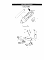
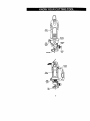
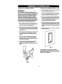
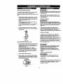
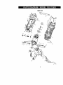
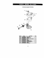
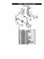
Owner's Manual
CRAFTSMAN+
ALL-IN-ONE
CUTTING TOOL
Model No.
183.172530
Important
Safety
Notice
IA WARNING
I
Always have one hand firmly
placed on the tool body
while operating_ Never
operate the tool by holding
®
only the tool handle.
CAUTION:
Before using this Cutting
Tool, read this manual and
follow all its Safety
and Operating
Instructions.
Rules
• . Safety Instructions
• Accessories
•
•
•
•
Assembly
Operation
Maintenance
Parts List
• Espanol
Sears, Roebuck and Co., Hoffman Estates, IL 60179 USA
Part, No, 183172530001
Rev. 0 t2/25/02
SECTION
Warranty ........................................
Product Specifications ......................
Power Tool Safety ............................
Cuffing Too_Safety ...........................
Electrical Requirements & Safety ........
Accessories ....................................
PAGE
2
2
3
4
5
6
SECTION
Carton Contents ..............................
Know Your Cuffing Too/ ....................
Assembty & Operation ......................
Maintenance ...................................
Repair Parts ...................................
Parts & Service Availability ................
PAGE
6, 7
8
9 - 13
13
14 - 17
18
FULL ONE YEAR WARRANTY
If this Cuffing Tool fails due to a defect in material or workmanship within one year of date of
purchase, Sears will at its optionrepair or replace it free of charge.
Return this Cuffing Tool to a Sears Service Center for repair, or to place of purchase for
replacement.
This warran0/gives you specificlegal rights, and you may also have other rights which may vary
from state to state.
Sears, Roebuck and Co., Dept. 817 WA, Hoffman Estates, IL 60179
[A
WARNING
I
Some dust created by power sanding, sawing, grinding, drilling and other construction activities contains
chemicals known (to the State of California) to cause cancer, birth defects or other reproductive harm. Some
examples of these chemicals are:
Lead from lead-b;_ed paints
Crystalline silica from bricks, cement and other masonry products
•
Arsenic and chromium from chemically treated lumber
Your risk from these exposures verles_ depending on how often you do this type of work. To reduce your exposur_
to these chemicals, work In a wall ventilated area and work with approved safety equipment such as those dust
masks that are specially designed to filter out microscopic
p;lrticles.
Motor Rating ......................
Amperes ...........................
2 Speeds (no load) ..............
120V, 60Hz, AC
5.0 Amperes
20000 & 30000 RPM
Motor Horsepower ......
Weight .....................
3/4 HP (Maximum Developed)
1.7 kg
]Jh_ WARNING]
To avoid electrical hazards, fire hazards or damage to the cutting tool, use proper circuit protection.
This cutting tool is wired at the factory for 110-120 Volt operation. It must be connected to a 110-120 Volt 115
Ampere time delay fuse or circuit breaker. To avoid shock or fire, replace power cord immediately if it is worn, cut
or damaged in any way.
Before using your cutting tool, it is critical that you read and understand these safety rules. Failure to follow these
rules could result In serious InJery to you or damage to the cutting tool.
IA
WARNING]
Before using your cutting tool, it is critical that you read and understand these safety rules.
Failure to follow these rules could result in serious injury to you or damage to the cutting tool,
Good safety practices are a combination of common
sense, staying alert and understanding how to use your
power tool. To avoid mistakes that could cause serious
injury, do not plug in your cutting tool until you have read
and understood the following safety rules:
15. REMOVE ADJUSTING KEYS ANDWRENCHES.
Form the habit of checking tOsee that keys and
adjusting wrenches are removed from the tool before
taming =ON".
1.
16. NEVER LEAVE TOOL RUNNING UNAI-rENDED.
TURN THE POWER "OFF". Do not leave the tool
before it comes to a complete stop.
READ and become familiar with this entire Owner's
Manual. LEARN the tool's applications, limitations and
possible hazards.
17. NEVER STAND ON TOOL. Serious injury could occur
if the tool is tipped or if the cutting tool is
unintentionally contacted.
2.I& WARNINGI
Look for this symbol that identifies important safety
precautions, it means CAUTIONI BECOME ALERTI
YOUR SAFETY IS INVOLVED!
3.
KEEP GUARDS IN PLACE and in working order.
4.
DO NOT USE IN A DANGEROUS ENVIRONMENT
such as damp or wet locations or exposure to rain.
Keep work area well lighted.
5,
DO NOT use power tools in the presence of
flammable liquidsor gases.
6.
KEEP WORK AREA CLEAN. Cluttered areas and
workbenches invite accidents.
7.
KEEP CHILDREN AWAY. Ati visitors should be kept
at a safe distance from the work area.
8.
DO NOT FORCE THE TOOL It will do the job better
and safer at the rate for which it was designed,
9.
USE THE RIGHT TOOL Do not foree the tool or
attachment to do a job for which it is not designed.
'f8. DO NOT OVER REACH. Keep proper footing and
balance at aft times.
t9. MAINTAIN TOOLS WITH CARE. Keep toots sharp
and olean for most efficient and safest performance.
Follow instructions for lubricating and changing
accessories.
20, CHECK FOR DAMAGED PARTS. Before further use
of the tool, a guard or other part that is damaged
should be carefully checked to ensure it will operate
properly and perform its intended function. Check for
alignment of moving parts, binding of moving parts,
mounting and any other conditions that may effect its
safe operation. A guard or other part that is damaged
should be properly repaired or replaced.
21, MAKE WORKSHOP CHILD PROOF with padlocks,
master switches or by removing starter keys.
22. DO NOT operate the tool if you are under the
influence of any drugs, alcohol or medication that
could impair your ability to use the tool safely.
10. WEAR PROPER APPAREL DO NOT wear loose
clothing, gloves, neckties, rings, bracelets or other
ewelry that may get caught in moving parts. Non-slip
footwear s recommended. Wear protective hair
covering to contain long hair.
23. USE DUST COLLECTION SYSTEM wherever
possible. Dust generated fTom certain materials can
be hazardous to your health and in some cases, a fire
hazard. Always operate the power tool in a well
ventJlatad area with adequate dust removal.
11. WEAR A FACE MASK OR DUST MASK. Sawing,
cutting, drillingand sanding operations produce
hazardous dust.
24. ALWAYS WEAR EYE PROTECTION.
Any power tool
your eyes which could catJse
permanent eye damage.
can throw foreign objects into
ALWAYS wear safety goggles
(not glasses) that comply with
ANSI safety standard 7_87.1. Everyday gtasaes have
only impact resistant lenses. 111eyARE NOT safety
glasses. Safety goggles are available at Sears.
12. DISCONNECT TOOLS FROM THE POWER
SOURCE before sewicing and when changing
accessories such as blades, bits, cutters, etc,
13. REDUCE THE RISKOF UNINTENTIONAL
STARTING. Make sure the switch is in the "OFF"
position before plugging into the power source.
1A WARNING I
14. USE ONLY RECOMMENDED ACCESSORIES.
Consult the Owner's Manual for recommended
accessodss. The use of improper accessories may
cause injury to you or damage to the tool
GlaSses or goggles not In compliance with ANSI
Z87,1 could cause serious Injury when they break.
SAVE THESEINSTRUCTIONS
3
FOR REFERENCE
IA WARNING)
For your safety, do not plug in your cutting tool or try
to use any accessory until it is completely assembled
and installed according to these instructions, and
until you have read and understood this Owner's
Manual.
11. NEVER HOLD THE WORKPIECE IN ONE HAND
while operating the tool with the other hand.
Failure to follow these safety rules will result in risk of
serious Injury.
13. NEVER START THE TOOL WHEN THE BIT IS
TOUCHING THE WORKPIECE. The bit may catch
the workplace causing loss of control,
1.
2.
WEAR EYE PROTECTION. This high speed tool will
throw particles from the workpiese dudng operation.
Make sure safety glasses have side shields.
USE HEARING PROTECTION,
extended pedods of operation.
4.
NEVER USE DULL OR DAMAGED BITS, Damaged
bits can break without warning. Dull bits may overload
the motor, cut slewiy and are difficult to control. They
will also overheat and possibly break.
5.
ALWAYS MAKE SURE THE WORKPIECE IS FREE
OF NAILS AND OTHER FOREIGN OBJECTS. If the
bit stdkes a nail it will jump sideways and possibly
break.
t5. TURN OFF ALL CIRCUIT BREAKERS AND
REMOVE ALL FUSES in the work area when cutting
into walls or blind areas.
perticulady dunng
6.
DO NOT USE THIS TOOL FOR DRILUNG
It is NOT intended to be used as a ddlL
7.
ALLOW CLEARANCE UNDER WORKPIECE for bit
to travel. Never place workplace on hard surfaces
such as concrete etc. The bit may jump or break when
contacting a surface other than the one being cut,
9.
t4. ALWAYS HOLD THE TOOL WITH I_VO HANDS
DURING START-UP AND OPERATION. When
starting, motor torque will cause the tool to twist.
USE FACE OR DUST MASK along with safety
goggles if cutting or muting operation is dusty, Make
sure work area is well ventilated,
3.
8.
12. NEVER PLACE HANDS IN THE PATH OF THE
cUTrER AND UNDER THE WORKPIECE.
16, ALWAYS HOLD THE TOOL BYTHE INSULATED
GRIPPING SURFACES ON THE BODY OF THE
TOOL where there is any possibilityof the cutting bit
contacting hidden electrical wires or the cord of the
tool. Contact with "live" wires will make exposed metal
parts of the tool "live" causing an electrical shock to
the operator.
17, WHEN CUTTING DRYWALL ELECTRICAL OUTLET
OPENINGS using the outlet as a guide, always cut in
a counter clockwise direction. The natural tendency of
the tool to pull to the left will cause a "hugging" action
toward the outlet box, resulting in a neatar cut.
HOLES.
18. NEVER LAY THE TOOL DOWN UNTIL THE
CUTTING BIT COMES TO A COMPLETE STOP. A
spinning bit can come in contact with the surface and
pull it out of your control,
19, NEVER TOUCH THE CUTRNG BIT IMMEDIATELY
AFTER USE. The bit will be too hat to be handled with
ALWAYS SET THE DEPTH GUIDE TO THE
APPROPRIATE DEPTH. Use tool with the depth
guide fiat against the work surface for better control of
the tool.
bars hands and will bum your fingers.
20, ALWAYS RE-TIGHTEN
COLLET AND ALL
ADJUSTMENTS before starting the too/after a cutting
bit or accessory has been changed. Loose bits and
adjustments can cause unexpected shifting of the tool
resulting in loss of control and injury from the bit or
cutting tool being thrown.
NEVER USE THE TOOL WITHOUT THE SOLE
pLATE, PRECISION HANDLE OR ROUTER BASE
attached and appropriately adjusted.
10. ALWAYS CLAMP WORKPIECE TO HOLD IT
S1T=ADY WHEN CUTnNG, This will free both hands
for operating the tool.
SAVE THESE INSTRUCTIONS
4
FOR REFERENCE
Ie]|J =_lil= II_l-_|l W±lil[o]_
This cutting tool is double insulated to protect you from
electrical shock.
IA WAJ NING
I
Double insulated tools are equipped with a polarized
plug (one blade is wider than the other). This plug will
fit into a polarized outlet only one way. ffthe plug
does not fit fully into the outlet, reverse the plug. If it
still does not fit, contact a qualified eis_dcisn to
install a polarized outlet. [3o not alter the plug in any
way. Double insulation eliminates the need for the three
wire grounded power cord and grounded power supply
system.
Avoid body contact with grounded surfaces such as
pipes, radiators, ranges and refrigerators. There is an
increased risk of electric shock if your body is grounded.
Do not expose power tools to rain or wet conditions.
Water entedng a power tool will increase the risk of
electric shock.
Do not abuse the cord. Never use the cord to carry
the tool or pull the plug from the outleL Keep cord
away from heat, off, sharp edges and moving parts.
Replace damaged cords Immediately. Damaged cords
increase the dsk of electdc shock.
When operating a power tool outdoors, usa an
outdoor extension cord marked "W-A" or "W". These
cords are rated for outdoor use and reduce the risk of
electric shock.
IJ_ WARNING I
Always makesure the receptacle is polarized. If you
are not sure, have a qualified electrician check the
receptacle.
Make sure your extension cord is in good condition.
When using an extension cord, be sure to use one heavy
enough to can/the current the tool will draw. An
undersized cord will cause a drop in line voltage resulting
in lose of power and overheating. The table below shows
the correct size to use according to cord length and
nameplate ampere rating. If in doubt, use the next
heavier gauge. The smaller the gauge number the
heavier the cord.
Be sure your extension cord is properly wired and in
good condition. Always replace a damaged extension
cord or have it repaired by a qualified electrician before
using it. Protect your extension cord from sharp ct_jects,
excessive heat and damp or wet areas.
Use a separate electrical circuit for your power tools.
This circuit must not be less than 14 gauge wire and
should be protected with either a 15 Ampere time delay
fuse or circuit breaker. Before connecting the power tool
to the power source, make sure the switch is in the OFF
position and the power source is the same as indicated
on the nameplate. Running at lower voltage will damage
the motor.
IA WARNING
I
Repair or replace
immediately,
damaged or worn extension cords
Select the appropriate extension cord gauge and length
using the chart below.
MINIMUM GAUGE (AWG) EXTENSIONCORDS
(120 Volt use only)
Ampere Rafing
Not
MoreThan
MoreThan
0
6
6
10
10
t2
12
16
Total length in feet
25'
t8
t8
50' I 100'
16
16
16 ] 14
150'
14
12
t6
t4
16 I NotApplicable
14
12
12
IA WARNINGI
Keep the extension cord clear of the working area.
Peeltlon the cord so it will not got caught on the
workpiece, tools or any other obstructions while you
are working with the power tool.
;f-'1£.4I[o]_EaZo]_ III _ _| I_
AVAILABLE
ACCESSORIES
UNPACKING
IA WARNINGI
[A
Use only accessories recommended for this cutting
tool. Follow instructions that accompany accessories.
Use of improper accessories may cause injury to the
operator or damage to the cutting tool.
ff any pert is missing or dameged, do not plug the
cutting tool into the power source until the missing
or damaged part is replaced end assembly is
complete.
Visit your Sears Hardware Department or see the Sears
Power andHand Tool Catalog for an assortment of
accessories recommended for use with this cutting tool:
Carefully unpack the cutting tool and all its components,
Compare against the "Cutting Tool Components" chart
below.
NOTE: See Page 7 for illustration of components,
Flex Drive
(_,
Rip Guide
Router
Circle Cutter
I/_" Curt'rag Bits
_ls" Hobby Rotary Tool Accessories
_- Cutters
;" Polishers
_. Sanders
>, Gdnders
Most ¼" Shank Router Bits
AND CHECKING CARTON CONTENTS
WARNING
WARNING
I
I
To avoid fire or toxic reaction, never use gasoline,
naphtha, acetone, lacquer thinner or similar highly
volatile solvents to clean the cutting tool.
cuTrlNG
KEY r
A
B
C
D
IA WARNINGI
Use only accessories designed for this cutting tool to
avoid severe injury or tool damage.
E
F
G
H
I
J
Do not use any accessory unless you have
completely read the instructions or Owner's Manual
for that accessory.
TOOL COMPONENTS
DESCRIP'flON
I QTY
Cutting Tool Box
Cutting Tool
Collet Wrench
Collet Wrench Holder
Owner's Manual
Accessory Box
Precision Handle with Sole Plate
Freehand Sole Plate Attachment
1/8" Collet Sleeve
1/4" Collet Sleeve
Lateral Styte Drywall Cutter
Wood / PlasUc / Fiberglass Cutter
1
1
1
1
1
1
1
1
1
1
NOTE: The two most commonly used cutters are
included with this tool (items I & J). It is Important
that you use the co_
cutter to ensure the most
efficient cutting action.
6
•
Use cutter =1"with the finer spiral for cutting
drywall
•
Use the general purpose cutter "J" wIth the
coarser spiral for cutting materials such as wood,
plastic and fiberglass.
Cutting Tool Box
Accessory
Box
I
J
7
Rate
IA
WARNING]
Remove the plug from the power source before
assembly, changing accessories or cutters and
making adjustments. This safety action will help
prevent accidental starting of the tool which could
result in serious injury.
INSTALLING
4.
CUTRNG
BITS - Cont'd
Insed new cutting bit (4) into the collet.
IA
WARNING
I
Insert the bit all the way into the cohet and then
pull it back between t/t0" and l/e", This creates an
air space between the motor shaft end the hit to
help prevent overheating the bit.
OH I OFF & SPEED CONTROL SWITCHES
This cutting tool is equipped with a sliding ON / OFF
switch (1) located on the side of the tool and a speed
control switch (2) located on top of the tool (see Fig. 1).
Before tightening the collet on the bit, make sure
the flutes (spiral portion) of the bit ere completely
visible outside the catfat. Clamping the coltst on
the bit flutes will result in broken bits and possible _
injury.
5,
When hit is propedy placed in the collet, depress the
shaft locking button and turn the collet nut clockwise
by hand as far as possible,
6.
Securely tighten collet nut using the wrench.
Fig. 1
1.
TO turn the toot ON, slide the switch (1) up.
2.
To turn the tool OFF, slide the switch down,
4
3. To set speedto highspeed,slidespeedcontrolswitch
(2) awayfromthe ON / OFF switch.
4.
INSTALLING
iA
WARNING
CUTtiNG
I
To insert a cuffing bit, use the collet wrench which is.in the
wrench holder attached to the power cord.
Deprese the shaft locking bufton (1} and mtste the
collet lock nut (2) clockwise with the other hand until
the locking button drops into place, preventing the
shaft from turning (see Fig, 2).
2.
While continuing to hold the shaft locking button IN,
use the coflet wrench (3) to rum the collet nut counter
clockwise. Loosen the collet nut two or three turns.
3.
Remove bit if one is already installed in the tool.
2
Fig. 2
BITS
Cutting bit and router bit cutting surfaces are
extremely sharp. Handle with caution.
1.
3
To set the speed control switch to low speed, slide the
speed control switch (2) toward the ON / OFF switch.
WORK LIGHTS
The motor unit has two buitt-in work lights (5) (see Fig, 2).
These work lights automatically light up when the motor
switch is famed ON. Patterns or drawings in the
immediate vicinity of the bit will be illuminated for better
visibility and improved cutting accuracy.
SELECT APPROPRIATE
MOTOR SPEED
Selecting the appropriate motor speed will ensure
smoother, more efficient cutting action. Choose LOW
speed for grinding, cuffing plastics, polishing and when
using wire or bristle brushes. Cheese HIGH speed when
cutting wood. using cut-off wheels and to reduce "shatter"
that may develop when cutting some materials at LOW
speed.
CHANGING
COLLET
INSERT
INSTALLING
Thecutting
1.
Slide freehand sole plate mounting bracket (1) onto
the bottom of motor housing (2) until the slot in the
bracket (3) lines up with the shaft locking button (4) in
the motor housing.
NOTE: The mounting bracket must be pushed onto
the motor housing as far as it will go.
2.
Lock the sole plate to the motor housing by snapping
the quick locking lever (5) firmly against the motor
housing.
bits for this tool are locked into place with a
collar nut (1) and coJlet (see Fig. 3). The tool is assembled
at the factory with NO coilet installed. Both the l/a" and ¼"
coilets can be found in the carrying case front lid storage
compartment. The 1/8" toilet (2) is used for holding hobby
tool accessory bits. The ¼" coflet (3) is supplied for
holding SMALL router bits with a %" shank.
FREEHAND
SOLE PLATE - €ont'd
2
4
Fig. 3
3
To change from one cotlet size to the other:.
1.
Remove bit from the tool.
2.
Continue turning the collet nut counter clockwise until
it can be removed from the motor shaft (4).
3.
Pull the co,el out of the motor shaft and replace it with
the other one.
NOTE: Each collet is the same on both ends, so either
end can be inserted into the motor shaft,
5
Fig. 4
ADJUSTING
1.
4.
Re-install the collet nut and slightly tighten it by hand.
5.
Install the new bit as outlined in INSTALLING
CUTTING BITS on Page 9.
NOTE: Tightaning the oollet nut without a bit in the sallet
will cause the collet hole to become smaller and make
installing bits difficult. When stodng the toot with no bit
installed, leave collet nut loose.
j _'4::1:1:r_,l_A0]l,-,]la]iP_s-_J
_,__-_
._
INSTALLING
FREEHAND SOLE PLATE
The freehand sole plate is designed for basic freehand
cuffing with the cuffing bit. It is ideally suited for cuffing
electrical outlet holes in dPJwall.
IA
FREEHAND SOLE PLATE
Adjust freehand sole plate depth by loosening the
depth gauge locking knob (6) and rotating the
adjusting knob (7) to move the sole plate in or out as
required (see Rg. 5).
NOTE: Set the depth gauge so the cutting bit
protrudes beyond the sole plate 1/0" more than the
thickness of the matadal being cut. For example, if
you are cutting s/6"drywall, the bit should protrude ¾"
beyond the sole plate.
2.
Securely tighten depth gauge knob.
3.
Before starting to cut you should re-check bit depth.
Make sure sole plate is at dght angles to the bit and
securely tightened. Re-check the collar to make sure
the bit is sacureb/fastened.
WARNING I
Do NOT use the freehand sole plate with router bits.
Limited control with this accmmory could cause you
to lOOSecontrol and Increasethe chance of serious
Injury,
Fig. 5
lO
PRACTICE CUTS USING FREEHAND SOLE PLATE
,_k WARNING
J
Have you read "pOWER TOOL SAFETY",
"CUI-rING TOOL SAFETY" and "ELECTRICAL
SAFETY" on pages 3, 4 and 5 of this Manual? If
not, please do it now before you operate this
cutting tool. Your safety depends on ttl
Every time you use the cutting tool you should
verify the following:
1. Cutting tool cord is not damaged.
2. Bit is correct type for the material being cut.
3. Bit is sharp, in good condition, properly
installed and securely tightened.
4. Safety glasses and dust mask are being worn.
6.
Set the speed control switch to the appropriate speed.
7.
Turn the switch ON.
8,
When the motor is up to full speed, slowly tip the tool
to an upright position, le_ng the bit cut into the
work.piece (see Fig. 7). Once the tool has roached the
updght position and the bit has cut through the
workpiece, slowly move the tod in a clockwise
direction using slow steady pressure to make the cut.
NOTE: Except for cutting around outlet boxes in
drywall, always cut in a clockwise direction.
9.
When cut is complete, turn the tool OFF, wait until it
comes to a complete stop and remove it from the
workpiece,
Failure to adhere to these safety rules can greatly
increaseyour chances of injury.
PRACTICE CUTS USING FREEHAND
SOLE PLATE
Before attempting to work on an actual project, take the
time to make a few precise cuts with your cutting tool.
Use some scraps of moledal that are the same material as
used in your actual project.
1.
2.
Draw a pattern similar to your first project on a scrap
piece of material.
Fig. 7
Install freehand sole plate as shown in Fig. 4.
IA O ( ER]
Do not attempt cutting around outlet boxes in drywall
until:
1. All electricity in the vicinity of electric wires has
been dtaconns_ted by either turning the breaker
OFF or removing the fuses.
3. Installcuttingbit in the collolas shownin Fig.2.
4.
Adjust depth of freehand sole plate as shown in Rg. 5.
5,
Rest the edge of the sole plate on the workpiece with
the bit at an angle of about 45 ° (see Rg. 6),
NOTE: DO NOT let the bit contact the workplece until
switch is turned ON and the tool is up to full speed.
2.
JA WARNING
I
You have read the instructions
on the following
page entitled "CUTTING OUTLET OPENINGS IN
DRYWALL".
cUTrlNG
Before turning the tool switch ON, make sure you
hold the tool firmly with both hands. Starting
torque will cause the tool to twtaL
TIPS
The rotating cutting action of the bit will cause a slight pull
to the left when cutting. Natural variations in the structure
of wood will cause the bit to "wander'. This tendency will
be magnified when applying too much pressure to the bit,
_ower cutting givoa you better control. Excessive
pressure or fast cuffing will increase bit temperature and
shorten _ life ofthe bit.
When cutting a hole in e vertical surface, avoid ending the
cut at the bottom Of the hole. Always start and end the cut
at the "top" so the cut.out part will not drop onto the
rotating bit. Always turn the tool OFF before removing it
from the workpiece.
Fig. 6
11
CUTTING OUTLET OPENINGS
IN DRYWALL
CUTI'ING OUTLET OPENINGS IN DRYWALL - cont'd
IAOANGER
I
Do not attempt to use this tool to make cut-outs
around any fixture or opening which has live electrical
wires or on any wall which may have electrical wiring
behind iL If a live wire is contacted, the bit could
conduct the electric current to the tool, creating an
electrocution hazard for the operator. Turn OFF
breakers or remove fuses to disconnect the electric
circuit in the area of work. Always hold the tool by its
insulated housing when working in areas where there
is a possibility of contacting electric wires. Always
wear eye protection when operating this tool.
1.
Before installing drywall, push the electdcal wires to
the back of the box as far as possible so they will not
be cut by the bit when cutting the opening.
2.
Before fastening the dr/wall sheet over the electrical
box, mark the sheet as close as possible to the center
of the box opening. Mark should be on the side of the
drywall facing you,
3.
4.
5.
6.
Move the bit slowly to the right until you feel and hea
the bit contacting the inside of the box.
7.
Put] the bit out far enough to slip it over the edge of
the box. Once the bit is outside the box. push it back
to full depth beside the out,de edge of the box.
8.
Move the toct upward while applying slight pressure
toward the center of the box. When you feel the bit
roach the top dght hand comer of the box, move the
tool to the left while applying slight pressure
downward toward the center of the box.
9.
Continue moving the tool around the box in a counter
clock'w_se direction while maintaining slight pressure
toward the center of the box. When the box cut-out is
complete. Turn the tool OFF and remove it from the
cut-out,
10. Completed electrical box cut-out will be accurately an_
neatly cut (see Fig. 9).
When fastening the drywall in place, do not place nails
or screws closer than 12" from the box. This will
prevent the drywall from becoming deformed under
pressure.
i
I
Insert cutting bit and install freehand sole plate as
outlined on Pages 9 & 10 of this Owner's Manual.
Adjust depth of cut so the bit will protrude l/s" beyond
the thickness of the drywall.
I
I
\
Hold the tool firmly with both hands and tum it ON.
Runge the bit through the drywalt at the mark
indicating the center of the box. See Fig. 8 for cutting
pattem.
Fig. 9
NOTE: Always move the cutting bit in a counter
dockwlee direction around the oullet box. The natural
tendency of the cuffing bit _ move to the left will make it
easier to cut close to the box.
Fig. 8
12
i-|:[l_l._][a] _1 -"r:1_isis
INSTALLING
vtF-'II _/III LIF_,I
_[_
I
PRECISION HANDLE
I,_. DANGER
For your own safety, turn the switch OFF and remove
the plug from the power source before maintaining
your cutting tool.
The precision handle is designed for use when precision
control over the tool movement is desired. The
comfodabie handle can be used with either the dght or left
hand.
1.
2.
When servicing, use only identical Craftsman ports.
Use of any other part may create a hazard or cause
product damage,
Slide precision handle mounting bracket (1) onto the
bottom of motor housing (2) unffi the slot under the
handle (3) lines up with the shaft tocking button (4) in
the motor housing (son Fig. 10).
NOTES:
EXTERNAL CLEANING
IA W NINGJ
a) The mounting bracket must be pushed onto the
motor housing as far as it will go.
b) The shaft locking button (5) can now be activated
by your thumb while holding on to the precision
handle
DO NOT use solvents when cleaning plastic parts.
Most plastics are susceptible to damage from various
types of commercial solvents and may be damaged by
their use. Use clean cloth to remove dirt, dust, oil,
grease, atc.
Lock the predsion handle to the motor housing by
snapping the quick locking lever (6) firmly against the
motor housing.
Do not at any time allow brake fluids, gasoline,
petroleum-based products, penetrating oils, etc. to
come in contact with plastic parts. They contain
chemicals that cen damage, weaken or destroy plastic
INTERNAL CLEANING
It has bonn found that electdc tools are subjected to
accelerated wear and possible premature failure when
they are used on fiberglass boats and sports cars,
wallboard, spackling compounds or plaster. The chips and
gdndings from these materials are highly abrasive to
electric tool parts such as beadngs, brushes, commutaton_,
etc. Dudng any use on these materials it is extremely
important that the tool is cleaned frequently by blowing out
with a compressed air jet.
Fig. 10
ADJUSTING
1.
FREEHAND SOLE PLATE
Adjust precision handle sole plate depth by loosening
the depth gauge locking knob (7) and rotating the
adjusting knob (8) to move the sole plate (9) in or out
as required (see Fig. 11).
NOTE: Set the depth gauge so the cutting bit
protrudes beyond the sole plate _/a" more than the
thickness of the material being cuL For example if
you are cutting 3/4"pine, the bit should pm_Jde fiB"
beyond the sole plate.
I_,
DANGER
]
It Is critical that you wear safety goggles or safety
glasses with side shields and a dust mask while
blowing dust out of the cutting tool with a
compressed air jet. Failure to take these safety
precautions could result in permanent eye or lung
damage.
POWER CORD MAINTENANCE
2.
Securely tighten depth gauge knob.
3.
Before starting to cut you should recheck bit depth,
make sure sole plate is at right angles to the bit and
securely tightened. Re-check the coliet to make sure
the bit is oncumly fastened.
I_h, WARNINGJ
To avoid shock or fire hazard, replace the cord
immediately if it is worn or damaged in any way.
LUBRICATION
A_Iof the bearings in this cuffing tool are lubdcated with a
sufficient amount of high grade lubricant for the life of the
unit under normal conditions. Therefore, no further
lubrication is required.
Fig. 11
13
Main Unit
14
IA w ,J.6 I
When servicing use only CRAFTSMAN replacement
damage to your Cutting Tool.
parts. Use of any other parts may create a HAZARD or cause
Any attempt to repair or replace electrical parts on this Cutting Tool may create a hazard unless repair is
performed by s qualified technician, Repair service is available by contacting your nearest Sears Service Center.
Always
order by PART NUMBER,
not by key number.
Main Unit
Key #
Part #
1
01AR-O00032-0O
2
! 01AR.-000035_0
3
01AT-000014-A0
5
01AT-O00031-00
10
02AE-O00060-00
11
02AE-O00061-00
12
02AK_00022-00
Part Name
Beadng Sleeve
Switch presser
Bushing tube
Bushing tube
Front beadng
Rear beadng
Rivet
13
14
15
17
18
02AH-000088-00
02AH-000089-00
02AH-000112-00
02AS-000199-A0
02AS-000201-A0
Brush spdng
Spindle spring
Hanger
Case screw
Screw
22
23
02AW-000055--00
03AA-000279_0
Retaining ring
Transformer
24
25
28
29
30
31
34
35
36
37
38
39
40
41
42
03AC-000011 -F0
03AC-000043-00
03AD-OO0009-A0
03AD-OOO040-0O
03AD-000074-00
03AD-000075-00
03AM_00104_0
03AM-000105-00
03AP-000073-00
03AP_00076-00
03AR-000013-AO
03AR-000015-D0
03AR-000109-A0
03AS-000135-00
03AS-000140_00
Capacity
Capacity
Diode
Diac
LED
Triac
Stator
Rotor
PCS
PCB
Resistor
Resistor
Resistor
Micro switch
Switch
Qty
1
Key #
44
Part #
03AT-O00033-00
Part Name
Terminal block
Qty
1
1
2
2
1
1
4
2
1
1
48
49
50
53
55
56
59
62
82
03AT-000040-O0
03AT-000046_0
03AW_00131-00
03AY-000020-00
03AY.-000073-00
03AY...(X)0074-00
04AP-000068-00
2203-MA0003-00
2203-MA0004-00
Terminal (female)
Carbon brush
Power cord
Wire
Wire
Wire
Fibra
1/4" collet
1/8" toilet
2
2
1
1
2
2
1
1
1
8
3
1
63
87
70
2203-MA0007-00
2207-MA0003-00
2213-MA0002-O0
Lock plate
Spindle lock
Conductor
1
1
2
1
1
1
4
1
2
71
72
73
74
76
2213-MA0005-O0
2213-MA0006-00
2213-SAM001-00
2213-MA0011-00
2213-MA0012-00
2213-MA0014-00
Chuck cap
Spanner
Sms_ assembly
Metal conducter
Brush case
Wire cover
1
1
2
2
2
1
1
1
1
77
79
81
2213-MA0015.O0
2203-PA0008-00
2213-PA0022-00
Stop plate
Spanner belt
Bottom cabinet
1
1
1
1
1
1
1
3
1
1
82
83
84
85
87
91
92
2213-pA0023-00
2213-PA0024-00
2213-PA0025-00
2213-pA0026-O0
2213-PAD028-00
9866-PA0004-00
9920-PA0011-00
Top cabinet
Switch cover
Lock button
Cover
2P-Switch
Press plate
Cord Sleeve
1
1
1
t
1
1
1
15
Freehand
Soleplate
Assembly
212
2O2
2°,
208
215
214
203
216
\
213
Key#
201
202
203
208
2tl
212
213
214
215
216
part#
02AF-000041-10
02AF-000076-00
02AS-000287-00
2213-MA0010-00
22t3-PA0010-00
2213-PA0011-00
2213-PA0012-00
2213-PA0013-00
2213-PA0014-00
2213-PA0015-00
Part Name
Fodngshaft
Releaselock pin
Screw
Freecutmetalround guide
Lock
F_base
plasticguidebase
Adjus_nentGear 151"
Sleeve
Screwlock F
16
oty
1
1
1
1
1
1
1
1
1
1
Handle
Assembly
,11301
321
Part#
02AF-000041-10
02AF-000076-00
02AH-000106-00
02AS-000148-00
02AS-000199-A0
02AS-000287-00
02AS-000288-00
02AW-000067-00
2213-MA(X)13-00
2213-PA0010-00
2213-PA0012-00
2213-PA0013-00
2213-PA0014-00
2213-P/_0015-00
2213-PA0016-00
2213-PA0017-00
2213-PA00t8-00
2213-PA0019-00
2213-PA00LT0-00
221_-PA0021-00
Part Name
Fixingshaft
Releaselock pin
Compressivespdng
Screw
Screw
Screw
Screw
Washer
S-roundguideholder
Lock
Ple._c guidebase
Ad.kastmeotGear 15"1"
Sleeve
Scow lock F
Anx righthandle
Ar_ left handle
Anx handlesoft_o (outskle)
Anx handleso_p (i_de)
Shaft F5-5
17
For repair of major brand appliancesin your own home...
no matter who made it, no matter who sold it!
1-800-4-MY-HOME
®
Any_me,
dayornight
(1-300-469-4663)
(U.SJ_andCanada)
WWW.sears.collt
wlNw,sears.cEi
For repair of curry-inproductslike vacuums, lawn equipment,
and electronics,call for the locationof your nearest
Sears Parts and Repair Center.
1-800-488-1222
Any_me,
dayorn_ht(U.SAonly)
www.sean;.com
For the replacement parts, accessoriesand owner's manuals
that you need to do-R-yourself,cull Sears PartsDirectSUl
1-800-366-PART
sa.rn.-11 p.m.CST,7daysaweek
(1-800-366-7278)
(U.S.A.only)
www.sears.com/par
ts direct
To purchaseor inquireabout a Sears Service Agreement
or Sears MaintenanceAgreement:
1-800-827-6655
(u.s._)
1-800-361-6665
7 a.m.- 5 p.m.CST,Mon.- SaL
9 a.m.- 8 p.m.EST,M- F, 4 p.m.Sat
Parapedrservido
derepa'ad_a
domicilio,
y parao=denar
piezas:
1.88B.SU.HOGAR
(Canada)
._uCanada
pourse_ceenfrarx;_s:
1-800-LE-FOYER
Mc
sM
(1-800-53.3-6937)
(1-888-784-6427)
www.seam.ca
@ RIg_mld Tmd_ll_
I _ Tmdlmwk I IM Sen_m I&lrk _ :Sunl, _
Ind C_
@_
Re_t_nCal l ltd Metca de FM_lk:a l m Ma_l de _a'._o
de Seltl, Roebu_ and Co.
=¢ Ma_
dl _
l Va Matq_ d6pol_e de Seam, Ro_
lmd Co.
18


![Hire And Sales Catalogue V4.40 [april2013].](http://vs1.manualzilla.com/store/data/005975062_1-8950e43f7cbe305f577dc550ee5fbd1b-150x150.png)