1
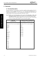
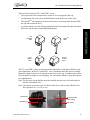
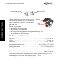
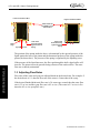
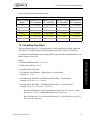
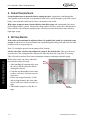
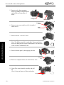
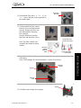
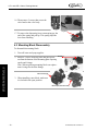
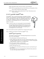
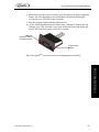
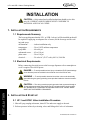
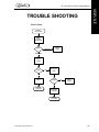
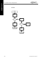
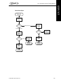
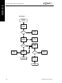
UF-1 AND UFB-1 VALVES
TRAINING MANUAL
CARBON DIOXIDE
WATER
SYRUP/CONCENTRATE
MECHANICAL
REFRIGERATION
CONTROLS & ELECTRICAL
Blank Page
UF-1 and UFB-1 Valves Training Manual
UF-1 and UFB-1 VALVES
TRAINING MANUAL
The products, technical information, and instructions contained in this manual are subject to
change without notice. These instructions are not intended to cover all details or variations of the
equipment, nor to provide for every possible contingency in the installation, operation or maintenance of this equipment. This manual assumes that the person(s) working on the equipment have
been trained and are skilled in working with electrical, plumbing, pneumatic, and mechanical
equipment. It is assumed that appropriate safety precautions are taken and that all local safety and
construction requirements are being meet, in addition to the information contained in this manual.
To inquire about current revisions of this and other documentation or for assistance with any Cornelius product contact:
IMI Cornelius Inc.
Internet:
www.cornelius.com
Email:
[email protected]
Trademarks and copyrights:
Aurora, Cornelius, Decade, Hydro Boost, Optifill, Sitco, Spirit, UF-1, Vanguard, Venture, and
Vista are registered trademarks of IMI Cornelius Inc.
This document contains proprietary information and it may not be
reproduced in any way without permission from Cornelius.
Printed in U.S.A.
Copyright © 1999-2005, All Rights Reserved, IMI Cornelius Inc.
© 1999-2005, IMI Cornelius, Inc.
- -3 -
UF-1 Valves Manual
NOTES:
_____________________________________________________________________________
_____________________________________________________________________________
_____________________________________________________________________________
_____________________________________________________________________________
_____________________________________________________________________________
_____________________________________________________________________________
_____________________________________________________________________________
_____________________________________________________________________________
_____________________________________________________________________________
_____________________________________________________________________________
_____________________________________________________________________________
_____________________________________________________________________________
_____________________________________________________________________________
_____________________________________________________________________________
_____________________________________________________________________________
_____________________________________________________________________________
_____________________________________________________________________________
_____________________________________________________________________________
_____________________________________________________________________________
_____________________________________________________________________________
_____________________________________________________________________________
_____________________________________________________________________________
_____________________________________________________________________________
TABLE OF CONTENTS
INTRODUCTION . . . . . . . . . . . . . . . . . . . . . . . . . . . . . . . . . . . . . . . . . . . . . . . . . . . . . . . . . . . . 1
Preview Questions . . . . . . . . . . . . . . . . . . . . . . . . . . . . . . . . . . . . . . . . . . . . . . . . . . . . . . . . . . 1
Key Things To Know / Do . . . . . . . . . . . . . . . . . . . . . . . . . . . . . . . . . . . . . . . . . . . . . . . . . . . 1
Overview . . . . . . . . . . . . . . . . . . . . . . . . . . . . . . . . . . . . . . . . . . . . . . . . . . . . . . . . . . . . . . . . . 2
Product Description . . . . . . . . . . . . . . . . . . . . . . . . . . . . . . . . . . . . . . . . . . . . . . . . . . . . . .2
Dimensions & Capacities . . . . . . . . . . . . . . . . . . . . . . . . . . . . . . . . . . . . . . . . . . . . . . . . . .4
SYSTEM DETAILS . . . . . . . . . . . . . . . . . . . . . . . . . . . . . . . . . . . . . . . . . . . . . . . . . . . . . . . . . . 5
Water . . . . . . . . . . . . . . . . . . . . . . . . . . . . . . . . . . . . . . . . . . . . . . . . . . . . . . . . . . . . . . . . . . . . 5
Water Quality . . . . . . . . . . . . . . . . . . . . . . . . . . . . . . . . . . . . . . . . . . . . . . . . . . . . . . . . . . .5
Water Flow . . . . . . . . . . . . . . . . . . . . . . . . . . . . . . . . . . . . . . . . . . . . . . . . . . . . . . . . . . . . .5
Adjusting Flow Rates . . . . . . . . . . . . . . . . . . . . . . . . . . . . . . . . . . . . . . . . . . . . . . . . . . . . .6
Calculating Flow Rates . . . . . . . . . . . . . . . . . . . . . . . . . . . . . . . . . . . . . . . . . . . . . . . . . . . .7
Syrup/Concentrate . . . . . . . . . . . . . . . . . . . . . . . . . . . . . . . . . . . . . . . . . . . . . . . . . . . . . . . . . . 8
Setting Ratios . . . . . . . . . . . . . . . . . . . . . . . . . . . . . . . . . . . . . . . . . . . . . . . . . . . . . . . . . . . . . . 8
Mechanical. . . . . . . . . . . . . . . . . . . . . . . . . . . . . . . . . . . . . . . . . . . . . . . . . . . . . . . . . . . . . . . . 9
UF-1 Valve Disassembly . . . . . . . . . . . . . . . . . . . . . . . . . . . . . . . . . . . . . . . . . . . . . . . . . .9
Mounting Block Disassembly . . . . . . . . . . . . . . . . . . . . . . . . . . . . . . . . . . . . . . . . . . . . . .12
Controls and Electrical. . . . . . . . . . . . . . . . . . . . . . . . . . . . . . . . . . . . . . . . . . . . . . . . . . . . . . 13
UF-1 Portion Control Valve . . . . . . . . . . . . . . . . . . . . . . . . . . . . . . . . . . . . . . . . . . . . . . .13
Portion Control Valve Programming. . . . . . . . . . . . . . . . . . . . . . . . . . . . . . . . . . . . . 13
UF-1 OptifillTM Valve . . . . . . . . . . . . . . . . . . . . . . . . . . . . . . . . . . . . . . . . . . . . . . . . . . .14
OptifillTM Valve Programming . . . . . . . . . . . . . . . . . . . . . . . . . . . . . . . . . . . . . . . . . 14
INSTALLATION. . . . . . . . . . . . . . . . . . . . . . . . . . . . . . . . . . . . . . . . . . . . . . . . . . . . . . . . . . . . 16
Installation Requirements . . . . . . . . . . . . . . . . . . . . . . . . . . . . . . . . . . . . . . . . . . . . . . . . . . . 16
Requirements Summary . . . . . . . . . . . . . . . . . . . . . . . . . . . . . . . . . . . . . . . . . . . . . . . . . .16
Electrical Requirements . . . . . . . . . . . . . . . . . . . . . . . . . . . . . . . . . . . . . . . . . . . . . . . . . .16
Installation & Start-up . . . . . . . . . . . . . . . . . . . . . . . . . . . . . . . . . . . . . . . . . . . . . . . . . . . . . . 16
UF-1 Valve Installation Procedure . . . . . . . . . . . . . . . . . . . . . . . . . . . . . . . . . . . . . . . . . .16
INSTALLATION CHECKLIST . . . . . . . . . . . . . . . . . . . . . . . . . . . . . . . . . . . . . . . . . . . . . . 17
Retrofitting. . . . . . . . . . . . . . . . . . . . . . . . . . . . . . . . . . . . . . . . . . . . . . . . . . . . . . . . . . . . . . . 17
Mounting Block Removal . . . . . . . . . . . . . . . . . . . . . . . . . . . . . . . . . . . . . . . . . . . . . . . . .17
SERVICE . . . . . . . . . . . . . . . . . . . . . . . . . . . . . . . . . . . . . . . . . . . . . . . . . . . . . . . . . . . . . . . . . . 18
Preventative Maintenance . . . . . . . . . . . . . . . . . . . . . . . . . . . . . . . . . . . . . . . . . . . . . . . . . . . 18
Preventative Maintenance Procedures . . . . . . . . . . . . . . . . . . . . . . . . . . . . . . . . . . . . . . .18
Cleaning Valve . . . . . . . . . . . . . . . . . . . . . . . . . . . . . . . . . . . . . . . . . . . . . . . . . . . . . . . . .18
TROUBLE SHOOTING . . . . . . . . . . . . . . . . . . . . . . . . . . . . . . . . . . . . . . . . . . . . . . . . . . . . . . 19
© 1999-2005, IMI Cornelius, Inc.
- -1 -
TABLE OF CONTENTS
UF-1 and UFB-1 Valves Training Manual
TABLE OF CONTENTS
UF-1 and UFB-1 Valves Training Manual
ATTACHMENTS . . . . . . . . . . . . . . . . . . . . . . . . . . . . . . . . . . . . . . . . . . . . . . . . . . . . . . . . . . . 23
REVIEW. . . . . . . . . . . . . . . . . . . . . . . . . . . . . . . . . . . . . . . . . . . . . . . . . . . . . . . . . . . . . . . . . . . 24
-0-
© 1999-2005, IMI Cornelius Inc.
UF-1 and UFB-1 Valves Training Manual
INTRODUCTION
1. PREVIEW QUESTIONS
Check your current knowledge by taking a few minutes to answer the following questions:
1. What are the flow capacities of a UF-1 valve? _____________________________________
2. What are the flow capacities of a UFB-1 valve? ____________________________________
__________________________________________________________________________
3. Which syrup has the greatest pressure drop, diet or sugar?____________________________
__________________________________________________________________________
4. How do juice valves differ from carbonated beverage valves? _________________________
__________________________________________________________________________
5. Can you program “top-off” on a portion control valve? ______________________________
__________________________________________________________________________
6. What components must be replaced when retrofitting SF-1 to UF-1 valves? ______________
__________________________________________________________________________
2. KEY THINGS TO KNOW / DO
• For quality drinks — keep the nozzles and the water/syrup system clean; and have the correct
ratio, temperature, and carbonation!
• Set the water/syrup ratio accurately — and leave it alone!
• To set the ratio accurately, set the water flow first, then the syrup!
• Be sure to cool below 40°F the syrup and water before setting the ratio.
© 1999-2005, IMI Cornelius, Inc.
-1-
INTRODUCTION
__________________________________________________________________________
UF-1 and UFB-1 Valves Training Manual
3. OVERVIEW
3.1 Product Description
The UF-1 and UFB-1 valve provides accurate flow capability and dependability. The UF-1
and UFB-1 valves are capable of flow rates of 1 ½ to 3 ounces per second (high flow), 2 to
4 ounces per second (UFB-1), or 3 to 4 ½ ounces per second (ultra flow). The valve flow
control modules are the only parts that differ in the three versions.
INTRODUCTION
Note: The flow rate is also dependent on the capacity of the dispensing, cooling, and
carbonation systems. An ultra flow capacity valve will not make up for a slow
system flow rate or inadequate supplies of cooled water and syrup. The following
is a list of Cornelius units and the valve flow rates they support:
Fast Flow
1.5 to 3.0 oz./sec.
Vanguard
Value Line 2323 (10 circuit cold plate)
Venture
Vantage
1522
1722
2224
2230-100
DB 90
DB 150
DB 200
DB 250
DB 275
TJ 45
TJ 90
TJ 150
TJ 200
TJ 250
TJ 300
TJ 400
-2-
Fast Flow, UFB-1, or Ultra Flow
2 to 4 oz./sec. or 3.0 to 4.5 oz./sec.
Vanguard 245
Premium 2323 (12 circuit cold plate)
2230
3030
ED 150
ED 200
ED 250
ED 300
DF 150
DF 200
DF 250
© 1999-2005, IMI Cornelius Inc.
UF-1 and UFB-1 Valves Training Manual
There are four varieties of UF-1 and UFB-1 valves:
• The cup activated valve dispenses by means of a lever engaged by the cup.
• A push button valve has a press and hold button on the front cover of the valve.
•
•
The OptifillTM valve dispenses with an activation lever but stops after the liquid fills
the cup and touches the lever
A portion control valve has four programmable drink size buttons that provide timed
deliveries, top off, and a manual dispensing button.
Push
Button
Valve
INTRODUCTION
Cup
Activated
Valve
OptifillTM
Valve
Portion
Control
Valve
The UF-1 and UFB-1 valves are the same as described above with minor differences for
juice applications. In the UF-1 and UFB-1 valve concentrate enters the nozzle assembly
higher providing a better mix of concentrate and water in the cup. In addition, the orifices
for concentrate are larger to avoid clogging. The concentrate diffuser is gray allowing for
easy identification.
Note: The beverage (syrup) diffuser must be installed in order to use a diversion tube to
ratio the concentrate valve.
Note: Concentrate valves have only one hole in their sleeve and are only offered in fast
flow capacities of 1.5 to 3.0 oz./sec.
Syrup outlet
Black diffuser
© 1999-2005, IMI Cornelius, Inc.
Concentrate outlet
(better mixing)
Gray diffuser
-3-
UF-1 and UFB-1 Valves Training Manual
Concentrate valve sleeve
has only one hole
INTRODUCTION
A side water lever kit can be added to a valve
allowing for dispensing of water without syrup or
concentrate. The side water lever can be added to
either a carbonated drink valve or a noncarbonated drink valve.
Syrup valve sleeve
has six holes
Mounting
screw
Water
lever
Post-mix valves control:
• the ON–OFF of syrup and water,
• the flow rates of syrup and water,
• the mixing of the two ingredients as they pour into the cup, and
• in some instances - dispensed portion.
3.2 Dimensions & Capacities
Fast Flow - - - - - - - - - - - - - - - - - - - - - - - - - - - - - - 1 ½ to 3 oz./sec.
UFB-1 - - - - - - - - - - - - - - - - - - - - - - - - - - - - - - - - -2 to 4 oz./sec.
Ultra Flow - - - - - - - - - - - - - - - - - - - - - - - - - - - - - 3 to 4 ½ oz./sec.
Operational temperature range:- - - - - - - - - - - - - - 10°C (50°F) to 43°C (110° F)
Voltage requirements: - - - - - - - - - - - - - - - - - - - - 22 to 27 VAC (50/60 Hz)
Transformer (electronic valves) - - - - - - - - - - - - - - - - - - - - - - 80 VA min.
Operating Pressure (flowing)- - - - - - - - - - - - - - - - - - - - syrup = 20 psi min.
- - - - - - - - - - - - - - - - - - - - - - - - - - - - - - - - - - water = 35 psi min.
Concentrates and juices that contain particulates must be dispensed from a juice valve.
A slanted drip tray is necessary when using an OptifillTM valve.
-4-
© 1999-2005, IMI Cornelius Inc.
UF-1 and UFB-1 Valves Training Manual
SYSTEM DETAILS
1. WATER
1.1 Water Quality
Water quality issues have an affect on dispensing valves. Chloramine, a combination of
chlorine and ammonia is responsible for some degradation of rubber components.
Chloramine is used in many U. S. water supplies. Its affects can be minimized by installing and maintaining a water filtration system.
Ultra pure water affects the sensitivity of the Optifill™ valve. Because ultra pure water has
less mineral content, it reduces the conductivity of the water keeping the circuit open and
overfilling the beverage container.
1.2 Water Flow
The size of the orifice in the piston varies depending on whether the piston is used for
syrup or water, and whether it is high flow or ultra flow valve.
Notch in
piston
In operation the liquid flows through the knife–edged orifice in the bottom of the piston
and then out the orifices in the sleeve. The outlet orifice size in the sleeve is regulated by
the position of the piston. In the illustration, the piston is restricting approximately 1/2 of
the outlet orifices.
UFB-1 Flow Module
Orifice
Sleeve
Piston
© 1999-2005, IMI Cornelius, Inc.
-5-
SYSTEM DETAILS
Note: The notched water piston on the Ultra Flow and UFB-1
valve. results in at least one orifice in the sleeve
always open. This eliminates pulsating and smooths
water flow at higher flow rates.
UF-1 and UFB-1 Valves Training Manual
Lower Fluid Pressure BUT
Higher Fluid Pressure BUT
Same Volume Of
Syrup/Water Flows
From Orifices
Knife
edge
Syrup/Water Flow
Lower Fluid
Pressure Pushing
Against Piston &
Spring
Higher Fluid
Pressure Pushing
Against Piston &
Spring
The position of the piston inside the sleeve is determined by the upward pressure of the
liquid against the base of the piston and the downward pressure of the spring inside the
piston (not shown here). The pressure of the spring is regulated by the adjusting screw.
SYSTEM DETAILS
If the pressure of the liquid increases, the flow rate through the knife–edged orifice will
increase. The piston is moved upward closing off more of the outlet orifices. The same
flow rate is thereby maintained.
1.3 Adjusting Flow Rates
Flow rates of the water and syrup are adjusted based on the desired ratio. For example: if
the desired ratio is 5:1, then the flow rate of the water is 5 times that of the syrup.
If the desired finished drink total flow rate is 3.0 ounces per second, then the water flow
rate is 2.5 oz./sec and the syrup flow rate is 0.5 oz./sec. (The water at 2.5 oz./sec is five
times the 0.5 oz./sec syrup flow rate.)
-6-
© 1999-2005, IMI Cornelius Inc.
UF-1 and UFB-1 Valves Training Manual
Note: Always adjust water within its range.
Water Flow Rates At Selected Ratios
Water To Syrup Water at 1.5 oz./ Water at 3.0 oz./ Water at 3.75 oz./ Water at 4.5 oz./
Ratio
sec. Total Flow sec. Total Flow sec. Total Flow sec. Total Flow
2 to 1
1.00 oz./sec.
2.00 oz./sec.
2.50 oz./sec.
3.00 oz./sec.
3 to 1
1.13 oz./sec.
2.25 oz./sec.
2.81 oz./sec.
3.38 oz./sec.
4 to 1
1.20 oz./sec.
2.40 oz./sec.
3.00 oz./sec.
3.60 oz./sec.
5 to 1
6 to 1
7 to 1
1.25 oz./sec.
1.29 oz./sec.
1.31 oz./sec.
2.50 oz./sec.
2.57 oz./sec.
2.63 oz./sec.
3.13 oz./sec.
3.21 oz./sec.
3.28 oz./sec.
3.75 oz./sec.
3.86 oz./sec.
3.94 oz./sec.
1.4 Calculating Flow Rates
The most frequent ratio is 5:1. The charts above list the breakdown for many ratios and
flow rates. It is useful to be able to calculate flow rates when a chart is not available.
An example of calculating the water and syrup flow rates given the finished drink flow rate
and the water to syrup ratio:
SYSTEM DETAILS
Given:
1. Finished Drink Flow Rate = 3.0 oz./sec.
2. Water to Syrup Ratio = 5 to 1
To calculate Water Flow Rate:
1. Calculate the Total Portions = Water Portion + Syrup Portion
(example 5 + 1 = 6)
2. Calculate Syrup Flow Rate = Finished Drink Flow Rate ÷ Total Portions
(example 3.0 oz./sec ÷ 6 = .5 oz./sec)
3. Calculate Water Flow Rate = Finished Drink Flow Rate – Syrup Flow Rate
(example 3.0 oz./sec - .5 oz./sec = 2.5 oz./sec)
Prove the calculation is correct by adding water flow rate of 2.5 oz./sec + syrup
flow rate of .5 oz./sec = finished drink flow rate of 3.0 oz./sec.
Water flowing at 2.5 oz./sec and syrup flowing at .5 oz./sec achieves a ratio of 5:1
and 3.0 oz./sec. flow rate.
© 1999-2005, IMI Cornelius, Inc.
-7-
UF-1 and UFB-1 Valves Training Manual
2. SYRUP/CONCENTRATE
Syrup should always be precooled before setting the ratio. Syrup takes a path through the
valve parallel to the water path. It is introduced in the block, travels through a syrup flow control,
banjo, valve head and out the nozzle. Note, concentrate is not cooled.
High sugar syrups are more viscous (thicker) than diet syrups and consequently have more
pressure drop within a system. This pressure drop results in less flow at the valve and therefore a
slower fill time. Increasing the pump pressure will help overcome the pressure drop caused by
high sugar syrups.
3. SETTING RATIOS
If the ratio varies and must be adjusted often, it is probably the result of a restricted syrup
system. It is then time to clean and sanitize the syrup tubing and cooling coils and check for other
problems such as syrup pumps, etc.
Note: Try raising the pressure on the pump before cleaning.
SYSTEM DETAILS
Set the water flow rate first, then adjust the syrup to the desired ratio. This gives the most
accurate valve flow setting possible. Measure the ratio and adjust the syrup flow, if necessary.
This will result in uniform flow, better carbonation retention, and improved drink quality.
When using a ratio cup always take these
precautions to ensure accuracy:
• After installing the separator tube, open
the valve to fill the syrup tube before
starting the ratio test.
• Clean the cup thoroughly between tests
so there is no carry–over from one test
to the next.
• Fill the cup to approximately 3/4 full
and use approximately the same quantity for each test to ensure accurate settings.
• Take another sample to verify the settings.
-8-
Ratio
Cups
Syrup
Separator
© 1999-2005, IMI Cornelius Inc.
UF-1 and UFB-1 Valves Training Manual
4. MECHANICAL
4.1 UF-1 and UFB-1 Valve Disassembly
1. Sequence for disassembly (refer to UF-1 Post-mix Dispensing
Valve Illustrated Parts List) is as follows:
2. Remove front cover by lifting.
SYSTEM DETAILS
3. Remove valve cover.
Wiring
Harness
4. Unplug wiring harness.
© 1999-2005, IMI Cornelius, Inc.
-9-
UF-1 and UFB-1 Valves Training Manual
5. Remove valve from mounting
block by pushing locking tab to left
and push down on top plate of
block. .
Locking tab
Locking tab
Mounting
screw
6. Remove water screw and lever (if it is installed
on the valve).
Water
lever
7. Remove nozzle – turn left ¼ turn.
SYSTEM DETAILS
8. Remove diffuser assembly.
Note: The diffuser must be cleaned daily. Do not use bleach,
do not use detergent, do not put in dishwasher. Use lukewarm
water or soak in carbonated water.
9. Remove bottom plate by disengaging side tabs.
Tabs
Retainer
wire
10. Remove U-shaped retainer wire from back of valve.
11. Grasp flow control module assembly and pull
up.
Note: O-rings on bottom of inlets and outlets.
O-rings
- 10 -
© 1999-2005, IMI Cornelius Inc.
UF-1 and UFB-1 Valves Training Manual
12. Note that the flow rate (1 ½ - 3, 3 – 4 ½ or
1 ½ - 3 juice) and date code are printed on
the retainer plate.
Flow rate &
date code
13. To disassemble the flow control:
Remove screws and pull retainer
forward. Remove top flow control subassemblies exposing
flow controls.
Note the difference between
high flow and ultra flow valves.
Concentrate valve
sleeve has one hole
Note: Top Flow control is an
assembly and cannot be dissasembled.
Ultra Flow
notched
piston for
water
Syrup valve sleeve
has six holes
Solenoid
plunger
Pry here
Solenoid
cover
Spring
15. Carefully remove banjo lever springs.
© 1999-2005, IMI Cornelius, Inc.
- 11 -
SYSTEM DETAILS
14. Pop off solenoid cover. Remove solenoid assembly from valve body by prying with
screwdriver.
Note: Check plunger for corrosion and dirt – replace as necessary.
UF-1 and UFB-1 Valves Training Manual
16. Then remove 5 screws that secure the
valve head to the valve body.
Pry here
17. To remove the dispensing lever return spring pry the
end of the spring and pull up. This spring stops the
lever from vibrating.
4.2 Mounting Block Disassembly
To disassemble mounting block:
1. Turn off water and syrup supplies.
SYSTEM DETAILS
2. Remove 2 screws from top plate and pull spools
out from the bottom of the mounting plate exposing
spools and O-rings.
Note: When replacing mounting block use replacement O-rings for the inlet fittings.
O-rings
Block closed (up)
3. When installing a new block, make sure
it is locked in the open position..
Block open (down & locked)
- 12 -
© 1999-2005, IMI Cornelius Inc.
UF-1 and UFB-1 Valves Training Manual
5. CONTROLS AND ELECTRICAL
All UF-1 and UFB-1 valves have a 24 volt solenoid that should be powered by an 80 kVA rated
transformer. Voltage at the coil with the solenoid energized should be 22 and 27 VAC.
5.1 UF-1 and UFB-1 Portion Control Valve
The UF-1 and UFB-1 Portion Control Valves are push and release
that dispense for a programmed duration. There are four settings:
small, medium, large, and extra-large. There is also a Cancel/Pour
rectangular button with red and green arrows. If this button is
pressed during dispensing, the flow stops. If the valve is not dispensing and the button is pressed, the valve dispenses as long as the
button is held.
The portion controls are factory programmed to the following default settings:
Portion Size
S
M
L
XL
Pour Time
2 sec.
3 sec.
4 sec.
6 sec.
To set the amount of beverage dispensed, follow this procedure:
1. Press the hidden program switch until the PGM light turns on. (This light shows
only when the programming mode is turned on.)
2. Put desired amount of ice in cup. Press and hold a portion button until the
desired level in the appropriate sized cup is reached. Release the button.
3. Continue with other portion buttons that need programming. Portion buttons
may be reprogrammed as many times as necessary. Only the last time values
entered for each button will be saved when exiting the programming mode.
4. Press the program switch until the PGM light turns off.
PGM lights
(not visible unless in
programming mode)
Program switch
(hidden)
© 1999-2005, IMI Cornelius, Inc.
- 13 -
SYSTEM DETAILS
Portion Control Valve Programming
UF-1 and UFB-1 Valves Training Manual
NOTE: The portion control valve does not have a top-off function.
NOTE: When in programming mode, press and release any of the portion size buttons to return to the factory portion settings.
NOTE: Portion controls will not operate below 22 volts. This is known as the
“brown-out feature”.
5.2 UF-1 and UFB-1 OptifillTM Valve
The OptifillTM Valve is activated by pressing a cup against the dispensing lever. The valve dispenses only until foam from the cup touches the
lever*. If a top-off delay is set, the valve will dispense again after a preset delay. This “topping-off” fills the cup after the foam settles. The
top-off delay is can be adjusted from 0 to 15 seconds, the factory
default is 2 seconds.
*Note: A metal rivet in the valve body supplies electricity through the
beverage being dispensed. When the foaming beverage comes
in contact with the metal dispensing lever it completes the electrical circuit and the flow module closes the dispensing valve —
even though the lever is still activated.
SYSTEM DETAILS
Note: The cup must stay in place against the lever for the top-off to operate.
Note: A slanted cup rest must be used with an OptifillTM valve.
OptifillTM Valve Programming
The OptifillTM module provides a timed dispensing function to set water flow
rates. To access this function:
1. Press the program switch until the LED turns on.
2. Hold a graduated cup under the valve nozzle without touching the lever. Press
the large rectangular switch. The valve dispenses for 2 seconds. The dispensed
liquid divided by 2 equals the oz./sec dispensed rate.
3. Press the program switch to exit the program.
4. To program the top off function follow this procedure:
5. Remove the front valve cover.
6. Press the program switch until the LED turns on (can be seen from the top of
the module.)
7. Place cup against the lever for initial dispensing. When the foam touches the
lever the valve stops and the LED flashes.
- 14 -
© 1999-2005, IMI Cornelius Inc.
UF-1 and UFB-1 Valves Training Manual
8. When the foam in the cup has lowered, press and release the large rectangular
button. The valve dispenses a top-off and shuts off when the foam again
touches the lever. The LED is now on steady.
9. Press the program switch until the LED turns off.
10. If you wish to disable the top-off, follow steps 1 through 3. Remove the cup
from the lever. This will enter a zero value for the delay time and disable the
top-off fill. Press the program switch for 3 seconds.
PGM lights
(not visible unless in
programming mode)
Program switch
(hidden)
Note: The OptifillTM valve does not have an adjustment for sensitivity.
SYSTEM DETAILS
© 1999-2005, IMI Cornelius, Inc.
- 15 -
UF-1 and UFB-1 Valves Training Manual
INSTALLATION
CAUTION — Only trained and certified technicians should service this
unit. ALL WIRING AND PLUMBING MUST CONFORM TO
NATIONAL AND LOCAL CODES.
1. INSTALLATION REQUIREMENTS
1.1 Requirements Summary
The beverage dispenser that the UF-1 or UFB-1 valve(s) will be installed on should
be capable of supplying an adequate flow of water (for the beverage and for cooling) and syrup.
environment: . . . . . . .indoor installation only
temperature: . . . . . . . .50 to 110° F ambient temperature
syrup BIB: . . . . . . . . .60 to 80 psi
carbonated water: . . . .65 to 110 psi
plain water:. . . . . . . . .50 to 110 psi
electrical: . . . . . . . . . .24 volts AC (22-27 volts), 80 VA, 50/60 Hz
1.2 Electrical Requirements
Before connecting electrical power to the beverage dispenser refer to nameplate to
see if it requires 50 or 60 Hz power.
DANGER — To avoid possible serious injury or death the ELCB (earth leakage
circuit breaker) must be installed in the electrical circuit of all 50 Hz units.
WARNING — To avoid possible electrical shock the unit must be electrically
grounded using the green grounding screw provided inside the electrical contractor box.
CAUTION — The wiring must be properly grounded and connected through a
INSTALLATION
15-amp disconnect switch (slow–blow fuse or equivalent HACR circuit breaker).
ALL WIRING MUST CONFORM TO NATIONAL AND LOCAL CODES. MAKE
SURE UNIT IS PROPERLY GROUNDED.
2. INSTALLATION & START-UP
2.1 UF-1 and UFB-1 Valve Installation Procedure
1. Shut off syrup, unplug carbonator, shut off CO2 and water supply to the unit.
2. Release pressure in lines by activating valves and lifting relief valve of carbonator
- 16 -
© 1999-2005, IMI Cornelius Inc.
UF-1 and UFB-1 Valves Training Manual
3. Detach current valves:
– Remove front cover by lifting.
– Remove valve cover.
– Unplug wiring harness.
– Remove valve.
3. INSTALLATION CHECKLIST
1. Voltage and proper grounding.
2. Valve properly secured (latched) to block.
3. CO2 pressure to carbonator.
4. Water flow rate.
5. Syrup delivery pressure.
6. Finished product temperature less than 40°F.
7. Water to syrup ratio.
8. Portion size / top-off.
9. Water, syrup, CO2 leaks.
10. Cover secured to valve.
11. Valves flavor correctly marked.
4. RETROFITTING
UF-1 and UFB-1 valves will retrofit any valve with an identical mounting block screw pattern.
Note: Replacement of mounting block inlet fitting O-rings (part # 4073) is required when retrofitting valves.
4.1 Mounting Block Removal
© 1999-2005, IMI Cornelius, Inc.
- 17 -
INSTALLATION
To remove valve mounting block from the front panel, take out and save 4 screws.
IMPORTANT: Before installing block replace O-rings on each outlet fitting. Lubricate
with Dow 111 or equivalent silicone lubricant. Do not use petroleum jelly.
SERVICE
UF-1 and UFB-1 Valves Training Manual
SERVICE
CAUTION — Only trained and certified technicians should service this
unit. ALL WIRING AND PLUMBING MUST CONFORM TO
NATIONAL AND LOCAL CODES.
1. PREVENTATIVE MAINTENANCE
1.1 Preventative Maintenance Procedures
Preventative Maintenance Procedure
Procedure
1. Check valve operation (does it dispense properly)
2. Replace worn or missing parts
3. Clean valves
4. Check voltage (22 to 27 VAC with the valve
activated)
5. Check product temperature (less than 40°F)
6. Check water flow rate (use syrup bypass tube
and ratio cup)
7. Check ratio
8. Check portion size / top-off
9. Check for leaks
Frequency
6 months
6 months
6 months
6 months
6 months
6 months
6 months
6 months
6 months
NOTE: These procedures should be performed every six months OR after a service
call.
1.2 Cleaning Valve
1. Remove the valve nozzle and the syrup diffuser.
2. Wash the nozzle and diffuser in water. Soak in carbonated water overnight if possible.
Use a soft brush as needed to remove any accumulated syrup deposits.
3. Remove cover and bottom plate and clean with a soft cloth and warm soapy water.
4. Wipe the valve surface with a clean soft cloth.
CAUTION — Do not soak valve components in chlorine.
- 18 -
© 1999-2005, IMI Cornelius Inc.
UF-1 and UFB-1 Valves Training Manual
SERVICE
TROUBLE SHOOTING
Excess Foam
Problem:
excess foam
Check
product
temperature
Temp
?
Check
system
above 40°
below 40°
Remove
nozzle
Clean
?
yes
Check flow
rates
no
Clean
Correct
?
yes
Check
system
no
Problem
corrected
Set flow rate
and ratio
Problem
corrected
© 1999-2005, IMI Cornelius, Inc.
- 19 -
SERVICE
UF-1 and UFB-1 Valves Training Manual
Off Taste
Problem:
off taste
Remove
nozzle
Clean
?
yes
Check ratio
no
Clean
Correct
?
yes
Check
system
no
Problem
corrected
Set ratio
Problem
corrected
- 20 -
© 1999-2005, IMI Cornelius Inc.
UF-1 and UFB-1 Valves Training Manual
SERVICE
Valve Stuck Open
Problem: valve
stuck open
Check
solenoid
visually
working
?
yes (solenoid up)
Check for
damaged
banjos
no (solenoid down)
Damage
?
Check for
power at
solenoid
Power
?
no
Undetermined
problem call
800-238-3600
yes
yes
Replace
dispensing
switch
Replace
banjos
Problem
corrected
Problem
corrected
no
Clean or
replace
solenoid
Problem
corrected
© 1999-2005, IMI Cornelius, Inc.
- 21 -
SERVICE
UF-1 and UFB-1 Valves Training Manual
No Product
Problem:
no product
Check
solenoid
visually
yes
Check
system
Check
voltage
(22-27 AC)
no
Check
transformer
Power
?
yes
Check
resistance
of coil
Working
?
no
no
Replace
switch
no
Check
switch
yes
40 ohms
?
yes
Check
system
no
Problem
corrected
Replace
solenoid
Problem
corrected
- 22 -
© 1999-2005, IMI Cornelius Inc.
UF-1 and UFB-1 Valves Training Manual
ATTACHMENTS
The following attachments should be included with this lesson:
ATTACHMENTS
UF-1 Post-Mix Dispensing Valve
Illustrated Parts List
Post Mix Valves Critical Grounding Information
Service Bulletin
© 1999-2005, IMI Cornelius, Inc.
- 23 -
UF-1 and UFB-1 Valves Training Manual
REVIEW
DATE: _______________________________________________
NAME: ______________________________________________
LOCATION: __________________________________________
The following questions summarize important points in the training lesson on UF-1 and UFB-1
Valves and the UF-1 and UFB-1 Product Manual.
REVIEW
1. What component(s) differ between High Flow and Ultra Flow valves?
(circle the correct answer)
A. Sleeve
B. Piston
C. Spring
D. All of the above.
2. What two things determine the position of the flow control piston inside the sleeve?
(circle the correct answer)
A. Flowing pressure and spring pressure
B. Syrup and water pressure
C. Temperature and pressure
D. Syrup and water flow.
3. How might chloramine affect a dispensing valve?
(circle the correct answer)
A. Restriction in the flow controls
B. Color of the valve body
C. Cracking of the flow control
D. Degradation of rubber components.
4. If a ratio setting changes, what should you check for?
(circle the correct answer)
A. Syrup pressure
B. Water pressure
C. Line restriction
D. All of the above.
- 24 -
© 1999-2005, IMI Cornelius Inc.
UF-1 and UFB-1 Valves Training Manual
5. Which flow rate should be set first?
(circle the correct answer)
A. Syrup
B. Water
C. Either syrup or water
D. Both at the same time.
6. What functions does the Cancel/Pour Button on the Portion Control Valve perform?
(circle the two correct answers)
A. Cancel portion
B. Manual portion
C. Reset default
D. All of the above.
7. UF-1 valves control?
(circle the correct answer)
A. On-Off of syrup and water
B. Flow rates of syrup and water
C. Mixing of syrup and water
D. All of the above.
9. If the finished drink flow rate is 4.0 oz./sec. and the desired ratio is 7 to 1. What should the
water flow rate be?
(circle the correct answer)
A. 3.0
B. 3.5
C. 4.0
D. 2.5.
10. What is the function of the notch in the Ultra Flow water piston?
(circle the correct answer)
A. Let dirt pass through
B. Prevent carbonation loss
C. Used in manufacturing process
D. Eliminates pulsing and smooths water flow.
© 1999-2005, IMI Cornelius, Inc.
- 25 -
REVIEW
8. When replacing the UF-1 valve mounting block you must?
(circle the correct answer)
A. Drill new holes
B. Replace the wiring harness
C. Replace the inlet fitting
D. Replace the inlet fitting O-rings.
UF-1 and UFB-1 Valves Training Manual
11. Which of the following will cause the valve ratio to change?
(circle the correct answer)
A. Flow control restrictions
B. Low CO2 pressure
C. Weak BIB pump
D. All of the above.
12. What two things are different between a concentrate diffuser and a syrup diffuser?
(circle the two correct answers)
A. Color
B. Position of the product outer holes
C. Size
D. Shape.
REVIEW
13. How can you identify a concentrate sleeve?
(circle the correct answer)
A. Number of outlet holes
B. Color
C. Shape
D. Size.
14. What is the flow rate range of a Fast Flow valve?
(circle the correct answer)
A. 1.0 to 2.5 oz./sec.
B. 1.5 to 3.0 oz./sec.
C. 2.5 to 4.0 oz./sec.
D. 3.0 to 4.5 oz./sec.
15. What is the flow rate range of a Ultra Flow valve?
(circle the correct answer)
A. 1.0 to 2.5 oz./sec.
B. 1.5 to 3.0 oz./sec.
C. 2.5 to 4.0 oz./sec.
D. 3.0 to 4.5 oz./sec.
16. What is the range of a concentrate valve?
(circle the correct answer)
A. 1.0 to 2.5 oz./sec.
B. 1.5 to 3.0 oz./sec.
C. 2.5 to 4.0 oz./sec.
D. 3.0 to 4.5 oz./sec.
- 26 -
© 1999-2005, IMI Cornelius Inc.
UF-1 and UFB-1 Valves Training Manual
17. What are the three basic steps to set the ratio on a valve?
(circle the three correct answers)
A. Adjust syrup ratio
B. Set water flow rate
C. Set portion size
D. Cool product.
18. How can you identify the valve flow rate?
(circle the correct answer)
A. Decal on inside of cover
B. Printed on valve body
C. Color of valve
D. Printed on flow control retainer.
19. What is the minimum VA transformer required for a valve?
(circle the correct answer)
A. 40
B. 60
C. 80
D. 100.
© 1999-2005, IMI Cornelius, Inc.
REVIEW
20. At what intervals (frequency) should maintenance procedures be performed?
(circle the two correct answers)
A. Every 30 days
B. Every 3 months
C. Every 6 months
D. After every service call.
- 27 -
UF-1 and UFB-1 Valves Training Manual
NOTES:
_______________________________________________________________________
_______________________________________________________________________
_______________________________________________________________________
_______________________________________________________________________
_______________________________________________________________________
_______________________________________________________________________
_______________________________________________________________________
_______________________________________________________________________
_______________________________________________________________________
_______________________________________________________________________
_______________________________________________________________________
_______________________________________________________________________
_______________________________________________________________________
_______________________________________________________________________
_______________________________________________________________________
_______________________________________________________________________
_______________________________________________________________________
_______________________________________________________________________
_______________________________________________________________________
_______________________________________________________________________
_______________________________________________________________________
_______________________________________________________________________
- 28 -
© 1999-2005, IMI Cornelius Inc.
IMI Cornelius Inc.
www.cornelius.com
Part No. 315222001
February 2, 2005


![Installation and Service Manual [ 000760 ]](http://vs1.manualzilla.com/store/data/006033913_1-538733b631fdf0b746407031ace8c980-150x150.png)