1
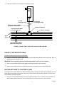
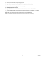
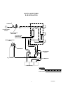
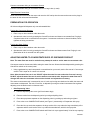
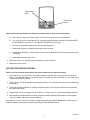
IMI CORNELIUS INC. One Cornelius Place Anoka, MN. 55303–6234 Telephone (800) 238–3600 Facsimile (612) 422–3232 Liquid Base Beverage Dispenser INSTALLATION & OPERATORS MANUAL Part No. 630460001 June 4 1996 Control Code A THIS DOCUMENT CONTAINS IMPORTANT INFORMATION This Installation Manual must be read and understood before starting to install or operate this equipment. IMI CORNELIUS INC; 1996 Printed in U.S.A. TABLE OF CONTENTS GENERAL DESCRIPTION . . . . . . . . . . . . . . . . . . . . . . . . . . . . . . . . . . . . . . . . . . . . . . . . . . . . . . . . . . . . . . . . . . . . . . 1 UNIT DESCRIPTION . . . . . . . . . . . . . . . . . . . . . . . . . . . . . . . . . . . . . . . . . . . . . . . . . . . . . . . . . . . . . . . . . . . . . . . . . DESIGN DATA . . . . . . . . . . . . . . . . . . . . . . . . . . . . . . . . . . . . . . . . . . . . . . . . . . . . . . . . . . . . . . . . . . . . . . . . . . . . . . . RECEIVING . . . . . . . . . . . . . . . . . . . . . . . . . . . . . . . . . . . . . . . . . . . . . . . . . . . . . . . . . . . . . . . . . . . . . . . . . . . . . . . . . UNPACKING AND INSPECTION . . . . . . . . . . . . . . . . . . . . . . . . . . . . . . . . . . . . . . . . . . . . . . . . . . . . . . . . . . . . . . . LOCATION SELECTION . . . . . . . . . . . . . . . . . . . . . . . . . . . . . . . . . . . . . . . . . . . . . . . . . . . . . . . . . . . . . . . . . . . . . . INSTALLATION . . . . . . . . . . . . . . . . . . . . . . . . . . . . . . . . . . . . . . . . . . . . . . . . . . . . . . . . . . . . . . . . . . . . . . . . . . . . . . CONCENTRATE SOURCE INSTALLATION . . . . . . . . . . . . . . . . . . . . . . . . . . . . . . . . . . . . . . . . . . . . . . . . . . . COUNTERTOP HOLE LOCATION (TUBING ACCESS) . . . . . . . . . . . . . . . . . . . . . . . . . . . . . . . . . . . . . . . . . MAKING WATER, CONCENTRATE, AND ELECTRICAL CONNECTIONS . . . . . . . . . . . . . . . . . . . . . . . . . COOLANT CONNECTION FOR HEAT EXCHANGER . . . . . . . . . . . . . . . . . . . . . . . . . . . . . . . . . . . . . . . . . . CONNECT CONCENTRATE TUBING . . . . . . . . . . . . . . . . . . . . . . . . . . . . . . . . . . . . . . . . . . . . . . . . . . . . . . . . SEALING UNIT BASE TO COUNTERTOP (USA) . . . . . . . . . . . . . . . . . . . . . . . . . . . . . . . . . . . . . . . . . . . . . . PREPARATION FOR OPERATION . . . . . . . . . . . . . . . . . . . . . . . . . . . . . . . . . . . . . . . . . . . . . . . . . . . . . . . . . . . ADJUSTING WATER-TO-CONCENTRATE RATIO OF DISPENSED PRODUCT . . . . . . . . . . . . . . . . . . . SETTING THE PORTION CONTROL . . . . . . . . . . . . . . . . . . . . . . . . . . . . . . . . . . . . . . . . . . . . . . . . . . . . . . . . SANITIZING THE SYSTEM (USA) . . . . . . . . . . . . . . . . . . . . . . . . . . . . . . . . . . . . . . . . . . . . . . . . . . . . . . . . . . . SANITIZING THE BAG-IN-BOX CONCENTRATE SYSTEMS . . . . . . . . . . . . . . . . . . . . . . . . . . . . . . . . . . . . . . . . 1 1 1 2 2 2 2 3 3 3 4 4 7 7 8 9 9 WARRANTY . . . . . . . . . . . . . . . . . . . . . . . . . . . . . . . . . . . . . . . . . . . . . . . . . . . . . . . . . . . . . . . . . . . . . . . . . . . . . . . . . 11 TABLE 1. DESIGN DATA . . . . . . . . . . . . . . . . . . . . . . . . . . . . . . . . . . . . . . . . . . . . . . . . . . . . . . . . . . . . . . . . . . . . . . . 1 TABLE 2. LOOSE-SHIPPED PARTS . . . . . . . . . . . . . . . . . . . . . . . . . . . . . . . . . . . . . . . . . . . . . . . . . . . . . . . . . . . . . 2 FIGURE 1. CONNECTION TO EXISTING SODA SYSTEM COOLANT . . . . . . . . . . . . . . . . . . . . . . . . . . . . . . . 4 IMI CORNELIUS INC. 1996 GENERAL DESCRIPTION UNIT DESCRIPTION The Three-Flavor Tower is compact and may be island-mounted or installed on a front or rear counter. The Three-Flavor Tower is designed to dispense three, portion controlled, noncarbonated drinks. One concentrate flavor is chilled by a heat exchanger. Cooling for the heat exchanger is provided by the existing soft drink system. DESIGN DATA Table 1. Design Data Overall Dimensions: Width 10.75 in. Height 26.25 in. Depth 9.12 in. Ambient Operating Temperature: 40 degrees F (4.4 degrees C) to 90 degrees F (32 degrees C) Electrical Requirements: 115VAC, 60HZ Inlet Water Requirements: Minimum Flow Pressure 40 psig Maximum Static Pressure 55 psig RECEIVING Each Unit is completely tested under operating conditions and thoroughly inspected before shipment. At time of shipment, the carrier accepts the Unit and any claim for damage in transit must be made with the carrier. Upon receiving Unit from the delivering carrier, carefully inspect the carton for visible indication of damage. Any damage or irregularities should be noted at this time (not later than 15 days from date of delivery) and immediately reported to the delivering carrier. Request a written inspection from the carrier’s claims inspector to substantiate claim. File claim with the delivering carrier not with IMI Cornelius Inc. 1 630460001 UNPACKING AND INSPECTION CAUTION: Unit must be lifted by the S/S tower to avoid damage. Do Not lift using valve housings. Unpack a Unit as follows: 1. Open carton. 2. Lift Unit from carton. 3. Retain installation manual, and loose shipped parts. 4. Carefully inspect Unit for evidence of damage. If evidence of damage is found, notify delivering carrier and file a claim against the carrier. 5. Remove loose-shipped parts from carton. Check contents per Table below. Table 2. Loose-Shipped Parts 90° Drain Elbow Installation Template Wire Harness Power Supply, 115/24 VAC, 75 VA Valve Decals Flavor Decals Installation Manual LOCATION SELECTION The Unit may be island-mounted or installed on a front or rear counter provided that the following requirements are satisfied. A hole must be cut in the countertop to permit access for the water, concentrate, drain tube and coolant tubing. WARNING: All electrical wiring must conform to national and local electrical codes. 1. Locate Unit near a grounded electrical outlet having a dedicated circuit fused at jjsr15 amps (slow-blow) for 115VAC units. Alternate protection using an equivalent HACR (US) circuit breaker may be used. The electrical supply for the tower is furnished by a 115/24 transformer which is mounted near the tower. 2. Locate Unit close to a water inlet supply line with pressure and flow as given in the listing of Physical Characteristics and Requirements. INSTALLATION CONCENTRATE SOURCE INSTALLATION IMPORTANT: This instruction does not include instructions for the installation of the concentrate source system. This should be done to suit the location. 2 630460001 COUNTERTOP HOLE LOCATION (TUBING ACCESS) 1. Using the template provided, layout the location of the access hole. 2. Cut the access hole in the counter. Be sure there are no sharp edges to damage the tubing. 3. Move the Unit into position over the hole and attach the tower to the counter. 4. Route all tubing (concentrate, water, coolant and drain) through the access in the countertop. MAKING WATER, CONCENTRATE, AND ELECTRICAL CONNECTIONS Make Water Connections as follows: CAUTION: If water source exceeds 65 psig a water pressure regulator kit must be used to ensure correct Unit operation. Refer to Installation Kits paragraph for part number. CAUTION: Do not use a saw to cut tubing, use a tubing cutter or knife to avoid contamination of tubing with particles of material. CAUTION: Water pipe connections and fixtures directly connected to a potable water supply shall be sized, installed and maintained according to federal, state, and local laws. 1. Check water pressure. If water pressure is greater than 65 psig, install a water pressure regulator. Regulate the water pressure to 50 psig. 2. Connect tubing marked “Water” to water source, but do not turn-on at this time. Additional tubing may have to be added to the existing water tubing from the dispenser. 3. If additional tubing is used, flush the tubing thoroughly by running four gallons (15 liters) of water to a drain or suitable container. 4. Connect to the tower water tubing. 5. Turn on the water supply and check for leaks. COOLANT CONNECTION FOR HEAT EXCHANGER Note: The inlet and outlet fittings on the Heat Exchanger are 1/2I. Use 1/2I tubing from the existing python to the Heat Exchanger. The tubing connections must be leak checked and then insulated to prevent condensation. Tubing, fittings, clamps and insulation to be supplied by the installer. 1. Select best location to tap into existing recirculating cold carbonated water tubing in the soft drink python. 2. The soft drink system must be shut down and all pressure relieved from the carbonator and associated carbonated water tubing. 3. Python insulation must be opened to permit access to the tubing. 4. Find the recirculating cold carbonated water line from the cooling unit. 5. Cut the cold carbonated water line and remove approximately 3I of the tubing to permit the installation of the elbows. 6. Connect tubing as shown in Figure 1. 3 630460001 7. Check all connections for leaks before insulating the tubing. To Heat Exchanger Inlet From Heat Exchanger Outlet Tubing must be insulated to prevent condensation Oetiker Clamps (8) Cold Carbonated Water From Cooling Unit Python Insulation Syrup Tubing Cold Carbonated Water Return to Cooling Unit FIGURE 1. CONNECTION TO EXISTING SODA SYSTEM COOLANT CONNECT CONCENTRATE TUBING Connect concentrate tubing to the Unit as follows: 1. Sanitize all concentrate systems after connecting concentrate tubing following instructions below. Refer to sanitizing procedure in this manual. IMPORTANT: All concentrate systems must be sanitized before unit is put into operation. 2. Route one concentrate tubing for each product up through the hole in the countertop. 3. Apply product decals from the kit to dispense switches to correspond to the product dispensed. SEALING UNIT BASE TO COUNTERTOP (USA) To comply with the requirements of the NSF International, (NSF), the base of a Unit must be sealed to the countertop and all access holes to the inside of the Unit must be closed off with a mastic material. To seal a Unit to the countertop, proceed as follows: 1. The tower must be fastened to the countertop using sheet metal screw or machine screws,whichever is desired. Before sealing the tower, locate and drill holes for screwing the tower to the countertop. 4 630460001 2. Carefully tilt the connected Unit up to expose the base. 3. Apply a silastic sealant e.g. Dow Corning RTV 731 or equivalent on all base edges. 4. Lower Unit into exact operating position on the countertop. 5. Fasten the tower to the countertop. 6. Apply additional sealant around the Unit so that the sealant has a minimum radius of 1/2 inch. 7. Seal the lines and plug the remaining opening with mastic material such as Permagum, or equivalent. NOTE: When Unit is lowered into place, do not move it, or seal will be broken. NOTE: All connections should be made before the Unit is sealed to the countertop. 5 630460001 MULTI-FLAVOR TOWER B-I-B INSTALLATION STRAINER POTABLE WATER SOURCE WATER PRESSURE REGULATOR COOLANT FROM EXISTING SOFT DRINK SYSTEM PRIMARY REGULATOR 70-80 PSI CHECK VALVE CONCENTRATE PUMP (3) CO2 CYLINDER CO2 MANIFOLD BAG-IN-BOX (3) LINE LEGEND CO2 PLAIN WATER CONCENTRATE 6 630460001 Connect concentrate tubing to concentrate Sources Connect concentrate tubing to concentrate sources for bag-in-box (or tank). Make Electrical Connections Mount the transformer beneath the tower and route the 24V lead up into the tower and connect to the plugs in the tower for the valves and merchandiser. PREPARATION FOR OPERATION All Units as shipped will dispense only non-carbonated drinks. Purging the Concentrate Systems 1. Place a cup or other container under the nozzle. 2. Operate each valve in turn by pressing the Cancel/Pour button and observe concentrate flow. Purging is completed when all air is removed from the system. If concentrate continues to show air bubbles, check tightness of tubing connections. Purging the Water System 1. Place a cup or other container under the nozzle. 2. Operate each valve in turn by pressing the Cancel/Pour button and observe water flow. Purging is completed when all air is removed from the system. ADJUSTING WATER-TO-CONCENTRATE RATIO OF DISPENSED PRODUCT Note: The water flow rate must be set before any attempt is made to set the water-to-concentrate ratio. Concentrate must be disconnected while setting the water flow rate. Water should be dispensed by pressing the Cancel/Pour switch on the control panel. 1. Using a graduated cup and a stop watch or second hand on your watch, set the flow rate to 2.5 ounces per second. This is equal to 10 ounces in 4 seconds Note: After the water flow rate is set, DO NOT adjust the water flow rate unless the flow rate is wrong. DO NOT adjust the water flow rate to set the water-to-concentrate ratio. Anytime the water flow rate is changed the water-to-concentrate ratio must be checked and adjusted as necessary. The water-to-concentrate ratio is measured by use of a ratio cup having two chambers into which the water and concentrate are dispensed. The ratio, if incorrect, is adjusted by turning the related concentrate flow regulator adjusting screw located on each concentrate valve. 1. Dole Dispensing Valve A. Remove dispensing valve cover (pull from bottom edge). B. Remove nozzle from the dispensing valve by turning and pulling down. C. Place the syrup/water separator on the dispensing valve by pushing up and turning to tighten. D. Press valve cover CANCEL/POUR switch (see Figure 1) momentarily to fill separator with syrup. E. Place the brix cup under the separator, the large section of the cup under the large round body of the separator and the small section of the cup under the extended arm, which is the syrup tube. F. Press valve cover CANCEL/POUR switch and fill the brix cup to approximately 3/4 of the cup capacity. 7 630460001 LED Indicator Light Cancel/Pour Switch Figure 1 Note: Check local specifications for dispensed product water to syrup ratio specifications. G. If the ratios are correct, proceed to Step I. If the ratios are not correct, proceed to step H. H. Turn valve syrup flow control labeled “S4” (right-side control) adjusting screw to the left (COUNTERCLOCKWISE) for less syrup or to the right (CLOCKWISE) for more syrup. I. Remove the syrup/water separator by turning and pulling down. J. Reinstall the nozzle by pushing up and turning until it is locked. K. Repeat Steps E through J until the ratios are correct on all dispensing valves. Syrup calibration check is complete. L. Install dispensing valve front cover. 2. Adjust the ratios for the remaining valves following the same procedure. 3. Replace the valve covers. SETTING THE PORTION CONTROL Note: In case of electrical power failure, the portion control has full memory function. 1. Press and hold “S” (small) and “XL” (extra-large) dispense switches at the same time on the front cover until for 3 seconds, after that time the portion control ”set mode” has been activated. The “set mode” will be confirmed by a flashing red LED. 2. Fill the cup to be used for small drinks with desired amount of ice, then place the cup under the dispensing valve nozzle. 3. Press and hold switch labeled “S” (small) on dispensing valve cover until cup is filled to the desired level, then release the switch. 4. Repeat Steps 2 and 3 to program the “M” (medium), “L” (large), and “XL” (extra-large) dispense switches. 5. After adjusting all dispensed drink volumes, press and release CANCEL/POUR switch to cancel portion control “set mode” and return to normal operation. Dispensing of a portion control drink may be stopped by pressing the CANCEL/POUR switch. Drinks may be manually dispensed (non-portion control) by pressing the CANCEL/POUR switch. 8 630460001 SANITIZING THE SYSTEM (USA) IMPORTANT: Only trained personnel should perform sanitizing procedures. WARNING: Wear protective eyewear to avoid eye injury. The syrup systems must be sanitized once every six months; whenever there is a flavor change, or an off flavor is noted in the product. This is the ‘‘ambient’’ sanitizing procedure whereby syrup is first flushed from the system with water, then a detergent is introduced, followed by a second water flush. A sanitizer is next placed in the system and it is finally purged with concentrate. SANITIZING THE BAG-IN-BOX CONCENTRATE SYSTEMS This is a procedure for sanitizing concentrate systems of the Liquid Base Beverage Dispenser. SANITIZE THE BAG-IN-BOX SYSTEM AS FOLLOWS: 1. Disconnect the concentrate tube-end connectors from the bag-in-box containers. 2. Wash each tube-end fitting in warm water to remove any concentrate accumulation. 3. Install a bag valve (this can be cut from an empty bag-in-box container) on each concentrate tube-end connector. This opens the tube-end fitting so detergent, sanitizing solution and flush water can be pumped into the system. 4. Fill a clean plastic 5-gallon container with potable (drinking) water. 5. Place the tube-end connectors (with installed bag valves) into the water. 6. Place a waste container under the valve dispensing nozzle. 7. Operate each concentrate valve by pressing the Canel/Pour button to cause concentrate to flow from the nozzle. 8. Operate each valve until only water is dispensed. 9. Remove the concentrate tube-end connectors from the water. 10. Fill the 5-gallon container with potable (drinking) water at room temperature (70 degrees to 100 degrees F) and add 3/4 ounce per gallon of water (6 ml per liter) of Diversey DIVOFLOW 185, or equivalent detergent. Detergent must contain sodium hydroxide, be non-perfumed, and have low-sudsing characteristics. The detergent should be able to be rinsed off easily. The sodium hydroxide should be between 2 percent and 10 percent in the concentrated detergent. 11. Mix the contents of the container thoroughly. 12. Place the concentrate tube-end connectors (with bag valves installed) into the detergent. 13. Operate each valve until the water is displaced by the detergent. CAUTION: To avoid damage to metallic parts of the system, do not allow the detergent solution to remain in a concentrate system longer than 15 minutes. 14. Allow the detergent to remain in the concentrate tubing for at least 10 minutes, but no longer than 15 minutes. 9 630460001 15. Remove the tube-end connectors from the detergent. 16. Dispose of unused detergent in a sanitary sewer, not in a storm drain. Wash the container thoroughly. 17. Fill the 5-gallon container with potable (drinking) water. Place the tube-end connectors in the water. 18. Hold each dispensing valve open until the detergent is displaced by the water. WARNING: Phenolphthalein must be kept away from children. It is a powerful laxative and may cause serious illness if taken internally. 19. Dispense a one-ounce sample of water from the nozzle. Test the sample using a drop of phenolphthalein indicator. (This indicator becomes pink-colored in the presence of even small amounts of detergent) When the indicator remains clear, all detergent has been removed. 20. Remove the tube-end connectors from the water. 21. Fill the 5-gallon container with 4 gallons (15.1 liters) of water at a temperature between 70 degrees F. to a maximum of 100 degrees F. 22. Add 1.0 oz. (29.57 ml) of H.B. Fuller Monarch C–S or equivalent sanitizer [to provide a 200 ppm (200 mg/liter) active quaternary sanitizing solution] to the container. Mix thoroughly. 23. Place the concentrate tube-end connectors in the sanitizing solution. 24. Operate each valve until only the sanitizing solution is dispensed. CAUTION: To avoid damage to metallic parts of the system, do not allow the sanitizing solution to remain in the concentrate systems longer than 15 minutes. 25. Allow the sanitizing solution to remain in the concentrate systems from 8 to 10 minutes. 26. Remove concentrate tube-end connectors from the sanitizing solution and remove the bag valves from the tube-end connectors. (Save the bag valves). 27. Connect each concentrate tube-end connector to the preselected concentrate source. 28. Operate each valve until the concentrate purges the sanitizer from the tubes, and only concentrate is dispensed. 29. Dispense and taste each product for off-taste. 30. Dispose of the waste sanitizing solution in the sanitary sewer, (not in storm drain). Rinse both containers. 10 630460001 WARRANTY IMI Cornelius Inc. warrants that all equipment and parts are free from defects in material and workmanship under normal use and service. For a copy of the warranty applicable to your Cornelius, Remcor or Wilshire product, in your country, please write, fax or telephone the IMI Cornelius office nearest you. Please provide the equipment model number, serial number and the date of purchase. IMI Cornelius Offices AUSTRALIA D P.O. 210, D RIVERWOOD, D NSW 2210, AUSTRALIA D (61) 2 533 3122 D FAX (61) 2 534 2166 AUSTRIA D AM LANGEN FELDE 32 D A-1222 D VIENNA, AUSTRIA D (43) 1 233 520 D FAX (43) 1-2335-2930 BELGIUM D BOSKAPELLEI 122 D B-2930 BRAASCHAAT, BELGIUM D (32) 3 664 0552 D FAX (32) 3 665 2307 BRAZIL D RUA ITAOCARA 97 D TOMAS COELHO D RIO DE JANEIRO, BRAZIL D (55) 21 591 7150 D FAX (55) 21 593 1829 ENGLAND D TYTHING ROAD ALCESTER D WARWICKSHIRE, B49 6 EU, ENGLAND D (44) 789 763 101 D FAX (44) 789 763 644 FRANCE D 71 ROUTE DE ST. DENIS D F-95170 DEUIL LA BARRE D PARIS, FRANCE D (33) 1 34 28 6200 D FAX (33) 1 34 28 6201 GERMANY D CARL LEVERKUS STRASSE 15 D D-4018 LANGENFELD, GERMANY D (49) 2173 7930 D FAX (49) 2173 77 438 GREECE D 488 MESSOGION AVENUE D AGIA PARASKEVI D 153 42 D ATHENS, GREECE D (30) 1 600 1073 D FAX (30) 1 601 2491 HONG KONG D 1104 TAIKOTSUI CENTRE D 11-15 KOK CHEUNG ST D TAIKOKTSUE, HONG KONG D (852) 789 9882 D FAX (852) 391 6222 ITALY D VIA PELLIZZARI 11 D 1-20059 D VIMARCATE, ITALY D (39) 39 608 0817 D FAX (39) 39 608 0814 NEW ZEALAND D 20 LANSFORD CRES. D P.O. BOX 19-044 AVONDALE D AUCKLAND 7, NEW ZEALAND D (64) 9 8200 357 D FAX (64) 9 8200 361 SINGAPORE D 16 TUAS STREET D SINGAPORE 2263 D (65) 862 5542 D FAX (65) 862 5604 SPAIN D POLIGONO INDUSTRAIL D RIERA DEL FONOLLAR D E-08830 SANT BOI DE LLOBREGAT D BARCELONA, SPAIN D (34) 3 640 2839 D FAX (34) 3 654 3379 USA D ONE CORNELIUS PLACE D ANOKA, MINNESOTA D (612) 421-6120 D FAX (612) 422-3255 LD004 4/21/98 11 630460001


![Service Manual VA13 Carbonator [ 002818 ]](http://vs1.manualzilla.com/store/data/006013608_1-0f8f87056a0ab013b1dd01dac3912d47-150x150.png)