1
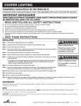
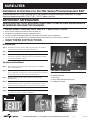
SURE-LITES
Installation Instructions for the PHL Series Photoluminescent EXIT
Photoluminescent EXIT sign, requiring only 5 foot-candles of external fluorescent illumination to charge.
Operating temperatures from 10-40°C (50 – 104°F), Indoor Use Only.
IMPORTANT SAFEGUARDS
WHEN USING ELECTRICAL EQUIPMENT, BASIC SAFETY PRECAUTIONS SHOULD ALWAYS
BE OBSERVED INCLUDING THE FOLLOWING:
1.
2.
3.
4.
5.
6.
READ AND FOLLOW ALL SAFETY INSTRUCTIONS
Do not use this equipment for other than the intended use.
Installation is to be performed only by qualified personnel.
Install in accordance with National Electric Code and local regulatory agency requirements.
The use of accessory equipment not recommended by the manufacturer may cause an unsafe condition.
SAVE THESE INSTRUCTIONS.
INSTALLATION
Step 1. Separate the two EXIT panels by sliding the panel facing the installer to
the left, and the rear panel to the right (see illustration 1).
C
E
Step 2. Remove unneeded directional chevrons from the sign (see illustration 2).
Step 3. Secure the remaining chevrons by bending the outer tabs at the point of
the chevron on the back of the EXIT panel. Do not bend the two inside
chevrons (see illustration 3 and 4).
Top Mount or End Mount
Step 1. Reassemble the two panels by performing the reverse of Installation
Step 1 (see illustration 5).
Step 2. Align the four holes on the U-channel insert to the matching holes on the
sign, in the desired mounting location. Attach the aluminum U-channel to
the sign using the four screws provided (see illustration 6).
Step 3. Apply the silver screw hole covering strips to the unused holes
(see illustration 7).
Step 4. Affix the external aluminum mounting bracket to the wall or ceiling, using
suitable mounting means. If attaching the mounting bracket to a drop
ceiling, use the drop ceiling reinforcement plate and screws provided.
A
B
D
INCLUDED HARDWARE:
A. U-channel
B. Mounting Bracket
C. End Caps
D. Drop Ceiling Reinforcement Plate
E. Hardware Package
Step 5. Slide the U-channel into the mounting bracket (see illustration 8).
Step 6. Snap the plastic endcaps into both sides of the mounting bracket/
U-channel assembly to complete the installation.
TOP VIEW
Illustration 1
Illustration 2
Illustration 3 & 4
Customer First Center 1121 HIGHWAY 74 SOUTH PEACHTREE CITY, GA 30269
3/07
11554915
SURE-LITES
Surface Mount
Step 1. Using a drill, self drilling screws, or other appropriate means, create mounting holes on the back panel in the necessary locations (see illustration 9).
Step 2. Attach to the wall using suitable mounting means.
Step 3. Reassemble the two panels by performing the reverse of Installation Step 1 (see illustration 10).
Step 4. Apply the silver screw hole covering strips to the edges.
Maintenance
Periodically clean letters with a damp cloth.
TOP VIEW
Illustration 5
Illustration 6
Illustration 7
TOP VIEW
Illustration 8
Illustration 9
Illustration 10
Customer First Center 1121 HIGHWAY 74 SOUTH PEACHTREE CITY, GA 30269
3/07
11554915