1
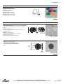
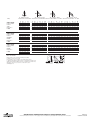
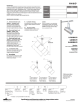
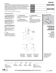
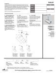
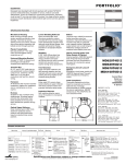
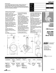
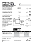
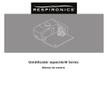
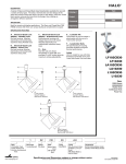
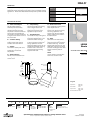
HALO
®
DESCRIPTION
A series of understated, balanced lampholders that come in a variety of
lamp types. The Stasis family of lampholders feature die cast and extruded
bodies with elegant free flowing lines. Ideal for accent and display lighting
applications. This Ceramic Metal Halide T6 lampholder is perfect for those
applications where performance is required from a discreet source.
Type
Catalog #
Project
Date
Comments
Prepared by
SPECIFICATION FEATURES
A ... Quick-Lock Adapter
Die cast adapter attaches
electrically and mechanically
anywhere along track. Includes
discreet locking tab that locks
lampholder on track and allows for
easy removal and repositioning.
Two position conductor allows use
in single circuit and either circuit of
two circuit track.
B ... Lockable Aiming
Lampholder tilt and rotation can be
locked in place easily with the
included 1.5mm allen wrench.
C ... Switch
On-off switch allows power to be
turned off during lamp
replacement on individual
lampholders.
E ... Lamp Housing
Aluminum die cast lamp housing
has an integral reflector and
adjustable light center optic
allowing the light beam to be
adjusted from spot-to-flood.
F ... Lampholder Arm
Arm allows the lamp housing tilt to
adjust +/-90°. It also pivots +/-90°
around the ballast housing. This
enables the ballast housing to
remain static on the track creating
a clean look, while providing full
aiming capabilities. The arm
employs graduations every 15° for
precise and repeatable tilt aiming.
Indicator mark on the bottom
ensures perfect lamp housing
alignment with track.
H ... Bezel
Removable front bezel features
positive threaded engagement and
holds the containment lens with a
threaded media ring. The bezel
accepts L275 cube cell louver and
L200 media, including color filters
and beam modifying lenses. Bezel
accepts a total two pieces of
media.
L5056
Stasis
39 and 70W Ceramic Metal Halide
T6
Labels
UL/c-UL Listed for use with Halo
Power-Trac and Lazer Track.
D ... Ballast Housing
Die cast and extruded aluminum
housing incorporates the lamp
control circuit.
A
Power-Trac
F
B
39W
5-5/8"
[143mm]
D
70W
6-3/4”
[171mm]
C
B
G ... Beam Focus Knob
Knob rotates 90° providing infinite
beam adjustment from
spot-to-flood. A cool-to-the-touch
silicone cover allows convenient,
hot aiming capabilities. The
silicone cover has an embossed
graphic indicating turn direction
for desired beam.
G
E
2-3/8"
[60mm]
7-7/16"
[189mm]
H
Energy Data
4-13/16"
[106mm]
Input Power:
Power Factor:
Input Current:
39W: 45W
70W: 77W
>0.95
39W: 0.37A
70W: 0.65A
Harmonic Distortion: <10%
L
Track
L=Halo Track
5
Lamp Type
5=Metal
Halide
05
Series
05=Stasis
6
Lamp
6 =T6 CMH
(Lamp Not
Included)
Wattage
39 = 39W T6 CMH
70 = 70W T6 CMH
Finish
P=White
MB=Black
AH =Aluminum
Haze
Accessories
L200=Series Lenses
L275 =Cube Cell Louver
Specifications and Dimensions subject to change without notice.
Consult your representative for additional options and finishes.
ADV070779
11/06/2007 5:13:50 PM
L505639 L505670
ACCESSORIES
.
ACCESSORIES
L200 Color Filters
ACCESSORIES
L211=Medium Pink Color Filter
L212=Warm
L 2 0 0 C o lRed
o r Color
F i l t eFilter
rs
L214=Ultraviolet
Filter
L211=Medium Pink
Color Filter
L220=Daylight
L212=Warm
L 2 0 0 C o l Red
oBlue
r FColor
iColor
l t e Filter
r sFilter
L221=Medium
Blue
Color
Filter
L214=Ultraviolet
Filter
L211=Medium Pink
Color Filter
L231=Medium
Amber
ColorFilter
Filter
L220=Daylight
Blue
Color
L212=Warm Red Color Filter
L241=Medium
Green
ColorFilter
Filter
L221=Medium
Blue
Color
L214=Ultraviolet Filter
L231=Medium
Color
Filter
L220=Daylight Amber
Blue Color
Filter
L241=Medium
ColorFilter
Filter
L221=Medium Green
Blue Color
L231=Medium Amber Color Filter
L241=Medium Green Color Filter
4 11/16"
[19mm]
1/4"
[6mm]
4 11/16"
[19mm]
4 11/16"
[19mm]
1/4"
[6mm]
L200 Series Color
Filters
L200 Series Color
Filters
L200 Series Color
Filters
1/4"
[6mm]
.
L200 Series Optical Lenses
L210=Linear Spread Lens
L210
55°
L 2 0lens
0 S fans
e r i eout
s Olight
p t i cbeam
al Le
n s-e27
s 1/2° each side of
center
L210=Linear Spread Lens
L 2 0 0lens
S efans
r Spread
i e sout
O light
pLens
t i c beam
a l L e55°
n s e- s
L210
27 1/2° each side of
L215=Radial
center
L215
lens spreads
light
beam 30° in all directions - 15° on
L210=Linear
Spread
Lens
all
sides
of fans
center
L210
lens
out light
beam 55° - 27 1/2° each side of
L215=Radial
Spread
Lens
center
L215
lens spreads
L250=Linear
Spreadlight
Lensbeam 30° in all directions - 15° on
all
sides
center
L250
lens of
spreads
light
beam in one direction
L215=Radial
Spread
Lens
L215 lens spreads
light
beam 30° in all directions - 15° on
L250=Linear
Spread
Lens
L265=Prismatic
Spread
Lens
all sides
center
L250
lensofspreads
light beam
one direction
L265
Spreads
light beam
in all in
directions
L250=Linear Spread
Lens
L265=Prismatic
Spread
Lens
L250 Spreads
lens spreads
beam
one direction
L265
lightlight
beam
in allindirections
L265=Prismatic Spread Lens
L265 Spreads light beam in all directions
4 3/4" OD (121mm). Black finish 1/2"
cells
directing
light
L 2 7for
5 C
ube Ce
l l Land
o u veliminating
er
glare.
4 3/4" OD (121mm). Black finish 1/2"
1/4"
[6mm]
1/4"
[6mm]
4 11/16"
[119mm]
1/4"
[6mm]
1/4"
[6mm]
4 11/16"
[119mm]
1/4"
[6mm]
1/4"
[6mm]
4 11/16"
[119mm]
L200 Lenses
L200 Lenses
L275 Cube Cell Louver
L275
u b e C elight
ll Lo
u veliminating
er
cells
forCdirecting
and
glare.
4 3/4" OD (121mm). Black finish 1/2"
cells for directing light and eliminating
glare.
L200 Lenses
4 3/4"
(121mm)
4 3/4"
(121mm)
4 3/4"
(121mm)
3/8"
(10mm)
3/8"
(10mm)
3/8"
(10mm)
7/16"
(11mm)
7/16"
(11mm)
7/16"
(11mm)
L275 Cube
Louver
L275 Cube
Louver
L275 Cube
Louver
Specifications and Dimensions subject to change without notice.
HALO Track • Customer First Center • 1121 Highway 74 South • Peachtree City, GA 30269 • TEL 770.486.4800 • FAX 770.486.4801
ADV070779
11/06/2007 5:13:50 PM
45°
Lamp
CMH70/T6/830
Lumens: 6600
Lumens
SPOT
Report No.:
P10496
CMH70/T6/830
Lumens: 6600
Lumens
NARROW
FLOOD
Report No.:
P10497
CMH70/T6/830
Lumens: 6600
Lumens
FLOOD
Report No.:
P10498
0° Aiming Angle
Horizontal Footcandles
D
9.0
10.0
13.0
16.0
20.0
30° Aiming Angle
30° Aiming Angle
H o r i z o n t a l F o o t c a n d l e s Ve r t i c a l F o o t c a n d l e s o n Wa l l
FC
519
420
249
164
105
L
1.6
1.8
2.4
2.9
3.7
W
1.6
1.8
2.4
2.9
3.7
D
9.0
10.0
13.0
16.0
20.0
FC
337
273
162
107
68
L
2.3
2.6
3.3
4.1
5.2
W
1.9
2.2
2,9
3.4
4,3
D
FC
9.0 133
10.0 108
13.0 64
16.0 42
20.0 27
L
4.3
4.8
6.2
7.7
9.6
W
4.3
4.8
6.2
7.7
9.6
D
9.0
10.0
13.0
16.0
20.0
FC
87
70
42
27
18
L
5.7
6.3
8.2
10.1
12.6
D
FC
L
8.0 125 5.0
9.0 99
5.7
10.0 90
6.3
13.0 47
8.2
16.0 31 10.1
20.0 20 12.6
W
5.0
5.7
6.3
8.2
10.1
12.6
D
9.0
10.0
13.0
16.0
20.0
FC
64
52
31
20
13
L
7.0
7.8
10.1
12.5
15.6
S
2.7
3.0
3.9
4.8
6,0
CB
5.2
5.8
7.5
9.2
11.5
D
FC
5.0 225
6.0 156
8.0 88
10.0 56
12.0 39
L
3.7
4.4
5.8
7.3
8.8
W
1.8
2.2
2.9
3.6
4.4
W
S
CB
5.3 8.1 5.2
5.9 9.0 5.8
7.6 11.7 7.5
9.4 14.4 9.2
11.7 18.0 11.5
D
5.0
6.0
8.0
10.0
12.0
FC
77
54
30
19
13
L
6.9
8.3
11.1
13.9
16.7
W
S
CB
4.6 6.5 8.7
5.6 7.8 10.4
7.4 10.4 13.9
9.3 13.0 17.3
11.1 15.6 20.8
D
FC
L
5.0 131 4.9
6.0 91
5.0
8.0 51
7.8
10.0 33
9.8
12.0 23 11.8
W
S
CB
4.4 6.0 5.0
5.3 7.2 6.0
7.1 9.6 8.0
8.9 12.0 10.0
10.7 14.4 12.0
W
6.9
7.6
9.9
12.2
15.3
D
5.0
6.0
8.0
10.0
12.0
FC
74
51
29
18
13
L
6.4
7.7
10.3
12.9
15.4
W
S
CB
5.1 7.5 8.7
6.1 9.0 10.4
8.1 12.0 13.9
10.1 15.0 17.3
12.1 18.0 20.8
D
FC
L
5.0 131 4.9
6.0 91
5.0
8.0 51
7.8
10.0 33
9.8
12.0 23 11.8
W
S
CB
4.4 6.0 5.0
5.3 7.2 6.0
7.1 9.6 8.0
8.9 12.0 10.0
10.7 14.4 12.0
S
CB
9.9 5.2
11.0 5.8
14.3 7.5
17.6 9.2
22.0 11.5
S
2.5
3.0
4.0
5.0
6.0
CB
8.7
10.4
13.9
17.3
20.9
45° Aiming Angle
Ve r t i c a l F o o t c a n d l e s o n Wa l l
D
5.0
6.0
8.0
10.0
12.0
FC
594
2.3
232
149
103
L
1.9
1.6
3.1
3.8
4.6
W
1.4
2.4
2.2
2.7
3.3
S
2.0
2.4
3.2
4.0
4.8
CB
5.0
6.0
8.0
10.0
12.0
Notes and Definitions:
Beam spread is to 50% center beam candlepower (CBCP.)
D=Distance in feet to floor or wall.
FC=Footcandles on floor or wall at center beam aiming location.
L =Effective Visual Beam length in feet (50% of maximum footcandle level.)
W=Effective Visual Beam width in feet (50% of maximum footcandle level.)
CB=Distance in feet across or down to center beam location.
39W Multiplier = .5
Specifications and Dimensions subject to change without notice.
HALO Track • Customer First Center • 1121 Highway 74 South • Peachtree City, GA 30269 • TEL 770.486.4800 • FAX 770.486.4801
ADV070779
11/06/2007 5:13:50 PM