1
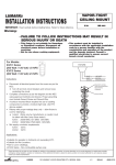
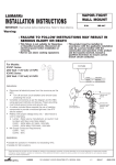
PORTFOLIO
Installation Instructions for H17500QT4 and H17250QT4 Commercial Surface
Cylinders and for H77500QT4 and H77250QT4 Wall Mount Cylinders
Figure 1
Figure 2
Pendant Kit, H836
(Sold Separately)
Housing
Heat Sink and
Lamp Assembly
Mounting Screws
Upper Reflector
Assembly
Lower Reflector
Assembly
CAUTION: To avoid possible electrical shock, be sure that power supply is
turned off before installing or servicing this fixture.
Figure 3
Heat Sink
STEP 1:
STEM/CANOPY MOUNT (Figure 1)
• Secure canopy assembly to the outlet box with screws (included
in the Pendant Kit).
• Attach stem to the canopy and to housing.
• Make wiring connections.
SURFACE MOUNT
• The cylindrical housing is attached to the outlet box (on ceiling)
by using (2) mounting screws shown in Figure 2.
• Make wiring connections.
Lamp
Upper Reflector
Assembly
Reflector
Opening
STEP 2: To Install Upper Reflector: Cut plastic tie wrap securing heat sink to
bracket. Install quartz mini-can frosted lamp. Make sure the lamp
wattage matches the markings on the heat sink.
WARNING: DO NOT handle quartz lamps with bare hands.
Grease from fingerprints may cause premature end of life or
shattering of lamp.
Install heat sink to upper reflector assembly carefully guiding lamp
into reflector opening (Figure 3). Rotate heat sink until flanges are
seated under retention springs(Figure 4). Insert this completed
assembly into the cylindrical housing until seated securely.
Customer First Center
1121 Highway 74 South Peachtree City, GA 30269
12/18/06
704244
PORTFOLIO
Figure 4
TO INSTALL LOWER REFLECTOR ASSEMBLY
STEP 3: Attach safety tether from lower reflector assembly to mounting bracket inside the can via clip.
Reflector Assembly is held in place with torsion springs that pass through slots inside the can. (Figure 5)
WALL MOUNT ONLY
STEP 4: Install wall housing/wall bracket shown in Figure 6 over the outlet box on the wall.
STEP 5: Using the (2) screws shown in Figure 5, secure the assembly to the outlet box.
STEP 6: Make wiring connections.
STEP 7: Follow steps 2-3 for trim installation.
RELAMPING: Allow sufficient time for the lamp to cool. Relamping can be performed from below the
fixture.
To relamp from below the fixture: Remove lower trim and then remove
upper reflector by pressing the four retention springs inward (Figure 7).
Rotate heat sink to clear retention springs and carefully separate from
reflector assembly. Replace lamp and reassemble as described in steps
1-4.
Figure 5
CLEANING: First, gently wipe with a soft, clean, dry lint-free cloth to
remove loose dust. Then, use mild detergent solution on a soft cloth to
remove finger prints and stains. Rinse with clean, soft water and dry with
lint-free cloth.
Figure 6
For Clarity, Housing
Can is not shown
Screws
Hole that
safety tether
clips
Slots that Torsion
Spring Hooks into
Wall Bracket
Clip
Screws
Safety
Tether
WALL MOUNT ONLY
Torsion
Springs
Customer First Center
Figure 7
Depress these 4 retention springs
to install/remove the upper trim.
1121 Highway 74 South Peachtree City, GA 30269
12/18/06
704244