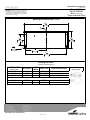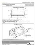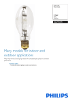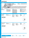
1
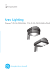
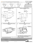
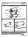
Installation Instructions
Sheet 1 of 3
Roundel, XL
IN/OUTDOOR
BI (Base, Integral)
Visor and Non-Visor
Warning: Before starting any work ensure
that all sources of power are turned off. All
work must meet local/national codes and be
performed by a certified electrician. Do not
mount fixtures vertically.
Exploded View and Part Call-Out
Fixture door
Captive door
screws
(x10)
3/8-16 x1"
Hex End bolt
(2x)
End cap
1/4-20 x1"
Screw
(4x)
1/4-20 x1"
Aiming screw
(2x)
Ballast enclosure
cover plate
Integral ballast
enclosure
Mounting
brackets (2x)
1.
1/4-20 x1"
Screw
(4x)
Securing Mounting Brackets
2.
#10-32 x 1/2"
Pan head screws
(x12)
Securing Ballast Enclosure to Surface
1/4-20 nut
(x4)
Insert driver through
mounting holes in bracket
to secure brackets to ballast
enclosure.
1. Using 1/4-20 x1" screws, secure mounting brackets to bottom
of ballast enclosure.
2. Brackets can be attached as shown or reversed allowing
access to bolts from side of fixture.
ADY080863 REV A(ECN080377)
Pre-installed
1/4-20 bolts
(x4)
1. After securing mounting brackets to ballast enclosure, slide
brackets over pre-installed 1/4-20 bolts in mounting
surface.(Refer to page 3 for mounting dimensions)
2. Using appropriate nuts, secure ballast enclosure to surface.
Installation Instructions
Sheet 2 of 3
Roundel, XL
IN/OUTDOOR
BI (Base, Integral)
Visor and Non-Visor
Warning: Before starting any work ensure
that all sources of power are turned off. All
work must meet local/national codes and be
performed by a certified electrician. Do not
mount fixtures vertically.
3
Securing Yoke Arms to Ballast Enclosure
1/4-20 x 1"
Pan head screws
(4x)
3/8-16 x 1"
Hex end bolt
(x2)
Yoke arms
(2x)
Securing Fixture Head
4
Aiming screw
spacer
(x2)
Fixture Wire
End Cap
1/4-20 x1"
Aiming screw
(x2)
1. Attach yoke arms to ballast enclosure using all four 1/4-20x
1" Pan head screws.
5
1. While firmly supporting fixture head, secure to yoke arms using
both 3/8-16 x1" hex end bolts.
2. Slide spacers between fixture head and yoke and secure
fixture head position using both 1/4-20 x1" aiming screws.
3. Insert fixture wire into compression fitting in ballast enclosure.
4. Replace end cap.
Aiming the Fixture
6
Wiring the Fixture
Yoke arm
indicator
Fixture head
indicator
Ballast
cover plate
End cap
(x2)
#10-32 x1/2"
Pan head screws
(x12)
1. Loosen all 12 screws and remove ballast box cover plate.
2. Attach appropriate wires ensuring all connections are properly
matched.
3. Secure ballast box cover plate using all twelve screws.
ADY080863 REV A(ECN080377)
1. To aim fixture, unscrew end caps from fixture. Loosen both
1/4-20 x1" aiming screws on both sides of fixture. When yoke
indicator and fixture head indicator are lined up, the slope of
the lens face is 40-degrees. Each subsequent notch is an
additional 10-degrees.
2. When fixture is rotated to desired angle, re-tighten set screws
and replace end caps.
Installation Instructions
Sheet 3 of 3
Roundel, XL
IN/OUTDOOR
BI (Base, Integral)
Visor and Non-Visor
Warning: Before starting any work ensure
that all sources of power are turned off. All
work must meet local/national codes and be
performed by a certified electrician. Do not
mount fixtures vertically.
Mounting Plate Dimensions In[mm]
3
27 4 "
704.85
CL
1
62"
1
10 4 "
165.10
260.35
13
32 "
10.32
(4x)
7
12 8 "
327.03
3
25 4 "
654.05
Lamping Size Chart
(lamps provided by others)
FIXTURE SIZE
(inches/ m m )
WATTAGE
27/ 685.8
27/ 685.8
27/ 685.8
250W
400W
400W
27/ 685.8
27/ 685.8
750W
1000W
ADY080863 REV A(ECN080377)
# OF
LAMP TYPE
LAMPS
1
ED28
1
ED28/BT37
2
ED28/BT37
1
1
BT37
BT37
LAMP DESCRIPTION
Metal Halide
Metal Halide
Metal Halide
Metal Halide
Metal Halide
LAMP
(not to scale)