1
Model C160 / C180 / C200 / C240 / C360
Owner’s Guide
HP Part No. A4200-90050
Edition E1298
Printed in U.S.A.
Copyright Hewlett-Packard Co. 1998
Printing History
First Printing: December 1998
UNIX is a registered trademark in the United States and other countries,
licensed exclusively through X/Open Company Limited.
NOTICE
The information contained in this document is subject to change without
notice.
HEWLETT-PACKARD WARRANTY STATEMENT
HP PRODUCT
DURATION OF WARRANTY
C160/C180/C200/C240/C360
one year
1. HP warrants HP hardware, accessories and supplies against defects in
materials and workmanship for the period specified above. If HP receive
notice of such defects during the warranty period, HP will, at its option,
either repair or replace products which prove to be defective. Replacement
products may be either new or like-new.
2. HP warrants that HP software will not fail to execute its programming
instructions, for the period specified above, due to defects in material and
workmanship when properly installed and used. If HP receives notice of
such defects during the warranty period, HP will replace software media
which does not execute its programming instructions due to such defects.
3. HP does not warrant that the operation of HP products will be uninterrupted or error free. If HP is unable, within a reasonable time, to repair or
replace any product to a condition as warranted, customer will be entitled to
a refund of the purchase price upon prompt return of the product.
4. HP products may contain remanufactured parts equivalent to new in performance or may have been subject to incidental use.
5. The warranty period begins on the date of delivery or on the date of installation if installed by HP. If customer schedules installation or causes installation by HP to be delayed more than 30 days after delivery, warranty begins
on the 31st day from delivery.
6. Warranty does not apply to defects resulting from (a) improper or inadequate maintenance or calibration, (b) software, interfacing, parts or supplies
not supplied by HP, (c) unauthorized modification or misuse, (d) operation
outside of the published environmental specifications for the product, or (e)
improper site preparation or maintenance.
7. TO THE EXTENT ALLOWED BY LOCAL LAW, THE ABOVE WARRANTIES ARE EXCLUSIVE AND NO OTHER WARRANTY OR CONDITION, WHETHER WRITTEN OR ORAL, IS EXPRESSED OR
IMPLIED AND HP SPECIFICALLY DISCLAIMS ANY IMPLIED WARRANTIES OR CONDITIONS OF MERCHANTABILITY, SATISFACTORY QUALITY, AND FITNESS FOR A PARTICULAR PURPOSE.
8. HP will be liable for damage to tangible property per incident up to the
greater of $300,000 or the actual amount paid for the product that is the subject of the claim, and for damages for bodily injury or death, to the extent
that all such damages are determined by a court of competent jurisdiction to
have been directly caused by a defective HP product.
9. TO THE EXTENT ALLOWED BY LOCAL LAW, THE REMEDIES IN
THIS WARRANTY STATEMENT ARE CUSTOMER'S SOLE AND
EXCLUSIVE REMEDIES. EXCEPT AS INDICATED ABOVE, IN NO
EVENT WILL HP OR ITS SUPPLIERS BE LIABLE FOR LOSS OF
DATA OR FOR DIRECT, SPECIAL, INCIDENTAL, CONSEQUENTIAL
(INCLUDING LOST PROFIT OR DATA), OR OTHER DAMAGE,
WHETHER BASED IN CONTRACT, TORT, OR OTHERWISE.
FOR CONSUMER TRANSACTIONS IN AUSTRALIA AND NEW
ZEALAND: THE WARRANTY TERMS CONTAINED IN THIS STATEMENT, EXCEPT TO THE EXTENT LAWFULLY PERMITTED, DO NOT
EXCLUDE, RESTRICT OR MODIFY AND ARE IN ADDITION TO THE
MANDATORY STATUTORY RIGHTS APPLICABLE TO THE SALE OF
THIS PRODUCT TO YOU.
iii
This document contains proprietary information that is protected by copyright. All rights reserved. No part of this document may be photocopied,
reproduced or translated to another language without the prior written consent of Hewlett-Packard Company.
RESTRICTED RIGHTS LEGEND. Use, duplication, or disclosure by government is subject to restrictions as set forth in subdivision (c) (1) (ii) of the
Rights in Technical Data and Computer Software Clause at DFARS
252.227.7013. Hewlett-Packard Co., 3000 Hanover St., Palo Alto, CA
94304.
10 9 8 7 6 5 4 3 2 1
Contents
Preface xiii
Audience xiv
Safety and Regulatory Statements xiv
Release Document(s) xiv
Related Manuals xv
Revision History xv
Documentation Conventions xvi
Problems, Questions, and Suggestions xvii
1 Product Information
Product Description 3
System Unit Front Panel Controls 5
System Power Switch 5
Power LED 6
System LEDs 6
Audio Controls 7
Storage Device Controls and Features
CD-ROM Drive 8
DDS Tape Drive 10
Floppy Disk Drive 12
8
System Unit Rear Panel Connectors 13
Pullout Card 14
Security Loop 14
Audio Connectors 15
PS/2 Keyboard and Mouse Connectors
HP Parallel I/O Connector 17
802.3 Network Connectors 17
Serial Input/Output Connectors 18
17
v
Contents
SCSI Connectors 19
TOC Button 19
Power Cord Connector
19
Monitors 20
Keyboard 21
Pointing Devices 21
Operating System Overview 22
2 Using Your CD-ROM Drive
CD-ROM Drive and CD-ROM Media Descriptions 25
CD-ROM Drive 25
Controls and Features 26
CD-ROM Media 28
Caring for CD-ROM Discs
28
Operating the CD-ROM Drive 29
Loading and Unloading a CD-ROM in the Disc Tray 29
Disc Tray Description 29
Loading a CD-ROM Disc in a Horizontally Mounted Drive 30
Unloading a CD-ROM Disc in a Horizontally Mounted Drive 31
Loading a CD-ROM Disc in a Vertically Mounted Drive 32
Unloading a CD-ROM Disc in a Vertically Mounted Drive 34
Verifying the CD-ROM Drive Operation 35
Mounting and Unmounting a CD-ROM Disc 36
Mounting a CD-ROM Disc Using SAM 36
Unmounting a CD-ROM Disc Using SAM 38
Reading the Busy Light 39
Troubleshooting 41
vi
Contents
3 Using Your Digital Data Storage (DDS) Tape Drive
DDS Tape Drive and Data Cassette Descriptions 45
DDS Drive 45
Storage Capacities 45
Controls and Indicators 46
LEDs 47
LED Warning Conditions 48
Data Cassettes 49
Media Life 49
Cleaning the Tape Heads 50
Media Restrictions 50
Setting the Write-Protect Tab on a Data Cassette
51
Operating the DDS Tape Drive 52
Loading and Unloading a Data Cassette 52
Verifying the DDS Tape Drive Operation 53
Using Device Files 54
Archiving Data 55
Writing to a Data Cassette 55
Restoring Files from a Data Cassette to Your System
Listing the Files on a Data Cassette 56
Further Command Information 57
56
Troubleshooting 58
Ordering Information 58
4 Using Your 3.5-Inch Floppy Disk Drive
Using the Floppy Diskette 61
Setting the Write-Protect Tab on a Diskette
Inserting and Removing a Diskette 62
61
Operating the Floppy Drive 63
Verifying the Floppy Drive Configuration
63
vii
Contents
Using Device Files 64
Formatting a New Diskette 65
Transferring Data To and From a Floppy Diskette 66
Saving Files to a Floppy Diskette 66
Restoring Files from a Floppy Diskette to Your System
Listing the Files on a Floppy Diskette 67
For More Information 68
Configuring the Floppy Driver 69
66
Troubleshooting 70
Ordering Information 70
5 Solving Problems
Common Problems and Solutions 73
Problems with Powering Up the System 73
Problems Loading and Booting the Operating System
Problems with the 802.3 Network 75
Problems Using a Hard Disk Drive 76
Problems Using the CD-ROM Drive 77
Problems Using the DDS Tape Drive 78
Problems Using the Floppy Disk Drive 79
LED Error Codes 80
Dealing with a Boot Failure 83
Running System Verification Tests 84
A Safety and Regulatory Statements
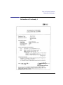
Declaration of Conformity 1 89
Declaration of Conformity 2 90
viii
74
Contents
Special Video Configuration Statements 91
For EN55022 or CISPR 22 Applications:
For FCC Applications: 91
91
Emissions Regulations 92
Federal Communications Commission (FCC)
VCCI Class B ITE (Japan) 93
Korea RRL (EMI Class A) 93
92
Emissions Regulations Compliance 93
Acoustics 94
Regulation On Noise Declaration For Machines -3. GSGV
94
Electrostatic Discharge (ESD) Precautions 94
Safety Statement 95
Laser Safety Statement (U.S.A. Only) 96
Visible LEDs 96
Warnings and Cautions 97
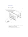
B Changing Your Workstation’s Hardware Configuration
Checking the SCSI IDs 101
Preparing Your Workstation 103
Installing Storage Devices 105
Preparing to Install Your Storage Device 106
Configuring your Storage Device 106
Determining Your Storage Devices Position 106
Storage Device Cable Routing 108
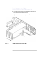
Removing the Storage Tray 108
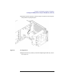
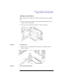
Installing a CD-ROM or a DDS-Format Tape Drive 109
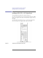
Installing a Floppy Drive 111
ix
Contents
Installing a Hard Disk Drive in Position 1 113
Installing a Hard Disk Drive in Position 3 or Position 4
Replacing the Storage Tray 118
Configuring a Hard Disk Drive 120
115
Removing the Main Tray Assembly 122
Replacing the Main Tray Assembly 124
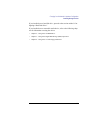
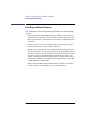
Installing Additional Memory 126
Installing the EGRAM (Enhanced Graphics RAM) Module (C160/C180) 130
Installing an EISA, PCI, or GSC Option Board 136
Graphics Adapter Considerations 137
Special Video Configuration Statements 137
Graphics Paths 138
Graphics Configuration Restrictions 139
Installing the Option Board 141
Replacing the Battery 146
Changing Your Monitor Type 148
Setting the Monitor Type from the Boot Console Interface
Setting the Monitor Type at Power On 148
Changing the Console to External Terminal 149
148
C SCSI Connections
SCSI Bus Differences 153
SCSI Restrictions 156
Cables 156
Connectors and Terminators 158
SCSI Configuration Constraints 159
Narrow, Single-ended SCSI Bus Configuration Constraints 159
Fast, Wide, Differential SCSI Bus Configuration Constraints 160
x
Contents
Ultra, Wide-SE SCSI Bus Configuration Constraints
160
Determining SCSI Bus Length 161
Narrow, Single-Ended SCSI Bus Length 161
Fast, Wide Differential SCSI Bus Length 163
Ultra, Wide, Single-Ended SCSI Bus Length 165
Assigning SCSI Device IDs 167
Narrow Single-Ended SCSI Device IDs 168
Fast, Wide Differential SCSI IDs (C160/C180/C200 Upgrades)
Ultra, Wide SCSI IDs 171
170
Connecting to the SCSI Ports 172
System SCSI Port Connection
172
D The Boot Console Interface
Boot Console Interface Features 177
Accessing the Boot Console Interface 182
Booting Your Workstation 183
Searching for Bootable Media 185
Resetting Your Workstation 186
Displaying and Setting Paths 187
Displaying and Setting the Monitor Type 189
The Monitor Command 189
Displaying the Current Monitor Configuration 190
Setting the Monitor Type 191
Setting the Monitor Type at Power On 193
Changing the Console to External Terminal 194
Displaying the Current Memory Configuration 195
Memory Information Sample 1
196
xi
Contents
Memory Information Sample 2
197
Displaying the Status of the System I/O 198
Setting the Auto Boot and Auto Search Flags 199
Displaying and Setting the Security Mode 201
Displaying and Setting the Fastboot Mode 202
Displaying the LAN Station Address 203
Configure and Display LAN Settings 204
Displaying System Information 206
Displaying PIM Information 207
xii
Preface
This owner’s guide describes how to use your HP 9000 C Class workstation.
This manual assumes that you have installed your workstation as described
in the C Class Hardware Installation Card.
xiii
Audience
This guide is intended for HP 9000 Model C160/C180/C200/C240/C360
workstation users.
Safety and Regulatory Statements
See Appendix A in the back of this manual for safety and regulatory statements that apply to this workstation.
Release Document(s)
Please refer to the Release Document(s) you received with your system or
system software for additional information that we may not have been able
to include in this guide at the time of its publication.
xiv
Related Manuals
Refer to the following manuals for more information:
•
C Class Hardware Installation Card (A4200-90012)
•
Using Your HP Workstation (A2615-90003)
•
Installing and Updating HP-UX (B2355-90050)
•
Configuring HP-UX for Peripherals (B2355-90053)
•
HP Visual User Environment User’s Guide (B1171-90079)
•
Managing Clusters of HP 9000 Computers: Sharing the HP-UX
File System (B2355-90038)
To order manuals, please contact your local sales office.
Revision History
The revision history for each edition of the manual is listed below:
HP Part No.
Edition
Revision History
A4200-90050
E1298
First printing
xv
Documentation Conventions
Unless otherwise noted in the text, this guide uses the following symbolic
conventions.
user-supplied values
Italic words or characters in formats and command descriptions
represent values that you must
supply.
sample user input
In examples, information that the
user enters appears in color.
output
Information that the system displays appears in this typeface.
literal values
Bold words or characters in formats and command descriptions
represent commands or keywords
that you must use literally. Pathnames are also in bold.
KEY
Text with a line above and a line
below denotes a key on your keyboard, or a key or button which is
drawn on your workstation’s
graphic display.
(In this manual we refer to the
Enter key. On your keyboard the
key may be labeled either Enter
or Return.)
xvi
Problems, Questions, and Suggestions
If you have any problems, questions, or suggestions with our hardware, software, or documentation, please call 1-800-633-3600 (US & Canada) or contact the HP Response Center for your country.
xvii
xviii
1
Product Information
1
Product Information
This chapter introduces the HP 9000 Model C160/C180/C200/C240/C360
workstations, including their controls and indicators. This chapter discusses
the following topics:
•
Product description
•
System unit front panel controls
•
System unit rear panel connectors
•
Monitors
•
Keyboards
•
Operating system overview
2
Product Information
Product Description
Product Description
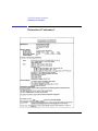
The Model C160/C180/C200/C240/C360 workstations contain the following key features:
•
Processor Performance
160 MHz (Model C160)
180 MHz (Model C180)
200 MHz (Model C200)
236 MHz (Model C240)
367 MHz (Model C360)
•
Operating System: Native HP-UX
HP-UX 10.20 (Model C160)
HP-UX 10.20 (Model C180)
HP-UX 10.20 with Additional Core Enhancements (ACE 9707) (Models
C200/C240)
HP-UX 10.20 with ACE 9806 and IPR 9812 (Model C360)
•
User Interface
HP VUE version 3.0 graphical user interface
HP CDE graphical user interface
•
Compatibility
Source and binary code compatible with the Series 700 product family
•
Optional Graphics
Fast 2D color graphics; choice of 1 to 4 displays
HP VISUALIZE-8/24 - Accelerated 8-plane or 24-plane 3D graphics
HP VISUALIZE-48 - 24/24 image planes, 8 overlay planes,
24-bit Z buffer 3D graphics
HP VISUALIZE-48XP - Advanced, 24/24 image planes, 8 overlay planes,
24-bit Z buffer 3D graphics
HP VISUALIZE-EG, FX2, FX4, FX6 - Advanced graphics
•
Memory
32 MB to 1.5 GB main memory in pairs of 16 MB, 32 MB, 64 MB or
128 MB modules
Six pairs maximum
3
Product Information
Product Description
•
Internal Storage Devices
Fast, Wide Differential SCSI Hard Disk Drives (C160/C180)
or
Ultra, Wide Single-Ended (C200/C240/C360)
1-inch Low Profile Drive (up to two)
1.6-inch Full Height Drive (one)
Single-Ended SCSI Removable Media
CD-ROM Drive
or
2.0/4.0 GB, 4-mm DDS Tape Drive
4/8 GB, DDS2 DAT Drive (C200/C240/C360)
12/24 GB, DDS3 DAT Drive (C200/C240/C360)
3.5-inch Floppy Disk Drive (not a SCSI Device)
•
Standard Network
Ethernet IEEE 802.3 AUI
RJ45, UTP Twisted Pair
10Base-T, 100Base-T (C200/C240/C360 only)
•
Standard I/O
One Single-Ended, 8-bit , 5 MB/sec synchronous, 1.5 MB/sec asynchronous
ALT-1, 50-pin, high density SCSI connector
One Fast, Wide (for hard disk drives) 20 MB/sec synchronous 68-pin, highdensity SCSI connector (C160/C180)
One Ultra, Wide, Single-Ended SCSI connector (C200/C240/C360)
Two Serial Interfaces RS232C, 9-pin male
One Parallel Interface, Centronics, BUSY handshake, 25-pin female
16 Bit Audio Line-in and Line-out connectors
Two PS/2 ports (keyboard and mouse)
One HP-HIL connector (C160/C180 only)
•
EISA/GSC
4 slots total: 1 GSC/PCI, 1 GSC/EISA/PCI and 2 GSC/EISA (C160/180)
4 slots total: 3 GSC/PCI, 1 GSC/EISA/PCI (C200/C240/C360)
•
Keyboards
PS/2 Keyboard (mouse)
or
ITF Keyboard (also known as HP HIL) (HP HIL mouse)(C160/C180 only)
4
Product Information
System Unit Front Panel Controls
System Unit Front Panel Controls
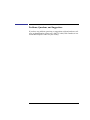
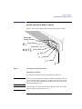
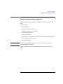
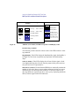
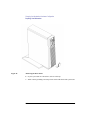
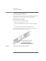
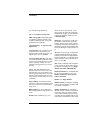
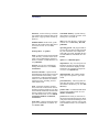
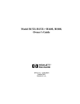
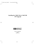
Figure 1 shows the location of the system unit front panel controls.
Removable
Storage Devices
Power Switch
Power LED
System LEDs
Mute
Volume
Headset
Mic
Figure 1
System Unit Front Panel Controls
System Power Switch
Use the power switch to power the system unit on and off.
NOTICE:
There is no need to manually shut down the HP-UX operating system on
your workstation before powering it off. When you turn off the power
switch, your workstation automatically shuts down the operating system
before terminating the power.
NOTICE:
The C200/C240/C360 when turned off and plugged in will draw 30 watts
of power and the cooling fan may turn on.
5
Product Information
System Unit Front Panel Controls
Power LED
The power LED is located on the left side of the front panel on the disk tray.
It lights when the system unit power is on and flashes until the OS is booted.
Once the OS is booted, the LED remains on without flashing, indicating that
a soft shutdown is enabled.
System LEDs
The Model C160/C180/C200/C240/C360 workstations have four diagnostic
LEDs located next to the system power LED.
For more information on the error codes displayed by the diagnostic LEDs,
see “LED Error Codes” in the chapter, “Solving Problems”.
LED 4 - System Heartbeat
LED 3 - SCSI Bus Activity
LED 2 - Network Transmit
LED 1 - Network Receive
6
Product Information
System Unit Front Panel Controls
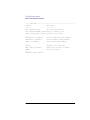
Audio Controls
Next to the system LEDs are the following audio controls:
Headset Jack
Accommodates mini-headphones with a 3.5 mm diameter
miniature stereo plug.
Volume Control
Adjusts the audio output volume
to the headset or lineout.
Mic Jack
Accommodates microphones
with a 3.5 mm diameter miniature stereo plug.
Mute Button
Turns off the audio output to line
out and speaker only.
The volume control, headset jack, and microphone jack features of the CDROM are supported through applications only.
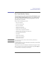
For more information on the features and electrical specifications, see the
section titled “Security Loop,” later in this chapter.
7
Product Information
System Unit Front Panel Controls
Storage Device Controls and Features
The Model C160/C180/C200/C240/C360 workstations allow up to two of
the following internal storage devices: CD-ROM drive, DDS tape drive, or
floppy drive. The following sections describe the controls and features of
these devices.
NOTICES:
You may not have two of the same type of device. For example, you can
have a CD-ROM device and a floppy device, but not two CD-ROMs.
Due to space limitations, a DDS-format tape drive and a CD-ROM drive
cannot both be mounted in the system at the same time.
CD-ROM Drive
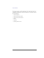
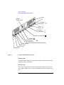
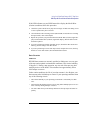
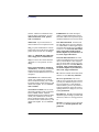
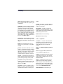
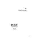
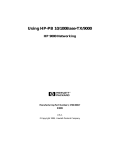
Figure 2 shows the operating controls and features of the CD-ROM drive,
and Table 1 describes them.
Headphone
Jack
Busy
Indicator
Volume
Control
Emergency
Eject
Eject
Button
Disk Tray
Figure 2
CD-ROM Drive Controls and Features
8
Product Information
System Unit Front Panel Controls
Table 1
CD-ROM Drive Controls and Features
Control/Feature
Purpose
Busy Indicator
Lights during a data access operation and blinks during a data
transfer. The indicator blinks
initially and then stays lit when
there is one of the following:
•
A defective disc
•
A disc insertion error (for
example, an upside-down
disc)
•
No disc present
Eject Button
Press to open the disc tray and
insert or remove a disc. When
the drive is in use, press the eject
button for more than one second
to open the disc tray.
Emergency Eject
Remove the Phillips-type screw
and insert the end of a paper clip
to open the disc tray when the
workstation does not have
power.
Disc Tray
Holds the CD-ROM disc. This
type of CD-ROM drive does not
use a disc caddy. The disc tray
does not open if the workstation
power is off.
Headphone Jack
Used to connect headphones
with a 1/8-inch connector.
Volume Control
Volume control for the headphone jack.
9
Product Information
System Unit Front Panel Controls
DDS Tape Drive
Your DDS tape drive is either a DDS-DC (early or later model) or a DDS-2
tape drive with a 3.5-inch form factor, data compression, and a single-ended
SCSI interface. Both drives incorporate data compression capability and are
high-capacity, high transfer-rate devices for data storage on tape. With compression, the DDS-DC drives can store up to 4 GB of data on a 90 meter tape
and the DDS-2 drive can store up to 8 GB of data on a 120 meter tape.
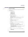
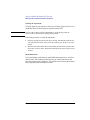
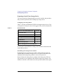
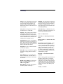
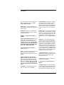
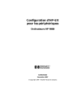
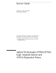
Figure 3, Figure 4, and Figure 5 show the LEDs, and eject button of the
DDS-format tape drives.
Cassette LED
Figure 3
Drive LED
Eject Button
DDS-DC (Early Model) Drive Controls and Indicators
Tape Clean
DCLZ
Tape LED
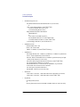
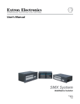
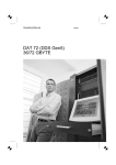
Figure 4
Clean/Attention LED
Eject Button
DDS-DC (Later Model) Drive Controls and Indicators
10
Product Information
System Unit Front Panel Controls
Tape Clean
Tape LED
Figure 5
Table 2
Clean/Attention LED
Eject Button
DDS-2 Drive Controls and Indicators
DDS Tape Drive Controls and Features
Control/Feature
Purpose
Eject Button
Push the eject button to remove tape
cassettes from the drive.
Drive LEDs
The DDS drive LEDs light and flash
to indicate drive status and error conditions.
11
Product Information
System Unit Front Panel Controls
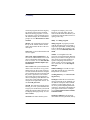
Floppy Disk Drive
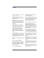
Figure 6 shows the operating controls and features of the floppy drive, and
Table 3 describes them.
Drive LED
Eject Button
Figure 6
Floppy Drive Controls and Features
Table 3
Floppy Drive Controls and Features
Control/Feature
Purpose
Eject Button
Push the eject button to
remove floppy diskettes
from the drive.
Drive LED
The floppy drive LED
flashes to indicate the
drive is in use.
12
Product Information
System Unit Rear Panel Connectors
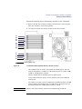
System Unit Rear Panel Connectors
This section describes the following connectors on the system unit’s rear
panel:
NOTICE:
•
Security loop
•
Audio connectors
•
Keyboard and mouse connectors
•
HP parallel (Centronics) I/O connector
•
802.3 network connectors
•
Serial I/O connectors
•
SCSI connectors (including Ultra or Fast, Wide SCSI and single-ended SCSI)
•
TOC (Transfer of Control) button
•
Power cord connector
To maintain emissions compliance, verify that all cables are fully
seated and properly fastened.
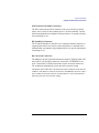
Figure 7 shows the locations of the connectors on the system unit’s rear
panel.
13
Product Information
System Unit Rear Panel Connectors
Power
Monitor
(C180, C200)
TOC
LAN-AUI
LAN-TP
Serial 1
Serial 2
PS/2 Mouse
PS/2 Keyboard
Monitor (C160/C180)
HP Parallel
Single-Ended SCSI
Fast, Wide SCSI
(Ultra Wide Single-Ended C200/C240/C360)
Audio Line Out
Audio Line In
Security Loop
Pullout Card
Figure 7
System Unit Rear Panel Connectors
Pullout Card
The pullout card contains serial and model number information along with
regulatory agency information.
Security Loop
The security loop provides a means of locking the storage tray with a padlock or other locking device, to prevent unauthorized removal from the system.
14
Product Information
System Unit Rear Panel Connectors
Audio Connectors
The Model C160/C180/C200/C240/C360 workstations have audio input and
output capability through external input and output connectors on the rear
panel and through an internal speaker. The rear panel contains the Line IN
(Stereo line-in) and Line OUT (Stereo line-out) connectors.
NOTICE:
To maintain compliance with FCC/CISPR B you must use fully shielded,
unbalanced audio cables and plugs.
The audio connectors are standard stereo audio mini-jacks. Hewlett-Packard
recommends using gold-plated plugs available through audio retailers. The
following summarizes the capabilities of the Model C160/C180/C200/C240/
C360 workstations:
•
Audio Features
Programmable sample rates:
8kHz, 16kHz, 32kHz, 48kHz,
11.025kHz, 22.05kHz, and 44.1kHz.
Programmable output attenuation:
0 to -96dB in -1.5dB steps
Programmable input gain:
0 to 22.5dB in 1.5dB steps.
Input monitoring:
16-bit linear, 8-bit u-law, or A-law coding
•
Audio Inputs
Line-in
Mono microphone compatible with 1.5V phantom supply (bias voltage supplied by the system)
CD-ROM audio (if internal CD-ROM is installed)
•
Audio Outputs
Line-out
Headset
15
Product Information
System Unit Rear Panel Connectors
Built-in mono speaker
•
Audio CODEC
Crystal CS4215
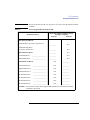
Table 4 summarizes the audio electrical specifications for the Model C160/
C180/C200/C240/C360 workstations.
Table 4
Audio Electrical Specifications
Frequency Response
25-20,000Hz
Input Sensitivity/Impedance
Line Out
2.0Vpk/47k ohm
Microphone
22mVpk/1k ohm
Max Output Level/Impedance
Line Out
2.8Vpp/47k ohm
Headphone
2.75Vpp/50 ohm
Speaker
5.88Vpp/48 ohm
Output Impedance
Line Out
619 ohm
Headphone
118 ohm
Signal to Noise
Line Out
65 dB
Headphone
61 dB
Speaker
63 dB
Line In
61 dB
Microphone
57 dB
THD (w nominal load)
Line Out
-73 dB
Headphone
-70 dB
Speaker
-68 dB
Line In
-75 dB
Microphone
-73 dB
To convert from dB to number of significant bits, use the
formula: n=dB/20 log10 = dB/6. For example, for 61dB
S/N then n=61/6 10 significant bits, or in other words,
about 6 bits of noise.
16
Product Information
System Unit Rear Panel Connectors
PS/2 Keyboard and Mouse Connectors
The PS/2 connectors provide an interface to the system for the keyboard,
mouse, and a variety of other pointing devices, such as trackballs. Consult
the documentation that accompanies each input device for specific information concerning its use.
HP Parallel I/O Connector
The 25-pin HP Parallel I/O interface uses Centronics interface protocols to
support peripheral devices such as printers and plotters. Consult the documentation that accompanies each peripheral device for specific information
concerning its use.
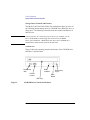
802.3 Network Connectors
The Model C160 and C180 workstations have built-in ThickNet LAN-AUI
and LAN-TP (Twisted Pair) connectors for the 802.3 (ETHERNET) network. Connections to ThinLAN networks require an external transceiver.
The workstation automatically selects the correct network setting.
The Model C200/C240/C360 workstations have built-in ThickNet LAN-AUI and
100Base-T and 10Base-T connectors for the 802.3 (ETHERNET) network. Connections to ThinLAN networks require an external transceiver. The workstation automatically selects the correct network setting.
17
Product Information
System Unit Rear Panel Connectors
Serial Input/Output Connectors
There are a variety of pointing devices (mouse or trackball) or peripheral
devices that can attach to the Serial Input/Output (SIO) ports on the workstation. Peripheral devices include printers, plotters, modems, and scanners.
Consult the documentation that accompanies each peripheral device for specific information concerning its use.
The SIO ports are programmable, allowing functions such as bit rate, character length, parity, and stop bits to be set. The SIO Ports are used as interfaces for serial asynchronous devices to the CPU. The ports operate at up to
a 460.8 K baud rate.
Table 5 shows the SIO connector pin listings. The serial connectors are 9-pin
D-sub connectors. Signal names are those specified in the EIA RS-232 standard.
Table 5
Serial I/O Pins
Pin No.
Signal
Description
1
DCD
Data Carrier Detect
2
RXD
Receive Data
3
TXD
Transmit Data
4
DTR
Data Terminal Ready
5
GND
Ground
6
DSR
Data Set Ready
7
RTS
Request To Send
8
CTS
Clear To Send
9
RI
Ring Indicator
18
Product Information
System Unit Rear Panel Connectors
SCSI Connectors
Use the SCSI connectors to connect external SCSI devices such as DDS-format tape drives and CD-ROM drives. Consult the documentation that
accompanies each SCSI device for specific information concerning its use.
Refer to Appendix C of this manual for information about connecting SCSI
devices to your workstation.
NOTICE:
There must ALWAYS be a terminator at both ends of a SCSI bus. This
means one internal terminator and one external terminator. The Fast-Wide
Differential SCSI, Ultra-wide, Single-Ended SCSI and Narrow SingleEnded SCSI connectors must have a terminator connected when no
external device is connected. Note that the fast, wide differential
terminators, ultra-wide, single-ended terminators and the narrow singleended terminators are different and not interchangeable.
WARNING:
The C200/C240/C360 workstations have an Ultra Wide-SE SCSI interface in
place of the Fast-Wide SCSI interface. These interfaces are not compatible.
Connecting a Fast-Wide device to an Ultra Wide-SE interface will not work and
may damage the device. Be sure to connect only Fast-Wide devices to a FastWide interface and Ultra Wide-SE devices to an Ultra Wide-SE interface.
TOC Button
The TOC button resets the system and transfers control from the default
device to an auxiliary device.
Power Cord Connector
Plug the workstation’s power cord into the power cord connector to provide
ac power to the system.
19
Product Information
Monitors
Monitors
The Model C160/C180 workstations have a graphics controller built-in on
the I/O board. The Model C180/C200/C240/C360 workstations have a highperformance graphics card installed in an option slot. The following HP
monitors are supported:
•
17-inch, 1280x1024 color monitor (A4330)
•
20-inch, 1280x1024 color monitor (A4331)
Before using your monitor you should become familiar with its controls,
connectors, and indicators. For this information, consult the documentation
that was packaged with your monitor.
The built-in monitor connector is a new Enhanced Video connector. An
EVC to DB adapter (HP Part No. 8120-6861), included with your system, is
required to use monitors that have DB-15 type connectors.
20
Product Information
Keyboard
Keyboard
The C160/C180/C200/C240/C360 systems use a PS/2 keyboard which connects to the PS/2 interface connector on the rear of your workstation.
Pointing Devices
The PS/2 connector, the HIL port, or the Serial ports support using an HP
three-button mouse, a trackball, or other options as pointing devices. For
instructions on using a particular device, see the manual that accompanies
the device.
For general information on using three-button mice and on the various cursor shapes associated with different areas of HP VUE while using a mouse,
see Using Your HP Workstation.
21
Product Information
Operating System Overview
Operating System Overview
The Model C160/C180 workstations use version 10.20 or later of the
HP-UX operating system. The Model C200/C240 workstations require the
Workstation Additional Core Enhancements (ACE 9707) for HP-UX 10.20.
The Model C360 workstations require the Workstation Additional Core
Enhancements (ACE 9806) for HP-UX 10.20 and the IPR 9812 software.
Instant Ignition systems (systems with preloaded software) have X-windows
and the Hewlett-Packard HP VUE 3.0 graphical user interface installed and
configured.
Refer to Using Your HP Workstation for more information on Instant Ignition.
22
2
Using Your CD-ROM Drive
23
Using Your CD-ROM Drive
This chapter describes how to use your CD-ROM drive. It is divided into the
following sections:
NOTICE
•
CD-ROM drive and CD-ROM media descriptions
•
Operating the CD-ROM Drive
•
Mounting and unmounting a CD-ROM disc
•
Troubleshooting
Be sure you read and understand the information on mounting and
unmounting CD-ROM discs before you begin using your CD-ROM disc
drive.
This chapter provides an overview of the optional CD-ROM drive and
media, and describes how to use the CD-ROM drive. We assume the CDROM drive is set to the factory default address of SCSI ID 2.
NOTICE
Some procedures in this chapter require you to log in as root. If you cannot
log in as root, contact your system administrator.
24
Using Your CD-ROM Drive
CD-ROM Drive and CD-ROM Media Descriptions
CD-ROM Drive and CD-ROM Media Descriptions
This section describes basic information needed for using the CD-ROM
drive and CD-ROM discs.
CD-ROM Drive
The CD-ROM drive is a random access read-only mass storage device that
uses removable CD-ROM discs. The drive supports the ISO 9660 and High
Sierra format standards. You can access information from the drive like any
other disk drive, except that you cannot write to the drive. The drive contains
a semiconductor laser for reading data optically, and includes an embedded
controller with a SCSI interface.
25
Using Your CD-ROM Drive
CD-ROM Drive and CD-ROM Media Descriptions
Controls and Features
Figure 8 shows and Table 6 describes the operating controls and features of
the CD-ROM drives.
Headset Volume
Jack Control
Thumbwheel
Figure 8
Busy
Indicator
CD-ROM Drive Controls and Features
26
Emergency
Eject Hole
Eject
Button
Using Your CD-ROM Drive
CD-ROM Drive and CD-ROM Media Descriptions
Table 6
CD-ROM Drive Operating Controls and Features
Control/Feature
Purpose
Headset Jack
You can plug mini-headphones with a 3.5-mm diameter
miniature stereo plug into this jack.
Volume Control
Use the volume control to adjust the audio output volume to
the headset jack.
Busy Indicator
The Busy Indicator lights during a data access operation and
blinks during a data transfer. The indicator blinks initially
and then stays lit when there is one of the following:
•
•
•
NOTICE
A defective disc
A disc insertion error (for example, an upside-down disc)
No disc present
Eject Button
Press the Eject Button to open the Disc Tray and insert or
remove a disc. When the drive is in use, you must press the
eject button for more than one second to open the Disc Tray.
Emergency Eject
By inserting the end of a paper clip, you can open the Disc
Tray when the workstation does not have power.
The Volume Control, Headset Jack, and Audio Jack features of the CDROM drive are supported through applications only.
27
Using Your CD-ROM Drive
CD-ROM Drive and CD-ROM Media Descriptions
CD-ROM Media
CD-ROM discs are 120 mm (4.7 in.) in diameter, and use one data surface
with a capacity of approximately 600 megabytes. The data surface contains
pits and flat spots arranged in a continuous spiral track, which is read at a
constant speed. You may access files and data stored on a CD-ROM disc, but
you may not write files or data to a CD-ROM disc.
CD-ROM data discs are identical to audio compact discs (CDs) except that
they store computer data and information.
CAUTION:
Handle CD-ROM discs by the edges only. Always be sure a CD-ROM disc is either
in the CD-ROM drive or its protective case when not in use. This will lessen the
chance of exposing the disc surface to dust. Over time, dust reduces the reliability of
the read head in the CD-ROM drive.
Caring for CD-ROM Discs
Observe the following guidelines to help prevent data loss and prolong the
life of your CD-ROM discs and drive:
NOTICE:
•
Use CD-ROM discs in a clean environment to prevent dust particles from
scratching disc surfaces.
•
Store CD-ROM discs in a cool, dry place to prevent moisture and heat
damage.
•
Don’t try to clean the surface of a CD-ROM disc with cleaning solvents,
as some cleaning solvents may damage the disc.
You must mount the disc after loading it into the drive. Refer to the section
“Mounting and Unmounting a CD-ROM Disc,” later in this chapter, for
instructions about mounting a disc.
28
Using Your CD-ROM Drive
Operating the CD-ROM Drive
Operating the CD-ROM Drive
This section describes how to perform tasks with your CD-ROM drive.
Loading and Unloading a CD-ROM in the Disc Tray
This subsection describes how to load or unload a CD-ROM disc in the CDROM drive.
Disc Tray Description
This CD-ROM is designed to be used in either the horizontal or vertical
position, depending on whether your system unit is horizontal or vertical (in
the floor stand). The disc tray has four spring-loaded disc holders that hold
the disc in place when the CD-ROM drive is in the vertical position. When
the drive is in the horizontal position, the disc holders are not used and are
held out of the way by four disc holder retainers. Figure 9 shows the CDROM disc tray, and disc holders.
Disc
Holder
Disc
Holder
Disc
Holder
Figure 9
CD-ROM Disc Tray
29
Using Your CD-ROM Drive
Operating the CD-ROM Drive
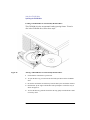
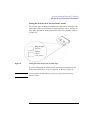
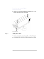
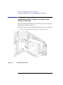
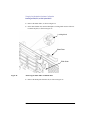
Loading a CD-ROM Disc in a Horizontally Mounted Drive
This CD-ROM drive has an automatic loading/ejecting feature. To load a
disc in the CD-ROM drive, follow these steps:
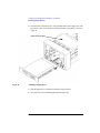
Figure 10
Placing a CD-ROM Disc in a Horizontally Mounted Drive
1
Check that the workstation is powered on.
2
To open the disc tray, press and release the load/eject button on the CD-ROM
drive.
3
Be sure the disc holders are held away from the disc by the disc holder retainers.
4
Hold the disc by the edges with the label side up and place it in the disc tray as
shown in Figure 10.
5
To close the disc tray, push the front of the disc tray gently towards the drive until
it closes by itself.
30
Using Your CD-ROM Drive
Operating the CD-ROM Drive
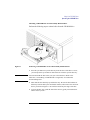
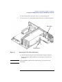
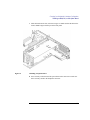
Unloading a CD-ROM Disc in a Horizontally Mounted Drive
Perform the following steps to unload a disc from the CD-ROM drive:
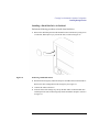
Figure 11
Removing a CD-ROM Disc From a Horizontally Mounted Drive
1
NOTICE:
Press the eject button to eject the disc tray from the drive. If the drive is in use,
you must press the eject button for more than one second to eject the disc tray.
You must unmount the disc before you eject it from the drive. Refer to the
subsection, “Unmounting a CD-ROM Disc Using SAM,” for instructions
on unmounting a disc.
2
Wait until the drive has fully ejected the disc tray. Be sure the disc holders are
held away from the disc by the disc holder retainers, Then remove the disc from
the tray as shown in Figure 11. Be careful to touch only the edges of the disc.
3
To close the Disc Tray, push the front of the disc tray gently towards the drive
until it closes by itself.
31
Using Your CD-ROM Drive
Operating the CD-ROM Drive
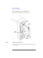
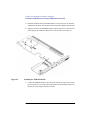
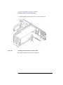
Loading a CD-ROM Disc in a Vertically Mounted Drive
To load a disc in the CD-ROM drive, follow these steps:
Disc
Holder D
Disc
Holder C
Disc
Holder A
Disc
Holder B
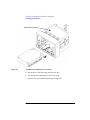
Figure 12
Releasing the Disc Holder Retainers
1
32
Make sure the four disc holders are disengaged from the disc holder retainers, as
shown in Figure 12.
Using Your CD-ROM Drive
Operating the CD-ROM Drive
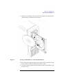
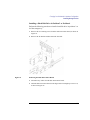
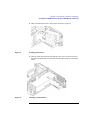
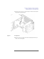
2
Figure 13
Hold the disc with the label side away from the tray and place the edge of the disc
onto disc holders A and B as shown in Figure 13.
Placing a CD-ROM Disc in a Vertically Mounted Drive
3
Press down gently against the spring tension of disc holders A and B, and swing
the top of the disc in until it is held by disc holders C and D.
4
To close the disc tray, push the front of the disc tray gently towards the drive until
it closes by itself.
33
Using Your CD-ROM Drive
Operating the CD-ROM Drive
Unloading a CD-ROM Disc in a Vertically Mounted Drive
Perform the following steps to unload a disc from the CD-ROM drive:
Figure 14
Removing a CD-ROM Disc From a Vertically Mounted Drive
1
NOTICE:
Press the eject button to eject the disc tray from the drive. If the drive is in use,
you must press the eject button for more than one second to eject the disc tray.
You must unmount the disc before you eject it from the drive. Refer to the
subsection, “Unmounting a CD-ROM Disc Using SAM,” for instruction on
unmounting a disc.
2
Press down gently against the spring tension of disc holders A and B and swing
the top of the disc away from disc holders C and D as shown in Figure 14.
3
Remove the disc from disc holders A and B.
4
To close the Disc Tray, push the front of the disc tray gently towards the drive
until it closes by itself.
34
Using Your CD-ROM Drive
Operating the CD-ROM Drive
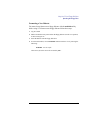
Verifying the CD-ROM Drive Operation
To verify that your workstation can communicate with the CD-ROM drive,
follow these steps:
1
In a terminal window, enter the following command:
/usr/sbin/ioscan -d sdisk RETURN
After a few moments the ioscan utility lists all of the SCSI I/O devices it could
find. The list appears similar to the following:
H/W Path
Class
Description
============================================
bc
8
bc
8/12
ext_bus
8/12.0
target
8/12.0.0
disk
8/12.5
target
8/12.5.0
disk
8/12.6
target
8/12.6.0
disk
I/O Adapter
GSC built-in Fast/Wide SCSI Interface
QUANTUM LPS1080WD
DEC
DSP3210SW
DEC
DSP3210SW
8/16
ba
Core I/O Adapter
8/16/5
ext_bus
Built-in SCSI
8/16/5.2
target
8/16/5.2.0
disk
8/16/5.4
target
8/16/5.4.0
disk
8/16/5.6
target
8/16/5.6.0
disk
MICROP
10
bc
I/O Adapter
10/12
ext_bus
GSC add-on Fast/Wide SCSI Interface
10/12.4
target
10/12.4.0
disk
TOSHIBA CD-ROM XM-4101TA
SEAGATE ST3600N
2112
SEAGATE ST31200W
If ioscan does not see your CD-ROM drive it returns the following message:
ioscan: No hardware found
If you receive this message, go to Chapter 6, “Solving Problems.”
35
Using Your CD-ROM Drive
Mounting and Unmounting a CD-ROM Disc
Mounting and Unmounting a CD-ROM Disc
To access information on a CD-ROM disc, you must first mount the disc.
This applies to file system information only. If you wish to load a music CD,
for example, you would not need to mount the disc. Mounting a disc with
file system information on it gives the disc a pathname that allows your
workstation to communicate electronically with it. You must unmount the
CD-ROM disc before removing it from the drive.
CAUTION:
To use a CD-ROM disc as a mounted file system, you must mount the CD-ROM disc
every time you load it into the drive. You must also unmount the CD-ROM disc
every time you unload it from the drive. Failure to mount or unmount a disc can cause
a system error condition that can require rebooting the system.
If your workstation is running HP VUE, follow these instructions to mount
and unmount a CD-ROM disc as a file system. If you’re using something
other than HP VUE, use the instructions for mounting and unmounting a
CD-ROM disc that come with that product. For more information on configuring your CD-ROM drive, see the System Administration Tasks manual or
online help.
The procedures in this chapter require you to log in as root. If you cannot
log in as root, contact your system administrator.
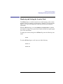
Mounting a CD-ROM Disc Using SAM
Use the following procedure to mount a CD-ROM disc:
1
Log in as root. If you need information on logging in or setting up a user
account, see Using Your HP Workstation.
2
Load the CD-ROM disc into the disc tray and gently push the tray into the
drive.
3
In a terminal window, enter the following command:
sam RETURN
36
Using Your CD-ROM Drive
Mounting and Unmounting a CD-ROM Disc
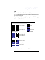
4
The System Administration Manager window opens. Double-click on
Peripheral Devices ->.
5
The Peripheral Devices window opens. Double-click on Disks and File
Systems ->.
6
The Disks and File Systems window opens. Double-click on CD-ROM,
Floppy, and Hard Disks.
The following screen message appears:
Scanning the system’s hardware...
The CD-ROM, Floppy, and Hard Disks window opens containing a list of
drives currently configured on this system. Disks that are unmounted will have
the word “unused” in the Use column.
7
From the Actions menu, click on Add a Hard Disk Drive
8
The Select a Disk to Add... window opens with a list of unused disks. Highlight
the CD-ROM disc you want to mount.
9 Click on OK.
10 The Set Disk Usage and Options... window opens. Select File System
and click on OK.
11 The following screen messages appear:
Task started.
Creating the device file...
Mounting file system...
Modifying “/etc/checklist”...
Task completed.
Click on OK.
Now you can access the CD-ROM disc as you would any other mounted file
system.
37
Using Your CD-ROM Drive
Mounting and Unmounting a CD-ROM Disc
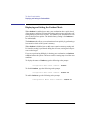
Unmounting a CD-ROM Disc Using SAM
Use the following procedure to unmount a CD-ROM disc:
NOTICE:
Before you unmount a CD-ROM disc, make sure that your working
directory (the directory in which a relative path name search begins)
is set to some directory other than the one under which the disc was
mounted.
CAUTION:
If you wish to use a CD-ROM disc as a mounted file system, you must mount
the CD-ROM disc every time you load it into the drive. You must also
unmount the CD-ROM disc every time you unload it from the drive. Failure
to mount or unmount a disc may cause a system error condition that may
require rebooting the system.
1
Log in as root. If you need information on logging in or setting up a user
account, see Using Your HP Workstation.
2
In a terminal window, enter the following command:
sam RETURN
3
The System Administration Manager window opens. Double-click on
Peripheral Devices ->.
4
The Peripheral Devices window opens. Double-click on Disks and File
Systems ->.
5
The Disks and File Systems window opens. Double-click on CD-ROM,
Floppy, and Hard Disks.
The following screen message appears:
Scanning the system’s hardware...
The CD-ROM, Floppy, and Hard Disks window opens containing a list of
drives currently configured on this system.
6
38
Highlight the disc you want to unmount and click on Remove a Hard
Disk Drive from the Actions menu.
Using Your CD-ROM Drive
Mounting and Unmounting a CD-ROM Disc
7
A window with the following message opens:
Do you want to remove the disk?
Click on Yes.
8
Press the eject button on the CD-ROM drive and remove the CD-ROM
disc from the disc tray.
Reading the Busy Light
The CD-ROM busy light shows the status of the drive during the self test
and during activity with the host system.
The CD-ROM drive performs the self test when one of the following happens:
•
You load a disc and close the Disc Tray.
•
You turn on the workstation with a disc already loaded in the CD-ROM
drive.
For the self test, the busy light operates in the following sequence:
1
Light On - The busy light goes on when the disc loads into the
drive.
2
Light Flashing - The light flashes six times while a read test is performed on the disc.
3
Light Off - The light goes off when the self test is complete.
39
Using Your CD-ROM Drive
Mounting and Unmounting a CD-ROM Disc
The busy light stays on after the self test when one of the following conditions exist:
•
A defective disc
•
A disc insertion error (for example, an upside-down disc)
•
No disc present
The busy light goes off when one of the following conditions exist:
•
A CD-ROM drive power failure exists.
•
The drive is idle on the SCSI bus.
The busy light flashes during normal activity with the system.
40
Using Your CD-ROM Drive
Troubleshooting
Troubleshooting
If you have trouble with any of these procedures for using your CD-ROM
drive, see Chapter 5 of this book, “Solving Problems.”
41
Using Your CD-ROM Drive
Troubleshooting
42
3
Using Your Digital Data Storage (DDS)
Tape Drive
43
Using Your Digital Data Storage (DDS) Tape Drive
This chapter describes how to use the optional Digital Data Storage (DDS)
tape drive. It also describes how to maintain and care for the drive.
This chapter provides information on the following:
CAUTION:
•
DDS tape drive and data cassette descriptions
•
Operating the DDS tape drive
•
Ordering information
Use only data cassettes labeled DDS (Digital Data Storage). Never use audio
cassettes labeled DAT (Digital Audio Tape) in your DDS-format drive.
44
Using Your Digital Data Storage (DDS) Tape Drive
DDS Tape Drive and Data Cassette Descriptions
DDS Tape Drive and Data Cassette Descriptions
This section describes basic information needed for using your DDS tape
drive and data cassettes.
DDS Drive
Your DDS tape drive is either a DDS-DC (early or later model) or a DDS-2
tape drive with a 3.5-inch form factor, data compression, and a narrow single-ended SCSI interface. Both drives incorporate data compression capability and are high-capacity, high transfer-rate devices for data storage on tape.
With compression, the DDS-DC drives can store up to 4 GB of data on a 90
meter tape and the DDS-2 drive can store up to 8 GB of data on a 120 meter
tape.
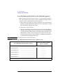
Storage Capacities
The maximum storage capacities of different DDS drives with and without
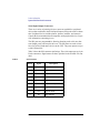
data compression are shown in the following tables;
Table 7
Table 8
DDS Tape Drive Capacities Without Data Compression
Tape Length
Full Height 5 1/4
DDS Tape Drive
DDS-DC
Tape Drives
DDS-2
Tape Drive
60 meter
1.3 GB
1.3 GB
1.3 GB
90 meter
Not Supported
2.0 GB
2.0 GB
120 meter
Not Supported
Not Supported
4.0 GB
DDS Tape Drive Capacities With Data Compression
Tape Length
Full Height 5 1/4
DDS Tape Drive
DDS-DC
Tape Drives
DDS-2
Tape Drive
60 meter
2.6 GB
2.6 GB
2.6 GB
90 meter
Not Supported
4.0 GB
4.0 GB
120 meter
Not Supported
Not Supported
8.0 GB
45
Using Your Digital Data Storage (DDS) Tape Drive
DDS Tape Drive and Data Cassette Descriptions
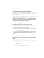
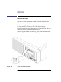
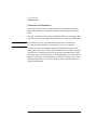
Controls and Indicators
Figure 15, Figure 16, and Figure 17 show the LEDs, and eject button of the
DDS-format tape drives.
Cassette LED
Figure 15
Drive LED
Eject Button
DDS-DC (Early Model) Drive Controls and Indicators
Tape Clean
DCLZ
Tape LED
Figure 16
Clean/Attention LED
Eject Button
DDS-DC (Later Model) Drive Controls and Indicators
Tape Clean
Tape LED
Figure 17
Clean/Attention LED
DDS-2 Drive Controls and Indicators
46
Eject Button
Using Your Digital Data Storage (DDS) Tape Drive
DDS Tape Drive and Data Cassette Descriptions
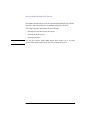
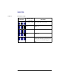
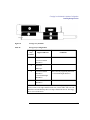
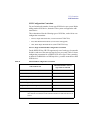
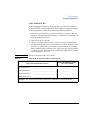
LEDs
This section describes the LED codes that are displayed.
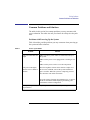
The two LEDs on the front panels of the DDS drives indicate different activities or problems that occur.
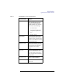
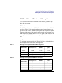
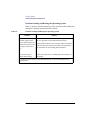
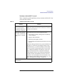
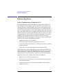
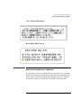
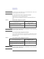
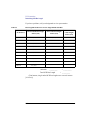
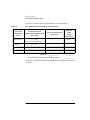
Figure 18 lists the LED codes and their meanings for the DDS-DC early
model drive. Figure 19 lists the LED codes and their meanings for the DDSDC later model and DDS-2 drives.
Cassette
Drive
Meaning
Key
OFF
Read/Write States
Cassette (un)loading
Green
Cassette loaded/online
Amber
Cassette loaded/activity
Pulsing Green
Cassette loaded/offline
Pulsing Amber
Pulsing Green
and Amber
Write-Protect States
Cassette (un)loading
Cassette loaded/online
Cassette loaded/activity
Cassette loaded/offline
Error States
Media wear (caution)
High humidity
Self-test (normal)
Self-test (failure)
Figure 18
DDS-DC (Early Model) Tape Drive LED Display Codes
47
Using Your Digital Data Storage (DDS) Tape Drive
DDS Tape Drive and Data Cassette Descriptions
Tape
Clean/
Attention
Meaning
Key
OFF
Activity — load or unload
Steady Green
Steady Amber
Activity — read or write
Flashing Green
Cartridge loaded
Figure 19
Any
Cleaning needed
Any
Fault
1/2 sec on, 1/2 sec off
Pulsing Amber
Fast Flash Green
1/4 sec on 1/4 sec off
DDS-DC (Later Model) and DDS-2 Tape Drive LED Display Codes
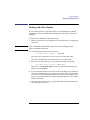
LED Warning Conditions
The following sections describe actions to take if the LEDs indicate a warning condition.
High Humidity If the LEDs display the high humidity signal, the humidity is
too high. The drive does not perform any operations until the humidity
drops.
Self-Test (Failure) If the LEDs display the self-test (failure) signal, a fault
was diagnosed during the self tests. Note the pattern of the pulses and contact your local service representative.
Media Wear (Caution) Hewlett-Packard DDS drives continually monitor the
number of errors they have to correct when reading and writing to a tape to
determine tape wear and tape head cleanliness. If excessive tape wear or
dirty tape heads are suspected, the drive warns you by displaying the Media
Wear (Caution) signal on the LED indicators.
48
Using Your Digital Data Storage (DDS) Tape Drive
DDS Tape Drive and Data Cassette Descriptions
If the LED indicators on your DDS-format drive display the Media Wear
(Caution) condition, follow this procedure:
1
Check the system console for any tape error messages. A hard error during a read
or write operation may have occurred.
2
Clean the heads with a cleaning cassette (HP92283K) as described in “Cleaning
the Tape Heads,” later in this chapter.
3
Repeat the operation you performed when the Media Wear (Caution) signal displayed. If the Media Wear (Caution) signal still displays, then the data cassette
should be replaced.
4
If you are performing a backup from disk to tape, discard the data cassette and
back up your files using a new data cassette.
5
If you are performing a restore from tape to disk, complete the restore, back up
the files to a new data cassette, then discard the data cassette.
Data Cassettes
Media Life
HP DDS data cassettes are currently specified to 2000 passes over any part
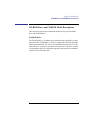
of the tape under optimal environmental conditions (50% relative humidity,
22 degrees C). During a tape operation, any one area of the tape may have
multiple passes over the heads. This translates into approximately 200 to
300 backups or restores.
Under certain conditions, the life of your data cassette is less. Replace your
data cassettes after 100 backups or restores if your operating conditions meet
any of the following criteria:
•
The relative humidity in your operating environment is consistently less than
50%.
•
You know that the backup software you are using makes multiple passes over sections of the tape during backups or restores.
•
You notice that when you do backups and restores the tape stops and starts frequently.
49
Using Your Digital Data Storage (DDS) Tape Drive
DDS Tape Drive and Data Cassette Descriptions
Cleaning the Tape Heads
Clean the heads of your tape drive after every 25 hours of tape drive use or if
the Media Wear (Caution) signal is displayed on the LED.
NOTICE:
Only use HP Cleaning Cassettes (HP92283K) to clean the tape heads. Do
not use swabs or other means of cleaning the tape heads.
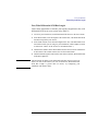
Follow this procedure to clean the tape heads:
1
Insert the cleaning cassette into the drive. The tape automatically loads the cassette and cleans the heads. At the end of the cleaning cycle, the drive ejects the
cassette.
2
Write the current date on the label on the cleaning cassette so that you know how
many times you have used it. Discard the cleaning cassette after you have used it
25 times.
Media Restrictions
If you interchange media between other DDS-format tape drives, note that
data cassettes with compressed data can only be read by tape drives that
have data compression capabilities. This includes data cassettes that contain
both compressed and noncompressed data.
50
Using Your Digital Data Storage (DDS) Tape Drive
DDS Tape Drive and Data Cassette Descriptions
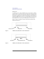
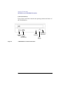
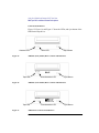
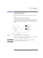
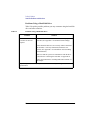
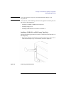
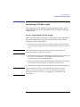
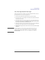
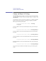
Setting the Write-Protect Tab on a Data Cassette
You can only store or change information on a data cassette when the writeprotect tab is in the write position. So, before trying to write to the data cassette, make sure that the write-protect tab is in the write position, as shown
in Figure 20.
Push tab right
for write.
Push tab
left for
write-protect.
Figure 20
Setting the Write-Protect Tab on a DDS Tape
To protect information on a data cassette from being overwritten, set the
write-protect tab to the write-protect position, as shown in Figure 20.
NOTICE:
The write-protect tab should always be in the write position for transferring
data to a cassette.
51
Using Your Digital Data Storage (DDS) Tape Drive
Operating the DDS Tape Drive
Operating the DDS Tape Drive
This section describes how to perform tasks with your DDS tape drive.
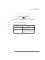
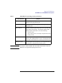
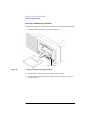
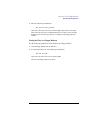
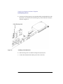
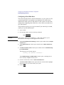
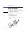
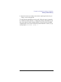
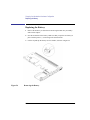
Loading and Unloading a Data Cassette
Follow these steps to load and unload a data cassette from the DDS tape
drive:
1
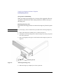
Insert the data cassette into the drive, as shown in Figure 21.
Eject Button
Figure 21
Loading and Unloading a Data Cassette
2
Push the data cassette about three quarters of the way into the drive. The drive
automatically pulls the data cassette the rest of the way in. When the LEDs on the
front of the drive stop flashing, the drive has loaded the data cassette.
3
To remove the data cassette, press and release the eject button on the front of the
drive, as shown in Figure 21. The LEDs on the drive flash on and off. Ten to twenty seconds later, the data cassette slides partway out of the drive. Remove the cassette from the drive.
52
Using Your Digital Data Storage (DDS) Tape Drive
Operating the DDS Tape Drive
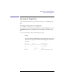
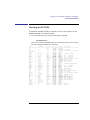
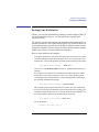
Verifying the DDS Tape Drive Operation
To verify that your workstation can communicate with the DDS-format tape
drive, enter the following:
/usr/sbin/ioscan -d stape
After a few moments the ioscan utility returns a message similar to the following:
H/W Path
Class
Description
============================================
bc
8
bc
I/O Adapter
8/16
ba
Core I/O Adapter
8/16/5
ext_bus
Built-in SCSI
8/16/5.3
target
8/16/5.3.0
tape
HP
HP35480A
If ioscan does not see your tape drive, it will return the following message:
ioscan: No hardware found
If you receive this message, go to Chapter 5, “Solving Problems.”
53
Using Your Digital Data Storage (DDS) Tape Drive
Operating the DDS Tape Drive
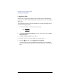
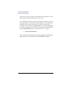
Using Device Files
Device files are special files that tell your system which system hardware
pathway to use when communicating with a specific device, and what kind
of device it is.
To determine what device files are available for use with your tape drive, use
the following procedure:
1
In a terminal window, enter the following command:
sam RETURN
2
The System Administration Manager window opens. Double-click on Peripheral Devices ->.
3
The Peripheral Devices window opens. Double-click on Tape Drives ->.
4
The Tape Drives window opens.
5
In the list of tape drives, click on the desired tape drive to select it.
6
From the Actions menu, click on Show Device Files.
A window opens with a list of the device files for the selected tape drive with an
explanation of each one.
54
Using Your Digital Data Storage (DDS) Tape Drive
Operating the DDS Tape Drive
Archiving Data
This section describes how to transfer data to and from a DDS-format data
cassette (saving and restoring) using the HP-UX tar command and your tape
drive’s device file.
The tar command allows you to save files to a data cassette, restore files
from a data cassette to your system, or list the files on your data cassette.
Writing to a Data Cassette
Use the following instructions to save files to a data cassette:
1
Check that the write-protect tab on the data cassette is in the write position.
2
Load the data cassette into the tape drive.
3
In a terminal window, enter the following command line to write to the tape:
tar -cvf /dev/rmt/devicefile pathname
where devicefile is one of the device files listed from sam and pathname is the
pathname of the file or directory containing files that you want to write to the
tape. To use the data compression mode, use one of the device file names that
sam listed as supporting compression.
55
Using Your Digital Data Storage (DDS) Tape Drive
Operating the DDS Tape Drive
Restoring Files from a Data Cassette to Your System
Use the following instructions to restore files from a data cassette to your
system:
1
Load the data cassette into the tape drive.
2
In a terminal window, use cd to change to the directory you want the files to reside
in.
3
Enter the following command line to restore data:
tar -xvf /dev/rmt/devicefile pathname
where devicefile is one of the device files listed from sam and pathname is the
pathname of the file or directory containing files that you want to restore from
the tape. If pathname is not specified, everything on the data cassette is restored.
If the tape was made using data compression, use one of the device file names
that sam listed as supporting compression.
Listing the Files on a Data Cassette
Use the following instructions to list the files on a data cassette:
1
Load the data cassette into the tape drive.
2
In a terminal window, enter the following command line to receive a file listing
of the data cassette:
tar -tvf /dev/rmt/devicefile
where devicefile is one of the device files listed from sam. If the tape was made
with data compression, use one of the device file names that sam listed as supporting compression.
56
Using Your Digital Data Storage (DDS) Tape Drive
Operating the DDS Tape Drive
Further Command Information
For additional information on using tar and a complete list of the command
arguments, refer to the tar man page by typing the following:
man tar
The man utility looks up man pages on the system.
You may also communicate with the tape drive with the cpio, ftio, mt, and
fbackup commands. For more information on these commands, enter the
following in a terminal window:
man command
57
Using Your Digital Data Storage (DDS) Tape Drive
Troubleshooting
Troubleshooting
If you have trouble with any of these procedures for using your DDS tape
drive, see Chapter 5 of this book, “Solving Problems.”
Ordering Information
To order Hewlett-Packard data cassettes and cleaning cassettes for use in
your DDS tape drive, use the following order numbers:
CAUTION:
•
HP92283A - Box of five 60-meter DDS data cassettes
•
HP92283B - Box of five 90-meter DDS data cassettes
•
HP92300A - Box of five 120-meter DDS data cassettes
(not supported on the DDS-DC drives)
•
HP92283K - Package of two head-cleaning cassettes
•
HP92283L - Lockable storage box for 12 cassettes
Use only data cassettes labeled as DDS (Digital Data Storage) cassettes. Never use
audio cassettes labeled DAT (Digital Audio Tape) in your DDS-format drive.
58
4
Using Your 3.5-Inch Floppy Disk Drive
59
Using Your 3.5-Inch Floppy Disk Drive
This chapter describes how to perform tasks that allow you to archive to or
transfer data from the optional 3.5-inch floppy disk drive. The information is
organized into the following sections:
NOTICE:
•
Using the floppy diskette
•
Operating the floppy drive
•
Ordering information
Some procedures in this chapter require you to log in as root. If you cannot
log in as root, contact your system administrator.
60
Using Your 3.5-Inch Floppy Disk Drive
Using the Floppy Diskette
Using the Floppy Diskette
This section describes basic information needed for using your floppy diskettes.
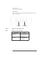
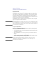
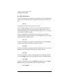
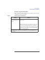
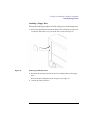
Setting the Write-Protect Tab on a Diskette
You can only store or change information on a diskette when the write-protect tab is in the write position. So, before trying to write to the diskette,
make sure that the write-protect tab is in the write position, as shown in Figure 22.
Push tab up
for write.
Push tab
down for
write-protect.
Figure 22
Setting the Write-Protect Tab on a Floppy Diskette
To protect files on a diskette from being overwritten, set the write-protect tab
to the write-protect position, as shown in Figure 22.
NOTICE:
The write-protect tab should always be in the write position for formatting
a new diskette and transferring data to a diskette.
61
Using Your 3.5-Inch Floppy Disk Drive
Using the Floppy Diskette
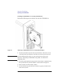
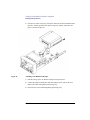
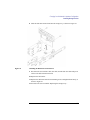
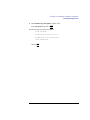
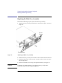
Inserting and Removing a Diskette
Follow these steps to insert and remove a diskette from the floppy disk drive:
1
Insert the diskette into the drive, as shown in Figure 23.
Eject Button
Figure 23
Inserting and Removing a Floppy Diskette
2
Push the diskette into the floppy drive until it clicks into place.
3
To remove the diskette, push the eject button, as shown in Figure 23. Then remove the diskette.
62
Using Your 3.5-Inch Floppy Disk Drive
Operating the Floppy Drive
Operating the Floppy Drive
This section describes how to perform tasks with your 3.5-inch floppy disk
drive.
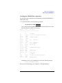
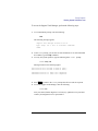
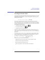
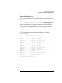
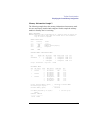
Verifying the Floppy Drive Configuration
To verify that your workstation can communicate with the floppy drive, use
the ioscan command to see which devices are currently in use on your system.
1
In a terminal window, enter the following at the prompt:
ioscan
After a few moments the ioscan utility lists all of the I/O devices it could
find. If there is a floppy drive in the list, that listing appears similar to the
following:
H/W Path
Class
Description
============================================
8
bc
I/O Adapter
8/0
graphics
Graphics
8/16/10
pc
Built-in Floppy Drive
63
Using Your 3.5-Inch Floppy Disk Drive
Operating the Floppy Drive
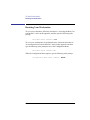
Using Device Files
Device files are special files that tell your system which system hardware
pathway to use when communicating with a specific device and what kind of
device it is.
To determine what device files are available for use with your floppy drive,
use the following procedure:
1
In a terminal window, enter the following command:
sam RETURN
2
The System Administration Manager window opens. Double-click on Disks
and File Systems->.
3
The Disks and File Systems window opens.
4
In the list of drives, click on the floppy drive listing to select it.
5
From the Actions menu, click on View More Information.
A window opens with a list of information for the floppy drive, including the
device files. Identify your floppy device file number and use it in the following
steps.
64
Using Your 3.5-Inch Floppy Disk Drive
Operating the Floppy Drive
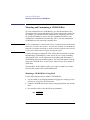
Formatting a New Diskette
You must always format a new floppy diskette with the mediainit utility
before using it. To format a new floppy diskette follow these steps:
1
Log in as root.
2
Make sure that the write-protect tab on the floppy diskette is in the write position,
as shown in Figure 22.
3
Insert the diskette into the floppy disk drive.
4
In a terminal window, execute mediainit with an interleave of 2 by entering the
following:
mediainit -i 2 devicefile
where devicefile is the device file as listed by sam .
65
Using Your 3.5-Inch Floppy Disk Drive
Operating the Floppy Drive
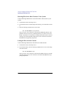
Transferring Data To and From a Floppy Diskette
This section describes how to transfer data to and from your floppy diskette
(saving and restoring) using the HP-UX tar command with your floppy
drive’s device file.
The tar command saves files to a floppy diskette, restores files from a floppy
diskette, or lists files on a floppy diskette.
You need to set the write protect tab to the write position to transfer data to
the diskette. The write-protect tab can be in either position when restoring
data from a diskette or listing the files on a diskette.
Saving Files to a Floppy Diskette
Use the following instructions to save files to a floppy diskette:
1
Check that the write-protect tab on the floppy diskette is in the write position.
2
Load the formatted floppy diskette into the disk drive.
3
In a terminal window, enter the following command line to write to the diskette:
tar -cvf devicefile pathname
where devicefile is the device file as listed by sam and pathname is the pathname of the file or directory containing files that you want to write to the diskette.
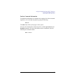
Restoring Files from a Floppy Diskette to Your System
Use the following instructions to restore files from a floppy diskette to your
system:
1
Load the floppy diskette into the disk drive.
2
In a terminal window, use the cd command to change to the directory you want
the files to reside in:
cd directory_path
where directory_path is the pathname of the directory.
66
Using Your 3.5-Inch Floppy Disk Drive
Operating the Floppy Drive
3
Enter the following command line:
tar -xvf devicefile pathname
where devicefile is the device file as listed by sam and pathname is the pathname of the file or directory containing files that you want to restore from the
diskette. If you don’t specify pathname, everything on the floppy diskette is
restored.
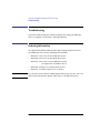
Listing the Files on a Floppy Diskette
Use the following instructions to list the files on a floppy diskette:
1
Load the floppy diskette into the disk drive.
2
In a terminal window, enter the following command line:
tar -tvf devicefile
where devicefile is the device file as listed by sam.
All files on the floppy diskette are listed.
67
Using Your 3.5-Inch Floppy Disk Drive
Operating the Floppy Drive
For More Information
For more information on using tar and a complete list of the command arguments, refer to the tar man page by typing the following in a terminal window:
man tar
The man utility looks up man pages on the system.
You can mount the floppy drive as a file system using the SAM utility. Be
sure to unmount the drive before removing it as a file system. For more
information about how to mount and unmount the floppy drive, see the manual Using HP-UX (B2910-90001).
For more information on copying data to or from your system to other
media, including your floppy diskette, refer to the cpio man page by typing
the following in a terminal window:
man cpio
For more information on copying to or from DOS files, refer to the doscp
man page by typing the following in a terminal window:
man doscp
For more information on listing the contents of DOS directories, refer to the
dosls man page by typing the following in a terminal window:
man dosls
For more information on using your floppy disk drive and floppy diskettes,
refer to the floppy man page by typing the following in a terminal window:
man floppy
For more information on using the mediainit command, refer to the mediainit man page by typing the following in a terminal window:
man mediainit
68
Using Your 3.5-Inch Floppy Disk Drive
Operating the Floppy Drive
Configuring the Floppy Driver
If you reload software or rebuild the Instant Ignition system on your workstation, you need to reconfigure the HP-UX Kernel to add the floppy driver.
Use the SAM utility to add the flexible disk driver and build a new HP-UX
kernel.
For more information about how to reconfigure the kernel using SAM, see
the following manuals:
•
System Administration Tasks HP 9000 Series 700 Computers (B2355-90040)
•
Using HP-UX (B2910-90001)
69
Using Your 3.5-Inch Floppy Disk Drive
Troubleshooting
Troubleshooting
If you have trouble with any of these procedures for using your floppy disk
drive, see Chapter 5 of this book, “Solving Problems.”
Ordering Information
To order Hewlett-Packard micro flexible diskettes for use in your 3.5-inch
floppy disk drive, use the following order number:
HP-92192X
70
High-Density Micro Flexible Disks
(1.44MB Formatted Capacity) - box of ten diskettes
5
Solving Problems
71
Solving Problems
This chapter contains information to help you determine what’s wrong with
your system when you have problems. If you have a problem that isn’t listed
in this chapter, or if your problem persists, contact your designated service
representative. When calling for service, always have your system’s model
number and serial number ready.
This chapter is divided into the following sections
•
Common problems and solutions
•
Interpreting LED error codes
•
Dealing with a boot failure
•
Running system verification tests
72
Solving Problems
Common Problems and Solutions
Common Problems and Solutions
The tables in this section list common problems you may encounter with
your workstation. The tables also tell you what to do to help solve the problems.
Problems with Powering Up the System
Table 9 describes possible problems you may encounter when powering up
the system and offers solutions.
Table 9
Power -up Problems
Problem
The power LED does not
light.
Solution
Make sure all AC power cables are connected securely to
the system.
Make sure the power cord is plugged into a working ac outlet.
Make sure the power switch is set to the ON position.
The power LED lights,
but the screen is blank or
flickers.
Press the brightness control on the monitor to adjust it. If
the screen is still blank, turn off the system and monitor
power switches. When the system is completely powered
off, check the video cable connections.
Go to the section “Changing Your Monitor Type” in Appendix B for information about displaying and setting your
workstation’s monitor configuration.
If the problem persists, contact your system administrator or call your designated service
representative.
73
Solving Problems
Common Problems and Solutions
Problems Loading and Booting the Operating System
Table 10 describes possible problems you may encounter when loading and
booting the operating system and offers solutions.
Table 10
Problems Loading and Booting the Operating System
Problem
Solution
The power LED is lit,
and text appears on the
screen, but more than two
minutes have passed with
no sign of system activity.
Make sure that all SCSI devices are set to the proper SCSI
ID. (See Appendix C for default SCSI ID settings.)
The system stops or
hangs while booting.
Follow the instructions in “Dealing With a Boot Failure” in
this chapter.
Check that all SCSI devices are correctly cabled. Check that
both SCSI buses are correctly terminated. (See Appendix C
for information on SCSI cabling and termination.)
If problem persists, contact your system administrator or call your designated service
representative.
74
Solving Problems
Common Problems and Solutions
Problems with the 802.3 Network
Table 11 describes possible problems you may encounter with the 802.3 network and offers solutions.
Table 11
Problems with the 802.3 Network
Problem
Solution
Cannot reach other systems on the network.
Applications that rely on
the network will not run.
Check the network connector on the back of the system unit.
Make sure that the network cable or transceiver is fastened
securely to the connector.
Network Auto-Negotiation fails. Systems cannot connect or establish
link.
The following can cause Auto-Negotiation failure:
•
Non-Category 5 cabling. Cabling must be installed by
certified installers.
•
Improper cable termination.
•
Maximum cable lengths exceeded.
•
Incompatibility/Interoperability problems between LAN
devices.
Check the cabling and interfaces for proper installation and
operation. If you know the speed/duplex settings for the
connection device, you can also manually set the workstation LAN interface setting using the Boot Console Iterface,
see “Configure and Display LAN Settings” on page 204.
When the workstation fails to establish a link using the
LAN-TP(RJ45) connector, the workstation automatically
switches from the LAN-TP(RJ45) connector to the AUI
connector. You can manually set the LAN interface to the
AUI connector using the Boot Console Interface, see “Configure and Display LAN Settings” on page 204.
If problem persists, contact your system administrator or call your designated service
representative.
75
Solving Problems
Common Problems and Solutions
Problems Using a Hard Disk Drive
Table 12 describes possible problems you may encounter using the hard disk
drive and offers solutions.
Table 12
Problems Using a Hard Disk Drive
Problem
The disk drive is not
accessible or does not
respond.
Solution
Make sure that all the SCSI devices are set to the proper
SCSI ID. (See Appendix C for default SCSI ID settings.)
Check that all SCSI devices are correctly cabled. Check that
the SCSI bus is correctly terminated (terminators connected). (See Appendix C for information on SCSI cabling
and termination.)
Make sure that the system can communicate with the drive
as described in “Checking the SCSI IDs” in Appendix B.
Follow the instructions in “Dealing With a Boot Failure” in
this chapter.
If problems persist, contact your system administrator or call your designated service
representative.
76
Solving Problems
Common Problems and Solutions
Problems Using the CD-ROM Drive
Table 13 describes a possible problem you may encounter when you use the
CD-ROM drive and offers a solution.
Table 13
Problems Using the CD-ROM Drive
Problem
Solution
The CD-ROM drive
does not respond to commands.
Re-enter the commands and make sure that you have typed
them correctly.
Make sure that the system can communicate with the drive
as described in “Checking the SCSI IDs” in Appendix B.
Follow the instructions in the section “Running System Verification Tests” in this chapter to verify that the CD-ROM
drive is functioning properly.
If problems persist, contact your system administrator or call your designated service
representative
77
Solving Problems
Common Problems and Solutions
Problems Using the DDS Tape Drive
Table 14 describes a possible problem you may encounter using the DDS
tape drive and offers solutions.
Table 14
Problems Using the DDS Tape Drive
Problem
Solution
The DDS tape drive does
not respond to commands.
Re-enter the commands and make sure that you have typed
them correctly.
Make sure that you specified the correct device file name for
commands that require a device file name.
Make sure the write-protect tab is set to write if you are trying to copy data to a data cassette.
Make sure that the system can communicate with the drive
as described in “Checking the SCSI IDs” in Appendix B.
Follow the instructions in the section "Running System Verification Tests" in this chapter to verify that the tape drive is
functioning properly.
If the problem persists, contact your system administrator or call your designated service
representative.
78
Solving Problems
Common Problems and Solutions
Problems Using the Floppy Disk Drive
Table 15 describes a possible problem you may encounter using the floppy
disk drive and offers a solution.
Table 15
Problems Using the Floppy Disk Drive
Problem
Solution
The floppy drive does not
respond to commands.
Re-enter the commands and make sure that you have typed
them correctly.
Make sure that you specified the correct device file for commands that require a device file name.
Make sure that the write-protect tab is set to write if you are
trying to copy data to a floppy diskette.
Follow the instructions in the section "Running System Verification Tests" in this chapter to verify that the floppy drive
is functioning properly.
If the problem persists, contact your system administrator or call your designated service
representative.
79
Solving Problems
LED Error Codes
LED Error Codes
This section contains information about the error codes displayed by the
LEDs on the system’s front panel.
If an error occurs during the power-up diagnostics tests, the diagnostics use
the front panel LEDs to display a code for the failing component.
Figure 24 shows the location of the system unit’s front panel LEDs. The four
amber LEDs indicate system status and error codes.
Table 16 shows the LED error codes as they appear on the front panel LEDs.
Use these LED codes to determine the failing component.
Figure 24
System Unit Front Panel LEDs
80
Solving Problems
LED Error Codes
Table 16
LED Error Codes
LED Value
RS-232 Chassis
Code Range
Description
N/A
Reserved
7500
No memory found FAULT
Likely cause: SIMMs or processor
board
N/A
Reserved
FLT 7000-7FFF
Memory Error Fault
Likely Cause: Memory SIMMs
System console will indicate which
SIMM pair fault occurred on
FLT 1020-4099
Processor board FAULT (includes
PDH which could be on I/O board.)
FLT 5000 - 500F
FLT 8000 - 8FFF
FLT CD00 - CDff*
I/O System FAULT
*Except backplane faults listed below
FLT 8500, 8501
FLT 8C00-8CFF
Backplane FAULT
PCI FAULT
Any INIT/TEST
code
INITIALIZATION and TESTING
Note: These two LED codes will alternate to indicate forward progress:
0111, 1000, 0111...
Any fault not in
this table including
FLT 1000-101C
Unknown FAULT
FLT CBF0 - CBFF
HPMC FAULT
81
Solving Problems
LED Error Codes
Table 16
LED Error Codes
LED Value
82
RS-232 Chassis
Code Range
Description
FLT A088 - A0FF
No console/IPL error FAULT
N/A
Reserved
N/A
Reserved
N/A
Reserved
N/A
Power on value. Indicates processor
board fault when this value remains for
more than a second following power
up.
Solving Problems
Dealing with a Boot Failure
Dealing with a Boot Failure
If your usual boot device (typically a disk) is not responding as it should,
you must try to boot from the disk (or another boot device) by selecting it
manually.
To boot a device manually, follow these steps:
1
NOTICE:
Follow the directions in “Accessing the Boot Console Interface,” in Appendix D
of this book.
Your workstation automatically shuts down the operating system
before it terminates the power.
2
At the Main Menu prompt, type the following:
Main Menu: Enter command >
search ipl
This causes your workstation to search exhaustively for bootable media.
The search command looks for bootable media on your workstation.
3
Boot from one of the listed devices by typing the following at the prompt:
Main Menu: Enter command >
boot
device
where device is the hardware path to the device, specified in mnemonic style
notation, such as sescsi.6.0.
4
If your workstation still fails to boot, there is either something wrong with the file
system or with the hardware. If you suspect a file system failure, see the manual
Using HP-UX for help on dealing with file system failures. If you think that something is wrong with the hardware, continue reading this chapter for more troubleshooting information.
5
Verify that your SCSI devices are properly terminated, with SCSI terminators in
place and properly connected.
83
Solving Problems
Running System Verification Tests
Running System Verification Tests
HP-UX uses an online diagnostics product called the Support Tools Manager that allows system operation verfications.
Three interfaces are available with the Support Tools Manager: a command
line interface (accessed through the cstm command), a menu-driven interface (accessed through the mstm command), and the graphical user interface
(accessed through the xstm command).
For more information on these user interfaces, see the online man pages by
entering the following at the command line prompt:
man cstm
man mstm
man xstm
84
Solving Problems
Running System Verification Tests
To access the Support Tools Manager, perform the following steps:
1
At a command line prompt, enter the following:
cstm
The following message appears:
Support Tool Manager Version A.01.00
Type ‘help’ for a list of available commands.
CSTM>
2
At the CSTM> prompt, you can enter several commands. To see what commands
are available, type the help command.
3
To verify the system operation, type the following at the CSTM> prompt:
CSTM> verify all
Messages similar to the following appear:
Verification has started on device (CPU).
Verification has started on device (FPU).
CSTM>Verification of (FPU) has completed.
CSTM>Verification of (CPU) has completed.
4
Press Enter to return to the CSTM> prompt after all test results are reported.
5
To exit the Support Tools Manager, enter the following:
CSTM> exit
If any tests failed, further diagnosis is necessary by qualified service personnel.
Contact your designated service representative.
85
Solving Problems
Running System Verification Tests
86
A
Safety and Regulatory Statements
87
Safety and Regulatory Statements
This appendix contains safety and regulatory statements pertaining to your C
Class workstation. It provides information on the following topics:
•
Declaration of Conformity
•
Special video configuration statements
•
Emissions regulations
•
Emissions regulations compliance
•
Datacom users statement
•
Acoustics
•
Electrostatic discharge (ESD) precautions
•
Safety statements
•
Laser safety statements
•
Warnings and cautions
88
Safety and Regulatory Statements
Declaration of Conformity 1
Declaration of Conformity 1
89
Safety and Regulatory Statements
Declaration of Conformity 2
Declaration of Conformity 2
90
Safety and Regulatory Statements
Special Video Configuration Statements
Special Video Configuration Statements
The following statements apply only to those applications which include a
cable connected to the S-Video connector on the A4248A card. No modification to the regulatory statements is necessary for applications which
include cables connected to other connectors on the card but not to the SVideo connector.
For EN55022 or CISPR 22 Applications:
WARNING:
This is a Class A product. In a domestic environment this product may cause
radio interference in which case the user may be required to take adequate
measures.
For FCC Applications:
NOTICE:
This equipment has been tested and found to comply with the limits for a
Class A digital device, pursuant to part 15 of the FCC rules. These limits
are designed to provide reasonable protection against harmful interference
when the equipment is operated in a commercial environment. This
equipment generates, uses, and can radiate radio frequency energy and, if
not installed and used in accordance with the instruction manual, may
cause harmful interference to radio communications. Operation of this
equipment in a residential area is likely to cause harmful interference in
which case the user will be required to correct the interference at his own
expense.
91
Safety and Regulatory Statements
Emissions Regulations
Emissions Regulations
Federal Communications Commission (FCC)
This equipment has been tested and found to comply with the limits for a
Class B digital device, pursuant to part 15 of the FCC Rules and the Canadian Department of Communications. These limits are designed to provide
reasonable protection against harmful interference in a residential installation. This equipment generates, uses, and can radiate radio frequency energy
and, if not installed and used in accordance with the instructions, may cause
harmful interference to radio communications. However, there is no guarantee that interference will not occur in a particular installation. If this equipment does cause harmful interference to radio or television reception
(determined by turning the equipment off and on), you can correct the interference by one or more of the following measures:
•
Reorient or relocate the receiving antenna.
•
Increase the separation between the equipment and the receiver.
•
Connect the equipment into an outlet on a circuit different from that to which the
receiver is connected.
•
Ask the dealer or an experienced radio/television technician for help.
Hewlett-Packard’s system certification tests were conducted with HP-supported peripheral devices and HP shielded cables, such as those you receive
with your computer. Changes or modifications not expressly approved by
Hewlett-Packard could void the user’s authority to operate the equipment.
Operation of this device is subject to the following conditions:
•
This device may not cause harmful interference.
•
This device must accept interference received, including interference that may
cause undesired operation.
•
Cables used with this device must be properly shielded to comply with the requirements of the FCC.
92
Safety and Regulatory Statements
Emissions Regulations Compliance
VCCI Class B ITE (Japan)
Korea RRL (EMI Class A)
Emissions Regulations Compliance
Any third-party I/O device installed in HP system(s) must be in accordance
with the requirements set forth in the preceding Emissions Regulations statements. In the event that a third-party noncompliant I/O device is installed,
the customer assumes all responsibility and liability arising therefrom.
93
Safety and Regulatory Statements
Acoustics
Acoustics
Regulation On Noise Declaration For Machines -3. GSGV
Lpa <70dB
Lpa<70dB
operator position
am Arbeitsplatz
normal operation
normaler Betrieb
per ISO 7779
nach DIN 45635 T.19
Electrostatic Discharge (ESD) Precautions
Electrostatic charges can damage the integrated circuits on printed circuit
boards. To prevent such damage from occurring, observe the following precautions during board unpacking and installation:
•
Stand on a static-free mat.
•
Wear a static strap to ensure that any accumulated electrostatic charge is discharged from your body to ground.
•
Connect all equipment together, including the static-free mat, static strap, routing
nodes, and peripheral units.
•
Keep uninstalled printed circuit boards in their protective antistatic bags.
•
Handle printed circuit boards by their edges, once you have removed them from
their protective antistatic bags.
94
Safety and Regulatory Statements
Safety Statement
Safety Statement
This equipment conforms to the following safety standards:
•
UL 1950
•
CSA 950
•
IEC 950
•
EN 60950
95
Safety and Regulatory Statements
Laser Safety Statement (U.S.A. Only)
Laser Safety Statement (U.S.A. Only)
The CD ROM mass-storage system is certified as a Class-1 laser product
under the U.S. Department of Health and Human Services (DHHS) Radiation Performance Standard according to the Radiation Control for Health
and Safety Act of 1968.
This means that the mass-storage system does not produce hazardous laser
radiation. Because laser light emitted inside the mass-storage system is completely confined within protective housings and external covers, the laser
beam cannot escape from the machine during any phase of user operation.
Visible LEDs
The visible LED on this product is classified as “Class 1 LED PRODUCT”
in accordance with EN 60825-1.
96
Safety and Regulatory Statements
Warnings and Cautions
Warnings and Cautions
97
Safety and Regulatory Statements
Warnings and Cautions
98
B
Changing Your Workstation’s
Hardware Configuration
99
Changing Your Workstation’s Hardware Configuration
This appendix describes the procedures to change your workstation’s hardware configuration. It presents the information in the following sections:
•
Checking the SCSI IDs
•
Preparing your workstation
•
Installing storage devices
•
Removing the main tray assembly
•
Replacing the main tray assembly
•
Installing additional memory
•
Installing the EGRAM module
•
Installing an EISA, PCI, or GSC option board
•
Changing your monitor type
NOTICE:
Your workstation shipped with a package of extra disk slides. Keep the
slides in a safe place, you will need them when you add new devices to the
storage tray.
CAUTION:
Always wear a properly grounded wrist strap when reconfiguring your
workstation.
Use the following tools to remove or replace hardware parts when changing
your configuration:
•
Light-duty flatblade screwdriver with 150 mm (6 inch) blade
•
Needlenose pliers
Also, read the ESD Precautions in Appendix A of this guide.
100
Changing Your Workstation’s Hardware Configuration
Checking the SCSI IDs
Checking the SCSI IDs
To determine which SCSI IDs are currently in use on your system, use the
ioscan command in a terminal window:
1
At a command line prompt, enter the following at the prompt:
/usr/sbin/ioscan -f
After a few moments the ioscan utility lists all of the SCSI I/O devices it could
find. The list appears similar to the following:
Class
I
H/W Path
Driver
S/W State H/W Type
Description
=============================================================================================
bc
0
root
CLAIMED
BUS_NEXUS
bc
1
8
ccio
CLAIMED
BUS_NEXUS I/O Adapter
ext_bus
0
8/0
c720
CLAIMED
INTERFACE GSC built-in Fast/Wide SCSI
Interface
target
0
8/0.0
tgt
CLAIMED
DEVICE
disk
3
8/0.0.0
sdisk
CLAIMED
DEVICE
QUANTUM LPS1080WD
target
1
8/0.5
tgt
CLAIMED
DEVICE
disk
2
8/0.5.0
sdisk
CLAIMED
DEVICE
DEC
DSP3210SW
target
2
8/0.6
tgt
CLAIMED
DEVICE
disk
0
8/0.6.0
sdisk
CLAIMED
DEVICE
DEC
DSP3210SW
ba
0
8/16
bus_adapterCLAIMED
BUS_NEXUS Core I/O Adapter
ext_bus
2
8/16/0
CentIf
CLAIMED
INTERFACE Built-in Parallel Interface
audio
0
8/16/1
audio
CLAIMED
INTERFACE Built-in Audio
tty
0
8/16/4
asio0
CLAIMED
INTERFACE Built-in RS-232C
ext_bus
1
8/16/5
c700
CLAIMED
INTERFACE Built-in SCSI
target
3
8/16/5.2
tgt
CLAIMED
DEVICE
disk
1
8/16/5.2.0
sdisk
CLAIMED
DEVICE
TOSHIBA CD-ROM XM-4101TA
target
4
8/16/5.3
tgt
CLAIMED
DEVICE
tape
0
8/16/5.3.0
stape
CLAIMED
DEVICE
HP
HP35480A
target
5
8/16/5.4
tgt
CLAIMED
DEVICE
disk
10
8/16/5.4.0
sdisk
CLAIMED
DEVICE
SEAGATE ST3600N
target
6
8/16/5.6
tgt
CLAIMED
DEVICE
disk
5
8/16/5.6.0
sdisk
CLAIMED
DEVICE
MICROP 2112
lan
0
8/16/6
lan2
CLAIMED
INTERFACE Built-in LAN
ps2
0
8/16/7
ps2
CLAIMED
INTERFACE Built-in Keyboard/Mouse
bc
2
10
ccio
CLAIMED
BUS_NEXUS I/O Adapter
ext_bus
3
10/12
c720
CLAIMED
INTERFACE GSC Fast/WideSCSI Interface
target
7
10/12.4
tgt
CLAIMED
DEVICE
disk
6
10/12.4.0
sdisk
CLAIMED
DEVICE
SEAGATE ST31200W
graphics
2
10/16
graph3
CLAIMED
INTERFACE Graphics
ba
1
8/20
bus_adapterCLAIMED
BUS_NEXUS Core I/O Adapter
hil
0
8/20/1
hil
CLAIMED
INTERFACE Built-in HIL
tty
1
8/20/2
asio0
CLAIMED
INTERFACE Built-in RS-232C
ba
2
8/20/5
eisa
CLAIMED
BUS_NEXUS EISA Bus Adapter
ext_bus
4
8/20/5/3
hshpib
CLAIMED
INTERFACE EISA card HWP0C70
target
8
8/20/5/3.0
tgt
CLAIMED
DEVICE
target
9
8/20/5/3.1
tgt
CLAIMED
DEVICE
target
10
8/20/5/3.2
tgt
CLAIMED
DEVICE
processor 0
32
processor CLAIMED
PROCESSOR Processor
memory
0
49
memory
CLAIMED
MEMORY
Memory
101
Changing Your Workstation’s Hardware Configuration
Checking the SCSI IDs
2
NOTICE:
You can find out the SCSI IDs currently in use by looking under the H/W Path
heading. The listing 8/16/5 scsi is the built-in SCSI bus controller. For devices
connected to the built-in SCSI bus, such as disks, the fourth number is the SCSI
ID for that device. For example, the listing 8/16/5.4.0 in the sample device list
tells you that there is a SCSI device (a disk) currently using ID 4 on the SCSI bus.
Never use SCSI address 7 for any device. Address 7 is reserved for the
SCSI controller.
102
Changing Your Workstation’s Hardware Configuration
Preparing Your Workstation
Preparing Your Workstation
This section describes how to prepare your workstation for changing its configuration. Use the following procedure to prepare your workstation:
1
Power off your workstation by pressing the power button on the front panel.
When you press the power button, the workstation automatically shuts down the
operating system before it powers off the system.
2
When the workstation has completed shutting down and powering off, power off
the monitor, and any peripheral devices connected to the workstation.
3
Unplug the power cord of the system unit, the monitor, and any peripheral devices from ac wall outlets.
4
Unplug the power cord from the back of the system unit.
5
Remove the floor stand from the system unit, as shown in Figure 25.
103
Changing Your Workstation’s Hardware Configuration
Preparing Your Workstation
Figure 25
Removing the Floor Stand
6
Lay the system unit on a flat surface, such as a table top.
7
Attach a static-grounding wrist strap to bare metal on the back of the system unit.
104
Changing Your Workstation’s Hardware Configuration
Installing Storage Devices
Installing Storage Devices
This section describes how to install storage devices in your workstation.
Before installing a new storage device, perform the following procedures as
described earlier in this appendix:
•
Checking the SCSI IDs
•
Preparing your workstation
CAUTION:
All storage devices are susceptible to mechanical and electrostatic shock. When
handling the devices, always wear the static-grounding wrist strap that came in the
storage device kit. Always handle the drive carefully.
NOTICE:
Do not use SCSI ID 7 for any of your storage devices’ SCSI addresses. The
host SCSI controllers use SCSI ID 7.
105
Changing Your Workstation’s Hardware Configuration
Installing Storage Devices
Preparing to Install Your Storage Device
This section describes information that you need to consider and procedures
that you need to perform before installing any storage device.
Configuring your Storage Device
Table 17 lists the recommended SCSI IDs for internal storage devices. If an
existing device already uses one of the suggested IDs, select an alternate ID.
Table 17
Default SCSI IDs
Ultra or Fast, Wide SCSI Devices
SCSI ID
1st Hard Disk Drive
6
2nd Hard Disk Drive
5
Single-Ended SCSI Devices
SCSI ID
CD-ROM Drive
2
DDS-Format Tape Drive
3
NOTE: The floppy drive is not a SCSI device.
Set the jumpers and SCSI IDs according to the installation instructions that
came with your device.
Determining Your Storage Devices Position
Each storage device is restricted as to where in the storage tray it may be
installed. Before installing a storage device, use Figure 26 and Table 18 to
determine which storage tray position is correct for your device.
Figure 26 shows the storage device positions in the storage tray. Table 18
lists what devices are supported in the different storage tray positions. The
numbers in the table’s left column refer to the position numbers in the figure.
106
Changing Your Workstation’s Hardware Configuration
Installing Storage Devices
Figure 26
Storage Tray Positions
Table 18
Storage Tray Configurations
Storage
Tray
Position
1
Supported Devices
Conditions
Floppy Drive
1-inch Low Profile
Disk Drive
2
CD-ROM
DDS-Tape
3
1-inch Low Profile
Disk Drive
This is the only supported position for
a 1.6-inch full height disk drive.
1.6-inch Full Height
Disk Drive
4
1-inch Low Profile
Disk Drive
All hard disk drives are either fast, wide, differential SCSI devices (C160/
C180) or ultra, wide single-ended SCSI devices (C200/C240/C360). The CDROM drive and the DDS tape drive are single-ended SCSI devices. The floppy
drive is not a SCSI device.
107
Changing Your Workstation’s Hardware Configuration
Installing Storage Devices
Storage Device Cable Routing
When you install your storage device, be aware of the suggested cable routing paths as indicated in the cable routing label that is affixed to the top of
the storage tray.
Removing the Storage Tray
Perform the following procedure to remove the storage tray from the system
unit:
NOTE:
To prevent injury, remove monitor from system unit before removing storage tray.
1
Remove the storage tray retaining screw, as shown in Figure 27.
2
If installed, remove any locking device from the storage tray security loop on the
rear of the system unit.
3
Place your fingertips in the groove on the bottom of the storage tray bezel. See
Figure 27.
Retaining Screw
Figure 27
Removing the Storage Tray
4
Slide the storage tray completely out of the system unit.
108
Changing Your Workstation’s Hardware Configuration
Installing Storage Devices
CAUTION:
Be sure to support the storage tray from underneath while sliding it out of
the system unit.
Proceed to one of the following sections in this appendix to install your storage device in the storage tray:
•
Installing a CD-ROM or a DDS-Format Tape Drive
•
Installing a Floppy Drive
•
Installing a Hard Disk Drive in Position 3 or Position 4
Installing a CD-ROM or a DDS-Format Tape Drive
Perform the following procedure to install a CD-ROM or DDS tape drive in
the storage tray:
1
Figure 28
Remove the disk filler panel from the top location of the bezel by using a coin or
other flat, blunt object to pry it from the front, as shown in Figure 28.
Removing a Disk Filler Panel
109
Changing Your Workstation’s Hardware Configuration
Installing Storage Devices
2
From the rear of the storage tray, line up the disk slides on the CD-ROM or DDS
tape drive with the position 1slots in the storage tray chassis, and slide it into
place, as shown in Figure 29.
CD-ROM or DDS Tape Drive
Cable Routing Label
Figure 29
Installing a CD-ROM or DDS Tape
3
Push the storage device in until the locking tabs snap into place.
4
Connect the single-ended SCSI-2 data cable and the power cable to the drive.
Refer to the cable routing label on the storage tray.
5
Proceed to the section entitled Replacing the Storage Tray.
110
Changing Your Workstation’s Hardware Configuration
Installing Storage Devices
Installing a Floppy Drive
Perform the following procedure to install a floppy drive in the storage tray:
1
Figure 30
Remove the disk filler panel from the bottom location of the bezel by using a coin
or other flat, blunt object to pry it from the front, as shown in Figure 30.
Removing a Disk Filler Panel
2
Reach into the storage bay and locate the power and data cables for the floppy
drive.
Refer to the cable routing label on the storage tray. See Figure 31.
3
Connect the cables to the drive.
111
Changing Your Workstation’s Hardware Configuration
Installing Storage Devices
4
From the front of the storage tray, line up the disk slides on the floppy drive with
the position 2 slots in the storage tray chassis and slide it into place, as shown in
Figure 31.
Cable Routing Label
Figure 31
Installing a Floppy Drive
5
Push the floppy drive in until the locking tabs snap into place.
6
Proceed to the section entitled Replacing the Storage Tray.
112
Changing Your Workstation’s Hardware Configuration
Installing Storage Devices
Installing a Hard Disk Drive in Position 1
Perform the following procedure to install a hard disk drive:
1
Figure 32
Remove the disk filler panel from the bottom location of the bezel by using a coin
or other flat, blunt object to pry it from the front, as shown in Figure 32.
Removing a Disk Filler Panel
2
Reach into the storage bay and locate the power and data cables for the disk drive.
Refer to the cable routing label on the storage tray. See Figure 33.
3
Connect the cables to the drive.
4
From the front of the storage tray, line up the disk slides on the hard disk drive
with the position 1 slots in the storage tray chassis and slide it into place, as shown
in Figure 33.
113
Changing Your Workstation’s Hardware Configuration
Installing Storage Devices
Cable Routing Label
Figure 33
Installing a Hard Disk Drive in Position 1
5
Push the drive in until the locking tabs snap into place.
6
Snap the disk filler panel into the lower bezel position.
7
Proceed to the section entitled Replacing the Storage Tray.
114
Changing Your Workstation’s Hardware Configuration
Installing Storage Devices
Installing a Hard Disk Drive in Position 3 or Position 4
Perform the following procedure to install a hard disk drive in positions 3 or
4 of the storage tray:
Figure 34
1
Remove the two retaining screws from the disk interconnect board, as shown in
Figure 34.
2
Remove the fan bracket and disconnect the fan cable.
Removing the Disk Interconnect Board
3
Disconnect any cables from the disk interconnect board.
4
Hold the disk interconnect board on the edges and lift it straight up to remove it,
as shown in Figure 34.
115
Changing Your Workstation’s Hardware Configuration
Installing Storage Devices
5
From the rear of the storage tray, line up the disk slides on the hard disk drive with
the position 3 or position 4 slots in the storage tray chassis and slide it into place,
as shown in Figure 35.
Cable Routing Label
Figure 35
Installing a Hard Disk Drive
6
Push the storage device in until the locking tabs snap into place.
7
Connect the SCSI data cable and the power cable to the drive.
116
Changing Your Workstation’s Hardware Configuration
Installing Storage Devices
8
Figure 36
Slide the disk interconnect board into the storage tray, as shown in Figure 36.
Installing the Disk Interconnect Board
9
Reconnect the user interface cable, fan cable, and the disk drive data and power
cables to the disk interconnect board.
10 Replace the fan bracket.
11 Replace the disk interconnect board retaining screws and tighten them firmly, as
shown in Figure 36.
12 Proceed to the section entitled “Replacing the Storage Tray.”
117
Changing Your Workstation’s Hardware Configuration
Installing Storage Devices
Replacing the Storage Tray
1
Slide the storage tray assembly into the system unit chassis, as shown in Figure
37.
Retaining Screw
Figure 37
Installing the Storage Tray Assembly
2
Tighten the storage tray retaining screw, as shown in Figure 37.
3
Reconnect the power cords to the system unit, the monitor, and any peripherals.
Connect the power cords to the ac wall outlets.
4
Power on any peripherals, the monitor, and the system unit.
118
Changing Your Workstation’s Hardware Configuration
Installing Storage Devices
If you installed a new hard disk drive, proceed to the section entitled “Configuring a Hard Disk Drive.”
If you installed a new removable media device, refer to the following chapters for information on using the device:
•
Chapter 2 - Using Your CD-ROM Drive
•
Chapter 3 - Using Your Digital Data Storage (DDS) Tape Drive
•
Chapter 4 - Using Your 3.5-inch Floppy Disk Drive
119
Changing Your Workstation’s Hardware Configuration
Installing Storage Devices
Configuring a Hard Disk Drive
This section describes how to add a hard disk drive to your system as a file
system using SAM. If you installed a new hard disk drive, follow these
instructions to make your new disk usable as a file system. For more information about configuring a hard disk drive, refer to the System Administration Tasks manual.
This procedure requires you to log in as root. If you cannot log in as root,
contact your system administrator.
1
Log in as root.
2
In a terminal window, enter the following command:
sam RETURN
NOTICE:
SAM (System Administration Manager) is a utility that performs system
administration tasks using a windows graphical user interface.
3
The System Administration Manager window opens. Double-click on Peripheral Devices ->.
4
The Peripheral Devices window opens. Double-click on Disks and File Systems ->.
5
The Disks and File Systems window opens. Double-click on CD-ROM, Floppy, and Hard Disks.
The following screen message appears:
Scanning the system’s hardware...
The CD-ROM, Floppy, and Hard Disks window opens, containing a list of
drives currently configured on this system.
6
From the Actions menu, click on Add a Hard Disk Drive.
7
The Select a Disk to Add window opens with a list of unused disks. Highlight
the hard disk drive you want to add to your system.
8
Click on OK.
120
Changing Your Workstation’s Hardware Configuration
Installing Storage Devices
9
The Set Disk Usage and Options window opens.
Select File System and click on OK.
10 The following screen messages appear:
Task started.
Creating the device file...
Modifying “/etc/checklist”...
Task completed.
Click on OK.
121
Changing Your Workstation’s Hardware Configuration
Removing the Main Tray Assembly
Removing the Main Tray Assembly
Perform the following steps to remove the main tray assembly:
1
NOTICE:
Power off the system, the monitor, and any peripheral devices. Unplug the system
unit power cord and the power cord of any peripheral devices from ac wall outlets. Disconnect the power cord from the system unit.
There is no need to manually shut down the HP-UX operating system on
your workstation before powering it off. When you turn off the power
switch, your workstation automatically shuts down the operating system
before terminating the power.
2
Disconnect cables from any peripheral devices.
3
Attach a static-grounding wrist strap to bare metal on the back panel of the system
unit.
4
Completely loosen the five thumb screws on the rear of the system unit, as shown
in Figure 38.
Thumb
Screws
Thumb Screws
Figure 38
Removing Main Tray Assembly
122
Changing Your Workstation’s Hardware Configuration
Removing the Main Tray Assembly
5
Place one hand on the top of the system unit and push, while pulling the handle
on the rear panel with your other hand. See Figure 38.
6
Slide the main tray assembly out of the chassis.
123
Changing Your Workstation’s Hardware Configuration
Replacing the Main Tray Assembly
Replacing the Main Tray Assembly
Perform the following steps to replace the main tray assembly:
1
Align the main tray assembly with the chassis and slide it into place, as shown in
Figure 39.
Thumb
Screws
Thumb Screws
Figure 39
NOTICE:
Replacing the Main Tray Assembly
2
Slide the main tray in until you feel it make contact with the internal connectors.
3
Push firmly and evenly on the main tray assembly to make sure that all connectors are fully seated.
4
Start all five thumb screws loosely, then tighten them firmly. See Figure 39.
To maintain FCC/EMI compliance, verify that the main tray is fully seated
and all four thumb screws are completely tightened.
124
Changing Your Workstation’s Hardware Configuration
Replacing the Main Tray Assembly
5
Reconnect the power cables and any other cables that you disconnected
when opening the workstation.
6
Power on the monitor, any peripheral devices, and the system unit.
125
Changing Your Workstation’s Hardware Configuration
Installing Additional Memory
Installing Additional Memory
Take a moment to read over the following important notes about installing
memory.
•
Before you attempt to install additional memory modules in your C160/C180/
C200/C240/C360 workstation, use the procedure described in Appendix D, “The
Boot Console Interface,” to determine the current memory configuration for this
workstation.
•
Read over the steps involved in installing memory modules before you begin.
•
You must insert memory modules in pairs of equal size.
•
Modules must be inserted in the lowest numbered memory connector pair first,
then in numerical order. For example, install memory in 0A and 0B first, then 1A
and 1B, 2A and 2B, 3A and 3B, 4A and 4B, and 5A and 5B. Memory slots must
be filled in order from 0A and 0B through 5A and 5B. Refer to Figure 40 for
memory pair numbering and location. Insert memory modules in decreasing order of memory module size. For example, install 128 MB modules, then 64 MB,
32 MB, and finally, 16 MB modules.
•
When you have finished installing additional memory modules, use the Boot
Console Interface to verify that they are seen by the workstation.
126
Changing Your Workstation’s Hardware Configuration
Installing Additional Memory
Perform the following steps to add memory modules to your workstation.
1
Remove the main tray assembly according to the directions in “Removing the
Main Tray Assembly” earlier in this appendix.
2
Use Figure 40 to locate the memory modules on the CPU Assembly.
0A
4A
0B
4B
2A
5A
2B
5B
3A
1A
3B
1B
Rear of Main Tray
Figure 40
C160/C180/C200/C240/C360 Memory Module Location
This workstation has 12 memory slots, labeled 0A, 0B through 5A, 5B. The
memory configuration is 32 MB to 1.5 GB installed in pairs of 16 MB, 32 MB,
64 MB, or 128 MB memory modules.
Memory modules must be installed in pairs of equal capacity.
Always install the largest capacity memory modules in the lowest numbered
memory slots.
For example, if you have a pair of 16 MB memory modules and a pair of 64 MB
memory modules, first install the pair of 64 MB memory modules in slots 0A
and 0B, then install the 16 MB modules in slots 1A and 1B.
NOTICE:
Memory slots must be filled in order from 0A and 0B through 5A and 5B.
127
Changing Your Workstation’s Hardware Configuration
Installing Additional Memory
3
Close the ejector tabs on each side of the memory connector to lessen the force
needed to seat the memory module. See Figure 41.
White Ejector Tab
Figure 41
Installing Memory Modules
4
Place the memory module in the connector, lining it up with the guides. Make
sure to put the notched end toward the white ejector tab, as shown in Figure 41.
5
Press firmly and evenly on the memory module to ensure that it seats properly.
128
Changing Your Workstation’s Hardware Configuration
Installing Additional Memory
6
Replace the main tray assembly as described in “Replacing the Main Tray Assembly,” earlier in this appendix.
To verify that this installation was successful, follow the steps in Appendix
D, “The Boot Console Interface,” on displaying memory information. If you
have only replaced a faulty memory module, you must issue the pdt clear
command in the service menu of the Boot Console Interface. Answer yes (y)
to the prompt “Continue? (Y/N) >.”
129
Changing Your Workstation’s Hardware Configuration
Installing the EGRAM (Enhanced Graphics RAM) Module (C160/C180)
Installing the EGRAM (Enhanced Graphics RAM)
Module (C160/C180)
Before installing the EGRAM module, perform the procedure in Removing
the Main Tray Assembly on page 122.
Perform the following steps to add the EGRAM module to your workstation:
1
Figure 42
Press the release clip and rotate the EISA fan, as shown in Figure 42.
Rotating the EISA Fan
130
Changing Your Workstation’s Hardware Configuration
Installing the EGRAM (Enhanced Graphics RAM) Module (C160/C180)
2
Slide the EISA slider to the side to remove it, as shown in Figure 43.
3
Remove the screw from the EISA retainer and remove it, as shown in Figure 43.
EISA Slider
EISA Retainer
Figure 43
Removing the EISA Slider and Retainer
4
Grasp the option board by the edge with both hands and pull it straight out.
Remove all option boards, making note of which option slot each one was
installed in.
NOTICE
All boards must be replaced in their original slots or your system may not
run properly.
131
Changing Your Workstation’s Hardware Configuration
Installing the EGRAM (Enhanced Graphics RAM) Module (C160/C180)
Figure 44
5
Install the standoffs into the EGRAM module, as shown in Figure 44. Push the
standoffs into the holes on the module until the clips fully emgage with the board.
6
Align the connector on the EGRAM module with the connector on the I/O board,
while aligning the standoffs with the holes in the I/O board. See Figure 44.
Installing the EGRAM Module
7
Connect the EGRAM module to the I/O board. Push down firmly on the connector area to make sure it is fully seated. Push firmly near the standoffs to make sure
that they are fully engaged with the I/O board.
132
Changing Your Workstation’s Hardware Configuration
Installing the EGRAM (Enhanced Graphics RAM) Module (C160/C180)
8
Figure 45
Rotating the EISA Fan
9
Figure 46
Make sure that the EISA fan is fully rotated, as shown in Figure 45.
Slide the option boards into the slots that they came out of, as shown in Figure
46. Make sure that the hole in each board’s handle aligns with the pin on the back
panel.
Installing an Option Board
133
Changing Your Workstation’s Hardware Configuration
Installing the EGRAM (Enhanced Graphics RAM) Module (C160/C180)
10 Press in firmly on both ends of the option board at the same time to make sure
that it is firmly seated in the backplane connector.
11 Replace the EISA retainer and its screw, as shown in Figure 47.
12 Replace the EISA slider, as shown in Figure 47.
Figure 47
Installing the EISA Retainer and EISA Slider
134
Changing Your Workstation’s Hardware Configuration
Installing the EGRAM (Enhanced Graphics RAM) Module (C160/C180)
13 Rotate the fan back into place, as shown in Figure 48. Push it into the rear panel
firmly until the clip snaps into place.
Figure 48
Securing the Fan
14 Replace the main tray assembly as described in Replacing the Main Tray Assembly on page 124.
135
Changing Your Workstation’s Hardware Configuration
Installing an EISA, PCI, or GSC Option Board
Installing an EISA, PCI, or GSC Option Board
Your workstation has 4 option slots, as shown in Figure 49.
On C160/C180 workstations, slots 1 and 2 each support either GSC or EISA
boards. Slot 3 supports a GSC, EISA, or PCI board. Slot 4 supports a GSC or
PCI board.
On C200/C240/C360 workstations, slots 1, 2, 3 and 4 each support either
GSC or PCI boards. Slot 1 supports a GSC, EISA, or PCI board.
Option Slots from Outside the System Unit
136
Slot 1
Slot 2
Slot 3
Slot 4
Figure 49
Changing Your Workstation’s Hardware Configuration
Installing an EISA, PCI, or GSC Option Board
Graphics Adapter Considerations
If you are installing a graphics option, read the information in this section
first.
Special Video Configuration Statements
The following statements apply only to those applications which include a
cable connected to the S-Video connector on the A4248A card. No modification to the regulatory statements is necessary for applications which
include cables connected to other connectors on the card but not to the SVideo connector.
For EN55022 or CISPR 22 Applications:
WARNING:
This is a Class A product. In a domestic environment this product may cause
radio interference in which case the user may be required to take adequate
measures.
For FCC Applications:
NOTICE:
This equipment has been tested and found to comply with the limits for a
Class A digital device, pursuant to part 15 of the FCC rules. These limits
are designed to provide reasonable protection against harmful interference
when the equipment is operated in a commercial environment. This
equipment generates, uses, and can radiate radio frequency energy and, if
not installed and used in accordance with the instruction manual, may
cause harmful interference to radio communications. Operation of this
equipment in a residential area is likely to cause harmful interference in
which case the user will be required to correct the interference at his own
expense.
137
Changing Your Workstation’s Hardware Configuration
Installing an EISA, PCI, or GSC Option Board
Graphics Paths
graphics(0) is the built-in 8-plane graphics adapter (C160/C180 only).
graphics(1) through graphics(4) are graphics adapters installed in option
slots 1 through 4.
When a dual display graphics adapter (an adapter which has two video output connectors) is installed, the video connector on the left (when looking at
the system from the rear) is graphics(NA) and the video connector on the
right is graphics(NB), where N is the slot number in which the graphics
adapter is installed. A and B denote the two video output connectors on the
dual display adapter.
For example, a Dual Visualize Enhanced Graphics Card (A4451A) installed
in option slot 3 would be graphics(3A) and graphics(3B).
138
Changing Your Workstation’s Hardware Configuration
Installing an EISA, PCI, or GSC Option Board
Graphics Configuration Restrictions
This subsection describes restrictions on the installation and support of
graphics adapters.
Graphics Displays The system supports only four graphics displays at a
time. A “display” is a video output port or connector. For example, the Dual
Visualize Enhanced Graphics Card (A4451A) is a dual display card. It has
two external video connectors so it accounts for two of the maximum of four
displays. You need to install a Visualize Enhanced Graphics Card (A4450A)
in addition to the built-in EG Graphics, and the A4451A for a four display
system.
The built-in graphics adapter (graphics(0)) accounts for one graphics display.
Dual Graphics Adapters You may not install dual display graphics adapters
in option slot 1 and option slot 3 at the same time. Installing dual display
graphics adapters in option slot 1 and option slot 3 at the same time results in
the graphics adapter in slot 1 being disabled.
You may not install dual display graphics adapters in option slot 2 and
option slot 4 at the same time. Installing dual display graphics adapter in
option slot 2 and option slot 4 at the same time reults in the graphics adapter
in slot 2 being disabled.
Multi-board Graphics Adapters When a Visualize48Z (A4244A) two board
graphics adapter is installed, only one other graphics adapter may be
installed in the option slots. If the highest numbered slot used by the Visualize 48Z board set is an even numbered slot, then you may only install a
graphics card in the remaing odd numbered slot. If the highest numbered slot
used by the Visualize 48Z board set is an odd numbered slot, then you may
only install a graphics card in the remaining even numbered slot. For example; assuming a Visualize 48Z board set is installed in slots 1 and 2, slot two
is the highest numbered slot used and it is an even numbered slot. Therefore
you may only install an aditional graphics adapter in slot 3, which is the
remaining odd numbered slot.
NOTICE:
The A4077A Color Graphics Card, A4078A Dual Color Graphics Card,
A4079B HCRX-8Z graphics adapter, and the A4071B HCRX-24 graphics
adapter with the A4072A Z Accelerator attached are not supported in the
Model C160/C180.
139
Changing Your Workstation’s Hardware Configuration
Installing an EISA, PCI, or GSC Option Board
Upgrading a C160/180 With an HP VISUALIZE-FX Graphics Adapter
When you upgrade a Model C160/180 to use the HP VISUALIZE-FX
Graphics Adaptor you also need to upgrade the Model C160/180 power supply. When you upgrade with the HP VISUALIZE-FX A4452A Graphics
Adapter you must use the HP VISUALIZE Upgrade Kit, partnumber
A4450A. When you upgrade with the HP VISUALIZE-FX A4453A Graphics
Adapter you must use the HP VISUALIZE Upgrade Kit, partnumber
A4451A. Operation with the older version power supply is not supported.
140
Changing Your Workstation’s Hardware Configuration
Installing an EISA, PCI, or GSC Option Board
Installing the Option Board
Follow these steps to install a GSC, EISA, or PCI board into your workstation:
Figure 50
1
Remove the main tray assembly as described in “Removing the Main Tray Assembly” earlier in this appendix.
2
Press the fan release clip and rotate the fan, as shown in Figure 50.
Rotating the Fan
3
Remove the screw from the EISA retainer, and remove the EISA retainer, as
shown in Figure 51.
EISA Retainer
Figure 51
Removing the EISA Retainer
141
Changing Your Workstation’s Hardware Configuration
Installing an EISA, PCI, or GSC Option Board
4
Remove the EISA slider, as shown in Figure 52.
5
In the desired EISA slot, turn the blank plate’s locking knob counter-clockwise
to unlock the plate, as shown in Figure 52.
Locking Knob
Blank Plate
EISA Slider
Figure 52
Removing the EISA Slider and Blank Plate
6
Remove the blank plate from the slot, as shown in Figure 52.
142
Changing Your Workstation’s Hardware Configuration
Installing an EISA, PCI, or GSC Option Board
7
Figure 53
Slide the board into the slot, as shown in Figure 53. Make sure that the hole in the
board’s handle aligns with the pin on the back panel.
Installing an Option Board
8
Press in firmly on both ends of the option board at the same time to make sure
that it is firmly seated in the backplane connector.
143
Changing Your Workstation’s Hardware Configuration
Installing an EISA, PCI, or GSC Option Board
9
Figure 54
Replace the EISA retainer and its screw, as shown in Figure 54.
Installing the EISA Retainer and EISA Slider
10 Replace the EISA slider, as shown in Figure 54.
144
Changing Your Workstation’s Hardware Configuration
Installing an EISA, PCI, or GSC Option Board
11 Rotate the fan back into place, as shown in Figure 55. Push it into the rear panel
firmly until the clip snaps into place.
Figure 55
Securing the Fan
12 Replace the main tray assembly as described in “Replacing the Main Tray Assembly” earlier in this appendix.
145
Changing Your Workstation’s Hardware Configuration
Replacing the Battery
Replacing the Battery
Figure 56
1
Remove the main tray as described in “Removing the Main Tray Assembly”
earlier in this chapter.
2
Note the orientation of the battery. Make sure that you put the new battery in
place with the positive (+) side facing in the same direction.
3
Lift the clip and slip the battery out of its holder, as shown in Figure 42.
Removing the Battery
146
Changing Your Workstation’s Hardware Configuration
Replacing the Battery
4
Insert the new battery in the same orientation as the old one. (Use only HP part
number 1420-0314 or equivalent.)
NOTICE:
If you cannot gain access to the battery, you may need to remove an option
board. Refer to “Installing an EISA, PCI, or GSC Option Board” earlier in
this appendix for information on accessing the option boards.
CAUTION:
Danger of explosion if battery is incorrectly replaced. Replace only with
the same or equivalent type recommended by the manufacturer. Dispose of
batteries according to manufacturer’s instructions.
ATTENTION:
Il y a danger d’explosion s’il y a remplacement incorrect de la batterie.
Remplacer uniquement avec une batterie du même type ou d’un type
recommandé par le constructeur. Mettre au rébut les batteries usagées
conformément aux instructions du fabricant.
5
Follow the instructions in “Replacing the Main Tray Assembly,” earlier in this
appendix, to close and restart the system.,
147
Changing Your Workstation’s Hardware Configuration
Changing Your Monitor Type
Changing Your Monitor Type
Your system ships from the factory preset to use a monitor with a specific
resolution and frequency. If you replace your monitor with a different type,
you must reconfigure your workstation to support it.
There are two ways to reconfigure your workstation to support a different
monitor type:
Setting the Monitor Type from the Boot Console Interface
To change your workstation’s graphics parameters before you replace your
monitor, go to “Displaying and Setting the Monitor Type” in Appendix D.
Setting the Monitor Type at Power On
If you replace your workstation’s monitor with a different monitor type, and
do not set the workstation’s graphics parameters by using the monitor command before doing so, you need to perform the following:
If your keyboard connects to the PS/2 connector on your system, wait 2 seconds after the Num Lock light flashes near the end of the boot sequence,
then press Tab to initiate the automatic monitor selection process.
If you have a keyboard that connects to the HIL connector on your system,
press Tab every three seconds during the boot sequence to initiate the automatic monitor selection process.
Your system queries you for the new monitor type. Select the new type by
pressing Enter. The system queries you to confirm your selection. Press y to
save this monitor type.
If you don’t press y, the system stops cycling. You can use the monitor
command in the configuration menu to change monitor type.
148
Changing Your Workstation’s Hardware Configuration
Changing Your Monitor Type
Changing the Console to External Terminal
In the event that your console stops displaying to your graphics device, use the following procedure to display to console to an external terminal:
1
Turn system power off.
2
Disconnect the PC keyboard connector from the system rear panel.
3
Connect a serial terminal to the Serial 1 connector (the top serial connector) on
the system rear panel.
4
Power on the system.
The system will now display the console to the terminal connected to the Serial 1
port.
149
Changing Your Workstation’s Hardware Configuration
Changing Your Monitor Type
150
C
SCSI Connections
151
SCSI Connections
This appendix provides information about connecting Small Computer System Interface (SCSI) devices to an HP 9000 C160/C180/C200/C240/C360
workstation. It presents the information in the following sections:
•
SCSI bus differences
•
SCSI restrictions
•
Determining SCSI bus length
•
Assigning SCSI device IDs
•
Connecting to the SCSI ports
The instructions in this chapter assume you are using HP-UX version 9.05 or
later operating system with HP VUE version 3.0 or later interface.
NOTICE
When attaching external SCSI devices, be sure to terminate the last device
on the external SCSI bus. Failure to terminate the SCSI bus will result in
erratic device behavior.
152
SCSI Connections
SCSI Bus Differences
SCSI Bus Differences
A Small Computer Systems Interface (SCSI) bus is an IEEE standard bus for
connecting your workstation to internal and external devices (SCSI devices)
running at different speeds, singly or in combination. Examples of these
SCSI devices are 4-mm DDS-format tape drives, CD-ROM drives, and Winchester hard disk drives.
There are two types of SCSI buses available with this workstation - a narrow, single-ended SCSI bus (SE SCSI), and a fast, wide differential SCSI
bus (FWD SCSI) (on C160/C180/C200-upgrade), or an ultra wide singleended SCSI bus (Ultra Wide-SE) (C200/C240/C360 only). Table 19 shows
the specification differences between these SCSI buses, and Table 20 shows
the SCSI addresses, ID numbers, and arbitration priorities for each.
CAUTION:
Do not mix single-ended and fast, wide devices on any one bus type. Doing this will
cause a system failure.
Table 19
SCSI Bus Differences
Transfer Rate
Narrow SingleEnded
Data Bus
Width
Maximum
Addresses*
Up to 20 Mbytes
per second
Device
Physical
Location
Controller
Embedded
or Plugable
8 bits
8
6.0 meters
(19.6 feet)
Internal and
external
Embedded
16 bits
16
25 meters
(82 feet)
Internal and
external
Embedded
Up to 5 Mbytes
per second
Fast, Wide Differential
Maximum
Cable Length
153
SCSI Connections
SCSI Bus Differences
Table 19
Transfer Rate
Ultra Wide-SE
(C200/C240/
C360 only)
SCSI Bus Differences
Data Bus
Width
16 bits
Maximum
Addresses*
16
Maximum
Cable Length
3 meters
(9.84 feet)
Up to 40 Mbytes
per second
* Address 7 is reserved for host controller use on all buses.
154
Device
Physical
Location
Internal and
external
Controller
Embedded
or Plugable
Embedded
SCSI Connections
SCSI Bus Differences
Table 20
SCSI Bus Addresses, ID Numbers, and Arbitration Priorities
SCSI ID Number
15 . . . . . . 8
7... ...0
Priority
. . . . . . . .
1 . . . . . . .
1
6
. . . . . . . .
. 1 . . . . . .
2
5
. . . . . . . .
. . 1 . . . . .
3
4
. . . . . . . .
. . . 1 . . . .
4
3
. . . . . . . .
. . . . 1 . . .
5
2
. . . . . . . .
. . . . . 1 . .
6
1
. . . . . . . .
. . . . . . 1 .
7
0
. . . . . . . .
. . . . . . . 1
8
15
1 . . . . . . .
. . . . . . . .
9
14
. 1 . . . . . .
. . . . . . . .
10
13
. . 1 . . . . .
. . . . . . . .
11
12
. . . 1 . . . .
. . . . . . . .
12
11
. . . . 1 . . .
. . . . . . . .
13
10
. . . . . 1 . .
. . . . . . . .
14
9
. . . . . . 1 .
. . . . . . . .
15
8
. . . . . . . 1
. . . . . . . .
16
16-bit Devices
7
Fast, Wide Differential and Ultra, Wide Single Ended SCSI Bus
8-bit Devices
Narrow, Single-Ended SCSI Bus
SCSI
Address
155
SCSI Connections
SCSI Restrictions
SCSI Restrictions
This section describes the SCSI restrictions that apply to your workstation in
the following areas:
•
Cables
•
Connectors and Terminator
•
SCSI configuration constraints
Cables
All SCSI devices ship without cables. Only SCSI cables approved by HP
can be used to connect your workstation and any SCSI devices. HP offers
the following SCSI cables for narrow, single-ended SCSI devices:
•
K2296 cable with 0.9 meter (3 feet) length
•
K2297 cable with 1.5 meter (5 feet) length
HP offers the following SCSI cables for connecting externally connected
devices to the system fast, wide differential port:
•
C2911A cable with 0.9 meter (3 feet) length
•
C2924A cable with 2.5 meter (8.2 feet) length
•
C2925A cable with 10.0 meter (32.8 feet) length
•
C2926A cable with 20.0 meter (65.6 feet) length
HP offers the following SCSI cables for connecting externally connected
devices to the system ultra, wide single-ended port (C200/C240/C360):
•
C2978A cable with 0.5 meter (1.64 feet) length
•
C2979A cable with 1.5 meter (5 feet) length
156
SCSI Connections
SCSI Restrictions
CAUTION:
SCSI cables approved by HP are designed to function within the SCSI tolerances for
HP devices. Use of other cables can result in significant problems with system
operation.
The narrow, singled-ended SCSI implemented on C160/C180/C200/C240/
C360 workstations limits the total cable length of narrow SE SCSI cables to
6 meters (19.6 feet).
The fast, wide, differential SCSI definition limits the total cable length of
FW SCSI cables to 25 meters (82 feet).
The ultra, wide single-ended SCSI definition limits the total cable length of
ultra, wide-SE SCSI cables to 3 meters (9.84 feet).
Always use the shortest possible cable(s) for your configuration.
If you are daisy-chaining narrow SE SCSI devices together, use the following cables:
•
92222A cable with 0.5 meter (1.6 feet) length
•
92222B cable with 1.0 meter (3.2 feet) length
•
92222C cable with 2.0 meter (6.6 feet) length
If you are daisy-chaining FWD SCSI devices together, use the following
cables:
•
C2911A cable with 0.9 meter (3 feet) length
•
C2924A cable with 2.5 meter (8.2 feet) length
•
C2925A cable with 10.0 meter (32.8 feet) length
•
C2926A cable with 20.0 meter (65.6 feet) length
If you are daisy-chaining ultra, wide-SE SCSI devices together, use the following cable:
•
NOTICE
C2978A cable with 0.5 meter (1.64 feet) length
See “Determining SCSI Bus Length” later in this Appendix to determine
the total length of your cables.
157
SCSI Connections
SCSI Restrictions
Connectors and Terminators
Any narrow, SE SCSI device connecting to the system must use a 50-pin
high-density thumb screw connector on the end connecting to the system
board.
Any fast, wide differential or ultra, wide-SE SCSI device connecting to the
system must use a 68-pin high-density thumb screw connector on both ends.
NOTICE
The terminators for fast, wide differential SCSI and ultra, wide-SE SCSI
are different and not compatible, even though the connectors are identical.
It is necessary to put a terminator on empty SCSI connectors on the back
panel of the system. Also, a SCSI device attached to the SCSI bus or the last
external device connected to the SCSI bus must be terminated with a SCSI
terminator. If you do not already have a SCSI terminator, you must order terminator C2904A (for 50-pin connectors) or C2905A (for 68-pin fast, wide
differential connectors) or C2972A (for 68-pin ultra, wide-SE connectors)
from Hewlett-Packard.
158
SCSI Connections
SCSI Restrictions
SCSI Configuration Constraints
You are limited to the number of same-type SCSI devices per system. Before
adding another SCSI device, determine if the system can support the additional device.
This workstation offers the following types of SCSI bus, each with its own
configuration constraints:
•
Narrow, Single-ended SCSI bus (C160/C180/C200/C240/C360)
•
Fast, Wide Differential SCSI bus (C160/C180/C200 upgrade)
•
Ultra, Wide-Single-Ended SCSI bus (C200/C240/C360 only)
Narrow, Single-ended SCSI Bus Configuration Constraints
For the NSE SCSI bus, HP-UX supports only one of each type of removable
disk drive and two of the same type tape devices per system. Table 21 shows
configuration constraints for each NSE SCSI device type. If the system has
an internal CD-ROM drive or DDS tape drive, you must count them as NSE
SCSI devices.
Table 21
NSE SCSI Bus Configuration Constraints
NSE SCSI Devices
Maximum Number of Each
Type of Device Allowed
Hard Disk Drives (external only)
7
CD-ROM Drives (one internal)
1
4-mm DDS Tape Drives (one internal)
2
9-track Tape Drives
2
650-MB Magneto-Optical Drives
1
Magneto-Optical Autochangers (see notice below)
1
Maximum Number of NSE SCSI Devices
7
NOTICE: Magneto-Optical Autochangers use three NSE SCSI drive address. Each address must be accounted for in the maximum number of NSE SCSI devices allowed.
159
SCSI Connections
SCSI Restrictions
CAUTION:
Do not mix narrow, single-ended SCSI, fast, wide differential SCSI, or ultra, wideSE SCSI peripherals on the same SCSI bus.
Fast, Wide, Differential SCSI Bus Configuration Constraints
FWD SCSI does not work with either SE SCSI.
Table 22 shows the configuration constraints for each FWD SCSI device
type.
Table 22
FWD SCSI Bus Configuration Constraints
FWD SCSI Devices
Maximum Number of Each Type
of Device Allowed
FWD SCSI Disk Drive (up to 2 internal)
15
FWD SCSI Disk Arrays (addressed as single
drive)
CAUTION:
7
Do not mix narrow, single-ended, fast, wide differential, or ultra, wide-SE SCSI
peripherals together on the same bus.
Ultra, Wide-SE SCSI Bus Configuration Constraints
Ultra, wide single-ended SCSI does not work with narrow, single ended or fast wide
differential SCSI. Table 22 shows the configuration constraints for each ultra, wideSE SCSI device type.
Table 23
Ultra, Wide-SE SCSI Bus Configuration Constraints
Ultra, Wide-SE SCSI Devices
CAUTION:
Maximum Number of Each Type
of Device Allowed
Ultra, Wide-SE SCSI Disk Drive (up to 2 internal)
4
Ultra, Wide-SE SCSI Disk Arrays (addressed as
single drive)
1
Do not mix narrow, single-ended, fast, wide differential, or ultra, wide-SE SCSI
peripherals together on the same bus.
160
SCSI Connections
Determining SCSI Bus Length
Determining SCSI Bus Length
This section helps you to determine the total length of the narrow, singleended SCSI bus, the fast, wide differential SCSI bus and ultra, wide singleended SCSI bus.
Narrow, Single-Ended SCSI Bus Length
Follow these instructions to calculate your total narrow, single-ended SCSI
bus length (including the system unit, external SCSI devices, and SCSI
interconnect cables) using Table 24:
1
NOTICE
NOTICE
Find all of your external SCSI devices in the first column. In the third column,
write the SCSI bus lengths (from the second column) that correspond to your devices.
In the third column, the length for the System Unit is already listed. This
number must always be used for the system unit.
2
In the fourth column, write down the lengths of the SCSI interconnect cables you
are using for your installation. (Cable lengths are listed in subsection
“Cables” in the section on “SCSI Restrictions.”
3
Add all of the numbers in the third column and write that number on the subtotal
line at the bottom of the column. Do the same for the fourth column.
4
Add the subtotals together and write the total in the Total SCSI Bus Length box.
The total length of the narrow, single-ended SCSI bus must not exceed 6
meters (19.6 feet). If the number you write for Total SCSI Bus Length is
greater than 6 meters (19.6 feet), try configuring your installation with
shorter cables.
161
SCSI Connections
Determining SCSI Bus Length
If you have problems, call your designated service representative.
Table 24
Bus Length Worksheet for Narrow Single-Ended SCSI Bus
SCSI Device
Internal SCSI Bus Length
meters (feet)
System Unit
1.3 (4.3)
A2655A
0.3 (1.0)
C1520B
0.2 (0.7)
C1521B
0.2 (0.7)
C1700C
1.1 (3.6)
C1701C
0.3 (1.0)
C1704C
0.0 (0.0)
C1705C
0.0 (0.0)
C2213A
1.5 (4.9)
C2217T
1.3 (4.3)
Device Internal Length
meters (feet)
1.3 (4.26)
Subtotals:
__________
Total SCSI Bus Length
External
Cable Length
meters (feet)
N/A
+ __________
= __________
(Total narrow, single-ended SCSI bus length not to exceed 6 meters
[19.6 feet])
162
SCSI Connections
Determining SCSI Bus Length
Fast, Wide Differential SCSI Bus Length
Follow these instructions to calculate your total bus length for the fast, wide
differential SCSI bus on your system, using Table 25.
NOTICE:
1
List all of your internal fast, wide differential SCSI devices in the first column.
2
In the third column, write the lengths of the internal fast, wide differential SCSI
bus that correspond to your devices.
3
In the fourth column, write down the lengths of the fast, wide differential SCSI
interconnect cables you are using for your installation. (Cable lengths are listed
in subsection “Cables” in the section on “SCSI Restrictions.”)
4
Add all of the numbers in the third column and write the sum on the subtotal line
at the bottom of the column. Do the same for the fourth column.
5
Add the subtotals together and write the total on the Total Fast, Wide Differential
SCSI Bus Length line.
The total length of thefast, wide differentila SCSI bus must not exceed 25
meters (82 feet). If the number you write for Total Fast, Wide Differential
SCSI Bus Length is greater than 25 meters, try configuring your
installation with shorter cables.
163
SCSI Connections
Determining SCSI Bus Length
If you have problems, call your designated service representative.
Table 25
Fast, Wide
Differential
Device
System Unit
Fast, Wide Differential SCSI Bus Length Worksheet
Internal Fast, Wide
Differential SCSI Bus Length
meters(feet)
Device Internal Length
meters(feet)
1.5 (4.9)
[1.1 (3.61) C200/C240 only]
C3034T
1.0
(3.3)
C3035T
1.0
(3.3)
C3036T
1.0
(3.3)
Subtotals:
External
Cable
Length
meters(feet)
N/A
______________
Total Fast, Wide Differential SCSI Bus Length =
+ ________
______________
(Total fast, wide differential SCSI bus length not to exceed total of 25 meters
[82 feet])
164
SCSI Connections
Determining SCSI Bus Length
Ultra, Wide, Single-Ended SCSI Bus Length
Follow these instructions to calculate your total bus length for the ultra, wide, single-ended SCSI bus on your system, using Table 26.
NOTICE:
1
List all of your internal Ultra, Wide SCSI devices in the first column.
2
In the third column, write the lengths of the internal Ultra, Wide SCSI bus that
correspond to your devices.
3
In the fourth column, write down the lengths of the Ultra, Wide SCSI interconnect cables you are using for your installation. (Cable lengths are listed in subsection “Cables” in the section on “SCSI Restrictions.”)
4
Add all of the numbers in the third column and write the sum on the subtotal line
at the bottom of the column. Do the same for the fourth column.
5
Add the subtotals together and write the total on the Total Ultra, Wide SCSI Bus
Length line.
The total length of the Ultra, Wide, Single-ended SCSI bus must not
exceed 3 meters (9.84 feet). If the number you write for Total Ultra, Wide
SCSI Bus Length is greater than 3 meters, try configuring your installation
with shorter cables.
165
SCSI Connections
Determining SCSI Bus Length
If you have problems, call your designated service representative.
Table 26
Ultra, Wide
SE Device
Ultra, Wide Single-Ended SCSI Bus Length Worksheet
Internal Ultra, Wide SE SCSI
Bus Length meters(feet)
System Unit
1.1
(3.61)
Device _______
1.0
(3.3)
Device _______
1.0
(3.3)
Device _______
1.0
(3.3)
Device Internal Length
meters(feet)
External
Cable
Length
meters(feet)
N/A
Subtotals:
______________
Total Ultra, Wide SE SCSI Bus Length =
+ ________
______________
(Total ultra, wide SE SCSI bus length not to exceed total of 3 meters [9.84 feet])
166
SCSI Connections
Assigning SCSI Device IDs
Assigning SCSI Device IDs
Before assigning a SCSI device ID to your drive, you need to check your
existing SCSI device IDs. To determine which SCSI device IDs are available
for your device, use the ioscan command in a terminal window:
1
At a command line prompt, enter the following:
/usr/sbin/ioscan -f
After a few moments, the ioscan utility lists all of the SCSI I/O devices it could
find. The list appears similar to the following:
Class
I
H/W Path
Driver
S/W State H/W Type
Description
================================================================================
bc
0
bc
1
8
ext_bus
0
8/12
c720
CLAIMED
INTERFACE
target
0
8/12.0
tgt
CLAIMED
DEVICE
disk
3
8/12.0.0
sdisk
CLAIMED
DEVICE
target
1
8/12.5
tgt
CLAIMED
DEVICE
disk
2
8/12.5.0
sdisk
CLAIMED
DEVICE
target
2
8/12.6
tgt
CLAIMED
DEVICE
disk
0
8/12.6.0
sdisk
CLAIMED
ba
0
8/16
bus_adapter CLAIMED
BUS_NEXUS
Core I/O Adapter
ext_bus
2
8/16/0
CentIf
CLAIMED
INTERFACE
Built-in Parallel Interface
audio
0
8/16/1
audio
CLAIMED
INTERFACE
Built-in Audio
tty
0
8/16/4
asio0
CLAIMED
INTERFACE
Built-in RS-232C
ext_bus
1
8/16/5
c700
CLAIMED
INTERFACE
Built-in SCSI
target
3
8/16/5.2
tgt
CLAIMED
DEVICE
disk
1
8/16/5.2.0
sdisk
CLAIMED
DEVICE
target
4
8/16/5.3
tgt
CLAIMED
DEVICE
tape
0
8/16/5.3.0
stape
CLAIMED
DEVICE
target
5
8/16/5.4
tgt
CLAIMED
DEVICE
disk
10
root
CLAIMED
BUS_
NEXUS
ccio
CLAIMED
BUS_NEXUS
I/O Adapter
DEVICE
GSC built-in Fast/Wide SCSI
QUANTUM LPS1080WD
DEC
DSP3210SW
DEC
DSP3210SW
TOSHIBA CD-ROM XM-4101TA
HP
HP35480A
8/16/5.4.0
sdisk
CLAIMED
DEVICE
target
6
8/16/5.6
tgt
CLAIMED
DEVICE
disk
5
8/16/5.6.0
sdisk
CLAIMED
DEVICE
MICROP
lan
0
8/16/6
lan2
CLAIMED
INTERFACE
Built-in LAN
ps2
0
8/16/7
ps2
CLAIMED
INTERFACE
Built-in Keyboard/Mouse
bc
2
10
ccio
CLAIMED
BUS_NEXUS
I/O Adapter
ext_bus
3
10/12
c720
CLAIMED
INTERFACE
GSC add on Fast/Wide SCSI
target
7
10/12.4
tgt
CLAIMED
DEVICE
disk
6
10/12.4.0
sdisk
CLAIMED
DEVICE
SEAGATE ST31200W
graphics
2
10/16
graph3
CLAIMED
INTERFACE
Graphics
ba
1
10/20
bus_adapter CLAIMED
BUS_NEXUS
Core I/O Adapter
hil
0
10/20/1
hil
CLAIMED
INTERFACE
Built-in HIL
tty
1
10/20/2
asio0
CLAIMED
INTERFACE
Built-in RS-232C
ba
2
10/20/5
eisa
CLAIMED
BUS_NEXUS
EISA Bus Adapter
ext_bus
4
10/20/5/3
hshpib
CLAIMED
INTERFACE
EISA card HWP0C70
target
8
10/20/5/3.0
tgt
CLAIMED
DEVICE
target
9
10/20/5/3.1
tgt
CLAIMED
DEVICE
target
10
10/20/5/3.2
tgt
CLAIMED
DEVICE
processor 0
32
processor
CLAIMED
PROCESSOR
Processor
memory
49
memory
CLAIMED
MEMORY
Memory
0
SEAGATE ST3600N
2112
167
SCSI Connections
Assigning SCSI Device IDs
2
You can tell which SCSI IDs are currently in use by looking under the H/W Path
heading. The listing 8/16/5 scsi is the built-in SCSI bus controller. For devices
connected to the built-in SCSI bus, such as disks, the fourth number is the SCSI
ID for that device. For example, the listing 8/16/5.4.0 in the sample device list
tells you that there is a SCSI device (a disk) currently using ID 4 on the SCSI bus.
Narrow Single-Ended SCSI Device IDs
Before assigning a SCSI device ID to your drive, you need to check your
SCSI device IDs. To check what SCSI device IDs are available and assign an
ID to your device, follow these instructions which use Table 27:
NOTICE:
1
Write in the SCSI device ID of any internal devices connect to the narrow, singleended SCSI bus in Table 27.
2
Write in the device ID of any eternal devices connect to the narrow, single-ended
SCSI bus.
3
Add your new drive to the table as either an internal or an external device.
The C1700A Magneto-Optical Autochanger uses three SCSI addresses,
and accounts for three of the seven devices allowed on the SCSI bus.
4
Check to see which SCSI device IDs are not used. You can use ID numbers 0
through 6 if they are not already in use. If the default ID on your drive does not
conflict with any existing drive IDs, use that ID. If your default address conflicts
with an existing drive ID, you need to assign a new SCSI device ID to your drive.
See the drive installation documentation for information on changing the device
ID.
168
SCSI Connections
Assigning SCSI Device IDs
CAUTION:
Do not use SCSI device ID 7 for any device. It is reserved for the built-in SCSI bus
controller.
Table 27
Narrow Single-Ended SCSI Device IDs
SCSI Device Drives
Device ID (Address) Number (Only 0
through 6 Available)
Internal
External
Internal System Drives:
CD-ROM Drive (if present, uses ID No.2)
__________
N/A
4-mm DDS Tape Drive
(if present, uses ID No.1)
__________
N/A
Internal Device Drives
__________
N/A
1st Internal Device
__________________
__________
N/A
2nd Internal Device
__________________
__________
N/A
External Device Drives
N/A
__________
1st External Device
__________________
N/A
__________
2nd External Device
__________________
N/A
__________
3rd External Device
__________________
N/A
__________
4th External Device
__________________
N/A
__________
5th External Device
__________________
N/A
__________
N/A
__________
N/A
__________
6th External Device
7th External Device
__________________
__________________
NOTICE: You can have no more than 7 single-ended SCSI devices (internal and external)
connected to the system.
169
SCSI Connections
Assigning SCSI Device IDs
Fast, Wide Differential SCSI IDs (C160/C180/C200 Upgrades)
Before assigning a SCSI device ID to your drive, you need to check your SCSI
device IDs. To check which SCSI device IDs are available and assign an ID to
your device, follow these instructions which use Table 28.
1
Write in the type of each device currently connected to your system under the
heading “Fast, Wide Differential SCSI Device Drives” and each drive’s SCSI
device ID under the heading “Device ID.”
2
Add your new drive to the table.
3
Check to see what SCSI device IDs are not used. You may use ID numbers 0
through 6 and 8 through 15 if they are not already in use. If the default ID on
your drive does not conflict with any existing drive IDs, use that ID. If your
default address conflicts with an existing drive ID, assign a new fast, wide
SCSI device ID to your drive. Refer to the drive’s installation documentation
for information on changing the device ID.
CAUTION:
Do not use SCSI device ID 7 for any device.
Table 28
Fast, Wide Differential SCSI Device Drives and Device ID
Fast, Wide Differential SCSI Device Drives
Device ID (Address) Number
(ID 7 not available)
1st Internal Device
______________________________
__________
2nd Internal Device
______________________________
__________
1st External Device
_______________________________
__________
2nd External Device
_______________________________
__________
3rd External Device
_______________________________
__________
4th External Device
_______________________________
__________
NOTICE: You can have no more than 15 SCSI devices connected to a fast, wide bus.
170
SCSI Connections
Assigning SCSI Device IDs
Ultra, Wide SCSI IDs
Before assigning a SCSI device ID to your drive, you need to check your
SCSI device IDs. To check which SCSI device IDs are available and assign
an ID to your device, follow these instructions which use Table 29.
1
Write in the type of each device currently connected to your system under the
heading “Ultra, Wide SE SCSI Device Drives” and each drive’s SCSI device ID
under the heading “Device ID.”
2
Add your new drive to the table.
3
Check to see what SCSI device IDs are not used. You may use ID numbers 0
through 6 and 8 through 15 if they are not already in use. If the default ID on your
drive does not conflict with any existing drive IDs, use that ID. If your default
address conflicts with an existing drive ID, assign a new ultra, wide SE SCSI device ID to your drive. Refer to the drive’s installation documentation for information on changing the device ID.
CAUTION:
Do not use SCSI device ID 7 for any device.
Table 29
Ultra, Wide SE SCSI Device Drives and Device ID
Ultra, Wide SE SCSI Device Drives
Device ID (Address) Number
(ID 7 not available)
1st Internal Device
______________________________
__________
2nd Internal Device
______________________________
__________
1st External Device
______________________________
__________
2nd External Device
______________________________
__________
NOTICE: You can have no more than 4 SCSI devices connected to a ultra, wide SE bus.
171
SCSI Connections
Connecting to the SCSI Ports
Connecting to the SCSI Ports
This section describes how to connect to the system SCSI ports (narrow single-ended and fast, wide differential or ultra, wide single-ended).
System SCSI Port Connection
The system contains two (2) SCSI connectors:
•
System Narrow, Single-Ended SCSI Connector
•
System Fast, Wide Differential SCSI Connector (C160/C180/C200 upgrade)
or
Ultra, Wide Single-Ended SCSI Connector (C200/C240/C360)
Figure 57 shows the two SCSI connectors. SCSI cables connect to these
ports with a high-density thumb screw connector.
Narrow Single-ended SCSI
Fast, Wide Differential SCSI
Ultra, Wide-SE (C200/C240/C360)
Figure 57
Rear Panel SCSI Connectors without Terminators
172
SCSI Connections
Connecting to the SCSI Ports
NOTICE:
It is necessary to put a terminator on empty SCSI connectors on the
backpanel, or the last device connected to the SCSI bus. Terminators
are shipped with the system. Do mix Fast, Wide and Ultra, Wide-SE
terminators.
173
SCSI Connections
Connecting to the SCSI Ports
174
D
The Boot Console Interface
175
The Boot Console Interface
This appendix describes the different features of the boot console interface
and how to use them. It presents the information in the following sections:
•
Boot console interface features
•
Accessing the boot console interface
•
Booting your workstation
•
Searching for bootable media
•
Resetting your workstation
•
Displaying and setting paths
•
Displaying and setting the monitor type
•
Displaying the current memory configuration
•
Displaying the status of the System I/O
•
Setting the Auto Boot and Auto Search flags
•
Displaying and setting the Security mode
•
Displaying and setting the Fastboot mode
•
Displaying the LAN station address
•
Displaying system information
•
Displaying PIM information
176
The Boot Console Interface
Boot Console Interface Features
Boot Console Interface Features
There are times when you want to interact directly with the hardware of your
workstation before it boots the operating system. Your workstation provides
a menu-driven boot console interface that allows you to perform special
tasks, display information, and set certain system parameters, even if the
operating system is unavailable.
Here are some of the things you can do:
NOTICE:
•
Boot your workstation
•
Search for bootable media
•
Reset your workstation
•
Display and set boot paths
•
Display and set your monitor type
•
Display memory configuration information
•
Display the status of the EISA, GSC, and PCI slots
•
Set Auto Boot and Auto Search
•
Set Fastboot
•
Display LAN information
•
Display system information
•
Display PIM information
All of the tasks in the boot console interface should be performed by a
system administrator.
The boot console menus follow, showing the various tasks you can perform
and the information available.
The shortened version of all commands is indicated by the uppercase letters.
Help is available for all the menus and commands by using either help, he,
or ? and the menu or command you want help on.
177
The Boot Console Interface
Boot Console Interface Features
------ Main Menu ----------------------------------------------------Command
Description
-------
-----------
BOot [PRI|ALT|<path>]
Boot from specified path
PAth [PRI|ALT|CON|KEY][<path>]Display or modify a path
SEArch [DIsplay|IPL] [<path>] Search for boot devices
COnfiguration [<command>]
Access Configuration menu/commands
INformation [<command>]
Access Information menu/commands
SERvice [<command>]
Access Service menu/commands
DIsplay
Redisplay the current menu
HElp [<menu>|<command>]
Display help for menu or command
RESET
Restart the system
-----Main Menu: Enter command >
178
The Boot Console Interface
Boot Console Interface Features
------ Configuration Menu -------------------------------------------Command
Description
-------
-----------
AUto [BOot|SEArch] [ON|OFF]
Display or set specified auto flag
BootID [<proc>] [<boot ID>]
Display or modify processor boot ID
BootINfo
Display boot-related information
BootTimer [0 - 200]
Seconds allowed for boot attempt
CPUconfig {<proc>] [ON|OFF]
Config/deconfig processor
DEfault
Set the system to predefined values
FastBoot [ON|OFF]
Display or set boot tests execution
LanConfig [<params>]
Display or set LAN configuration
MOnitor [LIST|<path> <type>]
Change the current monitor type
PAth [PRI|ALT|CON|KEY] [<path>]
Display or modify a path
SEArch [DIsplay|IPL] [<path>]
Search for boot devices
SECure [ON|OFF]
Set/show security mode
TIme [c:y:m:d:h:m:[s]
Read or set real time clock in GMT
BOot [PRI|ALT|<path>]
Boot from specified path
DIsplay
Redisplay the current menu
HElp [<menu>|<command>]
Display help for menu or command
RESET
Restart the system
MAin
Return to Main Menu
-----Configuration Menu: Enter command >
179
The Boot Console Interface
Boot Console Interface Features
------ Information Menu ---------------------------------------------Command
Description
-----------
-----------
ALL
Display all system information
BootINfo
Display boot-related information
CAche
Display cache information
ChipRevisions
Display revisions of VLSI and firmware
COprocessor
Display coprocessor information
FwrVersion
Display firmware version
IO
Dispay I/O interface information
LanAddress
Display built-in system LAN address
MEmory
Display memory information
PRocessor
Display processor information
WArnings
Display selftest warning messages
BOot [PRI|ALT|<path>] Boot from specified path
DIsplay
Redisplay the current menu
HElp [<menu>|<command> Display help for menu or command
RESET
Restart the system
MAin
Return to Main Menu
-----Information Menu: Enter command >
180
The Boot Console Interface
Boot Console Interface Features
------ Service Menu -------------------------------------------------Command
Description
-------
-----------
ChassisCodes [<proc>|ON|OFF]
Display/enable/disable chassis codes
CLEARPIM
Clear (zero) the contents of PIM
EepromRead [<addr>] {<len>]
Read EEPROM locations
MemRead <addr> [<len>] [a]
Read memory locations
PciDelay [<value>]
Display or set PCI delay value
PDT [CLEAR]
Display or clear
the Page Deallocation Table
PIM [<proc> [HPMC|LPMC|TOC]]
Display PIM information
BOot [PRI|ALT|<path>]
Boot from specified path
DIsplay
Redisplay the current menu
HElp [<menu>|<command>]
Display help for menu or command
RESET
Restart the system
MAin
Return to Main Menu
-----Service Menu: Enter command >
181
The Boot Console Interface
Accessing the Boot Console Interface
Accessing the Boot Console Interface
To access the boot console interface, follow these steps:
NOTICE:
NOTICES:
This procedure should be done by a system administrator.
1
Close any files and applications on your workstation.
2
Press the power switch on the front panel of the system unit.
There is no need to manually shut down the HP-UX operating system on
your workstation before powering it off. When you turn off the power
switch, your workstation automatically shuts down the operating system
before terminating the power.
Make sure that you do not unplug the system’s power cord or otherwise
interrupt power to the system unit at this time.
3
When the system has completely shut down, power on your workstation.
If Autoboot is turned off, the boot sequence automatically stops at the boot
console Main Menu.
If Autoboot is turned on, you will see the following messages:
Processor is starting Autoboot process. To discontinue,
press any key within 10 seconds.
If Autoboot and Autosearch are both turned on, you will see the following messages:
Processor is booting from first available device.To
discontinue, press any key within 10 seconds.
NOTICE:
If you are using a power-saving monitor, you will have less than 10
seconds from the time this message appears to press a key.
4
Press a key. You will then see the message:
Boot terminated
The Main Menu of the boot console appears.
182
The Boot Console Interface
Booting Your Workstation
Booting Your Workstation
Usually, you start your workstation by turning it on and waiting for HP-UX
to boot automatically. However, you may not always want the usual
sequence to occur.
For example, you may want to start your workstation from an operating system that is stored on a device that is different from your usual boot device. If
your normal operating system kernel or the disk on which it resides becomes
damaged or unusable, you may wish to boot from a different disk or perhaps
another type of device, such as a DDS-format tape drive.
Here are some situations and examples:
•
If you know which device you want to boot from, and you know that it contains
a bootable operating system, follow the directions in “Accessing the Boot Console Interface” earlier in this appendix, and then type the following at the prompt:
Main Menu: Enter command >
boot device
where device is the hardware path to the device, specified in Mnemonic Style
Notation.
For example, if you wish to boot an operating system that is stored on a DDSformat tape in a drive that is located at ‘‘sescsi.1.0’’, follow the directions in
“Accessing the Boot Console Interface” earlier in this appendix, and then type
the following command at the prompt:
Main Menu: Enter command > boot sescsi.1.0
The operating system on the specified device is used to start your workstation.
•
If you wish to interact with the Initial System Loader (ISL) before booting your
workstation, follow the directions in “Accessing the Boot Console Interface” earlier in this appendix, and then type the following at the prompt:
Main Menu: Enter command > boot device
You are prompted:
Interact with IPL (Y,N,Q)>
183
The Boot Console Interface
Booting Your Workstation
Answering yes (y) causes the ISL to be loaded from the specified device. After a
short time, the following prompt appears on your screen:
ISL>
ISL is the program that actually controls the loading of the operating system. By
interacting with ISL, you can choose to load an alternate version of the HP-UX
operating system. If you do not want ISL to be loaded, you must enter n.
For example, if the usual kernel (/stand/vmunix) on your root disk (fwscsi.6.0)
has become corrupted, and you wish to boot your workstation from the backup
kernel (/stand/vmunix.prev), type the following at the ISL> prompt:
ISL> hpux /stand/vmunix.prev
•
If you do not know which media in your file systems have bootable operating systems, you can find them with the search IPL command.
184
The Boot Console Interface
Searching for Bootable Media
Searching for Bootable Media
To list devices that contain bootable media, follow the directions in “Accessing the Boot Console Interface” earlier in this appendix, and then type the
following at the prompt:
Main Menu: Enter command > search ipl
The search command searches all buses. The search may turn up more
devices than there are lines on your display. If you are using a text terminal,
you may control the progress of the search from your terminal’s keyboard by
performing the following steps:
•
To hold the display temporarily, press Ctrl S.
•
To continue the display, press Ctrl Q.
•
To halt the search, press any other key
These flow-control commands do not work with a bitmapped display, but
such a display can show more than forty lines of text, so you are unlikely to
need them.
To search for devices of just one type that actually contain bootable media,
follow the directions in “Accessing the Boot Console Interface” earlier in
this appendix, and then type the following at the prompt:
Main Menu: Enter command >
search ipl device_type
Where device_type is one of the following:
fwscsi is the built-in fast, wide SCSI bus (or ultra, wide-SE on C200).
sescsi is the built-in single-ended SCSI bus.
lan is all connections to the built-in LAN.
gscn is an optional fast, wide SCSI interface in slot number n.
185
The Boot Console Interface
Resetting Your Workstation
Resetting Your Workstation
To reset your workstation, follow the directions in “Accessing the Boot Console Interface” earlier in this appendix, and then type the following at the
prompt:
Main Menu: Enter command > reset
To reset your workstation to its predefined values, follow the directions in
"Accessing the Boot Console Interface" earlier in this appendix, and then
type the following at the prompt to access the Configuration Menu:
Main Menu: Enter command > co
When the Configuration Menu appears, type the following at the prompt:
Configuration Menu: Enter command > default
186
The Boot Console Interface
Displaying and Setting Paths
Displaying and Setting Paths
A path is the hardware address of a device that is attached to the I/O system
of your workstation. The path command sets the system paths shown in
Table 30.
The path command sets and displays the hardware address of a specified
device attached to the I/O bus of your workstation.
Table 30
System Paths
Path Type
Device
primary or pri
Your workstation’s default boot device (usually the root disk)
alternate or alt
Your workstation’s alternate boot device (usually a DDS-format
tape device)
console or con
Your workstation’s primary display device
keyboard or key
Your workstation’s primary ASCII input device
To display the current settings for the system paths, type the following at the
prompt:
Main Menu: Enter command > path
187
The Boot Console Interface
Displaying and Setting Paths
The paths are displayed in Mnemonic Style Notation, as shown in Table 31.
Table 31
Mnemonic Style Notation
I/O Type
Specification Format
Built-in UWSCSI
fwsci.scsi_address.logical_unit_number
Built-in FWSCSI
fwsci.scsi_address.logical_unit_number
Built-in SCSI
sescsi.scsi_address.logical_unit_number
Optional
gscn.scsi_address.logical_unit_number
Built-in LAN
lan.server_address.init_timeout.io_timeout
To display the current setting for a particular system path, follow the directions in “Accessing the Boot Console Interface” earlier in this appendix, and
then type the following at the prompt:
Main Menu: Enter command > path path_type
where path_type is one of the path types listed in Table 30.
For example, to get the path to the primary boot device, follow the directions
in “Accessing the Boot Console Interface” earlier in this chapter, and then
type the following at the prompt:
Main Menu: Enter command > path primary
To set a system path to a new value, follow the directions in “Accessing the
Boot Console Interface” earlier in this chapter, and then type the following
at the prompt:
Main Menu: Enter command > path path_type path
where path_type is one of the path types listed in Table 30 and path is the
specification of the path in Mnemonic Style Notation (as described in Table
31). For example, to set the primary boot path to a SCSI disk with an ID of
6.0, follow the directions in “Accessing the Boot Console Interface” earlier
in this appendix, and then type the following at the prompt:
Main Menu: Enter command > path pri sescsi.6.0
188
The Boot Console Interface
Displaying and Setting the Monitor Type
Displaying and Setting the Monitor Type
Your system ships from the factory preset to use a monitor with a specific
resolution and frequency. If you replace your workstation’s monitor with a
different type of monitor, you must reconfigure your workstation to support
the new monitor.
The Monitor Command
The monitor command lets you change your workstation’s graphics configuration. This command is available in Configuration Menu of the boot console interface.
NOTICE:
The monitor command lets you change your workstation’s graphics
configuration before you replace your monitor. For information
about changing the configuration after you replace your monitor,
refer to “Changing Your Monitor Type” in Appendix B.
To display the current graphics and console information, enter the following
command;
monitor
The correct usage for setting the graphics configuration is:
monitor graphics_path type
where valid graphics_path parameters are:
graphics(0) - The built-in 8-plane graphics adapter.
graphics(1) through graphics(4) - Graphics adapters installed in option slots
1 through 4.
and type is the numerical monitor type
189
The Boot Console Interface
Displaying and Setting the Monitor Type
When a dual display graphics adapter (an adapter which has two video output connectors) is installed, the video connector on the left (when looking at
the system from the rear) is graphics(NA) and the video connector on the
right is graphics(NB). Where N is the slot number in which the graphics
adapter is installed.
For example, a Dual Visualize Enhanced Graphics Card (A4451A) installed
in option slot 3 would be graphics(3A) and graphics(3B).
NOTICE:
There are graphics configuration restrictions of which you must be
aware when adding graphics adapters or reconfiguring your graphics
devices. For details on graphics configuration restrictions, see the
subsection “Graphics Configuration Restrictions” in Appendix B.
Displaying the Current Monitor Configuration
To display the current monitor configuration for your system from the Configuration Menu of the boot console interface, follow the directions in
“Accessing the Boot Console Interface” earlier in this appendix. Once you
are in the Boot Console Interface Main Menu, enter:
Main Menu: Enter command > configuration
This places you in the Configuration Menu. From here, enter:
Configuration Menu: Enter command > monitor
The screen displays a list of the current graphics adapters and their monitor
types configured for your workstation.
MONITOR INFORMATION
Path
Slot
Head
HPA
Resolution
Freq
Type
Class
-----------
----
----
--------
----------
----
----
-----
GRAPHICS(0)
0
1
f8000000
1280x1024
75Hz
12
Configuration Menu: Enter command >
In this example, only the built-in graphic adapter graphics(0) is configured.
The monitor type for graphics(0) is set to type 12, which is a 1280 by 1024
monitor that uses a frequency of 75 Hz.
190
The Boot Console Interface
Displaying and Setting the Monitor Type
Setting the Monitor Type
You can set the monitor type for a graphics adapter by entering the following:
Configuration Menu: Enter command > monitor graphics(n) tt
Where n is the number of the graphics adapter and tt is the monitor type.
To display a list of supported monitors, enter the following command;
Configuration Menu: Enter command > monitor list
A list of valid monitor types similar to the following is displayed;
MONITOR INFORMATION
Path
Slot Head Type
----
---- ---- ---- ---------
Size
Freq
Class
----
-----
GRAPHICS(0)
0
1
1 1280x1024
75Hz
VESA
GRAPHICS(0)
0
1
2 1280x1024
75Hz
VESA,Double buffered
GRAPHICS(0)
0
1
3 1280x1024
75Hz
VESA,Greyscale
GRAPHICS(0)
0
1
4 1280x1024
75Hz
VESA,Double buffered,Greyscale
GRAPHICS(0)
0
1
5
1024x768
75Hz
VESA
GRAPHICS(0)
0
1
6
800x600
75Hz
VESA
GRAPHICS(0)
0
1
7
640x480
75Hz
VESA
GRAPHICS(0)
0
1
8 1600x1200
75Hz
VESA
GRAPHICS(0)
0
1
9 1600x1200
75Hz
VESA,Greyscale
GRAPHICS(0)
0
1
10 1200x1600
75Hz
VESA
GRAPHICS(0)
0
1
11 1200x1600
75Hz
VESA,Greyscale
GRAPHICS(0)
0
1
12 1280x1024
75Hz
GRAPHICS(0)
0
1
13 1280x1024
75Hz
GRAPHICS(0)
0
1
14
60Hz
GRAPHICS(0)
0
1
15 --------user defined-------
640x480
Double buffered
Configuration Menu: Enter command >
191
The Boot Console Interface
Displaying and Setting the Monitor Type
To set the monitor type for graphics(0) to monitor type 2, enter the following;
Configuration Menu: Enter command > monitor graphics(0) 2
Configuration Menu: Enter command > monitor graphics(0) 2
This will take effect on the next reboot.
MONITOR INFORMATION
Path
Slot
Head
HPA
Resolution
Freq
Type
Class
-----------
----
----
--------
----------
----
----
-----
GRAPHICS(0)
0
1
f8000000
1280x1024
75Hz
2
The boot console displays a message that tells you that your new monitor
selection will take affect the next time you reboot your system.
The boot console also displays the new monitor information.
Trying to change the monitor type to a number not listed for that graphics
device fails and gives you the following warning message:
Value of monitor type n out of range (n - nn)
Trying to change the monitor type on an empty slot fails and gives you the
following warning message:
No such graphics card.
Changing the monitor type to 0 forces the system to poll for monitor type
during the next time your reboot your system.
192
The Boot Console Interface
Displaying and Setting the Monitor Type
Setting the Monitor Type at Power On
If you replace your workstation’s monitor with a different monitor type, and
do not set the workstation’s graphics parameters by using the monitor command before doing so, you need to perform the following:
If your keyboard connects to the PS/2 connector on your system, wait 2 seconds after the Num Lock light flashes near the end of the boot sequence,
then press Tab to initiate the automatic monitor selection process.
NOTICE:
It takes approximately one to two minutes after powering on the
workstation before the Num Lock light flashes.
If you have a keyboard that connects to the HIL connector on your system,
press Tab every three seconds during the boot sequence to initiate the automatic monitor selection process.
The system cycles through all of the available monitor types one at a time.
When you can see a message similar to the following clearly and legigbly,
select that monitor type by pressing Enter.
MONITOR INFORMATION
Path
Slot
Head
Type
Size
Freq
Class
-----------
----
----
----
----------
----
-----
GRAPHICS(0)
0
1
nnnnxnnnn
nnHz
n
Press [RETURN] to select this monitor type (type n of n types).
The system queries you to confirm your selection. Press Y to save this monitor type.
If you press any key other than Y, the following message is displayed:
Monitor type not saved.
At this point, the new monitor type is active, but not saved. Because you
didn’t save the monitor type, the next time you reboot the system the original
monitor type will be used.
Next, the following message is displayed:
To select a new Graphics Monitor Type press the <TAB> key now, otherwise EXIT by
entering any other key (or will time out in 15 seconds)...
To restart the monitor selection process, press TAB.
193
The Boot Console Interface
Displaying and Setting the Monitor Type
Changing the Console to External Terminal
In the event that your console stops displaying to your graphics device, use the following procedure to display to console to an external terminal:
1
Turn system power off.
2
Disconnect the PC keyboard connector from the system rear panel.
3
Connect a serial terminal to the Serial 1 connector (the top serial connector) on
the system rear panel.
4
Power on the system.
The system will now display the console to the terminal connected to the Serial 1
port.
194
The Boot Console Interface
Displaying the Current Memory Configuration
Displaying the Current Memory Configuration
The following sample screen output using the memory command shows:
first, a memory configuration table with properly-installed and configured
memory (Sample Output 1); and second, output when a SIMM has been
improperly installed (Sample Output 2).
To display the current memory configuration for your system, from the
Information Menu of the boot console interface, follow the directions in
“Accessing the Boot Console Interface” earlier in this appendix. Once you
are in the Boot Console Interface Main Menu, type:
Main Menu: Enter command > information
This places you in the Information Menu. From here type:
Information Menu: Enter command > memory
The screen displays status and configuration information for the memory
DIMMs installed in your workstation. The first listing below shows the
memory information for a system with correctly installed and configured
memory modules. The second listing shows the information for a system
that has memory modules incorrectly installed of configured.
195
The Boot Console Interface
Displaying the Current Memory Configuration
Memory Information Sample 1
The following sample shows the memory information when memory modules are properly installed and configured
MEMORY INFORMATION
MEMORY STATUS TABLE
Slot
---0a/b
1a/b
2a/b
TOTAL
Size(a+b)
--------64MB
32MB
128MB
--------224MB
Status
-----Configured
Configured
Configured
DETAILED MEMORY CONFIGURATION TABLE
SPA
--0x00000000
GROUP
----1
SMC
--0
0
0
SMC Status
---------Configured
Configured
Configured
0x0c000000
0
2
2
Configured
Configured
Group 1 interleaved
Group 0 interleaved
2 ways over
2 ways over
Bank
---1
3
1
0
2
Bank Status
----------Configured
Configured
Configured
Size
---64MB
64MB
64MB
Slot
---2a/b
0a/b
2a/b
Configured
Configured
16MB
16MB
1a/b
1a/b
3 banks
2 banks
BAD MEMORY TABLE
SMC
--0
SMC Status
---------Present
1
Present
2
Present
Bank
---0
2
0
2
3
1
3
Bank Status
----------Not Present
Not Present
Not Present
Not Present
Not Present
Not Present
Not Present
Active, installed memory (bytes)
Deallocated pages (bytes)
Available Memory (bytes)
196
Slot
---5a/b
4a/b
5a/b
4a/b
0a/b
3a/b
3a/b
:
-
234881024 of Standard DRAM
0
----------:
234881024
Good Memory Required by OS (bytes):
Memory
HVERSION SVERSION
-------- ---------0x0710 0x0900
SIMM Size
--------0MB
0MB
0MB
0MB
0MB
0MB
0MB
0
(Not Set by OS)
The Boot Console Interface
Displaying the Current Memory Configuration
Memory Information Sample 2
The following sample shows the memory information when memory modules are not properly installed and configured. In this sample the memory
module in memory slot 1A is missing.
MEMORY INFORMATION
WARNING: Memory has been reconfigured due to a physical change or because the
Page Deallocation Table (PDT) was cleared. This is for information
only. No action is required.
MEMORY STATUS TABLE
Slot
---0a/b
1a/b
2a/b
TOTAL
Size(a+b)
--------64MB
??MB
128MB
--------192MB
Status
-----Configured
SIMM not seated properly.
Configured
DETAILED MEMORY CONFIGURATION TABLE
SPA
--0x00000000
GROUP
----0
Group 0 interleaved
SMC
--0
0
1
SMC Status
---------Configured
Configured
Configured
2 ways over
Bank
---1
3
1
Bank Status
----------Configured
Configured
Configured
Size
---64MB
64MB
64MB
Slot
---2a/b
0a/b
2a/b
3 banks
BAD MEMORY TABLE
SMC
--0
SMC Status
---------Present
1
Present
2
Present
Bank
---0
2
0
2
3
0
1
2
3
Bank Status
----------Not Present
Not Present
Not Present
Not Present
Not Present
Sizing Error
Not Present
Sizing Error
Not Present
Active, installed memory (bytes)
Deallocated pages (bytes)
Available Memory (bytes)
SIMM Size
--------0MB
0MB
0MB
0MB
0MB
0MB
0MB
0MB
0MB
Slot
---5a/b
4a/b
5a/b
4a/b
0a/b
1a/b
3a/b
1a/b
3a/b
:
-
201326592 of Standard DRAM
0
----------:
201326592
Good Memory Required by OS (bytes):
0
(Not Set by OS)
Memory
HVERSION SVERSION
-------- ---------0x0710 0x0900
197
The Boot Console Interface
Displaying the Status of the System I/O
Displaying the Status of the System I/O
The IO command lets you identify all built-in I/O devices and optional I/O
devices installed in the option slots. It is available in the Information Menu.
To use the IO command from the Information Menu of the boot console
interface, type:
Information Menu: Enter command > IO
Information about the built-in and optional I/O devices is displayed. An
example from a C160 or C180 workstation is listed below.
I/O MODULE INFORMATION
Path
-----------8/0
FWSCSI
8/16
8/16/0
8/16/1
SERIAL_1
SESCSI
LAN
PS2
8/16/8
8/16/10
8/20
HIL
SERIAL_2
EISA
GRAPHICS(0)
8/63
10/63
Decimal
------8/0
8/12
8/16
8/16/0
8/16/1
8/16/4
8/16/5
8/16/6
8/16/7
8/16/8
8/16/10
8/20
8/20/1
8/20/2
8/20/5
8/24
8/63
10/63
Type
------------------------Bus Bridge
A DMA I/O
Bus Adapter
Parallel
Audio
RS232
SE SCSI
LAN
Keyboard
Mouse
Floppy
Bus Adapter
HIL
RS232 Port
Bus Adapter
INTERNAL_EG_X128
Bus Converter
Bus Converter
Location
---------built-in
built-in
built-in
built-in
built-in
built-in
built-in
built-in
built-in
built-in
built-in
built-in
built-in
built-in
built-in
built-in
built-in
built-in
HVER
---6800
03b0
03b0
03b0
03b4
03b0
03b0
03b0
03b0
03b0
03b0
0170
0170
0170
0170
0160
5011
5011
SVER
---0a00
8980
8100
7400
7b00
8c00
8200
8a00
8400
8400
8300
8e00
7300
8c00
9000
8500
0c00
0c00
EISA Cards
Path
---8/20/5/1
8/20/5/2
8/20/5/3
Type
---EISA slot is empty
EISA slot is empty
EISA slot is empty
EISA ID
-------
PCI Cards
Slot
----
198
Path
--------------------------------
Bus
---
Class
------------------
IODC
Vers
---0x00
0x96
0x00
0x00
0x00
0x01
0x96
0x02
0x00
0x00
0x00
0x00
0x00
0x00
0x00
0x01
0x00
0x00
IODC
Dep
---0x00
0x00
0x00
0x00
0x00
0x00
0x00
0x00
0x00
0x00
0x00
0x00
0x00
0x00
0x00
0x00
0x00
0x00
The Boot Console Interface
Setting the Auto Boot and Auto Search Flags
Setting the Auto Boot and Auto Search Flags
auto boot and auto search are variables stored in your workstation’s nonvolatile memory. (Nonvolatile memory retains its contents even after power
is turned off.) If you reset these flags to new value, the change takes effect
the next time you reboot the workstation.
auto boot boots the operating system whenever your workstation is turned
on.
To examine the state of the auto boot and auto search flags, type the following at the prompt:
Configuration Menu: Enter command > auto
If auto boot is set to on, your workstation automatically attempts to boot the
operating system when turned on. If auto boot is set to off, your workstation
enters the boot administration mode of the boot console user interface.
The state of the auto search flag determines how your workstation seeks a
boot device during autoboot. If auto search is set to on, your workstation
will search for other boot devices if the primary boot device is not available.
If auto search is off, your workstation will default to the boot administration
mode if it can’t see the primary boot device.
To change the state of the auto boot or auto search flags, type the following
at the prompt:
Configuration Menu: Enter command > auto boot state
or
Configuration Menu: Enter command > auto search state
where state is on or off.
199
The Boot Console Interface
Setting the Auto Boot and Auto Search Flags
Autosearch searches for devices in the following order:
Primary boot path
Alternate boot path
Built-in fast, wide SCSI devices (or ultra, wide SCSI on C200/C240)
GSC card in slot 1
PCI card in slot 1
GSC card in slot 2
PCI card in slot 2
GSC card in slot 3
PCI card in slot 3
GSC card in slot 4
PCI card in slot 4
Built-in single-ended SCSI devices
Built-in LAN bootp servers
NOTICE:
SCSI adapter option cards installed in the option slots are not searched
unless they are referenced by the primary or alternate boot paths.
EISA cards are not searched.
200
The Boot Console Interface
Displaying and Setting the Security Mode
Displaying and Setting the Security Mode
The SECure flag is a variable stored in non-volatile memory. (Non-volatilmemory retains its contents even after power is turned off.) If you reset this
flag to a new value, the change takes effect the next time you reboot the
workstation.
When the SECure flag is set to on, autoboot and autosearch are enabled
and cannot be stopped. The system boots from the default boot paths regardless of user intervention.
To display the current setting for the SECure flag, enter the following command:
secure
To set the SECure flag on or off, enter one of the following:
secure on
secure off
201
The Boot Console Interface
Displaying and Setting the Fastboot Mode
Displaying and Setting the Fastboot Mode
When fastboot is enabled (set to on), your workstation does a quick check
of the memory and skips I/O interface testing, and processor and cache selftesting during its power-on self tests. This enables your workstation to complete its boot process quicker. The default factory setting is for fastboot to
be enabled (on).
The fastboot mode allows your workstation to boot quickly by performing a
less extensive check of the system’s memory.
When fastboot is disabled (set to off), more extensive memory testing and
I/O interface testing is performed during the self tests, causing the boot process to take longer.
If you are experiencing difficulty in booting your workstation, set fastboot
to off and reboot the system. The more extensive testing may reveal the error
condition.
To display the status of fastboot, type the following at the prompt:
Configuration Menu: Enter command > fastboot
To disable fastboot, type the following at the prompt:
Configuration Menu: Enter command > fastboot off
To enable fastboot, type the following at the prompt:
Configuration Menu: Enter command > fastboot on
202
The Boot Console Interface
Displaying the LAN Station Address
Displaying the LAN Station Address
It is sometimes necessary to supply a LAN station address of your workstation to other users. For example, if your workstation is to become a member
of a cluster, the cluster administrator needs to know your LAN station
address in order to add your workstation to the cluster.
A LAN station address of your workstation is the label that uniquely identifies the LAN connection for your workstation at the link level (the hardware
level).
To display your workstation’s LAN station addresses, type the following at
the prompt:
Information Menu: Enter command > lanaddress
The LAN station address is displayed as a twelve-digit number in hexadecimal notation, similar to the following:
LAN Station Addresses:
080009-789abc
The address is for the system’s built-in LAN.
203
The Boot Console Interface
Configure and Display LAN Settings
Configure and Display LAN Settings
The LanConfig command configures and displays the current LAN settings.
The C180, C200, C240 and C360 systems support 10Base-T, 100Base-T and
AUI standards.
To automatically select the network speed (100 Mbits/sec or 10 Mbits/sec) and data
transfer operation (full or half duplex), operating in compliance with IEEE
802.3u, type the following at the prompt:
Configuration Menu: Enter command > LanConfig
AUTO_detect
To select 10 Mbits/sec network speed and half duplex mode, type the following at
the prompt:
Configuration Menu: Enter command > LanConfig 10/Half_dx
To select 10 Mbits/sec network speed and full duplex mode, type the following at
the prompt:
Configuration Menu: Enter command > LanConfig 10/Full_dx
To select 100 Mbits/sec network speed and half duplex mode, type the following at
the prompt:
Configuration Menu: Enter command > LanConfig 100/Half_dx
To select 100 Mbits/sec network speed and full duplex mode, type the following at
the prompt:
Configuration Menu: Enter command > LanConfig 100/Full_dx
To select the AUI port (10 Mbits/sec, half duplex only), type the following at the
prompt:
204
The Boot Console Interface
Configure and Display LAN Settings
Configuration Menu: Enter command > LanConfig AUI
NOTE:
The LAN setting defaults to LAN-TP(RJ45). If that setting fails, the system tries the
LAN-AUI setting. Also note that the new lan configuration settings take effect at the
next BOot or SEArch command.
205
The Boot Console Interface
Displaying System Information
Displaying System Information
The all command allows you to display the system’s processor revision and
speed, cache size, memory size, flag settings, and the boot and console
paths. To display system information from the Information Menu, type the
following at the prompt:
Information Menu: Enter command > all
This information is paged to allow you to view it as necessary.
206
The Boot Console Interface
Displaying PIM Information
Displaying PIM Information
The pim command allows you to display the most recent PIM information
for the specified fault type. To display PIM information for a specific fault,
from the Service Menu, type the following at the prompt:
Service Menu: Enter command > pim processor_number
You can use pim in the following ways:
pim - gives all fault types
pim 0 - HPMC information on processor
pim 0 fault_type - fault type information on processor
207
The Boot Console Interface
Displaying PIM Information
208
Glossary
absolute pathname The full pathname
of a file, including all the directories
leading to it, starting with the root directory (“/”) and ending with the filename
itself. See also file, filename, pathname.
access permissions Settings that allow
a user or group of users to read, write, or
execute files. See also file access permissions.
active window The window that is receiving input from the keyboard at the
present time. If there is no active window, anything you type is lost. Only one
window can be active at a time. The active window is said to have the “keyboard focus.”
ANSI The American National Standards Institute, a non-profit organization,
made up of various expert committees,
that publishes standards for use by national industries. ANSI has adopted the
IEEE standards for local area networks.
argument The part of a command line
that identifies the file or directory to be
acted on.
attachment unit interface (AUI) A
transceiver cable that conforms to IEEE
802.3 specifications.
back up v. To make a copy of the file
system on a tape or disk that can be
stored separately from the original files.
Also called “backing up the system” or
simply “system backup.”
bitmap Generally speaking, an array of
data bits used for graphic images. Strict-
ly speaking, a pixmap of depth one, capable of representing 2-color images.
boot Short for bootstrap service. A service provided by a short program, stored
in the read-only memory of your workstation, that loads the operating system
(or any complex program) into main
memory. Partner workstations provide
bootstrap service to diskless workstations. See also boot ROM.
boot console interface The interactive
firmware that enables you to interact
with the hardware of your workstation
before the workstation boots the operating system. The boot console interface
allows you to perform special tasks, display information, and set certain system
parameters.
boot ROM A read-only memory that is
incorporated into a workstation for the
purpose of starting the operating system,
testing the terminal, and producing a
standard display.
bootstrap service See boot.
byte A fundamental character-code
unit, usually consisting of 8 bits.
CD-ROM Compact Disc Read-Only
Memory. See also CD-ROM disc, CDROM drive.
CD-ROM disc CD-ROM discs are
identical to the audio compact discs
(CDs) used to record stereo music, except that they store data. CD-ROM discs
are 120 mm (4.7 inches) in diameter, and
use one data surface with a capacity of
600 MB. The data surface contains pits
209
Glossary
and flat spots arranged in a continuous
spiral track, which is read at a constant
speed.
CD-ROM drive A random-access,
read-only, mass-storage device that uses
removable CD-ROM discs. The drive
contains a semiconductor laser for reading data optically and an embedded controller with a SCSI interface.
Central Processing Unit (CPU) The
part of a workstation that interprets and
executes instructions.
child directory See subdirectory.
click To press and release a mouse button. The term comes from the fact that
pressing and releasing most mouse buttons makes a clicking sound.
cluster A group of workstations connected via a Local Area Network (LAN).
One workstation, the cluster server, performs as a file-system server for the cluster clients. See also cluster client,
cluster node, cluster server.
cluster client A cluster node that does
not have a local HP-UX file system. Its
file system resides on the cluster server.
See also cluster, cluster node, cluster
server.
cluster node A member of a group of
workstations connected via a Local Area
Network (LAN). One workstation, the
cluster server, performs as a server to the
cluster. See also cluster, cluster client,
cluster server.
210
cluster server A workstation that provides file access, login access, file transfer, printing, and other services across a
network to a defined cluster of systems
(cluster nodes) connected via a LAN.
See also cluster, cluster client, cluster
node, host.
command An instruction that you enter
into the system at a prompt, to execute a
program or perform a task. See also shell
command.
command argument Information you
provide on a command line to describe
the object (usually a file or directory) to
be operated on by the command.
command interpreter A program that
reads lines of text from standard input
(typed at the keyboard or read from a
file) and interprets them as requests to
execute other programs. An HP-UX
command interpreter is called a shell.
See also shell.
command option Information you provide on a command line to indicate any
special action you want the command to
take. See also default.
configuration The arrangement of a
workstation or network as defined by the
nature, number, and chief characteristics
of its functional units. More specifically,
the term configuration may refer to a
hardware configuration or a software
configuration.
control key sequence A keystroke
combination used as a shorthand way of
specifying commands. To enter a control
key sequence, you hold down the control
Glossary
key while pressing another key.
cpu See Central Processing Unit.
CRX color graphics Expanded graphics capability offering 24-plane color,
24-plane Z-buffered color, or 48-plane
Z-buffered color capability.
current directory See current working directory.
current session The work and processes that have been created since you
logged into the system (and before you
log out again). See also session.
current working directory The directory in which a relative path name search
begins, as well as the directory in which
you are currently working. It is also
called the working directory or current
directory.
choice of one or more options. If you
don’t specify an option, the command
automatically assigns one. This automatic option is called the default. See also
command option.
dialog box A special type of HP VUE
screen that is called by the user from a
window. Dialog boxes contain controls
and settings. To display an example of a
dialog box, click the Style Manager button on the Workspace, then click on Color.
directory A special type of object that
contains information about the objects
beneath it in the HP-UX organizational
structure. Basically, it is a file that stores
names and links to files and other directories. See also file.
disk A thin, round plate with a magnetic
surface coating on which data is stored
by magnetic recording. See also floppy
diskette, hard disk, CD-ROM disc.
cursor The small blinking box displayed in whatever screen is active at a
particular time. The cursor marks your
current typing position on the screen and
indicates which program (HP VUE terminal window or shell) will receive your
commands.
disked workstation A workstation that
has its own hard disk drive. See also
diskless workstation, node, partner
node, workstation.
daisy-chaining A method of connecting devices where the signal passes from
one device to the next in serial fashion
along a bus.
diskless booting Loading the operating
system into local memory from the disk
of a partner workstation.
DDS tape drive A device that stores
data on Digital Data Storage (DDS) cassettes.
default Most commands give you a
diskette See floppy diskette.
diskless workstation A workstation
that has no disk. A diskless workstation
can use the disk of its partner workstation or other workstations. If necessary,
it can also use the computational services
of the partner workstation or other work-
211
Glossary
stations. A diskless workstation boots
from its partner workstation. See also
disked workstation, node, partner
node, workstation.
ETHERNET The LAN developed
jointly by Digital Equipment Corporation, Intel, and Xerox Corporation, upon
which the IEEE 802.3 network is based.
double click To press and release a
mouse button twice in rapid succession.
fast, differential SCSI An 8-bit wide
bus with high-power receivers and drivers, which allows a cable length of up to
25 meters and a speed of up to 10 MB per
second. See also fast-wide differential
SCSI, single-ended standard SCSI,
Small Computer System Interface, ultra, wide, single-ended SCSI.
drag To press and hold down a mouse
button while moving the mouse (and the
pointer on the screen). See also drop.
drive See CD-ROM drive, DDS tape
drive, floppy drive, hard disk drive.
drop To release an icon that has been
“dragged” to a new position. See also
drag.
EISA (Extended Industry Standard
Architecture) An industry standard bus
architecture based on and compatible
with that used by IBM in their AT series
computers.
environment The conditions under
which your commands are executed.
These conditions include your workstation characteristics, home directory, and
default search paths. See also environment variables.
environment variables The set of defined shell variables (some of which are
PATH, TERM, SHELL, EXINIT,
HOME) that define the conditions under
which your commands are executed.
These conditions include your workstation characteristics, home directory, and
default search paths. See also environment.
212
fast-wide differential SCSI A 16-bit
wide bus with high-power receivers and
drivers, which allows a cable length of
up to 25 meters and a speed of up to 20
MB per second. See also fast, differential SCSI, single-ended standard SCSI, Small Computer System Interface,
ultra, wide, single-ended SCSI.
file The basic named unit of data stored
on disk. See also directory, filename.
file access permissions The access
rights given to a particular file or directory. Every file and directory has a set of
access permissions, a code that determines whether a process can perform a
requested operation on the file (such as
opening the file or writing to it). See also
access permissions.
File Manager The HP VUE application
that allows you to manage your files and
directories, and to set viewing preferences.
filename The name given to a particular
file. See also absolute pathname, file,
pathname.
Glossary
file server A workstation whose primary task is to control the storage and retrieval of data from hard disks. Any
number of other workstations can be
linked to the file server in order to use it
to access data.
$HOME The environment variable representing the home directory. This is the
directory in which you are placed after
you log in. Typically, this is /users/
login, where login is your username. See
also home directory.
file system The organized set of files
and directories on a hard disk.
home directory A shorthand way of referring to a frequently used directory, almost always the login directory.
firmware The control software that is
embedded in ROM and is always resident despite the status of the operating
system. It handles the booting of the system, initialization of I/O, and starts the
loading of the operating system.
floppy diskette A thin, record-shaped
plate that stores data on its magnetic surfaces. The system uses heads (similar to
heads in tape recorders) to read and write
data on concentric disk tracks.
floppy drive A device that stores data
on a flexible diskette.
hard disk A type of disk that is rigid as
opposed to a floppy diskette, which is
flexible.
hard disk drive A device that stores
data on a hard disk. The hard disk is a
permanent part of the drive and cannot
be removed.
HCRX color graphics Accelerated 8plane or 24-plane graphics. See also
CRX color graphics.
Help Manager The HP VUE application that provides online help.
host See cluster server.
host name See internet protocol address.
HP-UX cluster See cluster node, cluster server.
HP Visual User Environment A user
interface that draws a graphical layer
over the complexities of the other layers
of the system (the hardware, operating
system, and X Window system), enabling you to control your workstation
by directly manipulating graphical objects instead of by typing commands at a
command-line prompt.
HP VUE See HP Visual User Environment.
icon A small, graphic representation of
an object. Objects can be “iconized”
(turned into icons) to clear a cluttered
workspace. Icons can be restored to their
original appearance when needed. Whatever processes are executing in an object
continue to execute when the object is
iconized.
iconify See iconize.
213
Glossary
iconize To turn a window or shell into
an icon. See also icon.
LAN station address See local area
network station address.
Initial System Loader The program
that actually controls the loading of the
operating system.
link n. A special object that contains the
name of another object. When you specify a link as a pathname or part of a pathname, the system substitutes the
pathname that the link contains.
input device Any of several pieces of
hardware equipment used to give information to a system. Examples are the
keyboard and the mouse. See also output device.
input window The window that displays a program’s prompt and any commands typed but not yet executed.
internet protocol address (IP address) A string of characters that
uniquely identifies a workstation in a
network. Also referred to as the IP address, the system name, and the host
name.
v. To join together two or more objects.
local area network (LAN) A data
communications system that allows a
number of independent devices to communicate with each other. The systems
and clusters that share data, hardware,
and software resources via Networking
Services software.
local area network system address
The label that uniquely identifies the local area network (LAN) connection for
your workstation at the hardware level.
invisible filename A filename in which
the first character is a dot (.). Invisible
filenames are not displayed by the listing
commands such as ls and ll without add
options, such as -a.
log in To initially sign on to the system
so that you may begin to use it. This creates your first user process. See also
username.
IP address See internet protocol address.
login directory The directory in which
you are placed when you log in, usually
your home directory. See also home directory.
ISL See Initial System Loader.
kernel The part of the operating system
that is an executable piece of code responsible for managing the computer’s
resources. The kernel controls the rest of
the operating system.
LAN See local area network.
214
Login Manager The program that controls the initial startup of HP VUE and
accepts the user’s username and password.
login script The shell program that runs
at each login, and sets the login environment for your system.
Glossary
menu bar An area at the top or bottom
of a window that contain the titles of the
pull-down or pop-up menus for that application.
minimize button In HP VUE, a push
button on the window frame that turns a
screen into an icon. See also icon,
iconize.
mouse pointer See pointer.
name A character string associated with
a file, directory, or link. A name can include various alphanumeric characters,
but never a slash (/) or null character. See
also pathname.
network Two or more workstations
sharing information. See also cluster,
workstation.
network controller A printed circuit
board that passes bit streams between the
network and the main memory of the
workstation. Coupled with the network
transceiver, the controller also handles
signal processing, encoding, and network media access.
node A network computer (workstation). Each node in the network can use
the data, programs, and devices of other
network nodes. Each node contains main
memory and has its own disk or shares
one with another node. See also disked
workstation, diskless workstation,
workstation.
node name A unique identifying name
given to a workstation in a cluster. See
also cluster, node.
nonvolatile memory System memory
that retains its contents even after workstation power is turned off.
object Any file, directory, or link in the
network. See also directory, file, link,
pathname.
operating system The program that supervises the execution of other programs
on your workstation. For example, the
entire HP-UX system, including the kernel and all HP-UX commands. See also
kernel.
option See command option.
output device Any of several pieces of
hardware used for receiving messages
from the workstation. Display screens
and printers are examples of output devices. See also input device.
output window The window that displays a process response to your command.
parent directory A directory that contains other directories, each of which is
then called a subdirectory. See also subdirectory.
partner node A workstation that shares
its disk with a diskless node. See also
diskless workstation.
password The word you enter next to
the password prompt at login time. Keep
your password secret and change it occasionally in order to protect your account
from unauthorized use. See also user account.
215
Glossary
path The hardware address of a device
that is attached to the I/O system of your
workstation.
pathname A series of names separated
by slashes that describe the path of the
operating system from some starting
point in the network to a destination object. Pathnames begin with the name of
the starting point, and include every directory name between the starting point
and the destination object. A pathname
ends with the name of the destination object. See also name, object.
permissions A set of rights (read, write,
execute) associated with an object in the
file system. Determines who may use the
object.
PID Process Identification. Also referred to as a process ID. See also process ID.
pointer Sometimes called the “mouse
pointer,” the pointer shows the mouse location on the screen. The pointer’s shape
depends on its location. In the HP VUE
Workspace, the pointer is an X. On a
window frame, the pointer is an arrow.
process A computing environment in
which you may execute programs; a program currently running in the system.
process ID A unique identification
number assigned to all processes by the
operating system. Also referred to as a
PID. See also PID.
program A unit of executable code, in
binary or “source” form. Most HP-UX
commands and routines consist of pro-
216
grams.
prompt A message or symbol displayed
by the system to let you know that it is
ready for your input.
push button A graphic control that
simulates a real-life push button. Use the
pointer and mouse to push the button and
immediately start an action.
RAM Random access memory.
ROM Read-only memory.
root See superuser.
scroll bar A vertical or horizontal bar
located on the side or bottom of a window that allows the user to view information that does not fit within the
window.
SCSI See Small Computer System Interface.
server A program that controls all access to input and output devices.
session The time between when you log
in and when you log out. Also called a
work session or a login session. See also
current session.
shell A command-line interpreter program used to invoke utility programs.
Some examples of HP-UX shells are the
Bourne, Korn, Key, and C shells. Sometimes referred to as a command interpreter. See also command interpreter.
shell command An instruction you
Glossary
give the system to execute a utility program or shell script. See also shell
script, utility program.
shell script A file that contains commands that the system can interpret and
run in a shell.
shutdown The process of taking the
system from multi-user state to system
administration state.
SIMM See Single In-line Memory
Module.
single-ended standard SCSI An 8-bit
wide SCSI bus with standard receivers
and drivers, which limits total cable
length to 6 meters. See also fast, differential SCSI, fast-wide, differential SCSI, Small Computer System Interface,
ultra, wide, single-ended SCSI.
Single In-line Memory Module A
memory board.
slider One of the components of a scroll
bar. The slider is the object that is
dragged along the scroll area to cause a
change.
Small Computer System Interface
(SCSI) An IEEE standard for interfacing a computer to multiple, disparate
high-speed peripherals such as a floppy
disk or a CD-ROM, singly or in combination. See also fast, differential SCSI,
fast-wide SCSI, single-ended standard
SCSI.
standalone A workstation that is not
part of a cluster. See also cluster.
Style Manager The HP VUE application that provides the ability to customize various aspects of your system,
including colors, fonts, the keyboard, the
mouse, session startup and termination
behavior, and access to other workstations.
subdirectory A directory that is located
in, or anywhere on a path below, another
directory. The directory above the subdirectory is called the parent directory. The
subdirectory is also referred to as the
child directory. See also parent directory.
superuser A user with permission to
enter the top-level directory and make
changes to files and programs that users
are not allowed to change. To “become
superuser” or “become root” means to
let the system know that you are now assuming the role of system administrator.
You can do this either by logging into the
system as root, or by typing su at a command-line prompt. You must know the
root password to become root.
system administrator The person responsible for system and network installation, updating, maintenance, and
security at your site.
system call Invocation of a kernel process by a user program.
system name See internet protocol
address.
terminal window A terminal window
is a type of HP VUE window that emulates a complete display terminal. Terminal windows are typically used to fool
217
Glossary
non-client programs into believing they
are running in their favorite terminal.
When not running programs or executing operating system commands, terminal windows display the command-line
prompt. See also HP Visual User Environment.
recognizes as uniquely yours. Also
known as your login name. The username is also the name that identifies you
to the mail system and other software requiring secure entry.
title bar The rectangular area between
the top of the window and the window
frame, that contains the title of the window object.
utility program A program provided
with the operating system to perform a
frequently required task, such as printing
a file or displaying the contents of a directory. See also command, shell command.
transceiver A device that transmits and
receives signals.
ultra, wide, single-ended SCSI A 16bit wide bus with standard receivers and
drivers, which limits cable lengths to a
total of 3 meters. See also fast wide differential SCSI, Small Computer System Interface.
user account The system administrator
defines a user account for every person
authorized to use the system. Each user
account contains the name the computer
uses to identify the person (user ID), and
the person’s password. User accounts
also contain project and organization
names, to help the system determine who
can use the system and what resources
each person or organization can use. See
also user ID, password.
user ID The name the computer uses to
identify you. Your system administrator
assigns you a user ID. Enter your user ID
during the login procedure when the system displays the login prompt. See also
user account.
username The name that the system
218
utility See utility program.
window A rectangular area of the
screen for viewing information. HP VUE
allows you to create several types of windows on the screen. Each window is a
separate computing environment in
which you may execute programs, edit
text, or read text. See also Workspace
Manager.
Window Manager The HP VUE program that controls the size, placement,
and operation of windows.
working directory See current working directory.
Workspace What the screen becomes
when you start HP VUE. Although you
can hide the workspace under terminal
windows or other graphic objects, you
can never position anything behind the
workspace. All windows and graphic objects appear stacked on the workspace.
See also HP Visual User Environment,
terminal window.
Workspace Manager The program
that controls the size, placement, and op-
Glossary
eration of windows on the HP VUE
Workspace. The Workspace Manager is
a special Window Manager. See also
Window Manager.
workstation A compact, graphics-oriented computer having high speed and
high memory capacity. A workstation
usually includes a keyboard, a monitor,
and a system unit. See also node, disked
workstation, diskless workstation.
219
Glossary
220
Index
Symbols
$HOME,, 213
A
absolute pathname,, 209
access permissions,, 209
active window,, 209
ANSI,, 209
archiving data
listing files,, 56
restoring files,, 56
saving to a cassette,, 55
archiving data,, 55
argument,, 209
attachment unit interface (AUI),, 209
audio
CODEC, 16
features, 15
headphone jack, 7
IN,, 14
input, 15
microphone jack, 7
mute button, 7
OUT,, 14
outpu, 15
volume control, 7
auto boot,, 199
auto boot, changing state,, 199
auto search,, 199
auto search, changing state,, 199
auto-negotiation failure, 75
B
back up,, 209
bitmap,, 209
boot console
accessing,, 182
features,, 177
menus,, 177
boot console interface,, 209
boot failure
dealing with, 83
boot ROM,, 209
boot,, 209
bootable media
searching for,, 185
bootstrap service,, 209
byte,, 209
C
CD-ROM disc
busy light during self test,, 39
mounting and unmounting,, 36
mounting using SAM,, 36
unmounting using SAM,, 38
CD-ROM disc,, 209
CD-ROM discs
caring for,, 28
CD-ROM drive
controls and features, 8
controls and features,, 25
description,, 25
troubleshooting,, 41
verifying operation,, 35
CD-ROM drive,, 210
CD-ROM media,, 28
CD-ROM,, 209
Central Processing Unit (CPU),, 210
child directory,, 210
click,, 210
cluster client,, 210
cluster node,, 210
cluster server,, 210
cluster,, 210
command argument,, 210
command interpreter,, 210
command option,, 210
command,, 210
commands
all,, 206
auto,, 199
boot,, 183
cd,, 66
eisa,, 198
fastboot,, 202, 204, 205
lanaddress,, 203
mediainit,, 65
memory,, 195
path,, 187
pim,, 207
reset,, 186
search,, 185
tar,, 55
configuration,, 210
control key sequence,, 210
controls, power
LED, 6
controls, system unit, 5–12
audio, 7
LEDs, 6
power switch, 5
storage device, 8
cpu,, 211
CRX color graphics,, 211
current directory,, 211
current working directory,, 211
cursor,, 211
D
daisy-chaining,, 211
data cassettes
cleaning heads,, 50
media life,, 49
media restrictions,, 50
ordering information,, 58
setting write-protect tab,, 51
DDS tape drive
controls and indicators,, 10, 45
LED code warning conditions
high humidity,, 48
media wear,, 48
selft-test,, 48
LED codes,, 47
loading and unloading data cassette,, 52
troubleshooting,, 58
using device files,, 54, 64
verifying operation,, 53
DDS tape drive,, 211
DDS tape drives
operating,, 52
default,, 211
devices
boot failures and, 83
dialog box,, 211
directory,, 211
disk,, 211
disked workstation,, 211
diskette,, 211
diskettes
ordering information,, 70
diskless booting,, 211
diskless workstation,, 211
documentation conventions, xvi
221
Index
double click,, 212
drag,, 212
drive,, 212
drop,, 212
operating,, 63
verifying configuration,, 63
floppy drive,, 213
floppy driver
configuring,, 69
E
EISA option board
installing,, 136
EISA slots
displaying status,, 198
EISA,, 212
electrostatic discharge (ESD) precatuions,,
94
emissions regulations
Federal Communications Commission
(FCC),, 92
third party compliance,, 93
environment variables,, 212
environment,, 212
ETHERNET,, 212
F
fast, differential SCSI,, 212
fastboot
disabling,, 202
displaying status,, 202, 204
enabling,, 202
fastboot,, 202
fast-wide SCSI,, 212
file access permissions,, 212
File Manager,, 212
file server,, 213
file system,, 213
file,, 212
filename,, 212
floor stand, removing,, 103
floppy disk drive
controls and features, 12
floppy diskette
formatting,, 65
inserting and removing,, 62
listing files,, 67
restoring files from,, 66
saving files to,, 66
setting write-protect,, 61
transferring data,, 66
floppy diskette,, 213
floppy drive
G
GSC option board
installing,, 136
H
hard disk drive
configuring,, 120
hard disk drive,, 213
hard disk,, 213
HCRX color graphics,, 213
Help Manager,, 213
home directory,, 213
host name,, 213
host,, 213
HP Visual User Environment,, 213
HP VUE,, 213
HP-UX cluster,, 213
I
icon,, 213
iconify,, 213
iconize,, 214
Initial System Loader,, 214
input device,, 214
input window,, 214
internal storage
configuring, 106
internet protocol address,, 214
invisible filename,, 214
IP address,, 214
ISL,, 214
K
kernel,, 214
keyboard
PS2, 17
L
LAN
auto-negotiation, 204
cabling, 75
setting, 204
222
settings, 75
LAN station address,, 203, 214
LAN station address,displaying,, 203
LAN,, 214
link,, 214
local area network system address,, 214
local area network,, 214
log in,, 214
login directory,, 214
Login Manager,, 214
login script,, 214
M
main tray assembly
removing,, 122
replacing,, 124
memory
displaying configuration,, 195
installing additional,, 126
nonvolatile,, 199
menu bar,, 215
minimize button,, 215
monitor, 20
changing type,, 148
displaying type,, 189, 190
setting type at power on, 193
setting type at power on,, 148
setting type from boot console,, 148
setting type,, 191
mouse pointer,, 215
N
name,, 215
network
auto-negotiation failure, 75
network controller,, 215
network,, 215
node name,, 215
node,, 215
nonvolatile memory,, 199, 215
O
object,, 215
operating system, 22
operating system,, 215
option,, 215
ordering information
cleaning cassettes,, 58
Index
data cassettes,, 58
diskettes,, 70
output device,, 215
output window,, 215
P
parent directory,, 215
partner node,, 215
password,, 215
path
displaying,, 187
setting,, 188
path,, 187, 216
pathname,, 216
permissions,, 216
PID,, 216
PIM information,displaying,, 207
pointer,, 216
pointing devices, 21
problems
802.3 network,, 75
loading and booting the operating system,, 74
system power up,, 73
using CD-ROM drive,, 77
using DDS tape drive,, 78
using floppy disk drive,, 79
using hard disk drive,, 76
problems, questions, and suggestions, xvii
process ID,, 216
process,, 216
Processor performance,, 3
program,, 216
prompt,, 216
push button,, 216
R
RAM,, 216
rear panel connectors, system unit, 13–19,
??–19
audio, 14, 15
network, 17
parallel I/O, 17
power cord, 19
RS-232 serial I/O, 18
SCSI, 19
TOC, 19
regulations
acoustics,, 94
laser safety statement,, 96
safety statement,, 95
related manuals, xv
release documents, xiv
revision history, xv
ROM,, 216
root,, 216
S
scroll bar,, 216
SCSI bus
differences,, 153
fast, wide differential SCSI-3 length,,
163, 165
fast, wide differential,, 153
single-ended SCSI-2 length,, 161
single-ended,, 153
SCSI device IDs
assigning,, 167
fast, wide differential,, 170, 171
single-ended standard system,, 168
SCSI ports
connecting to,, 172
SCSI restrictions
cables,, 156
configuration constraints,, 159
connectors and terminators,, 158
fast, wide differential SCSI-3 configuration constraints,, 160
SCSI,, 216
SCSI, checking the ID,, 101
server,, 216
session,, 216
shell command,, 216
shell script,, 217
shell,, 216
shutdown,, 217
SIMM,, 217
Single In-line Memory Module,, 217
single-ended standard SCSI,, 217
slider,, 217
Small Computer System Interface (SCSI),,
217
standalone,, 217
storage device
CD-ROM, 8
floppy disk, 12
storage devices
installing,, 105
Style Manager,, 217
subdirectory,, 217
superuser,, 217
system administrator,, 217
system call,, 217
system information,displaying,, 206
system name,, 217
system verification tests
running, 84
T
tar command, additional information,, 57
terminal window,, 217
tests
running system verification, 84
title bar,, 218
transceiver,, 218
U
user account,, 218
user ID,, 218
username,, 218
utility program,, 218
utility,, 218
W
warnings and cautions,, 97
Window Manager,, 218
window,, 218
working directory,, 218
Workspace Manager,, 218
Workspace,, 218
workstation
booting,, 183
features,, 3
preparing to change configuration,, 103
resetting to predefined parameters, 186
resetting,, 186
Workstation,, 219
223
Index
224