1
CloudPlatform
(powered by Apache
CloudStack) Version 4.2
Administrator's Guide
Revised October 27, 2013 10:50 pm Pacific
Citrix CloudPlatform
CloudPlatform (powered by Apache CloudStack) Version 4.2 Administrator's Guide
CloudPlatform (powered by Apache CloudStack) Version 4.2
Administrator's Guide
Revised October 27, 2013 10:50 pm Pacific
Author
Citrix CloudPlatform
© 2013 Citrix Systems, Inc. All rights reserved. Specifications are subject to change without
notice. Citrix Systems, Inc., the Citrix logo, Citrix XenServer, Citrix XenCenter, and CloudPlatform
are trademarks or registered trademarks of Citrix Systems, Inc. All other brands or products are
trademarks or registered trademarks of their respective holders.
If you have already installed CloudPlatform or you want to learn more about the ongoing operation and
maintenance of a CloudPlatform-powered cloud, read this documentation. It will help you start using,
configuring, and managing the ongoing operation of your cloud.
1. Getting More Information and Help
1.1. Additional Documentation Available ...............................................................................
1.2. Citrix Knowledge Center ...............................................................................................
1.3. Contacting Support .......................................................................................................
1
1
1
1
2. Concepts
2.1. What Is CloudPlatform? ................................................................................................
2.2. What Can CloudPlatform Do? .......................................................................................
2.3. Deployment Architecture Overview ................................................................................
2.3.1. Management Server Overview ...........................................................................
2.3.2. Cloud Infrastructure Overview ............................................................................
2.3.3. Networking Overview .........................................................................................
3
3
3
4
5
5
6
3. Cloud
3.1.
3.2.
3.3.
3.4.
3.5.
3.6.
3.7.
3.8.
Infrastructure Concepts
9
About Regions ............................................................................................................. 9
About Zones ................................................................................................................ 9
About Pods ................................................................................................................ 11
About Clusters ........................................................................................................... 12
About Hosts ............................................................................................................... 13
About Primary Storage ............................................................................................... 13
About Secondary Storage ........................................................................................... 14
About Physical Networks ............................................................................................ 14
3.8.1. Basic Zone Network Traffic Types .................................................................... 15
3.8.2. Basic Zone Guest IP Addresses ....................................................................... 16
3.8.3. Advanced Zone Network Traffic Types .............................................................. 16
3.8.4. Advanced Zone Guest IP Addresses ................................................................ 16
3.8.5. Advanced Zone Public IP Addresses ................................................................ 17
3.8.6. System Reserved IP Addresses ....................................................................... 17
4. Accounts
4.1. Accounts, Users, and Domains ...................................................................................
4.1.1. Dedicating Resources to Accounts and Domains ...............................................
4.2. Using an LDAP Server for User Authentication ............................................................
4.2.1. Configuring an LDAP Server ............................................................................
4.2.2. Example LDAP Configuration Commands .........................................................
4.2.3. Search Base ...................................................................................................
4.2.4. Query Filter .....................................................................................................
4.2.5. Search User Bind DN ......................................................................................
4.2.6. SSL Keystore Path and Password ....................................................................
19
19
20
21
21
23
23
24
25
25
5. User Services Overview
27
5.1. Service Offerings, Disk Offerings, Network Offerings, and Templates ............................. 27
6. User Interface
6.1. Supported Browsers ...................................................................................................
6.2. Log In to the UI .........................................................................................................
6.2.1. End User's UI Overview ...................................................................................
6.2.2. Root Administrator's UI Overview .....................................................................
6.2.3. Logging In as the Root Administrator ................................................................
6.2.4. Changing the Root Password ...........................................................................
6.3. Using SSH Keys for Authentication .............................................................................
6.3.1. Creating an Instance from a Template that Supports SSH Keys ..........................
6.3.2. Creating the SSH Keypair ................................................................................
6.3.3. Creating an Instance ........................................................................................
6.3.4. Logging In Using the SSH Keypair ...................................................................
6.3.5. Resetting SSH Keys ........................................................................................
29
29
29
29
30
30
31
31
31
32
33
33
33
iii
CloudPlatform (powered by Apache CloudStack) Version 4.2 Administrator's Guide
7. Using Projects to Organize Users and Resources
7.1. Overview of Projects ..................................................................................................
7.2. Configuring Projects ...................................................................................................
7.2.1. Setting Up Invitations .......................................................................................
7.2.2. Setting Resource Limits for Projects .................................................................
7.2.3. Setting Project Creator Permissions ..................................................................
7.3. Creating a New Project ..............................................................................................
7.4. Adding Members to a Project ......................................................................................
7.4.1. Sending Project Membership Invitations ............................................................
7.4.2. Adding Project Members From the UI ...............................................................
7.5. Accepting a Membership Invitation ..............................................................................
7.6. Suspending or Deleting a Project ................................................................................
7.7. Using the Project View ...............................................................................................
35
35
35
35
36
36
37
37
37
38
38
39
39
8. Steps to Provisioning Your Cloud Infrastructure
8.1. Overview of Provisioning Steps ...................................................................................
8.2. Adding Regions (optional) ...........................................................................................
8.2.1. The First Region: The Default Region ...............................................................
8.2.2. Adding a Region ..............................................................................................
8.2.3. Adding Third and Subsequent Regions .............................................................
8.2.4. Deleting a Region ............................................................................................
8.3. Adding a Zone ...........................................................................................................
8.3.1. Create a Secondary Storage Mount Point for the New Zone ...............................
8.3.2. Prepare the System VM Template ....................................................................
8.3.3. Steps to Add a New Zone ................................................................................
8.4. Adding a Pod .............................................................................................................
8.5. Adding a Cluster ........................................................................................................
8.5.1. Add Cluster: KVM or XenServer .......................................................................
8.5.2. Add Cluster: OVM ...........................................................................................
8.5.3. Add Cluster: vSphere .......................................................................................
8.6. Adding a Host ............................................................................................................
8.6.1. Adding a Host (XenServer, KVM, or OVM) ........................................................
8.6.2. Adding a Host (vSphere) ..................................................................................
8.7. Adding Primary Storage ..............................................................................................
8.8. Adding Secondary Storage .........................................................................................
8.8.1. Adding an NFS Secondary Staging Store for Each Zone ....................................
8.9. Initialize and Test .......................................................................................................
41
41
42
42
42
43
44
45
45
45
46
55
56
56
56
57
60
60
62
62
63
64
65
9. Service Offerings
9.1. Compute and Disk Service Offerings ...........................................................................
9.1.1. Creating a New Compute Offering ....................................................................
9.1.2. Creating a New Disk Offering ...........................................................................
9.1.3. Modifying or Deleting a Service Offering ...........................................................
9.2. System Service Offerings ...........................................................................................
9.2.1. Creating a New System Service Offering ..........................................................
9.2.2. Changing the Secondary Storage VM Service Offering on a Guest Network .........
67
67
67
68
69
69
69
70
10. Setting Up Networking for Users
10.1. Overview of Setting Up Networking for Users .............................................................
10.2. About Virtual Networks .............................................................................................
10.2.1. Isolated Networks ..........................................................................................
10.2.2. Shared Networks ...........................................................................................
10.2.3. Runtime Allocation of Virtual Network Resources .............................................
10.3. Network Service Providers ........................................................................................
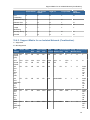
10.4. Network Service Providers Support Matrix .................................................................
73
73
73
73
73
74
74
74
iv
10.4.1. Individual .......................................................................................................
10.4.2. Support Matrix for an Isolated Network (Combination) ......................................
10.4.3. Support Matrix for Shared Network (Combination) ............................................
10.4.4. Support Matrix for Basic Zone ........................................................................
10.5. Network Offerings .....................................................................................................
10.5.1. Creating a New Network Offering ...................................................................
10.5.2. Changing the Network Offering on a Guest Network ........................................
10.5.3. Creating and Changing a Virtual Router Network Offering .................................
74
75
76
77
77
78
81
82
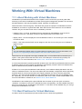
11. Working With Virtual Machines
85
11.1. About Working with Virtual Machines ......................................................................... 85
11.2. Best Practices for Virtual Machines ........................................................................... 85
11.2.1. Monitor VMs for Max Capacity ........................................................................ 86
11.2.2. Install Required Tools and Drivers .................................................................. 86
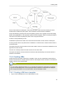
11.3. VM Lifecycle ............................................................................................................ 86
11.4. Creating VMs ........................................................................................................... 87
11.4.1. Creating a VM from a template ....................................................................... 87
11.4.2. Creating a VM from an ISO ............................................................................ 88
11.4.3. Configuring Usage of Linked Clones on VMware ............................................. 88
11.5. Accessing VMs ......................................................................................................... 89
11.6. Appending a Display Name to the Guest VM’s Internal Name ...................................... 89
11.7. Stopping and Starting VMs ....................................................................................... 90
11.8. Assigning VMs to Hosts ............................................................................................ 90
11.8.1. Affinity Groups ............................................................................................... 91
11.9. Virtual Machine Snapshots for VMware ...................................................................... 92
11.9.1. Limitations on VM Snapshots ......................................................................... 93
11.9.2. Configuring VM Snapshots ............................................................................. 93
11.9.3. Using VM Snapshots ..................................................................................... 93
11.10. Changing the VM Name, OS, or Group .................................................................... 94
11.11. Changing the Service Offering for a VM ................................................................... 95
11.11.1. CPU and Memory Scaling for Running VMs .................................................. 95
11.11.2. Updating Existing VMs ................................................................................. 96
11.11.3. Configuring Dynamic CPU and RAM Scaling ................................................. 96
11.11.4. How to Dynamically Scale CPU and RAM ..................................................... 96
11.11.5. Limitations ................................................................................................... 96
11.12. Resetting the Virtual Machine Root Volume on Reboot ............................................. 97
11.13. Moving VMs Between Hosts (Manual Live Migration) ................................................ 97
11.14. Deleting VMs .......................................................................................................... 98
11.15. Recovering a Destroyed VM .................................................................................... 98
11.16. Working with ISOs .................................................................................................. 98
11.16.1. Adding an ISO ............................................................................................. 99
11.16.2. Attaching an ISO to a VM ........................................................................... 100
11.16.3. Changing a VM's Base Image ..................................................................... 100
12. Working With Hosts
12.1. Adding Hosts ..........................................................................................................
12.2. Scheduled Maintenance and Maintenance Mode for Hosts ........................................
12.2.1. vCenter and Maintenance Mode ...................................................................
12.2.2. XenServer and Maintenance Mode ...............................................................
12.3. Disabling and Enabling Zones, Pods, and Clusters ...................................................
12.4. Removing Hosts .....................................................................................................
12.4.1. Removing XenServer and KVM Hosts ...........................................................
12.4.2. Removing vSphere Hosts .............................................................................
12.5. Re-Installing Hosts ..................................................................................................
12.6. Maintaining Hypervisors on Hosts ............................................................................
103
103
103
103
103
104
104
105
105
105
105
v
CloudPlatform (powered by Apache CloudStack) Version 4.2 Administrator's Guide
12.7. Using Cisco UCS as Bare Metal Host CloudPlatform ................................................
12.7.1. Registering a UCS Manager .........................................................................
12.7.2. Associating a Profile with a UCS Blade .........................................................
12.7.3. Disassociating a Profile from a UCS Blade ....................................................
12.8. Changing Host Password ........................................................................................
12.9. Over-Provisioning and Service Offering Limits ..........................................................
12.9.1. Limitations on Over-Provisioning in XenServer and KVM ................................
12.9.2. Requirements for Over-Provisioning ..............................................................
12.9.3. Setting Over-Provisioning Ratios ...................................................................
12.9.4. Service Offering Limits and Over-Provisioning ................................................
12.10. VLAN Provisioning ................................................................................................
12.10.1. VLAN Allocation Example ...........................................................................
12.10.2. Adding Non Contiguous VLAN Ranges ........................................................
12.10.3. Assigning VLANs to Isolated Networks ........................................................
105
106
106
107
107
108
109
109
109
110
110
111
111
112
13. Working with Templates
13.1. Creating Templates: Overview .................................................................................
13.2. Requirements for Templates ...................................................................................
13.3. Best Practices for Templates ...................................................................................
13.4. The Default Template .............................................................................................
13.5. Private and Public Templates ..................................................................................
13.6. Creating a Template from an Existing Virtual Machine ..............................................
13.7. Creating a Template from a Snapshot .....................................................................
13.8. Uploading Templates ..............................................................................................
13.9. Exporting Templates ...............................................................................................
13.10. Creating a Windows Template ...............................................................................
13.10.1. System Preparation for Windows Server 2008 R2 ........................................
13.10.2. System Preparation for Windows Server 2003 R2 ........................................
13.11. Importing Amazon Machine Images .......................................................................
13.12. Converting a Hyper-V VM to a Template ................................................................
13.13. Adding Password Management to Your Templates .................................................
13.13.1. Linux OS Installation ..................................................................................
13.13.2. Windows OS Installation .............................................................................
13.14. Deleting Templates ...............................................................................................
113
113
113
113
113
114
114
115
115
117
117
117
121
122
125
126
127
127
127
14. Working With Storage
14.1. Storage Overview ...................................................................................................
14.2. Primary Storage .....................................................................................................
14.2.1. Best Practices for Primary Storage ...............................................................
14.2.2. Runtime Behavior of Primary Storage ...........................................................
14.2.3. Hypervisor Support for Primary Storage ........................................................
14.2.4. Storage Tags ...............................................................................................
14.2.5. Maintenance Mode for Primary Storage .........................................................
14.3. Secondary Storage .................................................................................................
14.3.1. Best Practices for Secondary Storage ...........................................................
14.3.2. Changing the Secondary Storage IP Address ................................................
14.3.3. Changing Secondary Storage Servers ...........................................................
14.4. Working With Volumes ............................................................................................
14.4.1. Creating a New Volume ...............................................................................
14.4.2. Uploading an Existing Volume to a Virtual Machine ........................................
14.4.3. Attaching a Volume ......................................................................................
14.4.4. Detaching and Moving Volumes ....................................................................
14.4.5. VM Storage Migration ..................................................................................
14.4.6. Resizing Volumes ........................................................................................
14.4.7. Reset VM to New Root Disk on Reboot .........................................................
129
129
129
129
129
129
130
131
131
131
131
132
132
132
133
134
135
135
137
138
vi
14.4.8. Volume Deletion and Garbage Collection ......................................................
14.5. Working with Snapshots ..........................................................................................
14.5.1. Automatic Snapshot Creation and Retention ..................................................
14.5.2. Incremental Snapshots and Backup ..............................................................
14.5.3. Volume Status .............................................................................................
14.5.4. Snapshot Restore ........................................................................................
14.5.5. Snapshot Job Throttling ................................................................................
14.5.6. VMware Volume Snapshot Performance ........................................................
138
138
139
139
139
140
140
140
15. Working with Usage
15.1. Configuring the Usage Server .................................................................................
15.2. Setting Usage Limits ...............................................................................................
15.2.1. Globally Configured Limits ............................................................................
15.2.2. Default Account Resource Limits ..................................................................
15.2.3. Per-Domain Limits .......................................................................................
141
141
143
144
145
146
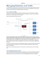
16. Managing Networks and Traffic
16.1. Guest Traffic ..........................................................................................................
16.2. Networking in a Pod ...............................................................................................
16.3. Networking in a Zone ..............................................................................................
16.4. Basic Zone Physical Network Configuration ..............................................................
16.5. Advanced Zone Physical Network Configuration .......................................................
16.5.1. Configuring Isolated Guest Network ..............................................................
16.5.2. Configure Public Traffic in an Advanced Zone ................................................
16.5.3. Configuring a Shared Guest Network ............................................................
16.6. Using Security Groups to Control Traffic to VMs .......................................................
16.6.1. About Security Groups .................................................................................
16.6.2. Security Groups in Advanced Zones (KVM Only) ...........................................
16.6.3. Enabling Security Groups .............................................................................
16.6.4. Adding a Security Group ..............................................................................
16.6.5. Adding Ingress and Egress Rules to a Security Group ....................................
16.7. External Firewalls and Load Balancers ....................................................................
16.7.1. About Using a NetScaler Load Balancer ........................................................
16.7.2. Configuring SNMPCommunity String on a RHEL Server .................................
16.7.3. Initial Setup of External Firewalls and Load Balancers ....................................
16.7.4. Ongoing Configuration of External Firewalls and Load Balancers .....................
16.8. Load Balancer Rules ..............................................................................................
16.8.1. Adding a Load Balancer Rule .......................................................................
16.8.2. Configuring AutoScale ..................................................................................
16.8.3. Sticky Session Policies for Load Balancer Rules ............................................
16.8.4. Health Checks for Load Balancer Rules ........................................................
16.9. Global Server Load Balancing .................................................................................
16.9.1. About Global Server Load Balancing .............................................................
16.9.2. Configuring GSLB ........................................................................................
16.10. Using Multiple Guest Networks ..............................................................................
16.10.1. Adding an Additional Guest Network ...........................................................
16.10.2. Reconfiguring Networks in VMs ..................................................................
16.11. Guest IP Ranges ..................................................................................................
16.12. Acquiring a New IP Address ..................................................................................
16.13. Releasing an IP Address .......................................................................................
16.14. Reserving Public IP Addresses and VLANs for Accounts .........................................
16.14.1. Dedicating IP Address Ranges to an Account ..............................................
16.14.2. Dedicating VLAN Ranges to an Account ......................................................
16.15. IP Reservation in Isolated Guest Networks .............................................................
16.15.1. IP Reservation Considerations ....................................................................
147
147
147
148
149
149
149
150
151
152
152
152
153
153
153
154
155
156
157
158
158
158
159
164
164
165
165
167
172
172
172
174
174
174
175
175
176
177
177
vii
CloudPlatform (powered by Apache CloudStack) Version 4.2 Administrator's Guide
16.15.2. Limitations .................................................................................................
16.15.3. Best Practices ............................................................................................
16.15.4. Reserving an IP Range ..............................................................................
16.16. Configuring Multiple IP Addresses on a Single NIC .................................................
16.16.1. Use Cases .................................................................................................
16.16.2. Guidelines .................................................................................................
16.16.3. Assigning Additional IPs to a VM ................................................................
16.16.4. Port Forwarding and StaticNAT Services Changes .......................................
16.17. Multiple Subnets in Shared Network ......................................................................
16.17.1. Prerequisites and Guidelines ......................................................................
16.17.2. Adding Multiple Subnets to a Shared Network ..............................................
16.18. About Elastic IP ....................................................................................................
16.19. Portable IPs .........................................................................................................
16.19.1. About Portable IP .......................................................................................
16.19.2. Configuring Portable IPs .............................................................................
16.19.3. Acquiring a Portable IP ...............................................................................
16.19.4. Transferring Portable IP ..............................................................................
16.20. Static NAT ............................................................................................................
16.20.1. Enabling or Disabling Static NAT ................................................................
16.21. IP Forwarding and Firewalling ...............................................................................
16.21.1. Egress Firewall Rules in an Advanced Zone ................................................
16.21.2. Firewall Rules ............................................................................................
16.21.3. Port Forwarding .........................................................................................
16.22. IP Load Balancing ................................................................................................
16.23. DNS and DHCP ...................................................................................................
16.24. Remote Access VPN ............................................................................................
16.24.1. Configuring Remote Access VPN ................................................................
16.24.2. Using Remote Access VPN with Windows ...................................................
16.24.3. Using Remote Access VPN with Mac OS X .................................................
16.24.4. Setting Up a Site-to-Site VPN Connection ....................................................
16.25. Isolation in Advanced Zone Using Private VLAN .....................................................
16.25.1. About Private VLAN ...................................................................................
16.25.2. Prerequisites ..............................................................................................
16.25.3. Creating a PVLAN-Enabled Guest Network ..................................................
16.26. About Inter-VLAN Routing .....................................................................................
16.27. Configuring a Virtual Private Cloud ........................................................................
16.27.1. About Virtual Private Clouds .......................................................................
16.27.2. Adding a Virtual Private Cloud ....................................................................
16.27.3. Adding Tiers ..............................................................................................
16.27.4. Configuring Network Access Control List .....................................................
16.27.5. Adding a Private Gateway to a VPC ............................................................
16.27.6. Deploying VMs to the Tier ..........................................................................
16.27.7. Deploying VMs to VPC Tier and Shared Networks .......................................
16.27.8. Acquiring a New IP Address for a VPC .......................................................
16.27.9. Releasing an IP Address Alloted to a VPC ..................................................
16.27.10. Enabling or Disabling Static NAT on a VPC ...............................................
16.27.11. Adding Load Balancing Rules on a VPC ....................................................
16.27.12. Adding a Port Forwarding Rule on a VPC ..................................................
16.27.13. Removing Tiers ........................................................................................
16.27.14. Editing, Restarting, and Removing a Virtual Private Cloud ...........................
16.28. Persistent Networks ..............................................................................................
16.28.1. Persistent Network Considerations ..............................................................
16.28.2. Creating a Persistent Guest Network ...........................................................
viii
178
178
178
178
179
179
179
179
180
180
180
181
183
183
184
184
185
185
185
186
186
188
189
189
190
190
190
191
192
192
200
200
201
201
202
204
204
206
207
209
212
215
215
216
217
218
219
225
226
227
227
227
228
17. Working with System Virtual Machines
17.1. The System VM Template .......................................................................................
17.2. Multiple System VM Support for VMware .................................................................
17.3. Console Proxy ........................................................................................................
17.3.1. Changing the Console Proxy SSL Certificate and Domain ...............................
17.4. Virtual Router .........................................................................................................
17.4.1. Configuring the Virtual Router .......................................................................
17.4.2. Upgrading a Virtual Router with System Service Offerings ..............................
17.4.3. Best Practices for Virtual Routers .................................................................
17.5. Secondary Storage VM ...........................................................................................
229
229
229
229
230
231
231
232
232
232
18. System Reliability and High Availability
18.1. HA for Management Server .....................................................................................
18.2. HA-Enabled Virtual Machines ..................................................................................
18.3. Dedicated HA Hosts ...............................................................................................
18.4. Primary Storage Outage and Data Loss ...................................................................
18.5. Secondary Storage Outage and Data Loss ..............................................................
18.6. Limiting the Rate of API Requests ...........................................................................
18.6.1. Configuring the API Request Rate ................................................................
18.6.2. Limitations on API Throttling .........................................................................
233
233
233
233
234
234
234
234
235
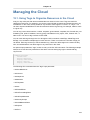
19. Managing the Cloud
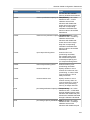
19.1. Using Tags to Organize Resources in the Cloud .......................................................
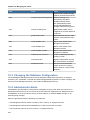
19.2. Setting Configuration Parameters ............................................................................
19.2.1. About Configuration Parameters ...................................................................
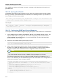
19.2.2. Setting Global Configuration Parameters .......................................................
19.2.3. Setting Local Configuration Parameters .........................................................
19.2.4. Granular Global Configuration Parameters .....................................................
19.3. Changing the Database Configuration ......................................................................
19.4. Administrator Alerts .................................................................................................
19.4.1. Customizing Alerts with Global Configuration Settings ....................................
19.4.2. Sending Alerts to External SNMP and Syslog Managers .................................
19.5. Customizing the Network Domain Name ..................................................................
19.6. Stopping and Restarting the Management Server .....................................................
237
237
238
238
239
239
240
242
242
243
243
245
246
20. CloudPlatform API
20.1. Provisioning and Authentication API ........................................................................
20.2. Allocators ...............................................................................................................
20.3. User Data and Meta Data .......................................................................................
247
247
247
247
21. Tuning
21.1. Performance Monitoring ..........................................................................................
21.2. Increase Management Server Maximum Memory .....................................................
21.3. Set Database Buffer Pool Size ................................................................................
21.4. Set and Monitor Total VM Limits per Host ................................................................
21.5. Configure XenServer dom0 Memory ........................................................................
249
249
249
249
250
250
22. Troubleshooting
22.1. Events ....................................................................................................................
22.1.1. Event Logs ..................................................................................................
22.1.2. Event Notification .........................................................................................
22.1.3. Standard Events ..........................................................................................
22.1.4. Long Running Job Events ............................................................................
22.1.5. Event Log Queries .......................................................................................
22.1.6. Deleting and Archiving Events and Alerts ......................................................
22.2. Working with Server Logs .......................................................................................
251
251
251
251
252
252
253
253
254
ix
CloudPlatform (powered by Apache CloudStack) Version 4.2 Administrator's Guide
22.3. Log Collection Utility cloud-bugtool ..........................................................................
22.3.1. Using cloud-bugtool .....................................................................................
22.4. Data Loss on Exported Primary Storage ..................................................................
22.5. Recovering a Lost Virtual Router .............................................................................
22.6. Maintenance mode not working on vCenter ..............................................................
22.7. Unable to deploy VMs from uploaded vSphere template ............................................
22.8. Unable to power on virtual machine on VMware .......................................................
22.9. Load balancer rules fail after changing network offering ............................................
255
255
255
256
256
257
257
258
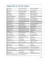
A. Event Types
259
B. Alerts
261
x
Chapter 1.
Getting More Information and Help
1.1. Additional Documentation Available
The following guides are available:
• Installation Guide — Covers initial installation of CloudPlatform. It aims to cover in full detail all the
steps and requirements to obtain a functioning cloud deployment.
At times, this guide mentions additional topics in the context of installation tasks, but does not
give full details on every topic. Additional details on many of these topics can be found in the
CloudPlatform Administration Guide. For example, security groups, firewall and load balancing
rules, IP address allocation, and virtual routers are covered in more detail in the Administration
Guide.
• Administration Guide — Discusses how to set up services for the end users of your cloud. Also
covers ongoing runtime management and maintenance. This guide discusses topics like domains,
accounts, service offerings, projects, guest networks, administrator alerts, virtual machines, storage,
and measuring resource usage.
• Developer's Guide — How to use the API to interact with CloudPlatform programmatically.
1.2. Citrix Knowledge Center
Troubleshooting articles by the Citrix support team are available in the Citrix Knowledge Center, at
1
support.citrix.com/product/cs/ .
1.3. Contacting Support
The support team is available to help customers plan and execute their installations. To contact the
2
support team, log in to the support portal at support.citrix.com/cloudsupport by using the account
credentials you received when you purchased your support contract.
1
2
http://support.citrix.com/product/cs/
http://support.citrix.com/cloudsupport
1
2
Chapter 2.
Concepts
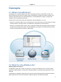
2.1. What Is CloudPlatform?
CloudPlatform is a software platform that pools computing resources to build public, private, and
hybrid Infrastructure as a Service (IaaS) clouds. CloudPlatform manages the network, storage, and
compute nodes that make up a cloud infrastructure. Use CloudPlatform to deploy, manage, and
configure cloud computing environments.
Typical users are service providers and enterprises. With CloudPlatform, you can:
• Set up an on-demand, elastic cloud computing service. Service providers can sell self service virtual
machine instances, storage volumes, and networking configurations over the Internet.
• Set up an on-premise private cloud for use by employees. Rather than managing virtual machines in
the same way as physical machines, with CloudPlatform an enterprise can offer self-service virtual
machines to users without involving IT departments.
2.2. What Can CloudPlatform Do?
Multiple Hypervisor Support
CloudPlatform works with a variety of hypervisors. A single cloud deployment can contain multiple
hypervisor implementations. You have the complete freedom to choose the right hypervisor for your
workload.
CloudPlatform is designed to work with open source Xen and KVM hypervisors as well as enterprisegrade hypervisors such as Citrix XenServer, VMware vSphere, and Oracle VM (OVM).
3
Chapter 2. Concepts
Massively Scalable Infrastructure Management
CloudPlatform can manage tens of thousands of servers installed in multiple geographically distributed
datacenters. The centralized management server scales linearly, eliminating the need for intermediate
cluster-level management servers. No single component failure can cause cloud-wide outage. Periodic
maintenance of the management server can be performed without affecting the functioning of virtual
machines running in the cloud.
Automatic Configuration Management
CloudPlatform automatically configures each guest virtual machine’s networking and storage settings.
CloudPlatform internally manages a pool of virtual appliances to support the cloud itself. These
appliances offer services such as firewalling, routing, DHCP, VPN access, console proxy, storage
access, and storage replication. The extensive use of virtual appliances simplifies the installation,
configuration, and ongoing management of a cloud deployment.
Graphical User Interface
CloudPlatform offers an administrator's Web interface, used for provisioning and managing the cloud,
as well as an end-user's Web interface, used for running VMs and managing VM templates. The UI
can be customized to reflect the desired service provider or enterprise look and feel.
API and Extensibility
CloudPlatform provides an API that gives programmatic access to all the management features
available in the UI. This API enables the creation of command line tools and new user interfaces to
suit particular needs.
The CloudPlatform pluggable allocation architecture allows the creation of new types of allocators for
the selection of storage and hosts.
High Availability
CloudPlatform has a number of features to increase the availability of the system. The Management
Server itself, which is the main controlling software at the heart of CloudPlatform, may be deployed
in a multi-node installation where the servers are load balanced. MySQL may be configured to use
replication to provide for a manual failover in the event of database loss. For the hosts, CloudPlatform
supports NIC bonding and the use of separate networks for storage as well as iSCSI Multipath.
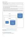
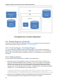
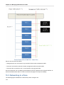
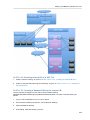
2.3. Deployment Architecture Overview
A CloudPlatform installation consists of two parts: the Management Server and the cloud infrastructure
that it manages. When you set up and manage a CloudPlatform cloud, you provision resources such
as hosts, storage devices, and IP addresses into the Management Server, and the Management
Server manages those resources.
The minimum production installation consists of one machine running the CloudPlatform Management
Server and another machine to act as the cloud infrastructure (in this case, a very simple infrastructure
consisting of one host running hypervisor software). In a trial installation, a single machine can act as
both the Management Server and the hypervisor host (using the KVM hypervisor).
4
Management Server Overview
A more full-featured installation consists of a highly-available multi-node Management Server
installation and up to thousands of hosts using any of several advanced networking setups. For
information about deployment options, see Choosing a Deployment Architecture in the Installation
Guide.
2.3.1. Management Server Overview
The Management Server is the CloudPlatform software that manages cloud resources. By interacting
with the Management Server through its UI or API, you can configure and manage your cloud
infrastructure.
The Management Server runs on a dedicated server or VM. It controls allocation of virtual machines
to hosts and assigns storage and IP addresses to the virtual machine instances. The Management
Server runs in a Tomcat container and uses a MySQL database for persistence.
The machine where the Management Server runs must meet the system requirements described in
Minimum System Requirements in the Installation Guide.
The Management Server:
• Provides the web user interface for the administrator and a reference user interface for end users.
• Provides the APIs for CloudPlatform.
• Manages the assignment of guest VMs to particular hosts.
• Manages the assignment of public and private IP addresses to particular accounts.
• Manages the allocation of storage to guests as virtual disks.
• Manages snapshots, templates, and ISO images, possibly replicating them across data centers.
• Provides a single point of configuration for the cloud.
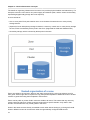
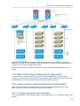
2.3.2. Cloud Infrastructure Overview
The Management Server manages one or more zones (typically, datacenters) containing host
computers where guest virtual machines will run. The cloud infrastructure is organized as follows:
• Region: To increase reliability of the cloud, you can optionally group resources into multiple
geographic regions. A region consists of one or more zones.
5
Chapter 2. Concepts
• Zone: Typically, a zone is equivalent to a single datacenter. A zone consists of one or more pods
and secondary storage.
• Pod: A pod is usually one rack of hardware that includes a layer-2 switch and one or more clusters.
• Cluster: A cluster consists of one or more hosts and primary storage.
• Host: A single compute node within a cluster. The hosts are where the actual cloud services run in
the form of guest virtual machines.
• Primary storage is associated with a cluster, and it can also be provisioned on a zone-wide basis. It
stores the disk volumes for all the VMs running on hosts in that cluster.
• Secondary storage is associated with a zone, and it can also be provisioned as object storage that
is available throughout the cloud. It stores templates, ISO images, and disk volume snapshots.
More Information
For more information, see Chapter 3, Cloud Infrastructure Concepts.
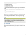
2.3.3. Networking Overview
CloudPlatform offers two types of networking scenario:
6
Networking Overview
• Basic. Provides a single network where guest isolation can be provided through layer-3 means such
as security groups (IP address source filtering).
• Advanced. For more sophisticated network topologies. This network model provides the most
flexibility in defining guest networks and providing guest isolation.
For more details, see Network Setup in the Installation Guide.
7
8
Chapter 3.
Cloud Infrastructure Concepts
3.1. About Regions
To increase reliability of the cloud, you can optionally group resources into multiple geographic
regions. A region is the largest available organizational unit within a CloudPlatform deployment. A
region is made up of several availability zones, where each zone is equivalent to a datacenter. Each
region is controlled by its own cluster of Management Servers, running in one of the zones. The zones
in a region are typically located in close geographical proximity. Regions are a useful technique for
providing fault tolerance and disaster recovery.
By grouping zones into regions, the cloud can achieve higher availability and scalability. User
accounts can span regions, so that users can deploy VMs in multiple, widely-dispersed regions.
Even if one of the regions becomes unavailable, the services are still available to the end-user
through VMs deployed in another region. And by grouping communities of zones under their own
nearby Management Servers, the latency of communications within the cloud is reduced compared to
managing widely-dispersed zones from a single central Management Server.
Usage records can also be consolidated and tracked at the region level, creating reports or invoices
for each geographic region.
Regions are visible to the end user. When a user starts a guest VM on a particular CloudPlatform
Management Server, the user is implicitly selecting that region for their guest. Users might also be
required to copy their private templates to additional regions to enable creation of guest VMs using
their templates in those regions.
3.2. About Zones
A zone is the second largest organizational unit within a CloudPlatform deployment. A zone typically
corresponds to a single datacenter, although it is permissible to have multiple zones in a datacenter.
9
Chapter 3. Cloud Infrastructure Concepts
The benefit of organizing infrastructure into zones is to provide physical isolation and redundancy. For
example, each zone can have its own power supply and network uplink, and the zones can be widely
separated geographically (though this is not required).
A zone consists of:
• One or more pods. Each pod contains one or more clusters of hosts and one or more primary
storage servers.
• (Optional) If zone-wide primary storage is desired, a zone may contain one or more primary storage
servers, which are shared by all the pods in the zone. (Supported for KVM and VMware hosts)
• Secondary storage, which is shared by all the pods in the zone.
Zones are visible to the end user. When a user starts a guest VM, the user must select a zone for
their guest. Users might also be required to copy their private templates to additional zones to enable
creation of guest VMs using their templates in those zones.
Zones can be public or private. Public zones are visible to all users. This means that any user may
create a guest in that zone. Private zones are reserved for a specific domain. Only users in that
domain or its subdomains may create guests in that zone.
Hosts in the same zone are directly accessible to each other without having to go through a firewall.
Hosts in different zones can access each other through statically configured VPN tunnels.
10
About Pods
For each zone, the administrator must decide the following.
• How many pods to place in a zone.
• How many clusters to place in each pod.
• How many hosts to place in each cluster.
• (Optional) If zone-wide primary storage is being used, decide how many primary storage servers to
place in each zone and total capacity for these storage servers. (Supported for KVM and VMware
hosts)
• How many primary storage servers to place in each cluster and total capacity for these storage
servers.
• How much secondary storage to deploy in a zone.
When you add a new zone, you will be prompted to configure the zone’s physical network and add the
first pod, cluster, host, primary storage, and secondary storage.
(VMware) In order to support zone-wide functions for VMware, CloudPlatform is aware of VMware
Datacenters and can map each Datacenter to a CloudPlatform zone. To enable features like storage
live migration and zone-wide primary storage for VMware hosts, CloudPlatform has to make sure
that a zone contains only a single VMware Datacenter. Therefore, when you are creating a new
CloudPlatform zone, you can select a VMware Datacenter for the zone. If you are provisioning multiple
VMware Datacenters, each one will be set up as a single zone in CloudPlatform.
Note
If you are upgrading from a previous CloudPlatform version, and your existing deployment
contains a zone with clusters from multiple VMware Datacenters, that zone will not be forcibly
migrated to the new model. It will continue to function as before. However, any new zone-wide
operations introduced in CloudPlatform 4.2, such as zone-wide primary storage and live storage
migration, will not be available in that zone.
3.3. About Pods
A pod often represents a single rack. Hosts in the same pod are in the same subnet. A pod is the
third-largest organizational unit within a CloudPlatform deployment. Pods are contained within zones,
and zones can be contained within regions. Each zone can contain one or more pods. A pod consists
of one or more clusters of hosts and one or more primary storage servers. Pods are not visible to the
end user.
11
Chapter 3. Cloud Infrastructure Concepts
3.4. About Clusters
A cluster provides a way to group hosts. To be precise, a cluster is a XenServer server pool, a set
of KVM servers, a set of OVM hosts, or a VMware cluster preconfigured in vCenter. The hosts in a
cluster all have identical hardware, run the same hypervisor, are on the same subnet, and access the
same shared primary storage. Virtual machine instances (VMs) can be live-migrated from one host to
another within the same cluster without interrupting service to the user.
A cluster is the fourth-largest organizational unit within a CloudPlatform deployment. Clusters
are contained within pods, pods are contained within zones, and zones can be contained within
regions. Size of the cluster is only limited by the underlying hypervisor, although the CloudPlatform
recommends you stay below the theoretically allowed maximum cluster size in most cases.
A cluster consists of one or more hosts and one or more primary storage servers.
Even when local storage is used, clusters are still required. In this case, there is just one host per
cluster.
(VMware) If you use VMware hypervisor hosts in your CloudPlatform deployment, each VMware
cluster is managed by a vCenter server. The CloudPlatform administrator must register the vCenter
12
About Hosts
server with CloudPlatform. There may be multiple vCenter servers per zone. Each vCenter server may
manage multiple VMware clusters.
3.5. About Hosts
A host is a single computer. Hosts provide the computing resources that run guest virtual machines.
Each host has hypervisor software installed on it to manage the guest VMs. For example, a host can
be a Citrix XenServer server, a Linux KVM-enabled server, or an ESXi server.
The host is the smallest organizational unit within a CloudPlatform deployment. Hosts are contained
within clusters, clusters are contained within pods, pods are contained within zones, and zones can be
contained within regions.
Hosts in a CloudPlatform deployment:
• Provide the CPU, memory, storage, and networking resources needed to host the virtual machines
• Interconnect using a high bandwidth TCP/IP network and connect to the Internet
• May reside in multiple data centers across different geographic locations
• May have different capacities (different CPU speeds, different amounts of RAM, etc.), although the
hosts within a cluster must all be homogeneous
Additional hosts can be added at any time to provide more capacity for guest VMs.
CloudPlatform automatically detects the amount of CPU and memory resources provided by the hosts.
Hosts are not visible to the end user. An end user cannot determine which host their guest has been
assigned to.
For a host to function in CloudPlatform, you must do the following:
• Install hypervisor software on the host
• Assign an IP address to the host
• Ensure the host is connected to the CloudPlatform Management Server.
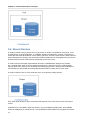
3.6. About Primary Storage
Primary storage is associated with a cluster or (in KVM and VMware) a zone, and it stores the disk
volumes for all the VMs running on hosts.
You can add multiple primary storage servers to a cluster or zone. At least one is required. It is
typically located close to the hosts for increased performance. CloudPlatform manages the allocation
of guest virtual disks to particular primary storage devices.
It is useful to set up zone-wide primary storage when you want to avoid extra data copy operations.
With cluster-based primary storage, data in the primary storage is directly available only to VMs
within that cluster. If a VM in a different cluster needs some of the data, it must be copied from one
cluster to another, using the zone's secondary storage as an intermediate step. This operation can be
unnecessarily time-consuming.
CloudPlatform is designed to work with all standards-compliant iSCSI and NFS servers that are
supported by the underlying hypervisor, including, for example:
13
Chapter 3. Cloud Infrastructure Concepts
• Dell EqualLogic™ for iSCSI
• Network Appliances filers for NFS and iSCSI
• Scale Computing for NFS
If you intend to use only local disk for your installation, you can skip adding separate primary storage.
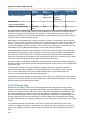
3.7. About Secondary Storage
Secondary storage stores the following:
• Templates — OS images that can be used to boot VMs and can include additional configuration
information, such as installed applications
• ISO images — disc images containing data or bootable media for operating systems
• Disk volume snapshots — saved copies of VM data which can be used for data recovery or to
create new templates
The items in secondary storage are available to all hosts in the scope of the secondary storage, which
may be defined as per zone or per region.
CloudPlatform manages the allocation of guest virtual disks to particular primary storage devices.
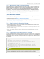
To make items in secondary storage available to all hosts throughout the cloud, you can add object
storage in addition to the zone-based NFS Secondary Staging Store. It is not necessary to copy
templates and snapshots from one zone to another, as would be required when using zone NFS
alone. Everything is available everywhere.
Object storage is provided through third-party software such as Amazon Simple Storage Service (S3)
or any other object storage that supports the S3 interface. Additional third party object storages can be
integrated with CloudPlatform by writing plugin software that uses the object storage plugin capability.
CloudPlatform provides some plugins which we have already written for you using this storage plugin
1
capability. The provided plugins are for OpenStack Object Storage (Swift, swift.openstack.org )
and Amazon Simple Storage Service (S3) object storage. The S3 plugin can be used for any object
storage that supports the Amazon S3 interface. When using one of these storage plugins, you
configure Swift or S3 storage for the entire CloudPlatform, then set up the NFS Secondary Staging
Store for each zone. The NFS storage in each zone acts as a staging area through which all templates
and other secondary storage data pass before being forwarded to Swift or S3. The backing object
storage acts as a cloud-wide resource, making templates and other data available to any zone in the
cloud.
There is no hierarchy in the Swift storage, just one Swift container per storage object. Any secondary
storage in the whole cloud can pull a container from Swift at need.
3.8. About Physical Networks
Part of adding a zone is setting up the physical network. One or (in an advanced zone) more physical
networks can be associated with each zone. The network corresponds to a NIC on the hypervisor
host. Each physical network can carry one or more types of network traffic. The choices of traffic
1
http://swift.openstack.org
14
Basic Zone Network Traffic Types
type for each network vary depending on whether you are creating a zone with basic networking or
advanced networking.
A physical network is the actual network hardware and wiring in a zone. A zone can have multiple
physical networks. An administrator can:
• Add/Remove/Update physical networks in a zone
• Configure VLANs on the physical network
• Configure a name so the network can be recognized by hypervisors
• Configure the service providers (firewalls, load balancers, etc.) available on a physical network
• Configure the IP addresses trunked to a physical network
• Specify what type of traffic is carried on the physical network, as well as other properties like
network speed
3.8.1. Basic Zone Network Traffic Types
When basic networking is used, there can be only one physical network in the zone. That physical
network carries the following traffic types:
• Guest. When end users run VMs, they generate guest traffic. The guest VMs communicate with
each other over a network that can be referred to as the guest network. Each pod in a basic zone
is a broadcast domain, and therefore each pod has a different IP range for the guest network. The
administrator must configure the IP range for each pod.
• Management. When CloudPlatform’s internal resources communicate with each other, they
generate management traffic. This includes communication between hosts, system VMs (VMs
used by CloudPlatform to perform various tasks in the cloud), and any other component that
communicates directly with the CloudPlatform Management Server. You must configure the IP
range for the system VMs to use.
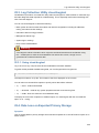
Note
We strongly recommend the use of separate NICs for management traffic and guest traffic.
• Public. Public traffic is generated when VMs in the cloud access the Internet. Publicly accessible IPs
must be allocated for this purpose. End users can use the CloudPlatform UI to acquire these IPs
to implement NAT between their guest network and the public network, as described in Acquiring
a New IP Address. Public traffic is generated only in EIP-enabled basic zones. For information on
Elastic IP, see Section 16.18, “About Elastic IP”.
• Storage. Traffic such as VM templates and snapshots, which is sent between the secondary storage
VM and secondary storage servers. CloudPlatform uses a separate Network Interface Controller
(NIC) named storage NIC for storage network traffic. Use of a storage NIC that always operates on
a high bandwidth network allows fast template and snapshot copying. You must configure the IP
range to use for the storage network.
In a basic network, configuring the physical network is fairly straightforward. In most cases, you only
need to configure one guest network to carry traffic that is generated by guest VMs. If you use a
NetScaler load balancer and enable its elastic IP and elastic load balancing (EIP and ELB) features,
15
Chapter 3. Cloud Infrastructure Concepts
you must also configure a network to carry public traffic. CloudPlatform takes care of presenting the
necessary network configuration steps to you in the UI when you add a new zone.
3.8.2. Basic Zone Guest IP Addresses
When basic networking is used, CloudPlatform will assign IP addresses in the CIDR of the pod to the
guests in that pod. The administrator must add a direct IP range on the pod for this purpose. These
IPs are in the same VLAN as the hosts.
3.8.3. Advanced Zone Network Traffic Types
When advanced networking is used, there can be multiple physical networks in the zone. Each
physical network can carry one or more traffic types, and you need to let CloudPlatform know which
type of network traffic you want each network to carry. The traffic types in an advanced zone are:
• Guest. When end users run VMs, they generate guest traffic. The guest VMs communicate with
each other over a network that can be referred to as the guest network. This network can be
isolated or shared. In an isolated guest network, the administrator needs to reserve VLAN ranges to
provide isolation for each CloudPlatform account’s network (potentially a large number of VLANs). In
a shared guest network, all guest VMs share a single network.
• Management. When CloudPlatform’s internal resources communicate with each other, they
generate management traffic. This includes communication between hosts, system VMs (VMs
used by CloudPlatform to perform various tasks in the cloud), and any other component that
communicates directly with the CloudPlatform Management Server. You must configure the IP
range for the system VMs to use.
• Public. Public traffic is generated when VMs in the cloud access the Internet. Publicly accessible IPs
must be allocated for this purpose. End users can use the CloudPlatform UI to acquire these IPs to
implement NAT between their guest network and the public network, as described in “Acquiring a
New IP Address” in the Administration Guide.
• Storage. Traffic such as VM templates and snapshots, which is sent between the secondary storage
VM and secondary storage servers. CloudPlatform uses a separate Network Interface Controller
(NIC) named storage NIC for storage network traffic. Use of a storage NIC that always operates on
a high bandwidth network allows fast template and snapshot copying. You must configure the IP
range to use for the storage network.
These traffic types can each be on a separate physical network, or they can be combined with certain
restrictions. When you use the Add Zone wizard in the UI to create a new zone, you are guided into
making only valid choices.
3.8.4. Advanced Zone Guest IP Addresses
When advanced networking is used, the administrator can create additional networks for use by the
guests. These networks can span the zone and be available to all accounts, or they can be scoped
to a single account, in which case only the named account may create guests that attach to these
networks. The networks are defined by a VLAN ID, IP range, and gateway. The administrator may
provision thousands of these networks if desired. Additionally, the administrator can reserve a part of
the IP address space for non-CloudPlatform VMs and servers (see Section 16.15, “IP Reservation in
Isolated Guest Networks”).
16
Advanced Zone Public IP Addresses
3.8.5. Advanced Zone Public IP Addresses
When advanced networking is used, the administrator can create additional networks for use by the
guests. These networks can span the zone and be available to all accounts, or they can be scoped
to a single account, in which case only the named account may create guests that attach to these
networks. The networks are defined by a VLAN ID, IP range, and gateway. The administrator may
provision thousands of these networks if desired.
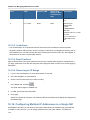
3.8.6. System Reserved IP Addresses
In each zone, you need to configure a range of reserved IP addresses for the management network.
This network carries communication between the CloudPlatform Management Server and various
system VMs, such as Secondary Storage VMs, Console Proxy VMs, and DHCP.
The reserved IP addresses must be unique across the cloud. You cannot, for example, have a host in
one zone which has the same private IP address as a host in another zone.
The hosts in a pod are assigned private IP addresses. These are typically RFC1918 addresses. The
Console Proxy and Secondary Storage system VMs are also allocated private IP addresses in the
CIDR of the pod that they are created in.
Make sure computing servers and Management Servers use IP addresses outside of the System
Reserved IP range. For example, suppose the System Reserved IP range starts at 192.168.154.2 and
ends at 192.168.154.7. CloudPlatform can use .2 to .7 for System VMs. This leaves the rest of the pod
CIDR, from .8 to .254, for the Management Server and hypervisor hosts.
In all zones:
Provide private IPs for the system in each pod and provision them in CloudPlatform.
For KVM and XenServer, the recommended number of private IPs per pod is one per host. If you
expect a pod to grow, add enough private IPs now to accommodate the growth.
In a zone that uses advanced networking:
When advanced networking is being used, the number of private IP addresses available in each pod
varies depending on which hypervisor is running on the nodes in that pod. Citrix XenServer and KVM
use link-local addresses, which in theory provide more than 65,000 private IP addresses within the
address block. As the pod grows over time, this should be more than enough for any reasonable
number of hosts as well as IP addresses for guest virtual routers. VMWare ESXi, by contrast uses
any administrator-specified subnetting scheme, and the typical administrator provides only 255 IPs
per pod. Since these are shared by physical machines, the guest virtual router, and other entities, it is
possible to run out of private IPs when scaling up a pod whose nodes are running ESXi.
To ensure adequate headroom to scale private IP space in an ESXi pod that uses advanced
networking, use one or more of the following techniques:
• Specify a larger CIDR block for the subnet. A subnet mask with a /20 suffix will provide more than
4,000 IP addresses.
• Create multiple pods, each with its own subnet. For example, if you create 10 pods and each pod
has 255 IPs, this will provide 2,550 IP addresses.
For vSphere with advanced networking, we recommend provisioning enough private IPs for your total
number of customers, plus enough for the required CloudPlatform System VMs. Typically, about 10
additional IPs are required for the System VMs. For more information about System VMs, see Working
with System Virtual Machines in the Administrator's Guide.
17
18
Chapter 4.
Accounts
4.1. Accounts, Users, and Domains
Accounts
An account typically represents a customer of the service provider or a department in a large
organization. Multiple users can exist in an account.
Domains
Accounts are grouped by domains. Domains usually contain multiple accounts that have some logical
relationship to each other and a set of delegated administrators with some authority over the domain
and its subdomains. For example, a service provider with several resellers could create a domain for
each reseller.
For each account created, the Cloud installation creates three different types of user accounts: root
administrator, domain administrator, and user.
Users
Users are like aliases in the account. Users in the same account are not isolated from each other, but
they are isolated from users in other accounts. Most installations need not surface the notion of users;
they just have one user per account. The same user cannot belong to multiple accounts.
Username is unique in a domain across accounts in that domain. The same username can exist in
other domains, including sub-domains. Domain name can repeat only if the full pathname from root is
unique. For example, you can create root/d1, as well as root/foo/d1, and root/sales/d1.
Administrators are accounts with special privileges in the system. There may be multiple
administrators in the system. Administrators can create or delete other administrators, and change the
password for any user in the system.
Domain Administrators
Domain administrators can perform administrative operations for users who belong to that domain.
Domain administrators do not have visibility into physical servers or other domains.
Root Administrator
Root administrators have complete access to the system, including managing templates, service
offerings, customer care administrators, and domains
Resource Ownership
Resources belong to the account, not individual users in that account. For example, billing, resource
limits, and so on are maintained by the account, not the users. A user can operate on any resource in
the account provided the user has privileges for that operation. The privileges are determined by the
role. A root administrator can change the ownership of any virtual machine from one account to any
other account by using the assignVirtualMachine API. A domain or sub-domain administrator can do
the same for VMs within the domain from one account to any other account in the domain or any of its
sub-domains.
19
Chapter 4. Accounts
4.1.1. Dedicating Resources to Accounts and Domains
The root administrator can dedicate resources to a specific domain or account that needs private
infrastructure for additional security or performance guarantees. A zone, pod, cluster, or host can be
reserved by the root administrator for a specific domain or account. Only users in that domain or its
subdomain may use the infrastructure. For example, only users in a given domain can create guests in
a zone dedicated to that domain.
There are several types of dedication available:
• Explicit dedication. A zone, pod, cluster, or host is dedicated to an account or domain by the root
administrator during initial deployment and configuration.
• Strict implicit dedication. A host will not be shared across multiple accounts. For example, strict
implicit dedication is useful for deployment of certain types of applications, such as desktops, where
no host can be shared between different accounts without violating the desktop software's terms of
license.
• Preferred implicit dedication. The VM will be deployed in dedicated infrastructure if possible.
Otherwise, the VM can be deployed in shared infrastructure.
4.1.1.1. How to Dedicate a Zone, Cluster, Pod, or Host to an Account or
Domain
For explicit dedication: When deploying a new zone, pod, cluster, or host, the root administrator can
click the Dedicated checkbox, then choose a domain or account to own the resource.
To explicitly dedicate an existing zone, pod, cluster, or host: log in as the root admin, find the resource
in the UI, and click the Dedicate button.
For implicit dedication: The administrator creates a compute service offering and in the Deployment
Planner field, chooses ImplicitDedicationPlanner. Then in Planner Mode, the administrator specifies
either Strict or Preferred, depending on whether it is permissible to allow some use of shared
resources when dedicated resources are not available. Whenever a user creates a VM based on this
service offering, it is allocated on one of the dedicated hosts.
4.1.1.2. How to Use Dedicated Hosts
To use an explicitly dedicated host, use the explicit-dedicated type of affinity group (see
Section 11.8.1, “Affinity Groups”). For example, when creating a new VM, an end user can choose to
place it on dedicated infrastructure. This operation will succeed only if some infrastructure has already
been assigned as dedicated to the user's account or domain.
4.1.1.3. Behavior of Dedicated Hosts, Clusters, Pods, and Zones
The administrator can live migrate VMs away from dedicated hosts if desired, whether the destination
is a host reserved for a different account/domain or a host that is shared (not dedicated to any
particular account or domain). CloudPlatform will generate an alert, but the operation is allowed.
Dedicated hosts can be used in conjunction with host tags. If both a host tag and dedication are
requested, the VM will be placed only on a host that meets both requirements. If there is no dedicated
resource available to that user that also has the host tag requested by the user, then the VM will not
deploy.
20
Using an LDAP Server for User Authentication
If you delete an account or domain, any hosts, clusters, pods, and zones that were dedicated to it are
freed up. They will now be available to be shared by any account or domain, or the administrator may
choose to re-dedicate them to a different account or domain.
System VMs and virtual routers affect the behavior of host dedication. System VMs and virtual routers
are owned by the CloudPlatform system account, and they can be deployed on any host. They do
not adhere to explicit dedication. The presence of system vms and virtual routers on a host makes it
unsuitable for strict implicit dedication. The host can not be used for strict implicit dedication, because
the host already has VMs of a specific account (the default system account). However, a host with
system VMs or virtual routers can be used for preferred implicit dedication.
4.2. Using an LDAP Server for User Authentication
You can use an external LDAP server, such as Microsoft Active Directory or ApacheDS, to
authenticate CloudPlatform end-users. Just map CloudPlatform accounts to the corresponding LDAP
accounts using a query filter. The query filter is written using the query syntax of the particular LDAP
server, and can include special wildcard characters provided by CloudPlatform for matching common
values such as the user’s email address and name. CloudPlatform will search the external LDAP
directory tree starting at a specified base directory and return the distinguished name (DN) and
password of the matching user. This information along with the given password is used to authenticate
the user.
4.2.1. Configuring an LDAP Server
You can add or remove an LDAP server to CloudPlatform for user authentication. To set up LDAP
authentication, you provide the following:
• Hostname or IP address and listening port of the LDAP server
• Base directory and query filter
• Search user DN credentials, which give CloudPlatform permission to search on the LDAP server
• SSL keystore and password, if SSL is used
4.2.1.1. Adding an LDAP Server
1. Log in to the CloudPlatform.
2. From the left navigational bar, click Global Settings.
3. From the Select view drop down, select LDAP Configuration.
4. Click Configure LDAP.
The Configure LDAP dialog is displayed.
21
Chapter 4. Accounts
5. Specify the following:
• Bind DN: The full distinguished name (DN), including common name (CN), of an LDAP user
account that has the necessary privileges to search users.
For example:
cn=admin,cn=users,dc=mycom,dc=com
This user account must have at least domain user privileges.
• Bind Password: The password used in association with the Bind DN user account.
• Hostname: Hostname or IP address.
• Query Filter: Searches external LDAP directory tree for corresponding CloudPlatform accounts.
The query filter is written by using the query syntax of the particular LDAP server, and can
include special wild card characters provided by CloudPlatform for matching common values,
such as the user’s email address and name.
• Port: The Listening port of the LDAP server. The default is 389.
• SSL: Specify SSL Trust Store and password, if SSL is used.
• Trust Store:
• Trust Store Password:
22
Example LDAP Configuration Commands
6. Click OK.
4.2.1.2. Removing an LDAP Configuration
1. Log in to the CloudPlatform.
2. From the left navigational bar, click Global Settings.
3. From the Select view drop down, select LDAP Configuration.
4. In the Quick View, click Remove LDAP.
Alternatively, you can click Remove LDAP in the LDAP Configuration Details page.
4.2.2. Example LDAP Configuration Commands
To understand the examples in this section, you need to know the basic concepts behind calling the
CloudPlatform API, which are explained in the Developer’s Guide.
The following shows an example invocation of ldapConfig with an ApacheDS LDAP server
http://127.0.0.1:8080/client/api?command=ldapConfig&hostname=127.0.0.1&searchbase=ou
%3Dtesting%2Co%3Dproject&queryfilter=%28%26%28uid%3D%25u%29%29&binddn=cn%3DJohn+Singh%2Cou
%3Dtesting%2Co%project&bindpass=secret&port=10389&ssl=true&truststore=C%3A%2Fcompany%2Finfo
%2Ftrusted.ks&truststorepass=secret&response=json&apiKey=YourAPIKey&signature=YourSignatureHash
The command must be URL-encoded. Here is the same example without the URL encoding:
http://127.0.0.1:8080/client/api?command=ldapConfig
&hostname=127.0.0.1
&searchbase=ou=testing,o=project
&queryfilter=(&(%uid=%u))
&binddn=cn=John+Singh,ou=testing,o=project
&bindpass=secret
&port=10389
&ssl=true
&truststore=C:/company/info/trusted.ks
&truststorepass=secret
&response=json
&apiKey=YourAPIKey&signature=YourSignatureHash
The following shows a similar command for Active Directory. Here, the search base is the testing
group within a company, and the users are matched up based on email address.
http://127.127.0.0:8080/client/api?command=ldapConfig&hostname=127.147.28.250&searchbase=OU
%3Dtesting%2CDC%3Dcompany&queryfilter=%28%26%28mail%3D
%25e%29%29 &binddn=CN%3DAdministrator%2COU%3Dtesting%2CDC
%3Dcompany&bindpass=1111_aaaa&port=389&response=json&apiKey=YourAPIKey&signature=YourSignatureHash
The next few sections explain some of the concepts you will need to know when filling out the
ldapConfig parameters.
4.2.3. Search Base
An LDAP query is relative to a given node of the LDAP directory tree, called the search base. The
search base is the distinguished name (DN) of a level of the directory tree below which all users can
be found. The users can be in the immediate base directory or in some subdirectory. The search base
may be equivalent to the organization, group, or domain name. The syntax for writing a DN varies
23
Chapter 4. Accounts
depending on which LDAP server you are using. A full discussion of distinguished names is outside
the scope of our documentation. The following table shows some examples of search bases to find
users in the testing department..
LDAP Server
Example Search Base DN
ApacheDS
ou=testing,o=project
Active Directory
OU=testing, DC=company
4.2.4. Query Filter
The query filter is used to find a mapped user in the external LDAP server. The query filter should
uniquely map the CloudPlatform user to LDAP user for a meaningful authentication. For more
information about query filter syntax, consult the documentation for your LDAP server.
The CloudPlatform query filter wild cards are:
Query Filter Wildcard
Description
%u
User name
%e
Email address
%n
First and last name
4.2.4.1. Active Directory
The following examples assume that you are using Active Directory. Refer to user attributes from the
Active Directory schema.
If the CloudPlatform user name is the same as the LDAP user ID:
(sAMAccountName=%u)
If the CloudPlatform user name is the LDAP display name:
(displayName=%u)
To find a user by email address:
(mail=%e)
4.2.4.2. ApacheDS
If your LDAP server is ApacheDS, consider the following examples:
If the CloudPlatform user name is the same as the LDAP user ID:
(uid=%u)
To find a user by email address:
(mail=%e)
Enter the query filers in CloudPlatform in the following format:
24
Search User Bind DN
(&(sAMAccountName=%u)
or (&(mail=%e))
4.2.5. Search User Bind DN
The bind DN is the user on the external LDAP server permitted to search the LDAP directory within the
defined search base. When the DN is returned, the DN and passed password are used to authenticate
the CloudPlatform user with an LDAP bind. A full discussion of bind DNs is outside the scope of our
documentation. The following table shows some examples of bind DNs.
LDAP Server
Example Bind DN
ApacheDS
cn=Administrator,dc=testing,ou=project,ou=org
Active Directory
CN=Administrator, OU=testing, DC=company,
DC=com
4.2.6. SSL Keystore Path and Password
If the LDAP server requires SSL, you need to enable it in the ldapConfig command by setting the
parameters ssl, truststore, and truststorepass. Before enabling SSL for ldapConfig, you need to get
the certificate which the LDAP server is using and add it to a trusted keystore. You will need to know
the path to the keystore and the password.
25
26
Chapter 5.
User Services Overview
In addition to the physical and logical infrastructure of your cloud, and the CloudPlatform software and
servers, you also need a layer of user services so that people can actually make use of the cloud.
This means not just a user UI, but a set of options and resources that users can choose from, such
as templates for creating virtual machines, disk storage, and more. If you are running a commercial
service, you will be keeping track of what services and resources users are consuming and charging
them for that usage. Even if you do not charge anything for people to use your cloud – say, if the users
are strictly internal to your organization, or just friends who are sharing your cloud – you can still keep
track of what services they use and how much of them.
5.1. Service Offerings, Disk Offerings, Network Offerings,
and Templates
A user creating a new instance can make a variety of choices about its characteristics and capabilities.
CloudPlatform provides several ways to present users with choices when creating a new instance:
• Service Offerings, defined by the CloudPlatform administrator, provide a choice of CPU speed,
number of CPUs, RAM size, tags on the root disk, and other choices. See Creating a New Compute
Offering.
• Disk Offerings, defined by the CloudPlatform administrator, provide a choice of disk size for primary
data storage. See Creating a New Disk Offering.
• Network Offerings, defined by the CloudPlatform administrator, describe the feature set that is
available to end users from the virtual router or external networking devices on a given guest
network. See Network Offerings.
• Templates, defined by the CloudPlatform administrator or by any CloudPlatform user, are the
base OS images that the user can choose from when creating a new instance. For example,
CloudPlatform includes CentOS as a template. See Working with Templates.
In addition to these choices that are provided for users, there is another type of service offering
which is available only to the CloudPlatform root administrator, and is used for configuring virtual
infrastructure resources. For more information, see Upgrading a Virtual Router with System Service
Offerings.
27
28
Chapter 6.
User Interface
6.1. Supported Browsers
The CloudPlatform web-based UI is available in the following popular browsers:
• Mozilla Firefox 22 or greater
• Apple Safari, all versions packaged with Mac OS X 10.5 (Leopard) or greater
• Google Chrome, all versions starting from the year 2012
• Microsoft Internet Explorer 9 or greater
6.2. Log In to the UI
CloudPlatform provides a web-based UI that can be used by both administrators and end users. The
appropriate version of the UI is displayed depending on the credentials used to log in.
The URL to log in to CloudPlatform is: (substitute your own management server IP address)
http://<management-server-ip-address>:8080/client
On a fresh Management Server installation, a guided tour splash screen appears. On later visits, you’ll
see a login screen where you specify the following to proceed to your Dashboard:
Username
The user ID of your account. The default username is admin.
Password
The password associated with the user ID. The password for the default username is password.
Domain
If you are a root user, leave this field blank.
If you are a user in the sub-domains, enter the full path to the domain, excluding the root domain.
For example, suppose multiple levels are created under the root domain, such as Comp1/hr. The
users in the Comp1 domain should enter Comp1 in the Domain field, whereas the users in the Comp1/
sales domain should enter Comp1/sales.
For more guidance about the choices that appear when you log in to this UI, see Logging In as the
Root Administrator.
6.2.1. End User's UI Overview
The CloudPlatform UI helps users of cloud infrastructure to view and use their cloud resources,
including virtual machines, templates and ISOs, data volumes and snapshots, guest networks, and IP
addresses. If the user is a member or administrator of one or more CloudPlatform projects, the UI can
provide a project-oriented view.
29
Chapter 6. User Interface
6.2.2. Root Administrator's UI Overview
The CloudPlatform UI helps the CloudPlatform administrator provision, view, and manage the cloud
infrastructure, domains, user accounts, projects, and configuration settings. The first time you start the
UI after a fresh Management Server installation, you can choose to follow a guided tour to provision
your cloud infrastructure. On subsequent logins, the dashboard of the logged-in user appears.
The various links in this screen and the navigation bar on the left provide access to a variety of
administrative functions. The root administrator can also use the UI to perform all the same tasks that
are present in the end-user’s UI.
6.2.3. Logging In as the Root Administrator
After the Management Server software is installed and running, you can run the CloudPlatform user
interface. This UI is there to help you provision, view, and manage your cloud infrastructure.
1. Open your favorite Web browser and go to this URL. Substitute the IP address of your own
Management Server:
http://<management-server-ip-address>:8080/client
On a fresh Management Server installation, a guided tour splash screen appears. On later visits,
you’ll see a login screen where you can enter a user ID and password and proceed to your
Dashboard.
2. If you see the first-time splash screen, choose one of the following.
• Continue with basic setup. Choose this if you're just trying CloudPlatform, and you want
a guided walkthrough of the simplest possible configuration so that you can get started right
away. We'll help you set up a cloud with the following features: a single machine that runs
CloudPlatform software and uses NFS to provide storage; a single machine running VMs under
the XenServer or KVM hypervisor; and a shared public network.
The prompts in this guided tour should give you all the information you need, but if you want just
a bit more detail, you can follow along in the Trial Installation Guide.
• I have used CloudPlatform before. Choose this if you have already gone through a design
phase and planned a more sophisticated deployment, or you are ready to start scaling up a trial
cloud that you set up earlier with the basic setup screens. In the Administrator UI, you can start
using the more powerful features of CloudPlatform, such as advanced VLAN networking, high
availability, additional network elements such as load balancers and firewalls, and support for
multiple hypervisors including Citrix XenServer, KVM, and VMware vSphere.
The root administrator Dashboard appears.
3. You should set a new root administrator password. If you chose basic setup, you’ll be prompted to
create a new password right away. If you chose experienced user, use the steps in Section 6.2.4,
“Changing the Root Password”.
30
Changing the Root Password
Warning
You are logging in as the root administrator. This account manages the CloudPlatform
deployment, including physical infrastructure. The root administrator can modify configuration
settings to change basic functionality, create or delete user accounts, and take many actions that
should be performed only by an authorized person. Please change the default password to a
new, unique password.
6.2.4. Changing the Root Password
During installation and ongoing cloud administration, you will need to log in to the UI as the root
administrator. The root administrator account manages the CloudPlatform deployment, including
physical infrastructure. The root administrator can modify configuration settings to change basic
functionality, create or delete user accounts, and take many actions that should be performed only by
an authorized person. When first installing CloudPlatform, be sure to change the default password to a
new, unique value.
1. Open your favorite Web browser and go to this URL. Substitute the IP address of your own
Management Server:
http://<management-server-ip-address>:8080/client
2. Log in to the UI using the current root user ID and password. The default is admin, password.
3. Click Accounts.
4. Click the admin account name.
5. Click View Users.
6. Click the admin user name.
7.
Click the Change Password button.
8. Type the new password, and click OK.
6.3. Using SSH Keys for Authentication
In addition to the username and password authentication, CloudPlatform supports using SSH keys to
log in to the cloud infrastructure for additional security for your cloud infrastructure. You can use the
createSSHKeyPair API to generate the SSH keys.
Because each cloud user has their own ssh key, one cloud user cannot log in to another cloud user's
instances unless they share their ssh key files. Using a single SSH key pair, you can manage multiple
instances.
6.3.1. Creating an Instance from a Template that Supports SSH
Keys
Perform the following:
1. Create a new instance by using the template provided by CloudPlatform.
31
Chapter 6. User Interface
For more information on creating a new instance, see Section 11.4, “Creating VMs”.
2. Download the script file cloud-set-guest-sshkey from the following link:
http://download.cloud.com/templates/4.2/bindir/cloud-set-guest-sshkey.in
3. Copy the file to /etc/init.d.
4. Give the necessary permissions on the script:
chmod +x /etc/init.d/cloud-set-guest-sshkey
5. Run the script while starting up the operating system:
chkconfig --add cloud-set-guest-sshkey
6. Stop the instance.
6.3.2. Creating the SSH Keypair
You must make a call to the createSSHKeyPair api method. You can either use the CloudPlatform
python api library or the curl commands to make the call to the CloudPlatform api.
For example, make a call from the CloudPlatform server to create a SSH keypair called "keypair-doc"
for the admin account in the root domain:
Note
Ensure that you adjust these values to meet your needs. If you are making the API call from a
different server, your URL or port number will be different, and you will need to use the API keys.
1. Run the following curl command:
curl --globoff "http://localhost:8080/?command=createSSHKeyPair&name=keypairdoc&account=admin&domainid=1"
The output is something similar to what is given below:
<?xml version="1.0" encoding="ISO-8859-1"?><createsshkeypairresponse
cloud-stack-version="3.0.0.20120228045507"><keypair><name>keypairdoc</name><fingerprint>f6:77:39:d5:5e:77:02:22:6a:d8:7f:ce:ab:cd:b3:56</
fingerprint><privatekey>-----BEGIN RSA PRIVATE KEY----MIICXQIBAAKBgQCSydmnQ67jP6lNoXdX3noZjQdrMAWNQZ7y5SrEu4wDxplvhYci
dXYBeZVwakDVsU2MLGl/K+wefwefwefwefwefJyKJaogMKn7BperPD6n1wIDAQAB
AoGAdXaJ7uyZKeRDoy6wA0UmF0kSPbMZCR+UTIHNkS/E0/4U+6lhMokmFSHtu
mfDZ1kGGDYhMsdytjDBztljawfawfeawefawfawfawQQDCjEsoRdgkduTy
QpbSGDIa11Jsc+XNDx2fgRinDsxXI/zJYXTKRhSl/LIPHBw/brW8vzxhOlSOrwm7
VvemkkgpAkEAwSeEw394LYZiEVv395ar9MLRVTVLwpo54jC4tsOxQCBlloocK
lYaocpk0yBqqOUSBawfIiDCuLXSdvBo1Xz5ICTM19vgvEp/+kMuECQBzm
nVo8b2Gvyagqt/KEQo8wzH2THghZ1qQ1QRhIeJG2aissEacF6bGB2oZ7Igim5L14
4KR7OeEToyCLC2k+02UCQQCrniSnWKtDVoVqeK/zbB32JhW3Wullv5p5zUEcd
KfEEuzcCUIxtJYTahJ1pvlFkQ8anpuxjSEDp8x/18bq3
-----END RSA PRIVATE KEY----</privatekey></keypair></createsshkeypairresponse>
32
Creating an Instance
2. Copy the key data into a file. The file looks like this:
-----BEGIN RSA PRIVATE KEY----MIICXQIBAAKBgQCSydmnQ67jP6lNoXdX3noZjQdrMAWNQZ7y5SrEu4wDxplvhYci
dXYBeZVwakDVsU2MLGl/K+wefwefwefwefwefJyKJaogMKn7BperPD6n1wIDAQAB
AoGAdXaJ7uyZKeRDoy6wA0UmF0kSPbMZCR+UTIHNkS/E0/4U+6lhMokmFSHtu
mfDZ1kGGDYhMsdytjDBztljawfawfeawefawfawfawQQDCjEsoRdgkduTy
QpbSGDIa11Jsc+XNDx2fgRinDsxXI/zJYXTKRhSl/LIPHBw/brW8vzxhOlSOrwm7
VvemkkgpAkEAwSeEw394LYZiEVv395ar9MLRVTVLwpo54jC4tsOxQCBlloocK
lYaocpk0yBqqOUSBawfIiDCuLXSdvBo1Xz5ICTM19vgvEp/+kMuECQBzm
nVo8b2Gvyagqt/KEQo8wzH2THghZ1qQ1QRhIeJG2aissEacF6bGB2oZ7Igim5L14
4KR7OeEToyCLC2k+02UCQQCrniSnWKtDVoVqeK/zbB32JhW3Wullv5p5zUEcd
KfEEuzcCUIxtJYTahJ1pvlFkQ8anpuxjSEDp8x/18bq3
-----END RSA PRIVATE KEY-----
3. Save the file.
6.3.3. Creating an Instance
Ensure that you use the same SSH key name that you created.
Note
You cannot create the instance by using the GUI at this time and associate the instance with the
newly created SSH keypair.
A sample curl command to create a new instance is:
curl --globoff http://localhost:<port number>/?
command=deployVirtualMachine&zoneId=1&serviceOfferingId=18727021-7556-4110-9322d625b52e0813&templateId=e899c18ace13-4bbf-98a9-625c5026e0b5&securitygroupids=ff03f02f-9e3b-48f8-834d-91b822da40c5&account=admin
\&domainid=1&keypair=keypair-doc
Substitute the template, service offering and security group IDs (if you are using the security group
feature) that are in your cloud environment.
6.3.4. Logging In Using the SSH Keypair
To test your SSH key generation is successful, check whether you can log in to the cloud setup.
For example, from a Linux OS, run:
ssh -i ~/.ssh/keypair-doc <ip address>
The -i parameter directs the ssh client to use a ssh key found at ~/.ssh/keypair-doc.
6.3.5. Resetting SSH Keys
With the API command resetSSHKeyForVirtualMachine, a user can set or reset the SSH keypair
assigned to a virtual machine. A lost or compromised SSH keypair can be changed, and the user
can access the VM by using the new keypair. Just create or register a new keypair, then call
resetSSHKeyForVirtualMachine.
33
34
Chapter 7.
Using Projects to Organize Users and
Resources
7.1. Overview of Projects
Projects are used to organize people and resources. CloudPlatform users within a single domain can
group themselves into project teams so they can collaborate and share virtual resources such as VMs,
snapshots, templates, data disks, and IP addresses. CloudPlatform tracks resource usage per project
as well as per user, so the usage can be billed to either a user account or a project. For example, a
private cloud within a software company might have all members of the QA department assigned to
one project, so the company can track the resources used in testing while the project members can
more easily isolate their efforts from other users of the same cloud
You can configure CloudPlatform to allow any user to create a new project, or you can restrict that
ability to just CloudPlatform administrators. Once you have created a project, you become that
project’s administrator, and you can add others within your domain to the project. CloudPlatform
can be set up either so that you can add people directly to a project, or so that you have to send an
invitation which the recipient must accept. Project members can view and manage all virtual resources
created by anyone in the project (for example, share VMs). A user can be a member of any number of
projects and can switch views in the CloudPlatform UI to show only project-related information, such
as project VMs, fellow project members, project-related alerts, and so on.
The project administrator can pass on the role to another project member. The project administrator
can also add more members, remove members from the project, set new resource limits (as long as
they are below the global defaults set by the CloudPlatform administrator), and delete the project.
When the administrator removes a member from the project, resources created by that user, such as
VM instances, remain with the project. This brings us to the subject of resource ownership and which
resources can be used by a project.
Resources created within a project are owned by the project, not by any particular CloudPlatform
account, and they can be used only within the project. A user who belongs to one or more projects
can still create resources outside of those projects, and those resources belong to the user’s account;
they will not be counted against the project’s usage or resource limits. You can create project-level
networks to isolate traffic within the project and provide network services such as port forwarding,
load balancing, VPN, and static NAT. A project can also make use of certain types of resources from
outside the project, if those resources are shared. For example, a shared network or public template is
available to any project in the domain. A project can get access to a private template if the template’s
owner will grant permission. A project can use any service offering or disk offering available in its
domain; however, you can not create private service and disk offerings at the project level..
7.2. Configuring Projects
Before CloudPlatform users start using projects, the CloudPlatform administrator must set up various
systems to support them, including membership invitations, limits on project resources, and controls
on who can create projects.
7.2.1. Setting Up Invitations
CloudPlatform can be set up either so that project administrators can add people directly to a project,
or so that it is necessary to send an invitation which the recipient must accept. The invitation can
be sent by email or through the user’s CloudPlatform account. If you want administrators to use
invitations to add members to projects, turn on and set up the invitations feature in CloudPlatform.
35
Chapter 7. Using Projects to Organize Users and Resources
1. Log in as administrator to the CloudPlatform UI.
2. In the left navigation, click Global Settings.
3.
In the search box, type project and click the search button.
4. In the search results, you can see a few other parameters you need to set to control how
invitations behave. The table below shows global configuration parameters related to project
invitations. Click the edit button to set each parameter.
Configuration Parameters
Description
project.invite.required
Set to true to turn on the invitations feature.
project.email.sender
The email address to show in the From field of
invitation emails.
project.invite.timeout
Amount of time to allow for a new member to
respond to the invitation.
project.smtp.host
Name of the host that acts as an email server
to handle invitations.
project.smtp.password
(Optional) Password required by
the SMTP server. You must also
set project.smtp.username and set
project.smtp.useAuth to true.
project.smtp.port
SMTP server’s listening port.
project.smtp.useAuth
Set to true if the SMTP server requires a
username and password.
project.smtp.username
(Optional) User name required by the
SMTP server for authentication. You must
also set project.smtp.password and set
project.smtp.useAuth to true..
5. Restart the Management Server:
service cloud-management restart
7.2.2. Setting Resource Limits for Projects
The CloudPlatform administrator can set global default limits to control the amount of resources that
can be owned by each project in the cloud. This serves to prevent uncontrolled usage of resources
such as snapshots, IP addresses, and virtual machine instances. Domain administrators can override
these resource limits for individual projects with their domains, as long as the new limits are below the
global defaults set by the CloudPlatform root administrator. The root administrator can also set lower
resource limits for any project in the cloud
7.2.3. Setting Project Creator Permissions
You can configure CloudPlatform to allow any user to create a new project, or you can restrict that
ability to just CloudPlatform administrators.
1. Log in as administrator to the CloudPlatform UI.
2. In the left navigation, click Global Settings.
36
Creating a New Project
3. In the search box, type allow.user.create.projects.
4.
Click the edit button to set the parameter.
allow.user.create.projects
Set to true to allow end users to create
projects. Set to false if you want only the
CloudPlatform root administrator and domain
administrators to create projects.
5. Restart the Management Server.
# service cloud-management restart
7.3. Creating a New Project
CloudPlatform administrators and domain administrators can create projects. If the global
configuration parameter allow.user.create.projects is set to true, end users can also create projects.
1. Log in as administrator to the CloudPlatform UI.
2. In the left navigation, click Projects.
3. In Select view, click Projects.
4. Click New Project.
5. Give the project a name and description for display to users, then click Create Project.
6. A screen appears where you can immediately add more members to the project. This is optional.
Click Next when you are ready to move on.
7. Click Save.
7.4. Adding Members to a Project
New members can be added to a project by the project’s administrator, the domain administrator of
the domain where the project resides or any parent domain, or the CloudPlatform root administrator.
There are two ways to add members in CloudPlatform, but only one way is enabled at a time:
• If invitations have been enabled, you can send invitations to new members.
• If invitations are not enabled, you can add members directly through the UI.
7.4.1. Sending Project Membership Invitations
Use these steps to add a new member to a project if the invitations feature is enabled in the cloud as
described in Section 7.2.1, “Setting Up Invitations”. If the invitations feature is not turned on, use the
procedure in Adding Project Members From the UI.
1. Log in to the CloudPlatform UI.
2. In the left navigation, click Projects.
3. In Select View, choose Projects.
4. Click the name of the project you want to work with.
37
Chapter 7. Using Projects to Organize Users and Resources
5. Click the Invitations tab.
6. In Add by, select one of the following:
a. Account – The invitation will appear in the user’s Invitations tab in the Project View. See Using
the Project View.
b. Email – The invitation will be sent to the user’s email address. Each emailed invitation
includes a unique code called a token which the recipient will provide back to CloudPlatform
when accepting the invitation. Email invitations will work only if the global parameters related
to the SMTP server have been set. See Section 7.2.1, “Setting Up Invitations”.
7. Type the user name or email address of the new member you want to add, and click Invite. Type
the CloudPlatform user name if you chose Account in the previous step. If you chose Email, type
the email address. You can invite only people who have an account in this cloud within the same
domain as the project. However, you can send the invitation to any email address.
8. To view and manage the invitations you have sent, return to this tab. When an invitation is
accepted, the new member will appear in the project’s Accounts tab.
7.4.2. Adding Project Members From the UI
The steps below tell how to add a new member to a project if the invitations feature is not enabled
in the cloud. If the invitations feature is enabled cloud,as described in Section 7.2.1, “Setting Up
Invitations”, use the procedure in Section 7.4.1, “Sending Project Membership Invitations”.
1. Log in to the CloudPlatform UI.
2. In the left navigation, click Projects.
3. In Select View, choose Projects.
4. Click the name of the project you want to work with.
5. Click the Accounts tab. The current members of the project are listed.
6. Type the account name of the new member you want to add, and click Add Account. You can add
only people who have an account in this cloud and within the same domain as the project.
7.5. Accepting a Membership Invitation
If you have received an invitation to join a CloudPlatform project, and you want to accept the invitation,
follow these steps:
1. Log in to the CloudPlatform UI.
2. In the left navigation, click Projects.
3. In Select View, choose Invitations.
4. If you see the invitation listed onscreen, click the Accept button.
Invitations listed on screen were sent to you using your CloudPlatform account name.
5. If you received an email invitation, click the Enter Token button, and provide the project ID and
unique ID code (token) from the email.
38
Suspending or Deleting a Project
7.6. Suspending or Deleting a Project
When a project is suspended, it retains the resources it owns, but they can no longer be used. No new
resources or members can be added to a suspended project.
When a project is deleted, its resources are destroyed, and member accounts are removed from the
project. The project’s status is shown as Disabled pending final deletion.
A project can be suspended or deleted by the project administrator, the domain administrator of the
domain the project belongs to or of its parent domain, or the CloudPlatform root administrator.
1. Log in to the CloudPlatform UI.
2. In the left navigation, click Projects.
3. In Select View, choose Projects.
4. Click the name of the project.
5. Click one of the buttons:
To delete, use
To suspend, use
7.7. Using the Project View
If you are a member of a project, you can use CloudPlatform’s project view to see project members,
resources consumed, and more. The project view shows only information related to one project. It is a
useful way to filter out other information so you can concentrate on a project status and resources.
1. Log in to the CloudPlatform UI.
2. Click Project View.
3. The project dashboard appears, showing the project’s VMs, volumes, users, events, network
settings, and more. From the dashboard, you can:
• Click the Accounts tab to view and manage project members. If you are the project
administrator, you can add new members, remove members, or change the role of a member
from user to admin. Only one member at a time can have the admin role, so if you set another
user’s role to admin, your role will change to regular user.
• (If invitations are enabled) Click the Invitations tab to view and manage invitations that have
been sent to new project members but not yet accepted. Pending invitations will remain in this
list until the new member accepts, the invitation timeout is reached, or you cancel the invitation.
39
40
Chapter 8.
Steps to Provisioning Your Cloud
Infrastructure
This section tells how to add regions, zones, pods, clusters, hosts, storage, and networks to your
cloud. If you are unfamiliar with these entities, please begin by looking through Chapter 3, Cloud
Infrastructure Concepts.
8.1. Overview of Provisioning Steps
After the Management Server is installed and running, you can add the compute resources for it to
manage. For an overview of how a CloudPlatform cloud infrastructure is organized, see Section 2.3.2,
“Cloud Infrastructure Overview”.
To provision the cloud infrastructure, or to scale it up at any time, follow these procedures:
1. Define regions (optional). See Section 8.2, “Adding Regions (optional)”.
2. Add a zone to the region. See Section 8.3, “Adding a Zone”.
3. Add more pods to the zone (optional). See Section 8.4, “Adding a Pod”.
4. Add more clusters to the pod (optional). See Section 8.5, “Adding a Cluster”.
5. Add more hosts to the cluster (optional). See Section 8.6, “Adding a Host”.
6. Add primary storage to the cluster. See Section 8.7, “Adding Primary Storage”.
7. Add secondary storage to the zone. See Section 8.8, “Adding Secondary Storage”.
8. Initialize and test the new cloud. See Section 8.9, “Initialize and Test”.
When you have finished these steps, you will have a deployment with the following basic structure:
41
Chapter 8. Steps to Provisioning Your Cloud Infrastructure
8.2. Adding Regions (optional)
Grouping your cloud resources into geographic regions is an optional step when provisioning the
cloud. For an overview of regions, see Section 3.1, “About Regions”.
8.2.1. The First Region: The Default Region
If you do not take action to define regions, then all the zones in your cloud will be automatically
grouped into a single default region. This region is assigned the region ID of 1. You can change the
name or URL of the default region by displaying the region in the CloudPlatform UI and clicking the
Edit button.
8.2.2. Adding a Region
Use these steps to add a second region in addition to the default region.
1. Each region has its own CloudPlatform instance. Therefore, the first step of creating a new
region is to install the Management Server software, on one or more nodes, in the geographic
area where you want to set up the new region. Use the steps in the Installation guide. When
you come to the step where you set up the database, use the additional command-line flag -r
<region_id> to set a region ID for the new region. The default region is automatically assigned
a region ID of 1, so your first additional region might be region 2.
cloudstack-setup-databases cloud:<dbpassword>@localhost --deploy-as=root:<password> -e
<encryption_type> -m <management_server_key> -k <database_key> -r <region_id>
2. By the end of the installation procedure, the Management Server should have been started. Be
sure that the Management Server installation was successful and complete.
42
Adding Third and Subsequent Regions
3. Now add the new region to region 1 in CloudPlatform.
a. Log in to CloudPlatform in the first region as root administrator (that is, log in to
<region.1.IP.address>:8080/client).
b. In the left navigation bar, click Regions.
c.
Click Add Region. In the dialog, fill in the following fields:
• ID. A unique identifying number. Use the same number you set in the database during
Management Server installation in the new region; for example, 2.
• Name. Give the new region a descriptive name.
• Endpoint. The URL where you can log in to the Management Server in the new region. This
has the format <region.2.IP.address>:8080/client.
4. Now perform the same procedure in reverse. Log in to region 2, and add region 1.
5. Copy the account, user, and domain tables from the region 1 database to the region 2 database.
In the following commands, it is assumed that you have set the root password on the database,
which is a CloudPlatform recommended best practice. Substitute your own MySQL root password.
a. First, run this command to copy the contents of the database:
# mysqldump -u root -p<mysql_password> -h <region1_db_host> cloud account user domain
> region1.sql
b. Then run this command to put the data onto the region 2 database:
# mysql -u root -p<mysql_password> -h <region2_db_host> cloud < region1.sql
6. Remove project accounts. Run these commands on the region 2 database:
mysql> delete from account where type = 5;
7. Set the default zone as null:
mysql> update account set default_zone_id = null;
8. Restart the Management Servers in region 2.
8.2.3. Adding Third and Subsequent Regions
To add the third region, and subsequent additional regions, the steps are similar to those for adding
the second region. However, you must repeat certain steps additional times for each additional region:
1. Install CloudPlatform in each additional region. Set the region ID for each region during the
database setup step.
cloudstack-setup-databases cloud:<dbpassword>@localhost --deploy-as=root:<password> -e
<encryption_type> -m <management_server_key> -k <database_key> -r <region_id>
43
Chapter 8. Steps to Provisioning Your Cloud Infrastructure
2. Once the Management Server is running, add your new region to all existing regions by repeatedly
using the Add Region button in the UI. For example, if you were adding region 3:
a. Log in to CloudPlatform in the first region as root administrator (that is, log in to
<region.1.IP.address>:8080/client), and add a region with ID 3, the name of region 3, and the
endpoint <region.3.IP.address>:8080/client.
b. Log in to CloudPlatform in the second region as root administrator (that is, log in to
<region.2.IP.address>:8080/client), and add a region with ID 3, the name of region 3, and the
endpoint <region.3.IP.address>:8080/client.
3. Repeat the procedure in reverse to add all existing regions to the new region. For example, for the
third region, add the other two existing regions:
a. Log in to CloudPlatform in the third region as root administrator (that is, log in to
<region.3.IP.address>:8080/client).
b. Add a region with ID 1, the name of region 1, and the endpoint <region.1.IP.address>:8080/
client.
c.
Add a region with ID 2, the name of region 2, and the endpoint <region.2.IP.address>:8080/
client.
4. Copy the account, user, and domain tables from any existing region's database to the new
region's database.
In the following commands, it is assumed that you have set the root password on the database,
which is a CloudPlatform recommended best practice. Substitute your own MySQL root password.
a. First, run this command to copy the contents of the database:
# mysqldump -u root -p<mysql_password> -h <region1_db_host> cloud account user domain
> region1.sql
b. Then run this command to put the data onto the new region's database. For example, for
region 3:
# mysql -u root -p<mysql_password> -h <region3_db_host> cloud < region1.sql
5. Remove project accounts. Run these commands on the region 3 database:
mysql> delete from account where type = 5;
6. Set the default zone as null:
mysql> update account set default_zone_id = null;
7. Restart the Management Servers in the new region.
8.2.4. Deleting a Region
Log in to each of the other regions, navigate to the one you want to delete, and click Remove Region.
For example, to remove the third region in a 3-region cloud:
1. Log in to <region.1.IP.address>:8080/client.
44
Adding a Zone
2. In the left navigation bar, click Regions.
3. Click the name of the region you want to delete.
4. Click the Remove Region button.
5. Repeat these steps for <region.2.IP.address>:8080/client.
8.3. Adding a Zone
Adding a zone consists of three phases:
• Create a mount point for secondary storage on the Management Server.
• Seed the system VM template on the secondary storage.
• Add the zone.
8.3.1. Create a Secondary Storage Mount Point for the New Zone
To be sure the most up-to-date system VMs are deployed in new zones, you need to seed the latest
system VM template to the zone's secondary storage. The first step is to create a mount point for the
secondary storage. Then seed the system VM template.
1. On the management server, create a mount point for secondary storage. For example:
# mkdir -p /mnt/secondary
2. Mount the secondary storage on your Management Server. Replace the example NFS server
name and NFS share paths below with your own.
# mount -t nfs nfsservername:/nfs/share/secondary /mnt/secondary
8.3.2. Prepare the System VM Template
Secondary storage must be seeded with a template that is used for CloudPlatform system VMs.
Note
When copying and pasting a command, be sure the command has pasted as a single line before
executing. Some document viewers may introduce unwanted line breaks in copied text.
1. On the Management Server, run one or more of the following cloud-install-sys-tmplt commands
to retrieve and decompress the system VM template. Run the command for each hypervisor type
that you expect end users to run in this Zone.
If your secondary storage mount point is not named /mnt/secondary, substitute your own mount
point name.
If you set the CloudPlatform database encryption type to "web" when you set up the database, you
must now add the parameter -s <management-server-secret-key>. See About Password and Key
Encryption.
45
Chapter 8. Steps to Provisioning Your Cloud Infrastructure
This process will require approximately 5 GB of free space on the local file system and up to 30
minutes each time it runs.
• For XenServer:
# /usr/share/cloudstack-common/scripts/storage/secondary/cloud-install-sys-tmplt -m /
mnt/secondary -u http://download.cloud.com/templates/4.2/systemvmtemplate-2013-07-12master-xen.vhd.bz2 -h xenserver -s <optional-management-server-secret-key> -F
• For vSphere:
# /usr/share/cloudstack-common/scripts/storage/secondary/cloud-install-sys-tmplt -m /
mnt/secondary -u http://download.cloud.com/templates/4.2/systemvmtemplate-4.2-vh7.ova h vmware -s <optional-management-server-secret-key> -F
• For KVM:
# /usr/share/cloudstack-common/scripts/storage/secondary/cloud-install-sys-tmplt -m /
mnt/secondary -u http://download.cloud.com/templates/4.2/systemvmtemplate-2013-06-12master-kvm.qcow2.bz2 -h kvm -s <optional-management-server-secret-key> -F
2. If you are using a separate NFS server, perform this step. If you are using the Management
Server as the NFS server, you MUST NOT perform this step.
When the script has finished, unmount secondary storage and remove the created directory.
# umount /mnt/secondary
# rmdir /mnt/secondary
3. Repeat these steps for each secondary storage server.
8.3.3. Steps to Add a New Zone
When you add a new zone, you will be prompted to configure the zone’s physical network and add the
first pod, cluster, host, primary storage, and secondary storage.
1. Be sure you have first performed the steps to seed the system VM template.
2. Log in to the CloudPlatform UI as the root administrator. See Section 6.2, “Log In to the UI”.
3. In the left navigation, choose Infrastructure.
4. On Zones, click View More.
5. Click Add Zone. The zone creation wizard will appear.
6. Choose one of the following network types:
• Basic. For AWS-style networking. Provides a single network where each VM instance is
assigned an IP directly from the network. Guest isolation can be provided through layer-3
means such as security groups (IP address source filtering).
• Advanced. For more sophisticated network topologies. This network model provides the most
flexibility in defining guest networks and providing custom network offerings such as firewall,
VPN, or load balancer support.
46
Steps to Add a New Zone
For more information about the network types, see Network Setup.
7. The rest of the steps differ depending on whether you chose Basic or Advanced. Continue with the
steps that apply to you:
• Section 8.3.3.1, “Basic Zone Configuration”
• Section 8.3.3.2, “Advanced Zone Configuration”
8.3.3.1. Basic Zone Configuration
1. After you select Basic in the Add Zone wizard and click Next, you will be asked to enter the
following details. Then click Next.
• Name. A name for the zone.
• DNS 1 and 2. These are DNS servers for use by guest VMs in the zone. These DNS servers
will be accessed via the public network you will add later. The public IP addresses for the zone
must have a route to the DNS server named here.
• Internal DNS 1 and Internal DNS 2. These are DNS servers for use by system VMs in the
zone (these are VMs used by CloudPlatform itself, such as virtual routers, console proxies,
and Secondary Storage VMs.) These DNS servers will be accessed via the management traffic
network interface of the System VMs. The private IP address you provide for the pods must
have a route to the internal DNS server named here.
• Hypervisor. Choose the hypervisor for the first cluster in the zone. You can add clusters with
different hypervisors later, after you finish adding the zone.
• Network Offering. Your choice here determines what network services will be available on the
network for guest VMs.
Network Offering
Description
DefaultSharedNetworkOfferingWithSGService If you want to enable security groups for
guest traffic isolation, choose this. (See Using
Security Groups to Control Traffic to VMs.)
DefaultSharedNetworkOffering
If you do not need security groups, choose
this.
DefaultSharedNetscalerEIPandELBNetworkOffering
If you have installed a Citrix NetScaler
appliance as part of your zone network, and
you will be using its Elastic IP and Elastic
Load Balancing features, choose this. With
the EIP and ELB features, a basic zone with
security groups enabled can offer 1:1 static
NAT and load balancing.
• Network Domain. (Optional) If you want to assign a special domain name to the guest VM
network, specify the DNS suffix.
• Public. A public zone is available to all users. A zone that is not public will be assigned to a
particular domain. Only users in that domain will be allowed to create guest VMs in this zone.
2. Choose which traffic types will be carried by the physical network.
47
Chapter 8. Steps to Provisioning Your Cloud Infrastructure
The traffic types are management, public, guest, and storage traffic. For more information about
the types, roll over the icons to display their tool tips, or see Basic Zone Network Traffic Types.
This screen starts out with some traffic types already assigned. To add more, drag and drop traffic
types onto the network. You can also change the network name if desired.
3. Assign a network traffic label to each traffic type on the physical network. These labels must
match the labels you have already defined on the hypervisor host. To assign each label, click the
Edit button under the traffic type icon. A popup dialog appears where you can type the label, then
click OK.
These traffic labels will be defined only for the hypervisor selected for the first cluster. For all other
hypervisors, the labels can be configured after the zone is created.
4. Click Next.
5. (NetScaler only) If you chose the network offering for NetScaler, you have an additional screen to
fill out. Provide the requested details to set up the NetScaler, then click Next.
• IP address. The NSIP (NetScaler IP) address of the NetScaler device.
• Username/Password. The authentication credentials to access the device. CloudPlatform uses
these credentials to access the device.
• Type. NetScaler device type that is being added. It could be NetScaler VPX, NetScaler MPX, or
NetScaler SDX. For a comparison of the types, see About Using a NetScaler Load Balancer.
• Public interface. Interface of NetScaler that is configured to be part of the public network.
• Private interface. Interface of NetScaler that is configured to be part of the private network.
• Number of retries. Number of times to attempt a command on the device before considering
the operation failed. Default is 2.
• Capacity. Number of guest networks/accounts that will share this NetScaler device.
• Dedicated. When marked as dedicated, this device will be dedicated to a single account. When
Dedicated is checked, the value in the Capacity field has no significance – implicitly, its value is
1.
6. (NetScaler only) Configure the IP range for public traffic. The IPs in this range will be used for the
static NAT capability which you enabled by selecting the network offering for NetScaler with EIP
and ELB. Enter the following details, then click Add. If desired, you can repeat this step to add
more IP ranges. When done, click Next.
• Gateway. The gateway in use for these IP addresses.
• Netmask. The netmask associated with this IP range.
• VLAN. The VLAN that will be used for public traffic.
• Start IP/End IP. A range of IP addresses that are assumed to be accessible from the Internet
and will be allocated for access to guest VMs.
7. In a new zone, CloudPlatform adds the first pod for you. You can always add more pods later. For
an overview of what a pod is, see Section 3.3, “About Pods”.
To configure the first pod, enter the following, then click Next:
48
Steps to Add a New Zone
• Pod Name. A name for the pod.
• Reserved system gateway. The gateway for the hosts in that pod.
• Reserved system netmask. The network prefix that defines the pod's subnet. Use CIDR
notation.
• Start/End Reserved System IP. The IP range in the management network that CloudPlatform
uses to manage various system VMs, such as Secondary Storage VMs, Console Proxy VMs,
and DHCP. For more information, see System Reserved IP Addresses.
8. Configure the network for guest traffic. Provide the following, then click Next:
• Guest gateway. The gateway that the guests should use.
• Guest netmask. The netmask in use on the subnet the guests will use.
• Guest start IP/End IP. Enter the first and last IP addresses that define a range that
CloudPlatform can assign to guests.
• We strongly recommend the use of multiple NICs. If multiple NICs are used, they may be in a
different subnet.
• If one NIC is used, these IPs should be in the same CIDR as the pod CIDR.
9. In a new pod, CloudPlatform adds the first cluster for you. You can always add more clusters later.
For an overview of what a cluster is, see About Clusters.
To configure the first cluster, enter the following, then click Next:
• Hypervisor. The type of hypervisor software that all hosts in this cluster will run. If the
hypervisor is VMware, additional fields appear so you can give information about a vSphere
cluster. For vSphere servers, we recommend creating the cluster of hosts in vCenter and then
adding the entire cluster to CloudPlatform. See Section 8.5.3, “Add Cluster: vSphere”.
• Cluster name. Enter a name for the cluster. This can be text of your choosing and is not used
by CloudPlatform.
10. In a new cluster, CloudPlatform adds the first host for you. You can always add more hosts later.
For an overview of what a host is, see About Hosts.
Note
When you add a hypervisor host to CloudPlatform, the host must not have any VMs already
running.
Before you can configure the host, you need to install the hypervisor software on the host. You will
need to know which version of the hypervisor software version is supported by CloudPlatform and
what additional configuration is required to ensure the host will work with CloudPlatform. To find
these installation details, see:
• Citrix XenServer Installation and Configuration
• VMware vSphere Installation and Configuration
49
Chapter 8. Steps to Provisioning Your Cloud Infrastructure
• KVM vSphere Installation and Configuration
• Oracle VM (OVM) Installation and Configuration
To configure the first host, enter the following, then click Next:
• Host Name. The DNS name or IP address of the host.
• Username. The username is root.
• Password. This is the password for the user named above (from your XenServer or KVM
install).
• Host Tags. (Optional) Any labels that you use to categorize hosts for ease of maintenance.
For example, you can set this to the cloud's HA tag (set in the ha.tag global configuration
parameter) if you want this host to be used only for VMs with the "high availability" feature
enabled. For more information, see HA-Enabled Virtual Machines as well as HA for Hosts.
11. In a new cluster, CloudPlatform adds the first primary storage server for you. You can always add
more servers later. For an overview of what primary storage is, see About Primary Storage.
To configure the first primary storage server, enter the following, then click Next:
• Name. The name of the storage device.
• Protocol. For XenServer, choose either NFS, iSCSI, or PreSetup. For KVM, choose NFS or
SharedMountPoint. For vSphere choose either VMFS (iSCSI or FiberChannel) or NFS. The
remaining fields in the screen vary depending on what you choose here.
8.3.3.2. Advanced Zone Configuration
1. After you select Advanced in the Add Zone wizard and click Next, you will be asked to enter the
following details. Then click Next.
• Name. A name for the zone.
• DNS 1 and 2. These are DNS servers for use by guest VMs in the zone. These DNS servers
will be accessed via the public network you will add later. The public IP addresses for the zone
must have a route to the DNS server named here.
• Internal DNS 1 and Internal DNS 2. These are DNS servers for use by system VMs in the
zone(these are VMs used by CloudPlatform itself, such as virtual routers, console proxies,and
Secondary Storage VMs.) These DNS servers will be accessed via the management traffic
network interface of the System VMs. The private IP address you provide for the pods must
have a route to the internal DNS server named here.
• Network Domain. (Optional) If you want to assign a special domain name to the guest VM
network, specify the DNS suffix.
• Guest CIDR. This is the CIDR that describes the IP addresses in use in the guest virtual
networks in this zone. For example, 10.1.1.0/24. As a matter of good practice you should set
different CIDRs for different zones. This will make it easier to set up VPNs between networks in
different zones.
• Hypervisor. Choose the hypervisor for the first cluster in the zone. You can add clusters with
different hypervisors later, after you finish adding the zone.
50
Steps to Add a New Zone
• Public. A public zone is available to all users. A zone that is not public will be assigned to a
particular domain. Only users in that domain will be allowed to create guest VMs in this zone.
2. Choose which traffic types will be carried by the physical network.
The traffic types are management, public, guest, and storage traffic. For more information about
the types, roll over the icons to display their tool tips, or see Section 3.8.3, “Advanced Zone
Network Traffic Types”. This screen starts out with one network already configured. If you have
multiple physical networks, you need to add more. Drag and drop traffic types onto a greyed-out
network and it will become active. You can move the traffic icons from one network to another; for
example, if the default traffic types shown for Network 1 do not match your actual setup, you can
move them down. You can also change the network names if desired.
3. Assign a network traffic label to each traffic type on each physical network. These labels must
match the labels you have already defined on the hypervisor host. To assign each label, click the
Edit button under the traffic type icon within each physical network. A popup dialog appears where
you can type the label, then click OK.
These traffic labels will be defined only for the hypervisor selected for the first cluster. For all other
hypervisors, the labels can be configured after the zone is created.
(VMware only) If you have enabled Nexus dvSwitch in the environment, you must specify the
corresponding Ethernet port profile names as network traffic label for each traffic type on the
physical network. For more information on Nexus dvSwitch, see Configuring a vSphere Cluster
with Nexus 1000v Virtual Switch. If you have enabled VMware dvSwitch in the environment, you
must specify the corresponding Switch name as network traffic label for each traffic type on the
physical network. For more information, see Configuring a VMware Datacenter with VMware
Distributed Virtual Switch in the Installation Guide.
51
Chapter 8. Steps to Provisioning Your Cloud Infrastructure
4. Click Next.
5. Configure the IP range for public Internet traffic. Enter the following details, then click Add. If
desired, you can repeat this step to add more public Internet IP ranges. When done, click Next.
• Gateway. The gateway in use for these IP addresses.
• Netmask. The netmask associated with this IP range.
• VLAN. The VLAN that will be used for public traffic.
• Start IP/End IP. A range of IP addresses that are assumed to be accessible from the Internet
and will be allocated for access to guest networks.
6. In a new zone, CloudPlatform adds the first pod for you. You can always add more pods later. For
an overview of what a pod is, see Section 3.3, “About Pods”.
To configure the first pod, enter the following, then click Next:
• Pod Name. A name for the pod.
• Reserved system gateway. The gateway for the hosts in that pod.
• Reserved system netmask. The network prefix that defines the pod's subnet. Use CIDR
notation.
52
Steps to Add a New Zone
• Start/End Reserved System IP. The IP range in the management network that CloudPlatform
uses to manage various system VMs, such as Secondary Storage VMs, Console Proxy VMs,
and DHCP. For more information, see Section 3.8.6, “System Reserved IP Addresses”.
7. Specify a range of VLAN IDs to carry guest traffic for each physical network (see VLAN Allocation
Example ), then click Next.
8. In a new pod, CloudPlatform adds the first cluster for you. You can always add more clusters later.
For an overview of what a cluster is, see Section 3.4, “About Clusters”.
To configure the first cluster, enter the following, then click Next:
• Hypervisor. The type of hypervisor software that all hosts in this cluster will run. If the
hypervisor is VMware, additional fields appear so you can give information about a vSphere
cluster. For vSphere servers, we recommend creating the cluster of hosts in vCenter and then
adding the entire cluster to CloudPlatform. See Section 8.5.3, “Add Cluster: vSphere”.
• Cluster name. Enter a name for the cluster. This can be text of your choosing and is not used
by CloudPlatform.
9. In a new cluster, CloudPlatform adds the first host for you. You can always add more hosts later.
For an overview of what a host is, see Section 3.5, “About Hosts”.
Note
When you deploy CloudPlatform, the hypervisor host must not have any VMs already
running.
Before you can configure the host, you need to install the hypervisor software on the host. You will
need to know which version of the hypervisor software version is supported by CloudPlatform and
what additional configuration is required to ensure the host will work with CloudPlatform. To find
these installation details, see:
• Citrix XenServer Installation for CloudPlatform
• VMware vSphere Installation and Configuration
• KVM Installation and Configuration
• Oracle VM (OVM) Installation and Configuration
To configure the first host, enter the following, then click Next:
• Host Name. The DNS name or IP address of the host.
• Username. Usually root.
• Password. This is the password for the user named above (from your XenServer or KVM
install).
• Host Tags. (Optional) Any labels that you use to categorize hosts for ease of maintenance. For
example, you can set to the cloud's HA tag (set in the ha.tag global configuration parameter)
if you want this host to be used only for VMs with the "high availability" feature enabled. For
53
Chapter 8. Steps to Provisioning Your Cloud Infrastructure
more information, see HA-Enabled Virtual Machines as well as HA for Hosts, both in the
Administration Guide.
10. In a new cluster, CloudPlatform adds the first primary storage server for you. You can always add
more servers later. For an overview of what primary storage is, see Section 3.6, “About Primary
Storage”.
To configure the first primary storage server, enter the following, then click Next:
• Name. The name of the storage device.
• Protocol. For XenServer, choose either NFS, iSCSI, or PreSetup. For KVM, choose NFS or
SharedMountPoint. For vSphere choose either VMFS (iSCSI or FiberChannel) or NFS. The
remaining fields in the screen vary depending on what you choose here.
NFS
• Server. The IP address or DNS name of the storage device.
• Path. The exported path from the server.
• Tags (optional). The comma-separated list of tags for this
storage device. It should be an equivalent set or superset of
the tags on your disk offerings.
The tag sets on primary storage across clusters in a Zone
must be identical. For example, if cluster A provides primary
storage that has tags T1 and T2, all other clusters in the Zone
must also provide primary storage that has tags T1 and T2.
iSCSI
• Server. The IP address or DNS name of the storage device.
• Target IQN. The IQN of the target. For example,
iqn.1986-03.com.sun:02:01ec9bb549-1271378984.
• Lun. The LUN number. For example, 3.
• Tags (optional). The comma-separated list of tags for this
storage device. It should be an equivalent set or superset of
the tags on your disk offerings.
The tag sets on primary storage across clusters in a Zone
must be identical. For example, if cluster A provides primary
storage that has tags T1 and T2, all other clusters in the Zone
must also provide primary storage that has tags T1 and T2.
preSetup
• Server. The IP address or DNS name of the storage device.
• SR Name-Label. Enter the name-label of the SR that has
been set up outside CloudPlatform.
• Tags (optional). The comma-separated list of tags for this
storage device. It should be an equivalent set or superset of
the tags on your disk offerings.
The tag sets on primary storage across clusters in a Zone
must be identical. For example, if cluster A provides primary
storage that has tags T1 and T2, all other clusters in the Zone
must also provide primary storage that has tags T1 and T2.
54
Adding a Pod
SharedMountPoint
• Path. The path on each host that is where this primary
storage is mounted. For example, "/mnt/primary".
• Tags (optional). The comma-separated list of tags for this
storage device. It should be an equivalent set or superset of
the tags on your disk offerings.
The tag sets on primary storage across clusters in a Zone
must be identical. For example, if cluster A provides primary
storage that has tags T1 and T2, all other clusters in the Zone
must also provide primary storage that has tags T1 and T2.
VMFS
• Server. The IP address or DNS name of the vCenter
server.
• Path. A combination of the datacenter name and the
datastore name. The format is "/" datacenter name
"/" datastore name. For example, "/cloud.dc.VM/
cluster1datastore".
• Tags (optional). The comma-separated list of tags for this
storage device. It should be an equivalent set or superset of
the tags on your disk offerings.
The tag sets on primary storage across clusters in a Zone
must be identical. For example, if cluster A provides primary
storage that has tags T1 and T2, all other clusters in the Zone
must also provide primary storage that has tags T1 and T2.
11. In a new zone, CloudPlatform adds the first secondary storage server for you. For an overview of
what secondary storage is, see Section 3.7, “About Secondary Storage”.
Before you can fill out this screen, you need to prepare the secondary storage by setting up NFS
shares and installing the latest CloudPlatform System VM template. See Section 8.8, “Adding
Secondary Storage”.
To configure the first secondary storage server, enter the following, then click Next:
• NFS Server. The IP address of the server.
• Path. The exported path from the server.
12. Click Launch.
8.4. Adding a Pod
When you create a new zone, CloudPlatform adds the first pod for you. You can add more pods at any
time using the procedure in this section.
1. Log in to the CloudPlatform UI. See Section 6.2, “Log In to the UI”.
2. In the left navigation, choose Infrastructure. In Zones, click View More, then click the zone to
which you want to add a pod.
3. Click the Compute and Storage tab. In the Pods node of the diagram, click View All.
4. Click Add Pod.
55
Chapter 8. Steps to Provisioning Your Cloud Infrastructure
5. Enter the following details in the dialog.
• Name. The name of the pod.
• Gateway. The gateway for the hosts in that pod.
• Netmask. The network prefix that defines the pod's subnet. Use CIDR notation.
• Start/End Reserved System IP. The IP range in the management network that CloudPlatform
uses to manage various system VMs, such as Secondary Storage VMs, Console Proxy VMs,
and DHCP. For more information, see System Reserved IP Addresses.
6. Click OK.
8.5. Adding a Cluster
You need to tell CloudPlatform about the hosts that it will manage. Hosts exist inside clusters, so
before you begin adding hosts to the cloud, you must add at least one cluster.
8.5.1. Add Cluster: KVM or XenServer
These steps assume you have already installed the hypervisor on the hosts and logged in to the
CloudPlatform UI.
1. In the left navigation, choose Infrastructure. In Zones, click View More, then click the zone in
which you want to add the cluster.
2. Click the Compute tab.
3. In the Clusters node of the diagram, click View All.
4. Click Add Cluster.
5. Choose the hypervisor type for this cluster.
6. Choose the pod in which you want to create the cluster.
7. Enter a name for the cluster. This can be text of your choosing and is not used by CloudPlatform.
8. Click OK.
8.5.2. Add Cluster: OVM
To add a Cluster of hosts that run Oracle VM (OVM):
1. Add a companion non-OVM cluster to the Pod. This cluster provides an environment where the
CloudPlatform System VMs can run. You should have already installed a non-OVM hypervisor on
at least one Host to prepare for this step. Depending on which hypervisor you used:
• For VMWare, follow the steps in Add Cluster: vSphere. When finished, return here and continue
with the next step.
• For KVM or XenServer, follow the steps in Section 8.5.1, “Add Cluster: KVM or XenServer”.
When finished, return here and continue with the next step
2. In the left navigation, choose Infrastructure. In Zones, click View More, then click the zone in
which you want to add the cluster.
56
Add Cluster: vSphere
3. Click the Compute tab. In the Pods node, click View All. Select the same pod you used in step 1.
4. Click View Clusters, then click Add Cluster.
The Add Cluster dialog is displayed.
5. In Hypervisor, choose OVM.
6. In Cluster, enter a name for the cluster.
7. Click Add.
8.5.3. Add Cluster: vSphere
Host management for vSphere is done through a combination of vCenter and the CloudPlatform UI.
CloudPlatform requires that all hosts be in a CloudPlatform cluster, but the cluster may consist of a
single host. As an administrator you must decide if you would like to use clusters of one host or of
multiple hosts. Clusters of multiple hosts allow for features like live migration. Clusters also require
shared storage.
For vSphere servers, we recommend creating the cluster of hosts in vCenter and then adding the
entire cluster to CloudPlatform.
8.5.3.1. VMware Cluster Size Limit
The maximum number of hosts in a vSphere cluster is determined by the VMware hypervisor software.
For VMware versions 4.2, 4.1, 5.0, and 5.1, the limit is 32 hosts. CloudPlatform adheres to this
maximum.
Note
Best Practice: It is advisable for VMware clusters in CloudPlatform to be smaller than the VMware
hypervisor's maximum size. A cluster size of up to 8 hosts has been found optimal for most realworld situations.
8.5.3.2. Adding a vSphere Cluster
To add a vSphere cluster to CloudPlatform:
1. Create the cluster of hosts in vCenter. Follow the vCenter instructions to do this. You will create a
cluster that looks something like this in vCenter.
57
Chapter 8. Steps to Provisioning Your Cloud Infrastructure
2. Log in to the UI.
3. In the left navigation, choose Infrastructure. In Zones, click View More, then click the zone in
which you want to add the cluster.
4. Click the Compute tab, and click View All on Pods. Choose the pod to which you want to add the
cluster.
5. Click View Clusters.
6. Click Add Cluster.
7. In Hypervisor, choose VMware.
8. Provide the following information in the dialog. The fields below make reference to values from
vCenter.
• Cluster Name. Enter the name of the cluster you created in vCenter. For example,
"cloud.cluster.2.2.1"
• vCenter Host. Enter the hostname or IP address of the vCenter server.
• vCenter Username. Enter the username that CloudPlatform should use to connect to vCenter.
This user must have all administrative privileges.
• vCenter Password. Enter the password for the user named above
• vCenter Datacenter. Enter the vCenter datacenter that the cluster is in. For example,
"cloud.dc.VM".
58
Add Cluster: vSphere
If you have enabled Nexus dvSwitch in the environment, the following parameters for dvSwitch
configuration are displayed:
• Nexus dvSwitch IP Address: The IP address of the Nexus VSM appliance.
• Nexus dvSwitch Username: The username required to access the Nexus VSM applicance.
• Nexus dvSwitch Password: The password associated with the username specified above.
There might be a slight delay while the cluster is provisioned. It will automatically display in the
UI
59
Chapter 8. Steps to Provisioning Your Cloud Infrastructure
8.6. Adding a Host
1. Before adding a host to the CloudPlatform configuration, you must first install your chosen
hypervisor on the host. CloudPlatform can manage hosts running VMs under a variety of
hypervisors.
The CloudPlatform Installation Guide provides instructions on how to install each supported
hypervisor and configure it for use with CloudPlatform. See the appropriate section in the
Installation Guide for information about which version of your chosen hypervisor is supported, as
well as crucial additional steps to configure the hypervisor hosts for use with CloudPlatform.
Warning
Be sure you have performed the additional CloudPlatform-specific configuration steps
described in the hypervisor installation section for your particular hypervisor.
2. Now add the hypervisor host to CloudPlatform. The technique to use varies depending on the
hypervisor.
• Section 8.6.1, “Adding a Host (XenServer, KVM, or OVM)”
• Section 8.6.2, “Adding a Host (vSphere)”
8.6.1. Adding a Host (XenServer, KVM, or OVM)
XenServer, KVM, and Oracle VM (OVM) hosts can be added to a cluster at any time.
8.6.1.1. Requirements for XenServer, KVM, and OVM Hosts
Warning
Make sure the hypervisor host does not have any VMs already running before you add it to
CloudPlatform.
Configuration requirements:
• Each cluster must contain only hosts with the identical hypervisor.
• For XenServer, do not put more than 8 hosts in a cluster.
• For KVM, do not put more than 16 hosts in a cluster.
For hardware requirements, see the installation section for your hypervisor in the CloudPlatform
Installation Guide.
8.6.1.1.1. XenServer Host Additional Requirements
If network bonding is in use, the administrator must cable the new host identically to other hosts in the
cluster.
60
Adding a Host (XenServer, KVM, or OVM)
For all additional hosts to be added to the cluster, run the following command. This will cause the host
to join the master in a XenServer pool.
# xe pool-join master-address=[master IP] master-username=root master-password=[your
password]
Note
When copying and pasting a command, be sure the command has pasted as a single line before
executing. Some document viewers may introduce unwanted line breaks in copied text.
With all hosts added to the XenServer pool, run the cloud-setup-bond script. This script will complete
the configuration and setup of the bonds on the new hosts in the cluster.
1. Copy the script from the Management Server in /usr/share/cloudstack-common/scripts/vm/
hypervisor/xenserver/cloud-setup-bonding.sh to the master host and ensure it is executable.
2. Run the script:
# ./cloud-setup-bonding.sh
8.6.1.1.2. KVM Host Additional Requirements
• If shared mountpoint storage is in use, the administrator should ensure that the new host has all the
same mountpoints (with storage mounted) as the other hosts in the cluster.
• Make sure the new host has the same network configuration (guest, private, and public network) as
other hosts in the cluster.
8.6.1.1.3. OVM Host Additional Requirements
Before adding a used host in CloudPlatform, as part of the cleanup procedure on the host, be sure to
remove /etc/ovs-agent/db/.
8.6.1.2. Adding a XenServer, KVM, or OVM Host
1. If you have not already done so, install the hypervisor software on the host. You will need to
know which version of the hypervisor software version is supported by CloudPlatform and what
additional configuration is required to ensure the host will work with CloudPlatform. To find these
installation details, see the appropriate section for your hypervisor in the CloudPlatform Installation
Guide.
2. Log in to the CloudPlatform UI as administrator.
3. In the left navigation, choose Infrastructure. In Zones, click View More, then click the zone in
which you want to add the host.
4. Click the Compute tab. In the Clusters node, click View All.
5. Click the cluster where you want to add the host.
6. Click View Hosts.
61
Chapter 8. Steps to Provisioning Your Cloud Infrastructure
7. Click Add Host.
8. Provide the following information.
• Host Name. The DNS name or IP address of the host.
• Username. Usually root.
• Password. This is the password for the user named above (from your XenServer, KVM, or OVM
install).
• Host Tags (Optional). Any labels that you use to categorize hosts for ease of maintenance. For
example, you can set to the cloud's HA tag (set in the ha.tag global configuration parameter) if
you want this host to be used only for VMs with the "high availability" feature enabled. For more
information, see HA-Enabled Virtual Machines as well as HA for Hosts.
There may be a slight delay while the host is provisioned. It should automatically display in the UI.
9. Repeat for additional hosts.
8.6.2. Adding a Host (vSphere)
For vSphere servers, we recommend creating the cluster of hosts in vCenter and then adding the
entire cluster to CloudPlatform. See Add Cluster: vSphere.
8.7. Adding Primary Storage
Warning
When using preallocated storage for primary storage, be sure there is nothing on the storage (ex.
you have an empty SAN volume or an empty NFS share). Adding the storage to CloudPlatform
will destroy any existing data.
When you create a new zone, the first primary storage is added as part of that procedure. You can
add primary storage servers at any time, such as when adding a new cluster or adding more servers
to an existing cluster.
1. Log in to the CloudPlatform UI.
2. In the left navigation, choose Infrastructure. In Zones, click View All, then click the zone in which
you want to add the primary storage.
3. Click the Compute and Storage tab.
4. In the Primary Storage node of the diagram, click View All.
5. Click Add Primary Storage.
6. Provide the following information in the dialog. The information required varies depending on your
choice in Protocol.
• Scope. Indicate whether the storage is available to all hosts in the zone or only to hosts in a
single cluster.
62
Adding Secondary Storage
• Pod. (Visible only if you choose Cluster in the Scope field.) The pod for the storage device.
• Cluster. (Visible only if you choose Cluster in the Scope field.) The cluster for the storage
device.
• Name. The name of the storage device
• Protocol. For XenServer, choose either NFS, iSCSI, or PreSetup. For KVM, choose NFS or
SharedMountPoint. For vSphere choose either VMFS (iSCSI or FiberChannel) or NFS
• Server (for NFS, iSCSI, or PreSetup). The IP address or DNS name of the storage device
• Server (for VMFS). The IP address or DNS name of the vCenter server.
• Path (for NFS). In NFS this is the exported path from the server.
• Path (for VMFS). In vSphere this is a combination of the datacenter name and the datastore
name. The format is "/" datacenter name "/" datastore name. For example, "/cloud.dc.VM/
cluster1datastore".
• Path (for SharedMountPoint). With KVM this is the path on each host that is where this primary
storage is mounted. For example, "/mnt/primary".
• SR Name-Label (for PreSetup). Enter the name-label of the SR that has been set up outside
CloudPlatform.
• Target IQN (for iSCSI). In iSCSI this is the IQN of the target. For example,
iqn.1986-03.com.sun:02:01ec9bb549-1271378984
• Lun # (for iSCSI). In iSCSI this is the LUN number. For example, 3.
• Tags (optional). The comma-separated list of tags for this storage device. It should be an
equivalent set or superset of the tags on your disk offerings
The tag sets on primary storage across clusters in a Zone must be identical. For example, if
cluster A provides primary storage that has tags T1 and T2, all other clusters in the Zone must
also provide primary storage that has tags T1 and T2.
7. Click OK.
8.8. Adding Secondary Storage
Note
Be sure there is nothing stored on the server. Adding the server to CloudPlatform will destroy any
existing data.
When you create a new zone, the first secondary storage is added as part of that procedure. You can
add secondary storage servers at any time to add more servers to an existing zone.
1. To prepare for the zone-based Secondary Staging Store, you should have created and mounted
an NFS share during Management Server installation.
2. Make sure you prepared the system VM template during Management Server installation.
63
Chapter 8. Steps to Provisioning Your Cloud Infrastructure
3. Log in to the CloudPlatform UI as root administrator.
4. In the left navigation bar, click Infrastructure.
5. In Secondary Storage, click View All.
6. Click Add Secondary Storage.
7. Fill in the following fields:
• Name. Give the storage a descriptive name.
• Provider. Choose the type of storage provider (such as S3, Swift, or NFS). NFS can be
used for zone-based storage, and the others for region-wide object storage. S3 can be used
with Amazon Simple Storage Service or any other provider that supports the S3 interface.
Depending on which provider you choose, additional fields will appear. Fill in all the required
fields for your selected provider. For more information, consult the provider's documentation
(such as the S3 or Swift website).
Warning
You can use only a single region-wide object storage account per region. For example, you
can not mix both Swift and S3, or use S3 accounts from multiple different users.
• Create NFS Secondary Staging Store. This box must always be checked.
Warning
Even if the UI allows you to uncheck this box, do not do so. This checkbox and the three
fields below it must be filled in. Even when object storage (such as S3) is used as the
secondary storage provider, an NFS staging storage in each zone is still required.
• Zone. The zone where the NFS Secondary Staging Store is to be located.
• NFS server. The name of the zone's Secondary Staging Store.
• Path. The path to the zone's Secondary Staging Store.
8.8.1. Adding an NFS Secondary Staging Store for Each Zone
Every zone must have at least one NFS store provisioned; multiple NFS servers are allowed per zone.
To provision an NFS Staging Store for a zone:
1. To prepare for the zone-based Secondary Staging Store, you should have created and mounted
an NFS share during Management Server installation.
2. Make sure you prepared the system VM template during Management Server installation.
3. Log in to the CloudPlatform UI as root administrator.
4. In the left navigation bar, click Infrastructure.
64
Initialize and Test
5. In Secondary Storage, click View All.
6. In Select View, choose Secondary Staging Store.
7. Click the Add NFS Secondary Staging Store button.
8. Fill out the dialog box fields, then click OK:
• Zone. The zone where the NFS Secondary Staging Store is to be located.
• NFS server. The name of the zone's Secondary Staging Store.
• Path. The path to the zone's Secondary Staging Store.
8.9. Initialize and Test
After everything is configured, CloudPlatform will perform its initialization. This can take 30 minutes or
more, depending on the speed of your network. When the initialization has completed successfully,
the administrator's Dashboard should be displayed in the CloudPlatform UI.
1. Verify that the system is ready. In the left navigation bar, select Templates. Click on the CentOS
5.5 (64bit) no Gui (KVM) template. Check to be sure that the status is "Download Complete." Do
not proceed to the next step until this status is displayed.
2. Go to the Instances tab, and filter by My Instances.
3. Click Add Instance and follow the steps in the wizard.
a. Choose the zone you just added.
b. In the template selection, choose the template to use in the VM. If this is a fresh installation,
likely only the provided CentOS template is available.
c.
Select a service offering. Be sure that the hardware you have allows starting the selected
service offering.
d. In data disk offering, if desired, add another data disk. This is a second volume that will be
available to but not mounted in the guest. For example, in Linux on XenServer you will see /
dev/xvdb in the guest after rebooting the VM. A reboot is not required if you have a PVenabled OS kernel in use.
e. In default network, choose the primary network for the guest. In a trial installation, you would
have only one option here.
f.
Optionally give your VM a name and a group. Use any descriptive text you would like.
g. Click Launch VM. Your VM will be created and started. It might take some time to download
the template and complete the VM startup. You can watch the VM’s progress in the
Instances screen.
4.
To use the VM, click the View Console button.
For more information about using VMs, including instructions for how to allow incoming network
traffic to the VM, start, stop, and delete VMs, and move a VM from one host to another, see
Working With Virtual Machines in the Administrator’s Guide.
Congratulations! You have successfully completed a CloudPlatform Installation.
65
Chapter 8. Steps to Provisioning Your Cloud Infrastructure
If you decide to grow your deployment, you can add more hosts, primary storage, zones, pods, and
clusters.
66
Chapter 9.
Service Offerings
In this chapter we discuss compute, disk, and system service offerings. Network offerings are
discussed in the section on setting up networking for users.
9.1. Compute and Disk Service Offerings
A service offering is a set of virtual hardware features such as CPU core count and speed, memory,
and disk size. The CloudPlatform administrator can set up various offerings, and then end users
choose from the available offerings when they create a new VM. A service offering includes the
following elements:
• CPU, memory, and network resource guarantees
• How resources are metered
• How the resource usage is charged
• How often the charges are generated
For example, one service offering might allow users to create a virtual machine instance that is
equivalent to a 1 GHz Intel® Core™ 2 CPU, with 1 GB memory at $0.20/hour, with network traffic
metered at $0.10/GB. Based on the user’s selected offering, CloudPlatform emits usage records
that can be integrated with billing systems. CloudPlatform separates service offerings into compute
offerings and disk offerings. The computing service offering specifies:
• Guest CPU
• Guest RAM
• Guest Networking type (virtual or direct)
• Tags on the root disk
The disk offering specifies:
• Disk size (optional). An offering without a disk size will allow users to pick their own
• Tags on the data disk
9.1.1. Creating a New Compute Offering
To create a new compute offering:
1. Log in with admin privileges to the CloudPlatform UI.
2. In the left navigation bar, click Service Offerings.
3. In Select Offering, choose Compute Offering.
4. Click Add Compute Offering.
5. In the dialog, make the following choices:
• Name: Any desired name for the service offering.
• Description: A short description of the offering that can be displayed to users
67
Chapter 9. Service Offerings
• Storage type: The type of disk that should be allocated. Local allocates from storage attached
directly to the host where the system VM is running. Shared allocates from storage accessible
via NFS.
• # of CPU cores: The number of cores which should be allocated to a system VM with this
offering
• CPU (in MHz): The CPU speed of the cores that the system VM is allocated. For example,
“2000” would provide for a 2 GHz clock.
• Memory (in MB): The amount of memory in megabytes that the system VM should be
allocated. For example, “2048” would provide for a 2 GB RAM allocation.
• Network Rate: Allowed data transfer rate in MB per second.
• Offer HA: If yes, the administrator can choose to have the system VM be monitored and as
highly available as possible.
• Storage Tags: The tags that should be associated with the primary storage used by the system
VM.
• Host Tags: (Optional) Any tags that you use to organize your hosts
• CPU cap: Whether to limit the level of CPU usage even if spare capacity is available.
• isVolatile: If checked, VMs created from this service offering will have their root disks reset
upon reboot. This is useful for secure environments that need a fresh start on every boot and for
desktops that should not retain state.
• Public: Indicate whether the service offering should be available all domains or only some
domains. Choose Yes to make it available to all domains. Choose No to limit the scope to a
subdomain; CloudPlatform will then prompt for the subdomain's name.
6. Click Add.
9.1.2. Creating a New Disk Offering
To create a new disk offering:
1. Log in with admin privileges to the CloudPlatform UI.
2. In the left navigation bar, click Service Offerings.
3. In Select Offering, choose Disk Offering.
4. Click Add Disk Offering.
5. In the dialog, make the following choices:
• Name. Any desired name for the disk offering.
• Description. A short description of the offering that can be displayed to users
• Storage Type. Type of disk for the VM. Local is attached to the hypervisor host where the VM is
running. Shared is storage accessible via the secondary storage provider.
• Custom Disk Size. If checked, the user can set their own disk size. If not checked, the root
administrator must define a value in Disk Size.
68
Modifying or Deleting a Service Offering
• Disk Size. Appears only if Custom Disk Size is not selected. Define the volume size in GB.
• QoS Type. Three options: Empty (no Quality of Service), hypervisor (rate limiting enforced
on the hypervisor side), and storage (guaranteed minimum and maximum IOPS enforced on
the storage side). If using QoS, make sure that the hypervisor or storage system supports this
feature.
• (Optional) Storage Tags. The tags that should be associated with the primary storage for this
disk. Tags are a comma separated list of attributes of the storage. For example "ssd,blue".
Tags are also added on Primary Storage. CloudPlatform matches tags on a disk offering to tags
on the storage. If a tag is present on a disk offering that tag (or tags) must also be present on
Primary Storage for the volume to be provisioned. If no such primary storage exists, allocation
from the disk offering will fail..
• Public. Indicate whether the service offering should be available all domains or only some
domains. Choose Yes to make it available to all domains. Choose No to limit the scope to a
subdomain; CloudPlatform will then prompt for the subdomain's name.
6. Click Add.
9.1.3. Modifying or Deleting a Service Offering
Service offerings cannot be changed once created. This applies to both compute offerings and disk
offerings.
A service offering can be deleted. If it is no longer in use, it is deleted immediately and permanently. If
the service offering is still in use, it will remain in the database until all the virtual machines referencing
it have been deleted. After deletion by the administrator, a service offering will not be available to end
users that are creating new instances.
9.2. System Service Offerings
System service offerings provide a choice of CPU speed, number of CPUs, tags, and RAM size, just
as other service offerings do. But rather than being used for virtual machine instances and exposed
to users, system service offerings are used to change the default properties of virtual routers, console
proxies, and other system VMs. System service offerings are visible only to the CloudPlatform root
administrator. CloudPlatform provides default system service offerings. The CloudPlatform root
administrator can create additional custom system service offerings.
When CloudPlatform creates a virtual router for a guest network, it uses default settings which are
defined in the system service offering associated with the network offering. You can upgrade the
capabilities of the virtual router by applying a new network offering that contains a different system
service offering. All virtual routers in that network will begin using the settings from the new service
offering.
9.2.1. Creating a New System Service Offering
To create a system service offering:
1. Log in with admin privileges to the CloudPlatform UI.
2. In the left navigation bar, click Service Offerings.
3. In Select Offering, choose System Offering.
4. Click Add System Service Offering.
69
Chapter 9. Service Offerings
5. In the dialog, make the following choices:
• Name. Any desired name for the system offering.
• Description. A short description of the offering that can be displayed to users
• System VM Type. Select the type of system virtual machine that this offering is intended to
support.
• Storage type. The type of disk that should be allocated. Local allocates from storage attached
directly to the host where the system VM is running. Shared allocates from storage accessible
via NFS.
• # of CPU cores. The number of cores which should be allocated to a system VM with this
offering
• CPU (in MHz). The CPU speed of the cores that the system VM is allocated. For example,
“2000” would provide for a 2 GHz clock.
• Memory (in MB). The amount of memory in megabytes that the system VM should be allocated.
For example, “2048” would provide for a 2 GB RAM allocation.
• Network Rate. Allowed data transfer rate in MB per second.
• Offer HA. If yes, the administrator can choose to have the system VM be monitored and as
highly available as possible.
• Storage Tags. The tags that should be associated with the primary storage used by the system
VM.
• Host Tags. (Optional) Any tags that you use to organize your hosts
• CPU cap. Whether to limit the level of CPU usage even if spare capacity is available.
• Public. Indicate whether the service offering should be available all domains or only some
domains. Choose Yes to make it available to all domains. Choose No to limit the scope to a
subdomain; CloudPlatform will then prompt for the subdomain's name.
6. Click Add.
9.2.2. Changing the Secondary Storage VM Service Offering on a
Guest Network
A user or administrator can change the SSVM service offering that is associated with an existing guest
network.
1. Log in to the CloudPlatform UI as an administrator or end user.
2. To change the SSVM service offering, you must first stop all the SSVMs on the network.
For more information, see Section 11.7, “Stopping and Starting VMs”.
3. In the left navigation, click Instances.
4. Choose the VM that you want to work with.
5.
Click the Stop button to stop the VM.
70
Changing the Secondary Storage VM Service Offering on a Guest Network
6.
Click the Change Service button.
7. Select the offering you want.
The Change service dialog box is displayed.
8. Click OK.
9. If you stopped any VMs, restart them.
71
72
Chapter 10.
Setting Up Networking for Users
10.1. Overview of Setting Up Networking for Users
People using cloud infrastructure have a variety of needs and preferences when it comes to the
networking services provided by the cloud. As a CloudPlatform administrator, you can do the following
things to set up networking for your users:
• Set up physical networks in zones
• Set up several different providers for the same service on a single physical network (for example,
both Cisco and Juniper firewalls)
• Bundle different types of network services into network offerings, so users can choose the desired
network services for any given virtual machine
• Add new network offerings as time goes on so end users can upgrade to a better class of service on
their network
• Provide more ways for a network to be accessed by a user, such as through a project of which the
user is a member
10.2. About Virtual Networks
A virtual network is a logical construct that enables multi-tenancy on a single physical network. In
CloudPlatform a virtual network can be shared or isolated.
10.2.1. Isolated Networks
An isolated network can be accessed only by virtual machines of a single account. Isolated networks
have the following properties.
• Resources such as VLAN are allocated and garbage collected dynamically
• There is one network offering for the entire network
• The network offering can be upgraded or downgraded but it is for the entire network
For more information, see Section 16.5.1, “Configuring Isolated Guest Network”.
10.2.2. Shared Networks
A shared network can be accessed by virtual machines that belong to many different accounts.
Network Isolation on shared networks is accomplished by using techniques such as security groups,
which is supported only in Basic zones.
• Shared Networks are created by the administrator
• Shared Networks can be designated to a certain domain
• Shared Network resources such as VLAN and physical network that it maps to are designated by
the administrator
• Shared Networks can be isolated by security groups
• Public Network is a shared network that is not shown to the end users
73
Chapter 10. Setting Up Networking for Users
• Source NAT per zone is not supported when the service provider is virtual router. However, Source
NAT per account is supported with virtual router in a Shared Network.
For information, see Section 16.5.3, “Configuring a Shared Guest Network”.
10.2.3. Runtime Allocation of Virtual Network Resources
When you define a new virtual network, all your settings for that network are stored in CloudPlatform.
The actual network resources are activated only when the first virtual machine starts in the network.
When all virtual machines have left the virtual network, the network resources are garbage collected
so they can be allocated again. This helps to conserve network resources.
10.3. Network Service Providers
Note
For the most up-to-date list of supported network service providers, see the CloudPlatform UI or
call listNetworkServiceProviders.
A service provider (also called a network element) is hardware or virtual appliance that makes a
network service possible; for example, a firewall appliance can be installed in the cloud to provide
firewall service. On a single network, multiple providers can provide the same network service. For
example, a firewall service may be provided by Cisco or Juniper devices in the same physical network.
You can have multiple instances of the same service provider in a network (say, more than one
Juniper SRX device).
If different providers are set up to provide the same service on the network, the administrator can
create network offerings so users can specify which network service provider they prefer (along with
the other choices offered in network offerings). Otherwise, CloudPlatform will choose which provider to
use whenever the service is called for.
10.4. Network Service Providers Support Matrix
10.4.1. Individual
Y = Supported
N = Not Supported
Virtual Router
VPC Virtual
Router
BigIP F5
Juniper SRX
Citrix
NetScaler
DHCP
Y
Y
N
N
N
DNS
Y
Y
N
N
N
User Data
Y
Y
N
N
N
Source NAT
Y
Y
N
Y
N
Static NAT
Y
Y
N
Y
N
74
Support Matrix for an Isolated Network (Combination)
Virtual Router
VPC Virtual
Router
BigIP F5
Juniper SRX
Citrix
NetScaler
Y
Y
N
Y
N
Load Balancing Y
Y
Y
N
Y
Remote VPN
Y
N
N
Y
N
Network ACL
N
Y
N
N
N
Usage
Monitoring
Y
Y
Y
Y
Y
Security Group
N
N
N
N
N
Firewall
Y
N
N
Y
N
Port
Forwarding
10.4.2. Support Matrix for an Isolated Network (Combination)
Y = Supported
N = Not Supported
NW
DHCP DNS
Devices
User
Data
Source Static
NAT
NAT
Port
Load Remote NetworkUsage SecurityFirewall
Forwarding
Balancing
VPN
ACL
Monitoring
Group
Virtual VR
Router
(VR)
VR
VR
VR
VR
VR
VR
VR
N
Y
N
Y
VPC
VPC
Virtual VR
Router
VPC
VR
VPC
VR
VPC
VR
VPC
VR
VPC
VR
VPC
VR
N
VPC
VR
Y
N
N
VR
and
F5
Side
by
side
VR
VR
VR
VR
VR
VR
F5
VR
N
Y
N
Static
NAT /
PF Yes
LB No
VR
VR
and
NetScaler
Side
by
Side
VR
VR
VR
VR
VR
NetScaler
VR
N
Y
N
Static
NAT /
PF Yes
LB No
SRX
and
F5
Side
by
Side
VR
VR
VR
SRX
SRX
SRX
F5
SRX
SRX
Y
N
Static
NAT /
PF Yes
LB No
SRX
VR
and
NetScaler
Side
VR
VR
SRX
SRX
SRX
NetScaler
SRX
SRX
Y
N
Static
NAT /
PF Yes
75
Chapter 10. Setting Up Networking for Users
NW
DHCP DNS
Devices
User
Data
Source Static
NAT
NAT
Port
Load Remote NetworkUsage SecurityFirewall
Forwarding
Balancing
VPN
ACL
Monitoring
Group
by
Side
SRX
and
F5
Inline
LB No
VR
VR
VR
SRX
SRX
SRX
F5
SRX
SRX
Y
N
Static
NAT /
PF Yes
LB Yes
10.4.3. Support Matrix for Shared Network (Combination)
Y = Supported
N = Not Supported
NW
DHCP DNS
Devices
User
Data
Source Static
NAT
NAT
Port
Load Remote NetworkUsage SecurityFirewall
Forwarding
Balancing
VPN
ACL
Monitoring
Group
Virtual VR
Router
VR
VR
N
N
N
N
N
N
Y
N
N
VR
and
F5
Side
by
side
VR
VR
VR
VR
VR
VR
F5
VR
N
Y
N
Static
NAT /
PF Yes
LB No
VR
VR
and
NetScaler
Side
by
Side
VR
VR
VR
VR
VR
NetScaler
VR
N
Y
N
Static
NAT /
PF Yes
LB No
SRX
and
F5
Side
by
Side
VR
VR
VR
SRX
SRX
SRX
F5
SRX
SRX
Y
N
Static
NAT /
PF Yes
LB No
SRX
VR
and
NetScaler
Side
by
Side
VR
VR
SRX
SRX
SRX
NetScaler
SRX
SRX
Y
N
Static
NAT /
PF Yes
LB No
SRX
and
F5
Inline
VR
VR
SRX
SRX
SRX
F5
SRX
Y
N
Static
NAT /
PF Yes
LB Yes
76
VR
SRX
Support Matrix for Basic Zone
10.4.4. Support Matrix for Basic Zone
Y = Supported
N = Not Supported
NW
DHCP DNS
Devices
User
Data
Source Static
NAT
NAT
Port
Load Remote NetworkUsage SecurityFirewall
Forwarding
Balancing
VPN
ACL
Monitoring
Group
Virtual VR
Router
VR
VR
N
N
N
VR
VR
and
NetScaler
(EIP/
ELB)
VR
VR
N
NetScaler
N
N
N
N
Y
Y
N
NetScaler
N
N
Y
Y
N
10.5. Network Offerings
Note
For the most up-to-date list of supported network services, see the CloudPlatform UI or call
listNetworkServices.
A network offering is a named set of network services, such as:
• DHCP
• DNS
• Source NAT
• Static NAT
• Port Forwarding
• Load Balancing
• Firewall
• VPN
• Optional) Name one of several available providers to use for a given service, such as Juniper for the
firewall
• (Optional) Network tag to specify which physical network to use
When creating a new VM, the user chooses one of the available network offerings, and that
determines which network services the VM can use.
The CloudPlatform administrator can create any number of custom network offerings, in addition
to the default network offerings provided by CloudPlatform. By creating multiple custom network
offerings, you can set up your cloud to offer different classes of service on a single multi-tenant
physical network. For example, while the underlying physical wiring may be the same for two tenants,
tenant A may only need simple firewall protection for their website, while tenant B may be running
77
Chapter 10. Setting Up Networking for Users
a web server farm and require a scalable firewall solution, load balancing solution, and alternate
networks for accessing the database backend.
Note
If you create load balancing rules while using a network service offering that includes an external
load balancer device such as NetScaler, and later change the network service offering to one that
uses the CloudPlatform virtual router, you must create a firewall rule on the virtual router for each
of your existing load balancing rules so that they continue to function.
When creating a new virtual network, the CloudPlatform administrator chooses which network offering
to enable for that network. Each virtual network is associated with one network offering. A virtual
network can be upgraded or downgraded by changing its associated network offering. If you do this,
be sure to reprogram the physical network to match.
CloudPlatform also has internal network offerings for use by CloudPlatform system VMs. These
network offerings are not visible to users but can be modified by administrators.
10.5.1. Creating a New Network Offering
To create a network offering:
1. Log in with admin privileges to the CloudPlatform UI.
2. In the left navigation bar, click Service Offerings.
3. In Select Offering, choose Network Offering.
4. Click Add Network Offering.
5. In the dialog, make the following choices:
• Name. Any desired name for the network offering.
• Description. A short description of the offering that can be displayed to users.
• Network Rate. Allowed data transfer rate in MB per second.
• Guest Type. Choose whether the guest network is isolated or shared.
For a description of this term, see Section 10.2, “About Virtual Networks”.
• Persistent. Indicate whether the guest network is persistent or not. The network that you
can provision without having to deploy a VM on it is termed persistent network. For more
information, see Section 16.28, “Persistent Networks”.
• Specify VLAN. (Isolated guest networks only) Indicate whether a VLAN could be specified
when this offering is used. If you select this option and later use this network offering while
creating a VPC tier or an isolated network, you will be able to specify a VLAN ID for the network
you create.
• VPC. This option indicate whether the guest network is Virtual Private Cloud-enabled. A Virtual
Private Cloud (VPC) is a private, isolated part of CloudPlatform. A VPC can have its own virtual
network topology that resembles a traditional physical network. For more information on VPCs,
see Section 16.27.1, “About Virtual Private Clouds”.
78
Creating a New Network Offering
• Supported Services. Select one or more of the possible network services. For some services,
you must also choose the service provider; for example, if you select Load Balancer, you can
choose the CloudPlatform virtual router or any other load balancers that have been configured
in the cloud. Depending on which services you choose, additional fields may appear in the rest
of the dialog box.
Based on the guest network type selected, you can see the following supported services:
Supported Services
Description
Isolated
Shared
DHCP
For more information,
see Section 16.23,
“DNS and DHCP”.
Supported
Supported
DNS
For more information,
see Section 16.23,
“DNS and DHCP”.
Supported
Supported
Load Balancer
If you select Load
Balancer, you
can choose the
CloudPlatform virtual
router or any other
load balancers that
have been configured
in the cloud.
Supported
Supported
Firewall
For more
information, see the
Administration Guide.
Supported
Supported
Source NAT
If you select Source
NAT, you can choose
the CloudPlatform
virtual router or any
other Source NAT
providers that have
been configured in
the cloud.
Supported
Supported
Static NAT
If you select Static
NAT, you can choose
the CloudPlatform
virtual router or any
other Static NAT
providers that have
been configured in
the cloud.
Supported
Supported
Port Forwarding
If you select Port
Forwarding, you
can choose the
CloudPlatform virtual
router or any other
Port Forwarding
providers that have
Supported
Supported
79
Chapter 10. Setting Up Networking for Users
Supported Services
Description
Isolated
Shared
been configured in
the cloud.
VPN
For more information,
see Section 16.24,
“Remote Access
VPN”.
Supported
Supported
User Data
For more information,
see Section 20.3,
“User Data and Meta
Data”.
Not Supported
Supported
Network ACL
For more information,
see Section 16.27.4,
“Configuring Network
Access Control List”.
Supported
Not Supported
Security Groups
For more information,
see Section 16.6.4,
“Adding a Security
Group”.
Not Supported
Supported
• System Offering. If the service provider for any of the services selected in Supported Services
is a virtual router, the System Offering field appears. Choose the system service offering that
you want virtual routers to use in this network. For example, if you selected Load Balancer in
Supported Services and selected a virtual router to provide load balancing, the System Offering
field appears so you can choose between the CloudPlatform default system service offering
and any custom system service offerings that have been defined by the CloudPlatform root
administrator.
For more information, see Section 9.2, “System Service Offerings”.
• LB Isolation: Specify what type of load balancer isolation you want for the network: Shared or
Dedicated.
Dedicated: If you select dedicated LB isolation, a dedicated load balancer device is assigned
for the network from the pool of dedicated load balancer devices provisioned in the zone. If
no sufficient dedicated load balancer devices are available in the zone, network creation fails.
Dedicated device is a good choice for the high-traffic networks that make full use of the device's
resources.
Shared: If you select shared LB isolation, a shared load balancer device is assigned for
the network from the pool of shared load balancer devices provisioned in the zone. While
provisioning CloudPlatform picks the shared load balancer device that is used by the least
number of accounts. Once the device reaches its maximum capacity, the device will not be
allocated to a new account.
• Mode: You can select either Inline mode or Side by Side mode:
Inline mode: Supported only for Juniper SRX firewall and BigF5 load balancer devices. In inline
mode, a firewall device is placed in front of a load balancing device. The firewall acts as the
gateway for all the incoming traffic, then redirect the load balancing traffic to the load balancer
behind it. The load balancer in this case will not have the direct access to the public network.
80
Changing the Network Offering on a Guest Network
Side by Side: In side by side mode, a firewall device is deployed in parallel with the load
balancer device. So the traffic to the load balancer public IP is not routed through the firewall,
and therefore, is exposed to the public network.
• Associate Public IP: Select this option if you want to assign a public IP address to the VMs
deployed in the guest network. This option is available only if
• Guest network is shared.
• StaticNAT is enabled.
• Elastic IP is enabled.
For information on Elastic IP, see Section 16.18, “About Elastic IP”.
• Redundant router capability. Available only when Virtual Router is selected as the Source
NAT provider. Select this option if you want to use two virtual routers in the network for
uninterrupted connection: one operating as the master virtual router and the other as the
backup. The master virtual router receives requests from and sends responses to the user’s
VM. The backup virtual router is activated only when the master is down. After the failover, the
backup becomes the master virtual router. CloudPlatform deploys the routers on different hosts
to ensure reliability if one host is down.
• Conserve mode. Indicate whether to use conserve mode. In this mode, network resources are
allocated only when the first virtual machine starts in the network. When conservative mode is
off, the public IP can only be used for a single service. For example, a public IP used for a port
forwarding rule cannot be used for defining other services, such as StaticNAT or load balancing.
When the conserve mode is on, you can define more than one service on the same public IP.
Note
If StaticNAT is enabled, irrespective of the status of the conserve mode, no port forwarding
or load balancing rule can be created for the IP. However, you can add the firewall rules by
using the createFirewallRule command.
• Tags. Network tag to specify which physical network to use.
• Default egress policy: Configure the default policy for firewall egress rule. Options are Allow
and Deny. Default is Allow if no egress policy is specified, which indicates that all the egress
traffic is accepted when a guest network is created from this offering.
To block the egress traffic for a guest network, select Deny. In this case, when you configure an
egress rules for an isolated guest network, rules are added to allow the specified traffic.
6. Click Add.
10.5.2. Changing the Network Offering on a Guest Network
A user or administrator can change the network offering that is associated with an existing guest
network.
1. Log in to the CloudPlatform UI as an administrator or end user.
81
Chapter 10. Setting Up Networking for Users
2. If you are changing from a network offering that uses the CloudPlatform virtual router to one
that uses external devices as network service providers, you must first stop all the VMs on the
network. See Section 11.7, “Stopping and Starting VMs”.
3. In the left navigation, choose Network.
4. Click the name of the network you want to modify.
5.
In the Details tab, click Edit.
6. In Network Offering, choose the new network offering, then click Apply.
A prompt is displayed asking whether you want to keep the existing CIDR. This is to let you know
that if you change the network offering, the CIDR will be affected.
If you upgrade between virtual router as a provider and an external network device as provider,
acknowledge the change of CIDR to continue, so choose Yes.
7. Wait for the update to complete. Don’t try to restart VMs until the network change is complete.
8. If you stopped any VMs, restart them.
10.5.3. Creating and Changing a Virtual Router Network Offering
To create the network offering in association with a virtual router system service offering:
1. Log in to the CloudPlatform UI as a user or admin.
2. First, create a system service offering, for example: VRsystemofferingHA.
For more information on creating a system service offering, see Section 9.2.1, “Creating a New
System Service Offering”.
3. From the Select Offering drop-down, choose Network Offering.
4. Click Add Network Offering.
5. In the dialog, make the following choices:
• Name. Any desired name for the network offering.
• Description. A short description of the offering that can be displayed to users.
• Network Rate. Allowed data transfer rate in MB per second.
• Traffic Type. The type of network traffic that will be carried on the network.
• Guest Type. Choose whether the guest network is isolated or shared. For a description of these
terms, see Section 10.2, “About Virtual Networks”.
• Specify VLAN. (Isolated guest networks only) Indicate whether a VLAN should be specified
when this offering is used.
• Supported Services. Select one or more of the possible network services. For some services,
you must also choose the service provider; for example, if you select Load Balancer, you can
choose the CloudPlatform virtual router or any other load balancers that have been configured
in the cloud. Depending on which services you choose, additional fields may appear in the rest
of the dialog box. For more information, see Section 10.5.1, “Creating a New Network Offering”
82
Creating and Changing a Virtual Router Network Offering
• System Offering. Choose the system service offering that you want virtual routers to use in
this network. In this case, the default “System Offering For Software Router” and the custom
“VRsystemofferingHA” are available and displayed.
6. Click OK and the network offering is created.
To change the network offering of a guest network to the virtual router service offering:
1. Select Network from the left navigation pane.
2. Select the guest network that you want to offer this network service to.
3. Click the Edit button.
4. From the Network Offering drop-down, select the virtual router network offering you have just
created.
5. Click OK.
83
84
Chapter 11.
Working With Virtual Machines
11.1. About Working with Virtual Machines
CloudPlatform provides administrators with complete control over the life cycle of all guest VMs
executing in the cloud. CloudPlatform provides several guest management operations for end users
and administrators. VMs may be stopped, started, rebooted, and destroyed.
Guest VMs have a name and group. VM names and groups are opaque to CloudPlatform and are
available for end users to organize their VMs. Each VM can have three names for use in different
contexts. Only two of these names can be controlled by the user:
• Instance name – a unique, immutable ID that is generated by CloudPlatform, and can not be
modified by the user. This name conforms to the requirements in IETF RFC 1123.
• Display name – the name displayed in the CloudPlatform web UI. Can be set by the user. Defaults
to instance name.
• Name – host name that the DHCP server assigns to the VM. Can be set by the user. Defaults to
instance name.
Note
You can append the display name of a guest VM to its internal name. For more information, see
Section 11.6, “Appending a Display Name to the Guest VM’s Internal Name”.
Guest VMs can be configured to be Highly Available (HA). An HA-enabled VM is monitored by the
system. If the system detects that the VM is down, it will attempt to restart the VM, possibly on a
different host. For more information, see Section 18.2, “HA-Enabled Virtual Machines”.
In a zone that uses basic networking with EIP enabled, each new VM is by default allocated one public
IP address. When the VM is started, CloudPlatform automatically creates a static NAT between this
public IP address and the private IP address of the VM.
If Elastic IP is in use (with the NetScaler load balancer), the IP address initially allocated to the new
VM is not marked as elastic. The user must replace the automatically configured IP with a specifically
acquired elastic IP, and set up the static NAT mapping between this new IP and the guest VM’s
private IP. The VM’s original IP address is then released and returned to the pool of available public
IPs. Optionally, you can also decide not to allocate a public IP to a VM in an EIP-enabled Basic zone.
For more information on Elastic IP, see Section 16.18, “About Elastic IP”.
CloudPlatform cannot distinguish a guest VM that was shut down by the user (such as with the
“shutdown” command in Linux) from a VM that shut down unexpectedly. If an HA-enabled VM is shut
down from inside the VM, CloudPlatform will restart it. To shut down an HA-enabled VM, you must go
through the CloudPlatform UI or API.
11.2. Best Practices for Virtual Machines
For VMs to work as expected and provide excellent service, follow these guidelines.
85
Chapter 11. Working With Virtual Machines
11.2.1. Monitor VMs for Max Capacity
The CloudPlatform administrator should monitor the total number of VM instances in each cluster,
and disable allocation to the cluster if the total is approaching the maximum that the hypervisor can
handle. Be sure to leave a safety margin to allow for the possibility of one or more hosts failing, which
would increase the VM load on the other hosts as the VMs are automatically redeployed. Consult the
documentation for your chosen hypervisor to find the maximum permitted number of VMs per host,
then use CloudPlatform global configuration settings to set this as the default limit. Monitor the VM
activity in each cluster at all times. Keep the total number of VMs below a safe level that allows for
the occasional host failure. For example, if there are N hosts in the cluster, and you want to allow for
one host in the cluster to be down at any given time, the total number of VM instances you can permit
in the cluster is at most (N-1) * (per-host-limit). Once a cluster reaches this number of VMs, use the
CloudPlatform UI to disable allocation of more VMs to the cluster.
11.2.2. Install Required Tools and Drivers
Be sure the following are installed on each VM:
• For XenServer, install PV drivers and Xen tools on each VM. This will enable live migration and
clean guest shutdown. Xen tools are required in order for dynamic CPU and RAM scaling to work.
• For vSphere, install VMware Tools on each VM. This will enable console view to work properly.
VMware Tools are required in order for dynamic CPU and RAM scaling to work.
To be sure that Xen tools or VMware Tools is installed, use one of the following techniques:
• Create each VM from a template that already has the tools installed; or,
• When registering a new template, the administrator or user can indicate whether tools are installed
on the template. This can be done through the UI or using the updateTemplate API; or,
• If a user deploys a virtual machine with a template that does not have Xen tools or VMware
Tools, and later installs the tools on the VM, then the user can inform CloudPlatform using the
updateVirtualMachine API. After installing the tools and updating the virtual machine, stop and start
the VM.
11.3. VM Lifecycle
Virtual machines can be in the following states:
86
Creating VMs
Once a virtual machine is destroyed, it cannot be recovered. All the resources used by the virtual
machine will be reclaimed by the system. This includes the virtual machine’s IP address.
A stop will attempt to gracefully shut down the operating system, which typically involves terminating
all the running applications. If the operation system cannot be stopped, it will be forcefully terminated.
This has the same effect as pulling the power cord to a physical machine.
A reboot is a stop followed by a start.
CloudPlatform preserves the state of the virtual machine hard disk until the machine is destroyed.
A running virtual machine may fail because of hardware or network issues. A failed virtual machine is
in the down state.
The system places the virtual machine into the down state if it does not receive the heartbeat from the
hypervisor for three minutes.
The user can manually restart the virtual machine from the down state.
The system will start the virtual machine from the down state automatically if the virtual machine is
marked as HA-enabled.
11.4. Creating VMs
Virtual machines are usually created from a template. Users can also create blank virtual machines.
A blank virtual machine is a virtual machine without an OS template. Users can attach an ISO file and
install the OS from the CD/DVD-ROM.
Note
You can create a VM without starting it. You can determine whether the VM needs to be started
as part of the VM deployment. A new request parameter, startVM, is introduced in the deployVm
API to support this feature. For more information, see the Developer's Guide
11.4.1. Creating a VM from a template
1. Log in to the CloudPlatform UI as an administrator or user.
87
Chapter 11. Working With Virtual Machines
2. In the left navigation bar, click Instances.
3. Click Add Instance.
4. Select a zone.
5. Select a template, then follow the steps in the wizard. For more information about how the
templates came to be in this list, see Chapter 13, Working with Templates.
6. Be sure that the hardware you have allows starting the selected service offering.
7. Click Submit and your VM will be created and started.
Note
For security reasons, the internal name of the VM is visible only to the root admin.
11.4.2. Creating a VM from an ISO
Note
(XenServer) Windows VMs running on XenServer require PV drivers, which may be provided
in the template or added after the VM is created. The PV drivers are necessary for essential
management functions such as mounting additional volumes and ISO images, live migration, and
graceful shutdown.
1. Log in to the CloudPlatform UI as an administrator or user.
2. In the left navigation bar, click Instances.
3. Click Add Instance.
4. Select a zone.
5. Select ISO Boot, and follow the steps in the wizard.
6. Click Submit and your VM will be created and started.
7. (Oracle VM only) After ISO installation, the installer reboots into the operating system. Due to a
known issue in OVM, the reboot will place the VM in the Stopped state. In the CloudPlatform UI,
detach the ISO from the VM (so that the VM will not boot from the ISO again), then click the Start
button to restart the VM.
11.4.3. Configuring Usage of Linked Clones on VMware
(For ESX hypervisor in conjunction with vCenter)
VMs can be created as either linked clones or full clones on VMware.
For a full description of clone types, refer to VMware documentation. In summary: A full clone is a
copy of an existing virtual machine which, once created, does not depend in any way on the original
88
Accessing VMs
virtual machine. A linked clone is also a copy of an existing virtual machine, but it has ongoing
dependency on the original. A linked clone shares the virtual disk of the original VM, and retains
access to all files that were present at the time the clone was created.
The use of these different clone types involves some side effects and tradeoffs, so it is to the
administrator's advantage to be able to choose which of the two types will be used in a CloudPlatform
deployment.
A new global configuration setting has been added, vmware.create.full.clone. When the administrator
sets this to true, end users can create guest VMs only as full clones. The default value is true for fresh
installations of CloudPlatform. For customers upgrading from CloudPlatform 2.x or 3.x, the default
value of vmware.create.full.clone is false.
It is not recommended to change the value of vmware.create.full.clone in a cloud with running VMs.
However, if the value is changed, existing VMs are not affected. Only VMs created after the setting is
put into effect are subject to the restriction.
11.5. Accessing VMs
Any user can access their own virtual machines. The administrator can access all VMs running in the
cloud.
To access a VM through the CloudPlatform UI:
1. Log in to the CloudPlatform UI as a user or admin.
2. Click Instances, then click the name of a running VM.
3.
Click the View Console
To access a VM directly over the network:
1. The VM must have some port open to incoming traffic. For example, in a basic zone, a new
VM might be assigned to a security group which allows incoming traffic. This depends on what
security group you picked when creating the VM. In other cases, you can open a port by setting up
a port forwarding policy. See IP Forwarding and Firewalling.
2. If a port is open but you can not access the VM using ssh, it’s possible that ssh is not already
enabled on the VM. This will depend on whether ssh is enabled in the template you picked when
creating the VM. Access the VM through the CloudPlatform UI and enable ssh on the machine
using the commands for the VM’s operating system.
3. If the network has an external firewall device, you will need to create a firewall rule to allow
access. See IP Forwarding and Firewalling.
11.6. Appending a Display Name to the Guest VM’s Internal
Name
Every guest VM has an internal name. The host uses the internal name to identify the guest VMs.
CloudPlatform gives you an option to provide a guest VM with a display name. You can add this
display name to the internal name so that it is displayed in contexts where the internal name is shown,
such as in vCenter. This feature is intended to make the correlation between instance names and
internal names easier in large data center deployments.
To append display names to VM internal names, set the global configuration parameter
vm.instancename.flag to true. The default value of this parameter is false.
89
Chapter 11. Working With Virtual Machines
The default format of the internal name is i-<user_id>-<vm_id>-<instance.name>, where
instance.name is a global parameter. When vm.instancename.flag is set to true, if a display name is
provided during the creation of a guest VM, the display name is appended to the internal name of the
guest VM on the host. This changes the internal name format to i-<user_id>-<vm_id>-<displayName>.
The following table explains how a VM name is displayed in different scenarios.
User-Provided
Display Name
vm.instancename.flag
Hostname on the Name on
VM
vCenter
Internal Name
Yes
True
Display name
i-<user_id><vm_id>displayName
i-<user_id><vm_id>displayName
No
True
UUID
i-<user_id><vm_id><instance.name>
i-<user_id><vm_id><instance.name>
Yes
False
Display name
i-<user_id><vm_id><instance.name>
i-<user_id><vm_id><instance.name>
No
False
UUID
i-<user_id><vm_id><instance.name>
i-<user_id><vm_id><instance.name>
11.7. Stopping and Starting VMs
Once a VM instance is created, you can stop, reset, or delete it as needed. In the CloudPlatform UI,
click Instances, select the VM, and use the Stop, Start, Reset, Reboot, and Destroy buttons.
Reseting leads to restarting a VM. You can reset when a VM is either running or stopped.
11.8. Assigning VMs to Hosts
At any point in time, each virtual machine instance is running on a single host. How does
CloudPlatform determine which host to place a VM on? There are several ways:
• Automatic default host allocation. CloudPlatform can automatically pick the most appropriate host to
run each virtual machine.
• Instance type preferences. CloudPlatform administrators can specify that certain hosts should have
a preference for particular types of guest instances. For example, an administrator could state that
a host should have a preference to run Windows guests. The default host allocator will attempt to
place guests of that OS type on such hosts first. If no such host is available, the allocator will place
the instance wherever there is sufficient physical capacity.
• Vertical and horizontal allocation. Vertical allocation consumes all the resources of a given host
before allocating any guests on a second host. This reduces power consumption in the cloud.
Horizontal allocation places a guest on each host in a round-robin fashion. This may yield better
performance to the guests in some cases.
• End user preferences. Users can not control exactly which host will run a given VM instance, but
they can specify a zone for the VM. CloudPlatform is then restricted to allocating the VM only to one
of the hosts in that zone.
90
Affinity Groups
• Host tags. The administrator can assign tags to hosts. These tags can be used to specify which host
a VM should use. The CloudPlatform administrator decides whether to define host tags, then create
a service offering using those tags and offer it to the user.
• Affinity groups. By defining affinity groups and assigning VMs to them, the user or administrator
can influence (but not dictate) which VMs should run on separate hosts. This feature is to let users
specify that certain VMs won't be on the same host.
• CloudPlatform also provides a pluggable interface for adding new allocators. These custom
allocators can provide any policy the administrator desires.
11.8.1. Affinity Groups
By defining affinity groups and assigning VMs to them, the user or administrator can influence (but not
dictate) which VMs should run on separate hosts. This feature is to let users specify that VMs with the
same “host anti-affinity” type won’t be on the same host. This serves to increase fault tolerance. If a
host fails, another VM offering the same service (for example, hosting the user's website) is still up
and running on another host.
The scope of an affinity group is per user account.
Creating a New Affinity Group
To add an affinity group:
1. Log in to the CloudPlatform UI as an administrator or user.
2. In the left navigation bar, click Affinity Groups.
3. Click Add affinity group. In the dialog box, fill in the following fields:
• Name. Give the group a name.
• Description. Any desired text to tell more about the purpose of the group.
• Type. The only supported type shipped with CloudPlatform is Host Anti-Affinity. This indicates
that the VMs in this group should avoid being placed on the same VM with each other. If you
see other types in this list, it means that your installation of CloudPlatform has been extended
with customized affinity group plugins.
Assign a New VM to an Affinity Group
To assign a new VM to an affinity group:
• Create the VM as usual, as described in Section 11.4, “Creating VMs”. In the Add Instance wizard,
there is a new Affinity tab where you can select the affinity group.
Change Affinity Group for an Existing VM
To assign an existing VM to an affinity group:
1. Log in to the CloudPlatform UI as an administrator or user.
2. In the left navigation bar, click Instances.
3. Click the name of the VM you want to work with.
4. Stop the VM by clicking the Stop button.
91
Chapter 11. Working With Virtual Machines
5.
Click the Change Affinity button.
View Members of an Affinity Group
To see which VMs are currently assigned to a particular affinity group:
1. In the left navigation bar, click Affinity Groups.
2. Click the name of the group you are interested in.
3. Click View Instances. The members of the group are listed.
From here, you can click the name of any VM in the list to access all its details and controls.
Delete an Affinity Group
To delete an affinity group:
1. In the left navigation bar, click Affinity Groups.
2. Click the name of the group you are interested in.
3. Click Delete.
Any VM that is a member of the affinity group will be disassociated from the group. The former
group members will continue to run normally on the current hosts, but if the VM is restarted, it will
no longer follow the host allocation rules from its former affinity group.
11.9. Virtual Machine Snapshots for VMware
(VMware hosts only) In addition to the existing CloudPlatform ability to snapshot individual VM
volumes, you can now take a VM snapshot to preserve all the VM's data volumes as well as
(optionally) its CPU/memory state. This is useful for quick restore of a VM. For example, you can
snapshot a VM, then make changes such as software upgrades. If anything goes wrong, simply
restore the VM to its previous state using the previously saved VM snapshot.
The snapshot is created using the VMware native snapshot facility. The VM snapshot includes not
only the data volumes, but optionally also whether the VM is running or turned off (CPU state) and the
memory contents. The snapshot is stored in CloudPlatform's primary storage.
VM snapshots can have a parent/child relationship. Each successive snapshot of the same VM is
the child of the snapshot that came before it. Each time you take an additional snapshot of the same
VM, it saves only the differences between the current state of the VM and the state stored in the most
recent previous snapshot. The previous snapshot becomes a parent, and the new snapshot is its
child. It is possible to create a long chain of these parent/child snapshots, which amount to a "redo"
record leading from the current state of the VM back to the original.
If you need more information about VM snapshots, check out the VMware documentation and the
1
VMware Knowledge Base, especially Understanding virtual machine snapshots .
1
http://kb.vmware.com/selfservice/microsites/search.do?cmd=displayKC&externalId=1015180
92
Limitations on VM Snapshots
11.9.1. Limitations on VM Snapshots
• If a VM has some stored snapshots, you can't attach new volume to the VM or delete any existing
volumes. If you change the volumes on the VM, it would become impossible to restore the VM
snapshot which was created with the previous volume structure. If you want to attach a volume to
such a VM, first delete its snapshots.
• VM snapshots which include both data volumes and memory can't be kept if you change the VM's
service offering. Any existing VM snapshots of this type will be discarded.
• You can't make a VM snapshot at the same time as you are taking a volume snapshot.
• The "quiesce" option is not supported. This option is provided by the underlying VMware snapshot
facility so that you can choose whether to quiesce the file system on a running virtual machine
before taking the snapshot. In CloudPlatform, the quiesce option is always set to false; the file
system is not quiesced before taking a snapshot of a running VM.
• You should use only CloudPlatform to create VM snapshots on VMware hosts managed
by CloudPlatform. Any snapshots that you make directly on vSphere will not be tracked in
CloudPlatform.
11.9.2. Configuring VM Snapshots
The cloud administrator can use global configuration variables to control the behavior of VM
snapshots. To set these variables, go through the Global Settings area of the CloudPlatform UI.
Configuration Setting Name
Description
vmsnapshots.max
The maximum number of VM snapshots that
can be saved for any given virtual machine in
the cloud. The total possible number of VM
snapshots in the cloud is (number of VMs) *
vmsnapshots.max. If the number of snapshots
for any VM ever hits the maximum, the older
ones are removed by the snapshot expunge job.
vmsnapshot.create.wait
Number of seconds to wait for a snapshot job to
succeed before declaring failure and issuing an
error.
11.9.3. Using VM Snapshots
To create a VM snapshot using the CloudPlatform UI:
1. Log in to the CloudPlatform UI as a user or administrator.
2. Click Instances.
3. Click the name of the VM you want to snapshot.
4.
Click the Take VM Snapshot button.
93
Chapter 11. Working With Virtual Machines
Note
If a snapshot is already in progress, then clicking this button will have no effect.
5. Provide a name and description. These will be displayed in the VM Snapshots list.
6. (For running VMs only) If you want to include the VM's memory in the snapshot, click the Memory
checkbox. This saves the CPU and memory state of the virtual machine. If you don't check this
box, then only the current state of the VM disk is saved. Checking this box makes the snapshot
take longer.
7. Click OK.
To delete a snapshot or restore a VM to the state saved in a particular snapshot:
1. Navigate to the VM as described in the earlier steps.
2. Click View VM Snapshots.
3. In the list of snapshots, click the name of the snapshot you want to work with.
4. Depending on what you want to do:
To delete the snapshot, click the Delete button.
To revert to the snapshot, click the Revert button.
Note
VM snapshots are deleted automatically when a VM is destroyed. You don't have to manually
delete the snapshots in this case.
11.10. Changing the VM Name, OS, or Group
After a VM is created, you can modify the display name, operating system, and the group it belongs to.
To access a VM through the CloudPlatform UI:
1. Log in to the CloudPlatform UI as a user or admin.
2. In the left navigation, click Instances.
3. Select the VM that you want to modify.
4.
Click the Stop button to stop the VM.
5.
Click Edit.
94
Changing the Service Offering for a VM
6. Make the desired changes to the following:
• Display name: Enter a new display name if you want to change the name of the VM.
• OS Type: Select the desired operating system.
• Group: Enter the group name for the VM.
7. Click Apply.
11.11. Changing the Service Offering for a VM
To upgrade or downgrade the level of compute resources available to a virtual machine, you can
change the VM's compute offering.
1. Log in to the CloudPlatform UI as a user or admin.
2. In the left navigation, click Instances.
3. Choose the VM that you want to work with.
4. (Skip this step if you have enabled dynamic VM scaling; see Section 11.11.1, “CPU and Memory
Scaling for Running VMs”.)
Click the Stop button to stop the VM.
5.
Click the Change Service button.
The Change service dialog box is displayed.
6. Select the offering you want to apply to the selected VM.
7. Click OK.
11.11.1. CPU and Memory Scaling for Running VMs
(Supported on VMware and XenServer)
It is not always possible to accurately predict the CPU and RAM requirements when you first deploy
a VM. You might need to increase these resources at any time during the life of a VM. You can
dynamically modify CPU and RAM levels to scale up these resources for a running VM without
incurring any downtime.
Dynamic CPU and RAM scaling can be used in the following cases:
• User VMs on hosts running VMware and XenServer.
• System VMs on VMware.
• VMware Tools or XenServer Tools must be installed on the virtual machine.
• The new requested CPU and RAM values must be within the constraints allowed by the hypervisor
and the VM operating system.
• New VMs that are created after the installation of CloudPlatform 4.2 can use the dynamic scaling
feature. If you are upgrading from a previous version of CloudPlatform, your existing VMs created
95
Chapter 11. Working With Virtual Machines
with previous versions will not have the dynamic scaling capability unless you update them using the
following procedure.
11.11.2. Updating Existing VMs
If you are upgrading from a previous version of CloudPlatform, and you want your existing VMs
created with previous versions to have the dynamic scaling capability, update the VMs using the
following steps:
1. Make sure the zone-level setting enable.dynamic.scale.vm is set to true. In the left navigation bar
of the CloudPlatform UI, click Infrastructure, then click Zones, click the zone you want, and click
the Settings tab.
2. Install Xen tools (for XenServer hosts) or VMware Tools (for VMware hosts) on each VM if they
are not already installed.
3. Stop the VM.
4. Click the Edit button.
5. Click the Dynamically Scalable checkbox.
6. Click Apply.
7. Restart the VM.
11.11.3. Configuring Dynamic CPU and RAM Scaling
To configure this feature, use the following new global configuration variables:
• enable.dynamic.scale.vm: Set to True to enable the feature. By default, the feature is turned off.
• scale.retry: How many times to attempt the scaling operation. Default = 2.
11.11.4. How to Dynamically Scale CPU and RAM
To modify the CPU and/or RAM capacity of a virtual machine, you need to change the compute
offering of the VM to a new compute offering that has the desired CPU and RAM values. You can
use the same steps described above in Section 11.11, “Changing the Service Offering for a VM”, but
skip the step where you stop the virtual machine. Of course, you might have to create a new compute
offering first.
When you submit a dynamic scaling request, the resources will be scaled up on the current host if
possible. If the host does not have enough resources, the VM will be live migrated to another host in
the same cluster. If there is no host in the cluster that can fulfill the requested level of CPU and RAM,
the scaling operation will fail. The VM will continue to run as it was before.
11.11.5. Limitations
• You can not do dynamic scaling for system VMs on XenServer.
• CloudPlatform will not check to be sure that the new CPU and RAM levels are compatible with the
OS running on the VM.
2
http://kb.vmware.com/selfservice/microsites/search.do?language=en_US&cmd=displayKC&externalId=1012764
96
Resetting the Virtual Machine Root Volume on Reboot
• When scaling memory or CPU for a Linux VM on VMware, you might need to run scripts in addition
to the other steps mentioned above. For more information, see Hot adding memory in Linux
2
(1012764) in the VMware Knowledge Base.
• (VMware) If resources are not available on the current host, scaling up will fail on VMware because
of a known issue where CloudPlatform and vCenter calculate the available capacity differently. For
more information, see https://issues.apache.org/jira/browse/CLOUDSTACK-1809.
• On VMs running Linux 64-bit and Windows 7 32-bit operating systems, if the VM is initially assigned
a RAM of less than 3 GB, it can be dynamically scaled up to 3 GB, but not more. This is due to a
known issue with these operating systems, which will freeze if an attempt is made to dynamically
scale from less than 3 GB to more than 3 GB.
11.12. Resetting the Virtual Machine Root Volume on
Reboot
For secure environments, and to ensure that VM state is not persisted across reboots, you can reset
the root disk. For more information, see Section 14.4.7, “Reset VM to New Root Disk on Reboot”.
11.13. Moving VMs Between Hosts (Manual Live Migration)
The CloudPlatform administrator can move a running VM from one host to another without interrupting
service to users or going into maintenance mode. This is called manual live migration, and can be
done under the following conditions:
• The root administrator is logged in. Domain admins and users can not perform manual live migration
of VMs.
• The VM is running. Stopped VMs can not be live migrated.
• The destination host must have enough available capacity. If not, the VM will remain in the
"migrating" state until memory becomes available.
• (KVM) The VM must not be using local disk storage. (On XenServer and VMware, VM live migration
with local disk is enabled by CloudPlatform support for XenMotion and vMotion.)
• (KVM) The destination host must be in the same cluster as the original host. (On XenServer and
VMware, VM live migration from one cluster to another is enabled by CloudPlatform support for
XenMotion and vMotion.)
• (OVM) If the VM is running on the OVM hypervisor, it must not have an ISO attached. Live migration
of a VM with attached ISO is not supported in OVM.
To manually live migrate a virtual machine:
1. Log in to the CloudPlatform UI as a user or admin.
2. In the left navigation, click Instances.
3. Choose the VM that you want to migrate.
4.
Click the Migrate Instance button.
5. From the list of suitable hosts, choose the one to which you want to move the VM.
97
Chapter 11. Working With Virtual Machines
Note
If the VM's storage has to be migrated along with the VM, this will be noted in the host list.
CloudPlatform will take care of the storage migration for you.
6. Click OK.
11.14. Deleting VMs
Users can delete their own virtual machines. A running virtual machine will be abruptly stopped before
it is deleted. Administrators can delete any virtual machines.
To delete a virtual machine:
1. Log in to the CloudPlatform UI as a user or admin.
2. In the left navigation, click Instances.
3. Choose the VM that you want to delete.
4.
Click the Destroy Instance button.
11.15. Recovering a Destroyed VM
Users can recover their virtual machines that are destroyed. Administrators can recover any destroyed
virtual machines.
To recover a virtual machine:
1. Log in to the CloudPlatform UI as a user or admin.
2. In the left navigation, click Instances.
3. Select the VM that you want to recover.
4.
Click the Restore Instance button
11.16. Working with ISOs
CloudPlatform supports ISOs and their attachment to guest VMs. An ISO is a read-only file that
has an ISO/CD-ROM style file system. Users can upload their own ISOs and mount them on their
guest VMs. For information about how to create a new VM based on a previously uploaded ISO, see
Section 11.4.2, “Creating a VM from an ISO”.
ISOs are uploaded based on a URL. HTTP is the supported protocol. Once the ISO is available via
HTTP specify an upload URL such as http://my.web.server/filename.iso.
ISOs may be public or private, like templates.ISOs are not hypervisor-specific. That is, a guest on
vSphere can mount the exact same image that a guest on KVM can mount.
ISO images may be stored in the system and made available with a privacy level similar to templates.
ISO images are classified as either bootable or not bootable. A bootable ISO image is one that
98
Adding an ISO
contains an OS image. CloudPlatform allows a user to boot a guest VM off of an ISO image. Users
can also attach ISO images to guest VMs. For example, this enables installing PV drivers into
Windows. ISO images are not hypervisor-specific.
11.16.1. Adding an ISO
To make additional operating system or other software available for use with guest VMs, you can add
an ISO. The ISO is typically thought of as an operating system image, but you can also add ISOs
for other types of software, such as desktop applications that you want to be installed as part of a
template.
1. Log in to the CloudPlatform UI as an administrator or end user.
2. In the left navigation bar, click Templates.
3. In Select View, choose ISOs.
4. Click Add ISO.
5. In the Add ISO screen, provide the following:
• Name: Short name for the ISO image. For example, CentOS 6.2 64-bit.
• Description: Display test for the ISO image. For example, CentOS 6.2 64-bit.
• URL: The URL that hosts the ISO image. The Management Server must be able to access this
location via HTTP. If needed you can place the ISO image directly on the Management Server
• Zone: Choose the zone where you want the ISO to be available, or All Zones to make it
available throughout CloudPlatform.
• Bootable: Whether or not a guest could boot off this ISO image. For example, a CentOS ISO is
bootable, a Microsoft Office ISO is not bootable.
• OS Type: This helps CloudPlatform and the hypervisor perform certain operations and make
assumptions that improve the performance of the guest. Select one of the following.
• If the operating system of your desired ISO image is listed, choose it.
• If the OS Type of the ISO is not listed or if the ISO is not bootable, choose Other.
• (XenServer only) If you want to boot from this ISO in PV mode, choose Other PV (32-bit) or
Other PV (64-bit)
• (KVM only) If you choose an OS that is PV-enabled, the VMs created from this ISO will have
a SCSI (virtio) root disk. If the OS is not PV-enabled, the VMs will have an IDE root disk. The
PV-enabled types are:
Fedora 13
Fedora 12
Fedora 11
Fedora 10
Fedora 9
Other PV
Debian GNU/Linux
CentOS 5.3
CentOS 5.4
CentOS 5.5
Red Hat Enterprise Linux 5.3 Red Hat Enterprise Linux 5.4
Red Hat Enterprise Linux 5.5 Red Hat Enterprise Linux 6
99
Chapter 11. Working With Virtual Machines
Note
It is not recommended to choose an older version of the OS than the version in the image.
For example, choosing CentOS 5.4 to support a CentOS 6.2 image will usually not work. In
these cases, choose Other.
• Extractable: Choose Yes if the ISO should be available for extraction.
• Public: Choose Yes if this ISO should be available to other users.
• Featured: Choose Yes if you would like this ISO to be more prominent for users to select. The
ISO will appear in the Featured ISOs list. Only an administrator can make an ISO Featured.
6. Click OK.
The Management Server will download the ISO. Depending on the size of the ISO, this may take
a long time. The ISO status column will display Ready once it has been successfully downloaded
into secondary storage. Clicking Refresh updates the download percentage.
7. Important: Wait for the ISO to finish downloading. If you move on to the next task and try to use
the ISO right away, it will appear to fail. The entire ISO must be available before CloudPlatform
can work with it.
11.16.2. Attaching an ISO to a VM
1. In the left navigation, click Instances.
2. Choose the virtual machine you want to work with.
3.
Click the Attach ISO button.
4. In the Attach ISO dialog box, select the desired ISO.
5. Click OK.
11.16.3. Changing a VM's Base Image
Every VM is created from a base image, which is a template or ISO which has been created and
stored in CloudPlatform. Both cloud administrators and end users can create and modify templates,
ISOs, and VMs.
In CloudPlatform, you can change an existing VM's base image from one template to another, or from
one ISO to another. (You can not change from an ISO to a template, or from a template to an ISO).
For example, suppose there is a template based on a particular operating system, and the OS vendor
releases a software patch. The administrator or user naturally wants to apply the patch and then make
sure existing VMs start using it. Whether a software update is involved or not, it's also possible to
simply switch a VM from its current template to any other desired template.
To change a VM's base image, call the restoreVirtualMachine API command and pass in the virtual
machine ID and a new template ID. The template ID parameter may refer to either a template or an
ISO, depending on which type of base image the VM was already using (it must match the previous
100
Changing a VM's Base Image
type of image). When this call occurs, the VM's root disk is first destroyed, then a new root disk is
created from the source designated in the template ID parameter. The new root disk is attached to the
VM, and now the VM is based on the new template.
You can also omit the template ID parameter from the restoreVirtualMachine call. In this case, the
VM's root disk is destroyed and recreated, but from the same template or ISO that was already in use
by the VM.
101
102
Chapter 12.
Working With Hosts
12.1. Adding Hosts
Additional hosts can be added at any time to provide more capacity for guest VMs. For requirements
and instructions, see Section 8.6, “Adding a Host”.
12.2. Scheduled Maintenance and Maintenance Mode for
Hosts
You can place a host into maintenance mode. When maintenance mode is activated, the host
becomes unavailable to receive new guest VMs, and the guest VMs already running on the host are
seamlessly migrated to another host not in maintenance mode. This migration uses live migration
technology and does not interrupt the execution of the guest.
12.2.1. vCenter and Maintenance Mode
To enter maintenance mode on a vCenter host, both vCenter and CloudPlatform must be used in
concert. CloudPlatform and vCenter have separate maintenance modes that work closely together.
1. Place the host into CloudPlatform's "scheduled maintenance" mode. This does not invoke the
vCenter maintenance mode, but only causes VMs to be migrated off the host
When the CloudPlatform maintenance mode is requested, the host first moves into the Prepare
for Maintenance state. In this state it cannot be the target of new guest VM starts. Then all VMs
will be migrated off the server. Live migration will be used to move VMs off the host. This allows
the guests to be migrated to other hosts with no disruption to the guests. After this migration is
completed, the host will enter the Ready for Maintenance mode.
2. Wait for the "Ready for Maintenance" indicator to appear in the UI.
3. Now use vCenter to perform whatever actions are necessary to maintain the host. During this
time, the host cannot be the target of new VM allocations.
4. When the maintenance tasks are complete, take the host out of maintenance mode as follows:
a. First use vCenter to exit the vCenter maintenance mode.
This makes the host ready for CloudPlatform to reactivate it.
b. Then use CloudPlatform's administrator UI to cancel the CloudPlatform maintenance mode.
When the host comes back online, the VMs that were migrated off of it are migrated back to it
and new VMs can be added.
12.2.2. XenServer and Maintenance Mode
For XenServer, you can take a server offline temporarily by using the Maintenance Mode feature
in XenCenter. When you place a server into Maintenance Mode, all running VMs are automatically
migrated from it to another host in the same pool. If the server is the pool master, a new master will
also be selected for the pool. While a server is Maintenance Mode, you cannot create or start any VMs
on it.
To place a server in Maintenance Mode:
103
Chapter 12. Working With Hosts
1. In the Resources pane, select the server, then do one of the following:
• Right-click, then click Enter Maintenance Mode on the shortcut menu.
• On the Server menu, click Enter Maintenance Mode.
2. Click Enter Maintenance Mode.
The server's status in the Resources pane shows when all running VMs have been successfully
migrated off the server.
To take a server out of Maintenance Mode:
1. In the Resources pane, select the server, then do one of the following:
• Right-click, then click Exit Maintenance Mode on the shortcut menu.
• On the Server menu, click Exit Maintenance Mode.
2. Click Exit Maintenance Mode.
12.3. Disabling and Enabling Zones, Pods, and Clusters
You can enable or disable a zone, pod, or cluster without permanently removing it from the cloud. This
is useful for maintenance or when there are problems that make a portion of the cloud infrastructure
unreliable. No new allocations will be made to a disabled zone, pod, or cluster until its state is returned
to Enabled. When a zone, pod, or cluster is first added to the cloud, it is Disabled by default.
To disable and enable a zone, pod, or cluster:
1. Log in to the CloudPlatform UI as administrator
2. In the left navigation bar, click Infrastructure.
3. In Zones, click View More.
4. If you are disabling or enabling a zone, find the name of the zone in the list, and click the Enable/
Disable button.
5. If you are disabling or enabling a pod or cluster, click the name of the zone that contains the pod
or cluster.
6. Click the Compute tab.
7. In the Pods or Clusters node of the diagram, click View All.
8. Click the pod or cluster name in the list.
9.
Click the Enable/Disable button.
12.4. Removing Hosts
Hosts can be removed from the cloud as needed. The procedure to remove a host depends on the
hypervisor type.
104
Removing XenServer and KVM Hosts
12.4.1. Removing XenServer and KVM Hosts
A node cannot be removed from a cluster until it has been placed in maintenance mode. This will
ensure that all of the VMs on it have been migrated to other Hosts. To remove a Host from the cloud:
1. Place the node in maintenance mode.
See Section 12.2, “Scheduled Maintenance and Maintenance Mode for Hosts”.
2. For KVM, stop the cloud-agent service.
3. Use the UI option to remove the node.
Then you may power down the Host, re-use its IP address, re-install it, etc
12.4.2. Removing vSphere Hosts
To remove this type of host, first place it in maintenance mode, as described in Section 12.2,
“Scheduled Maintenance and Maintenance Mode for Hosts”. Then use CloudPlatform to remove the
host. CloudPlatform will not direct commands to a host that has been removed using CloudPlatform.
However, the host may still exist in the vCenter cluster.
12.5. Re-Installing Hosts
You can re-install a host after placing it in maintenance mode and then removing it. If a host is down
and cannot be placed in maintenance mode, it should still be removed before the re-install.
12.6. Maintaining Hypervisors on Hosts
When running hypervisor software on hosts, be sure all the hotfixes provided by the hypervisor
vendor are applied. Track the release of hypervisor patches through your hypervisor vendor’s support
channel, and apply patches as soon as possible after they are released. CloudPlatform will not track or
notify you of required hypervisor patches. It is essential that your hosts are completely up to date with
the provided hypervisor patches. The hypervisor vendor is likely to refuse to support any system that is
not up to date with patches.
Note
The lack of up-do-date hotfixes can lead to data corruption and lost VMs.
(XenServer) For more information, see Highly Recommended Hotfixes for XenServer in the
1
CloudPlatform Knowledge Base .
12.7. Using Cisco UCS as Bare Metal Host CloudPlatform
(Supported only for use in CloudPlatform zones with basic networking.)
You can provision Cisco UCS server blades into CloudPlatform for use as bare metal hosts.
The goal is to enable easy expansion of the cloud by leveraging the programmability of the UCS
converged infrastructure and CloudPlatform’s knowledge of the cloud architecture and ability to
1
http://support.citrix.com/article/CTX133467
105
Chapter 12. Working With Hosts
orchestrate. CloudPlatform can automatically understand the UCS environment, server profiles, etc. so
CloudPlatform administrators can deploy a bare metal OS on a Cisco UCS.
An overview of the steps involved in using UCS with CloudPlatform:
1. Set up your UCS blades, profiles, and UCS Manager according to Cisco documentation
2. Register the UCS Manager with CloudPlatform
3. Associate a profile with a UCS blade
4. Provision the blade as a bare metal host as described in Provisioning a Bare Metal Host with
Kickstart in the CloudPlatform Installation Guide.
12.7.1. Registering a UCS Manager
Register the UCS Manager with CloudPlatform by following these steps:
1. Install the UCS hardware (blades) and UCS Manager according to the vendor's instructions. Make
a note of the following information:
• UCS manager IP address
• UCS manager username
• UCS manager password
2. Log in to the CloudPlatform UI as administrator.
3. In the left navigation bar, click Infrastructure, then click Zones.
4. Click the name of a zone where Network Type is Basic.
5. Click the Compute and Storage tab.
6. Scroll down in the diagram and click UCS.
7. Click the Add UCS Manager button. In the dialog box, provide a display name, then the IP
address, username, and password that you made a note of in step 1.
8. Click OK.
CloudPlatform will register the UCS Manager, then automatically discover the blades on this UCS
Manager and add them into the resource pool.
12.7.2. Associating a Profile with a UCS Blade
Before associating a profile with a UCS blade, you must first do the steps in Section 12.7.1,
“Registering a UCS Manager”.
1. Log in to the CloudPlatform UI as administrator.
2. In the left navigation bar, click Infrastructure, then click Zones.
3. Click the name of a zone where you have registered a UCS Manager.
4. Click the Compute and Storage tab.
5. Scroll down in the diagram and click UCS.
106
Disassociating a Profile from a UCS Blade
6. Click the name of the UCS Manager.
A list is displayed that shows the names of the blades that are installed under the selected
manager.
7.
In the Actions column, click the Associate Profile icon.
8. In the dialog, select the name of the profile you want to associate with this blade, then click OK.
The dropdown list in the dialog box lists the profiles that are currently defined in the UCS Manager
where this blade resides. The list is refreshed any time you add or remove profiles on the UCS
Manager.
You might need to wait a few minutes for this operation to finish. The operation might take a long
time, depending on the complexity of the setup. The timeout is 60 minutes.
12.7.3. Disassociating a Profile from a UCS Blade
1. Log in to the CloudPlatform UI as administrator.
2. In the left navigation bar, click Infrastructure, then click Zones.
3. Click the name of a zone where you have registered a UCS Manager.
4. Click the Compute and Storage tab.
5. Scroll down in the diagram and click UCS.
6. Click the name of the UCS Manager.
A list is displayed that shows the names of the blades that are installed under the selected
manager.
7. Select the name of a blade that has been associated with a profile.
8.
In the Actions column, click the Disassociate Profile icon.
You might need to wait a few minutes for this operation to finish. The operation might take a long
time, depending on the complexity of the setup. The timeout is 60 minutes.
12.8. Changing Host Password
The password for a XenServer Node, KVM Node, or vSphere Node may be changed in the database.
Note that all Nodes in a Cluster must have the same password.
To change a Node's password:
1. Identify all hosts in the cluster.
2. Change the password on all hosts in the cluster. Now the password for the host and the password
known to CloudPlatform will not match. Operations on the cluster will fail until the two passwords
match.
3. Get the list of host IDs for the host in the cluster where you are changing the password. You will
need to access the database to determine these host IDs. For each hostname "h" (or vSphere
cluster) that you are changing the password for, execute:
107
Chapter 12. Working With Hosts
mysql> select id from cloud.host where name like '%h%';
4. This should return a single ID. Record the set of such IDs for these hosts.
5. Update the passwords for the host in the database. In this example, we change the passwords for
hosts with IDs 5, 10, and 12 to "password".
mysql> update cloud.host set password='password' where id=5 or id=10 or id=12;
12.9. Over-Provisioning and Service Offering Limits
(Supported for XenServer, KVM, and VMware)
CPU and memory (RAM) over-provisioning factors can be set for each cluster to change the number
of VMs that can run on each host in the cluster. This helps optimize the use of resources. By
increasing the over-provisioning ratio, more resource capacity will be used. If the ratio is set to 1, no
over-provisioning is done.
The administrator can also set global default over-provisioning ratios in the cpu.overprovisioning.factor
and mem.overprovisioning.factor global configuration variables. The default value of these variables is
1: over-provisioning is turned off by default.
Over-provisioning ratios are dynamically substituted in CloudPlatform's capacity calculations. For
example:
Capacity = 2 GB
Over-provisioning factor = 2
Capacity after over-provisioning = 4 GB
With this configuration, suppose you deploy 3 VMs of 1 GB each:
Used = 3 GB
Free = 1 GB
The administrator can specify a memory over-provisioning ratio, and can specify both CPU and
memory over-provisioning ratios on a per-cluster basis.
In any given cloud, the optimum number of VMs for each host is affected by such things as the
hypervisor, storage, and hardware configuration. These may be different for each cluster in the same
cloud. A single global over-provisioning setting can not provide the best utilization for all the different
clusters in the cloud. It has to be set for the lowest common denominator. The per-cluster setting
provides a finer granularity for better utilization of resources, no matter where the CloudPlatform
placement algorithm decides to place a VM.
The overprovisioning settings can be used along with dedicated resources (assigning a specific cluster
to an account) to effectively offer different levels of service to different accounts. For example, an
account paying for a more expensive level of service could be assigned to a dedicated cluster with an
over-provisioning ratio of 1, and a lower-paying account to a cluster with a ratio of 2.
When a new host is added to a cluster, CloudPlatform will assume the host has the capability to
perform the CPU and RAM over-provisioning which is configured for that cluster. It is up to the
administrator to be sure the host is actually suitable for the level of over-provisioning which has been
set.
108
Limitations on Over-Provisioning in XenServer and KVM
12.9.1. Limitations on Over-Provisioning in XenServer and KVM
• In XenServer, due to a constraint of this hypervisor, you can not use an over-provisioning factor
greater than 4.
• The KVM hypervisor can not manage memory allocation to VMs dynamically. CloudPlatform sets
the minimum and maximum amount of memory that a VM can use. The hypervisor adjusts the
memory within the set limits based on the memory contention.
12.9.2. Requirements for Over-Provisioning
Several prerequisites are required in order for over-provisioning to function properly. The feature
is dependent on the OS type, hypervisor capabilities, and certain scripts. It is the administrator's
responsibility to ensure that these requirements are met.
12.9.2.1. Balloon Driver
All VMs should have a balloon driver installed in them. The hypervisor communicates with the balloon
driver to free up and make the memory available to a VM.
XenServer
The balloon driver can be found as a part of xen pv or PVHVM drivers. The xen pvhvm drivers are
included in upstream linux kernels 2.6.36+.
VMware
The balloon driver can be found as a part of the VMware tools. All the VMs that are deployed in a
over-provisioned cluster should have the VMware tools installed.
KVM
All VMs are required to support the virtio drivers. These drivers are installed in all Linux kernel
versions 2.6.25 and greater. The administrator must set CONFIG_VIRTIO_BALLOON=y in the virtio
configuration.
12.9.2.2. Hypervisor capabilities
The hypervisor must be capable of using the memory ballooning.
XenServer
The DMC (Dynamic Memory Control) capability of the hypervisor should be enabled. Only XenServer
Advanced and above versions have this feature.
VMware, KVM
Memory ballooning is supported by default.
12.9.3. Setting Over-Provisioning Ratios
There are two ways the root admin can set CPU and RAM over-provisioning ratios. First, the global
configuration settings cpu.overprovisioning.factor and mem.overprovisioning.factor will be applied
when a new cluster is created. Later, the ratios can be modified for an existing cluster.
Only VMs deployed after the change are affected by the new setting. If you want VMs deployed before
the change to adopt the new over-provisioning ratio, you must stop and restart the VMs. When this is
109
Chapter 12. Working With Hosts
done, CloudPlatform recalculates or scales the used and reserved capacities based on the new overprovisioning ratios, to ensure that CloudPlatform is correctly tracking the amount of free capacity.
Note
It is safer not to deploy additional new VMs while the capacity recalculation is underway, in case
the new values for available capacity are not high enough to accommodate the new VMs. Just
wait for the new used/available values to become available, to be sure there is room for all the
new VMs you want.
To change the over-provisioning ratios for an existing cluster:
1. Log in as administrator to the CloudPlatform UI.
2. In the left navigation bar, click Infrastructure.
3. Under Clusters, click View All.
4. Select the cluster you want to work with, and click the Edit button.
5. Fill in your desired over-provisioning multipliers in the fields CPU overcommit ratio and RAM
overcommit ratio. The value which is intially shown in these fields is the default value inherited
from the global configuration settings.
Note
In XenServer, due to a constraint of this hypervisor, you can not use an over-provisioning
factor greater than 4.
12.9.4. Service Offering Limits and Over-Provisioning
Service offering limits (e.g. 1 GHz, 1 core) are strictly enforced for core count. For example, a guest
with a service offering of one core will have only one core available to it regardless of other activity on
the Host.
Service offering limits for gigahertz are enforced only in the presence of contention for CPU resources.
For example, suppose that a guest was created with a service offering of 1 GHz on a Host that has
2 GHz cores, and that guest is the only guest running on the Host. The guest will have the full 2 GHz
available to it. When multiple guests are attempting to use the CPU a weighting factor is used to
schedule CPU resources. The weight is based on the clock speed in the service offering. Guests
receive a CPU allocation that is proportionate to the GHz in the service offering. For example, a guest
created from a 2 GHz service offering will receive twice the CPU allocation as a guest created from a 1
GHz service offering. CloudPlatform does not perform memory over-provisioning.
12.10. VLAN Provisioning
CloudPlatform automatically creates and destroys interfaces bridged to VLANs on the hosts. In
general the administrator does not need to manage this process.
110
VLAN Allocation Example
CloudPlatform manages VLANs differently based on hypervisor type. For XenServer or KVM, the
VLANs are created on only the hosts where they will be used and then they are destroyed when all
guests that require them have been terminated or moved to another host.
For vSphere the VLANs are provisioned on all hosts in the cluster even if there is no guest running on
a particular Host that requires the VLAN. This allows the administrator to perform live migration and
other functions in vCenter without having to create the VLAN on the destination Host. Additionally, the
VLANs are not removed from the Hosts when they are no longer needed.
You can use the same VLANs on different physical networks provided that each physical network has
its own underlying layer-2 infrastructure, such as switches. For example, you can specify VLAN range
500 to 1000 while deploying physical networks A and B in an Advanced zone setup. This capability
allows you to set up an additional layer-2 physical infrastructure on a different physical NIC and use
the same set of VLANs if you run out of VLANs. Another advantage is that you can use the same set
of IPs for different customers, each one with their own routers and the guest networks on different
physical NICs.
12.10.1. VLAN Allocation Example
VLANs are required for public and guest traffic. The following is an example of a VLAN allocation
scheme:
VLAN IDs
Traffic type
Scope
less than 500
Management traffic. Reserved
for administrative purposes.
CloudPlatform software can
access this, hypervisors,
system VMs.
500-599
VLAN carrying public traffic.
CloudPlatform accounts.
600-799
VLANs carrying guest traffic.
CloudPlatform accounts.
Account-specific VLAN is
chosen from this pool.
800-899
VLANs carrying guest traffic.
CloudPlatform accounts.
Account-specific VLAN chosen
by CloudPlatform admin to
assign to that account.
900-999
VLAN carrying guest traffic
CloudPlatform accounts. Can
be scoped by project, domain,
or all accounts.
greater than 1000
Reserved for future use
12.10.2. Adding Non Contiguous VLAN Ranges
CloudPlatform provides you with the flexibility to add non contiguous VLAN ranges to your network.
The administrator can either update an existing VLAN range or add multiple non contiguous VLAN
ranges while creating a zone. You can also use the UpdatephysicalNetwork API to extend the VLAN
range.
1. Log in to the CloudPlatform UI as an administrator or end user.
2. Ensure that the VLAN range does not already exist.
3. In the left navigation, choose Infrastructure.
4. On Zones, click View More, then click the zone with which you want to work.
111
Chapter 12. Working With Hosts
5. Click Physical Network.
6. In the Guest node of the diagram, click Configure.
7.
Click Edit
The VLAN Ranges field now be editable.
8. Enter the start and end of the VLAN range. If you have multiple ranges, separate them by a
comma.
For example: 200-210,300-350,500-600, 100-110
Specify all the VLANs you want to use, VLANs not specified will be removed if you are adding new
ranges to the existing list.
9. Click Apply.
12.10.3. Assigning VLANs to Isolated Networks
CloudPlatform provides you the ability to control VLAN assignment to Isolated networks. You can
assign a VLAN ID when a network is created, just the way it's done for Shared networks.
The former behaviour also is supported — VLAN is randomly allocated to a network from the VNET
range of the physical network when the network turns to Implemented state. The VLAN is released
back to the VNET pool when the network shuts down as a part of the Network Garbage Collection.
The VLAN can be re-used either by the same network when it is implemented again, or by any other
network. On each subsequent implementation of a network, a new VLAN can be assigned.
To enable you to assign VLANs to Isolated networks,
1. Create a network offering by specifying the following:
• Guest Type: Select Isolated.
• Specify VLAN: Select the option.
For more information, see the CloudPlatform Installation Guide.
2. Using this network offering, create a network.
You can create a VPC tier or an Isolated network.
3. Specify the VLAN when you create the network.
When VLAN is specified, a CIDR and gateway are assigned to this network and the state is
changed to Setup. In this state, the network will not be garbage collected.
Note
You cannot change a VLAN once it's assigned to the network. The VLAN remains with the
network for its entire life cycle.
112
Chapter 13.
Working with Templates
A template is a reusable configuration for virtual machines. When users launch VMs, they can choose
from a list of templates in CloudPlatform.
Specifically, a template is a virtual disk image that includes one of a variety of operating systems,
optional additional software such as office applications, and settings such as access control to
determine who can use the template. Each template is associated with a particular type of hypervisor,
which is specified when the template is added to CloudPlatform.
CloudPlatform ships with a default template. In order to present more choices to users, CloudPlatform
administrators and users can create templates and add them to CloudPlatform.
13.1. Creating Templates: Overview
CloudPlatform ships with a default template for the CentOS operating system. There are a variety of
ways to add more templates. Administrators and end users can add templates. The typical sequence
of events is:
1. Launch a VM instance that has the operating system you want. Make any other desired
configuration changes to the VM.
2. Stop the VM.
3. Convert the volume into a template.
There are other ways to add templates to CloudPlatform. For example, you can take a snapshot of
the VM's volume and create a template from the snapshot, or import a VHD from another system into
CloudPlatform.
The various techniques for creating templates are described in the next few sections.
13.2. Requirements for Templates
• For XenServer, install PV drivers / Xen tools on each template that you create. This will enable live
migration and clean guest shutdown.
• For vSphere, install VMware Tools on each template that you create. This will enable console view
to work properly.
13.3. Best Practices for Templates
If you plan to use large templates (100 GB or larger), be sure you have a 10-gigabit network to support
the large templates. A slower network can lead to timeouts and other errors when large templates are
used.
13.4. The Default Template
CloudPlatform includes a CentOS template. This template is downloaded by the Secondary Storage
VM after the primary and secondary storage are configured. You can use this template in your
production deployment or you can delete it and use custom templates.
The root password for the default template is "password".
113
Chapter 13. Working with Templates
A default template is provided for each of XenServer, KVM, and vSphere. The templates that
are downloaded depend on the hypervisor type that is available in your cloud. Each template is
approximately 2.5 GB physical size.
The default template includes the standard iptables rules, which will block most access to the template
excluding ssh.
# iptables --list
Chain INPUT (policy ACCEPT)
target
prot opt source
RH-Firewall-1-INPUT all --
anywhere
destination
anywhere
Chain FORWARD (policy ACCEPT)
target
prot opt source
RH-Firewall-1-INPUT all -- anywhere
destination
anywhere
Chain OUTPUT (policy ACCEPT)
target
prot opt source
destination
Chain RH-Firewall-1-INPUT (2 references)
target
prot opt source
destination
ACCEPT
all -- anywhere
anywhere
ACCEPT
icmp -- anywhere
anywhere
icmp any
ACCEPT
esp -- anywhere
anywhere
ACCEPT
ah
-- anywhere
anywhere
ACCEPT
udp -- anywhere
224.0.0.251
udp dpt:mdns
ACCEPT
udp -- anywhere
anywhere
udp dpt:ipp
ACCEPT
tcp -- anywhere
anywhere
tcp dpt:ipp
ACCEPT
all -- anywhere
anywhere
state RELATED,ESTABLISHED
ACCEPT
tcp -- anywhere
anywhere
state NEW tcp dpt:ssh
REJECT
all -- anywhere
anywhere
reject-with icmp-host-
13.5. Private and Public Templates
When a user creates a template, it can be designated private or public.
Private templates are only available to the user who created them. By default, an uploaded template is
private.
When a user marks a template as “public,” the template becomes available to all users in all accounts
in the user's domain, as well as users in any other domains that have access to the Zone where the
template is stored. This depends on whether the Zone, in turn, was defined as private or public. A
private Zone is assigned to a single domain, and a public Zone is accessible to any domain. If a public
template is created in a private Zone, it is available only to users in the domain assigned to that Zone.
If a public template is created in a public Zone, it is available to all users in all domains.
13.6. Creating a Template from an Existing Virtual Machine
Once you have at least one VM set up in the way you want, you can use it as the prototype for other
VMs.
1. Create and start a virtual machine using any of the techniques given in Section 11.4, “Creating
VMs”.
2. Make any desired configuration changes on the running VM, then click Stop.
3. Wait for the VM to stop. When the status shows Stopped, go to the next step.
4. Click Create Template and provide the following:
114
Creating a Template from a Snapshot
• Name and Display Text. These will be shown in the UI, so choose something descriptive.
• OS Type. This helps CloudPlatform and the hypervisor perform certain operations and make
assumptions that improve the performance of the guest. Select one of the following.
• If the operating system of the stopped VM is listed, choose it.
• If the OS type of the stopped VM is not listed, choose Other.
• If you want to boot from this template in PV mode, choose Other PV (32-bit) or Other PV (64bit). This choice is available only for XenServere:
Note
Generally you should not choose an older version of the OS than the version in the
image. For example, choosing CentOS 5.4 to support a CentOS 6.2 image will in general
not work. In those cases you should choose Other.
• Public. Choose Yes to make this template accessible to all users of this CloudPlatform
installation. The template will appear in the Community Templates list. See Section 13.5,
“Private and Public Templates”.
• Password Enabled. Choose Yes if your template has the CloudPlatform password change
script installed. See Section 13.13, “Adding Password Management to Your Templates”.
5. Click Add.
The new template will be visible in the Templates section when the template creation process has
been completed. The template is then available when creating a new VM.
13.7. Creating a Template from a Snapshot
Note
Not supported by Oracle VM.
If you do not want to stop the VM to use the Create Template menu item, as described in
Section 13.6, “Creating a Template from an Existing Virtual Machine”), you can create a template
directly from any snapshot through the CloudPlatform UI.
13.8. Uploading Templates
Note
If you are uploading a template that was created using vSphere Client, be sure the OVA file does
not contain an ISO. If it does, the deployment of VMs from the template will fail.
115
Chapter 13. Working with Templates
Templates are uploaded based on a URL. HTTP is the supported access protocol. Templates are
frequently large files. You can optionally gzip them to decrease upload times.
To upload a template:
1. In the left navigation bar, click Templates.
2. Click Register Template.
3. Provide the following in the dialog box:
• Name and Description. These will be shown in the UI, so choose something descriptive.
• URL. The Management Server will download the file from the specified URL, such as http://
my.web.server/filename.vhd.gz.
• Zone. Choose the zone where you want the template to be available. If your CloudPlatform
deployment includes multiple zones running the same hypervisor (the one selected in the
Hypervisor field later in this dialog box), and you want the template to be available in all of them,
choose All Zones.
• OS Type: This helps CloudPlatform and the hypervisor perform certain operations and make
assumptions that improve the performance of the guest. Select one of the following:
• If the operating system of the stopped VM is listed, choose it.
• If the OS type of the stopped VM is not listed, choose Other.
Note
Generally you should not choose an older version of the OS than the version in the
image. For example, choosing CentOS 5.4 to support a CentOS 6.2 image will in general
not work. In those cases you should choose Other.
• Hypervisor: The supported hypervisors are listed. Select the desired one.
• Format. The format of the template upload file, such as VHD or OVA.
• Password Enabled. Choose Yes if your template has the CloudPlatform password change
script installed. See Adding Password Management to Your Templates
• Extractable. Choose Yes if the template is available for extraction. If this option is selected, end
users can download a full image of a template.
• Public. Choose Yes to make this template accessible to all users of this CloudPlatform
installation. The template will appear in the Community Templates list. See Section 13.5,
“Private and Public Templates”.
• Featured. Choose Yes if you would like this template to be more prominent for users to select.
The template will appear in the Featured Templates list. Only an administrator can make a
template Featured.
116
Exporting Templates
13.9. Exporting Templates
End users and Administrators may export templates from the CloudPlatform. Navigate to the template
in the UI and choose the Download function from the Actions menu.
13.10. Creating a Windows Template
Windows templates must be prepared with Sysprep before they can be provisioned on multiple
machines. Sysprep allows you to create a generic Windows template and avoid any possible SID
conflicts.
Note
(XenServer) Windows VMs running on XenServer require PV drivers, which may be provided
in the template or added after the VM is created. The PV drivers are necessary for essential
management functions such as mounting additional volumes and ISO images, live migration, and
graceful shutdown.
An overview of the procedure is as follows:
1. Upload your Windows ISO.
For more information, see Section 11.16.1, “Adding an ISO”.
2. Create a VM Instance with this ISO.
For more information, see Section 11.4, “Creating VMs”.
3. Follow the steps in Sysprep for Windows Server 2008 R2 (below) or Sysprep for Windows Server
2003 R2, depending on your version of Windows Server
4. The preparation steps are complete. Now you can actually create the template as described in
Creating the Windows Template.
13.10.1. System Preparation for Windows Server 2008 R2
For Windows 2008 R2, you run Windows System Image Manager to create a custom sysprep
response XML file. Windows System Image Manager is installed as part of the Windows Automated
1
Installation Kit (AIK). Windows AIK can be downloaded from Microsoft Download Center .
Use the following steps to run sysprep for Windows 2008 R2:
Note
The steps outlined here are derived from the excellent guide by Charity Shelbourne, originally
2
published at Windows Server 2008 Sysprep Mini-Setup.
1
http://www.microsoft.com/en-us/download/details.aspx?id=9085
http://blogs.technet.com/askcore/archive/2008/10/31/automating-the-oobe-process-during-windows-server-2008-sysprepmini-setup.aspx
2
117
Chapter 13. Working with Templates
1. Download and install the Windows AIK
Note
Windows AIK should not be installed on the Windows 2008 R2 VM you just created. Windows
AIK should not be part of the template you create. It is only used to create the sysprep
answer file.
2. Copy the install.wim file in the \sources directory of the Windows 2008 R2 installation DVD to the
hard disk. This is a very large file and may take a long time to copy. Windows AIK requires the
WIM file to be writable.
3. Start the Windows System Image Manager, which is part of the Windows AIK.
4. In the Windows Image pane, right click the Select a Windows image or catalog file option to load
the install.wim file you just copied.
5. Select the Windows 2008 R2 Edition.
You may be prompted with a warning that the catalog file cannot be opened. Click Yes to create a
new catalog file.
6. In the Answer File pane, right click to create a new answer file.
7. Generate the answer file from the Windows System Image Manager using the following steps:
a. The first page you need to automate is the Language and Country or Region Selection page.
To automate this, expand Components in your Windows Image pane, right-click and add
the Microsoft-Windows-International-Core setting to Pass 7 oobeSystem. In your Answer
File pane, configure the InputLocale, SystemLocale, UILanguage, and UserLocale with the
appropriate settings for your language and country or region. Should you have a question
about any of these settings, you can right-click on the specific setting and select Help. This will
open the appropriate CHM help file with more information, including examples on the setting
you are attempting to configure.
118
System Preparation for Windows Server 2008 R2
b. You need to automate the Software License Terms Selection page, otherwise known as the
End-User License Agreement (EULA). To do this, expand the Microsoft-Windows-Shell-Setup
component. High-light the OOBE setting, and add the setting to the Pass 7 oobeSystem. In
Settings, set HideEULAPage true.
119
Chapter 13. Working with Templates
c.
Make sure the license key is properly set. If you use MAK key, you can just enter the MAK key
on the Windows 2008 R2 VM. You need not input the MAK into the Windows System Image
Manager. If you use KMS host for activation you need not enter the Product Key. Details
of Windows Volume Activation can be found at http://technet.microsoft.com/en-us/library/
bb892849.aspx
d. You need to automate is the Change Administrator Password page. Expand the MicrosoftWindows-Shell-Setup component (if it is not still expanded), expand UserAccounts, right-click
on AdministratorPassword, and add the setting to the Pass 7 oobeSystem configuration pass
of your answer file. Under Settings, specify a password next to Value.
120
System Preparation for Windows Server 2003 R2
You may read the AIK documentation and set many more options that suit your deployment.
The steps above are the minimum needed to make Windows unattended setup work.
8. Save the answer file as unattend.xml. You can ignore the warning messages that appear in the
validation window.
9. Copy the unattend.xml file into the c:\windows\system32\sysprep directory of the Windows 2008
R2 Virtual Machine
10. Once you place the unattend.xml file in c:\windows\system32\sysprep directory, you run the
sysprep tool as follows:
cd c:\Windows\System32\sysprep
sysprep.exe /oobe /generalize /shutdown
The Windows 2008 R2 VM will automatically shut down after sysprep is complete.
13.10.2. System Preparation for Windows Server 2003 R2
Earlier versions of Windows have a different sysprep tool. Follow these steps for Windows Server
2003 R2.
1. Extract the content of \support\tools\deploy.cab on the Windows installation CD into a directory
called c:\sysprep on the Windows 2003 R2 VM.
2. Run c:\sysprep\setupmgr.exe to create the sysprep.inf file.
121
Chapter 13. Working with Templates
a. Select Create New to create a new Answer File.
b. Enter “Sysprep setup” for the Type of Setup.
c.
Select the appropriate OS version and edition.
d. On the License Agreement screen, select “Yes fully automate the installation”.
e. Provide your name and organization.
f.
Leave display settings at default.
g. Set the appropriate time zone.
h. Provide your product key.
i.
Select an appropriate license mode for your deployment
j.
Select “Automatically generate computer name”.
k.
Type a default administrator password. If you enable the password reset feature, the users will
not actually use this password. This password will be reset by the instance manager after the
guest boots up.
l.
Leave Network Components at “Typical Settings”.
m. Select the “WORKGROUP” option.
n. Leave Telephony options at default.
o. Select appropriate Regional Settings.
p. Select appropriate language settings.
q. Do not install printers.
r.
Do not specify “Run Once commands”.
s.
You need not specify an identification string.
t.
Save the Answer File as c:\sysprep\sysprep.inf.
3. Run the following command to sysprep the image:
c:\sysprep\sysprep.exe -reseal -mini -activated
After this step the machine will automatically shut down
13.11. Importing Amazon Machine Images
The following procedures describe how to import an Amazon Machine Image (AMI) into CloudPlatform
when using the XenServer hypervisor.
Assume you have an AMI file and this file is called CentOS_6.2_x64. Assume further that you are
working on a CentOS host. If the AMI is a Fedora image, you need to be working on a Fedora host
initially.
122
Importing Amazon Machine Images
You need to have a XenServer host with a file-based storage repository (either a local ext3 SR or an
NFS SR) to convert to a VHD once the image file has been customized on the Centos/Fedora host.
Note
When copying and pasting a command, be sure the command has pasted as a single line before
executing. Some document viewers may introduce unwanted line breaks in copied text.
To import an AMI:
1. Set up loopback on image file:
# mkdir -p /mnt/loop/centos62
# mount -o loop CentOS_6.2_x64 /mnt/loop/centos54
2. Install the kernel-xen package into the image. This downloads the PV kernel and ramdisk to the
image.
# yum -c /mnt/loop/centos54/etc/yum.conf --installroot=/mnt/loop/centos62/ -y install
kernel-xen
3. Create a grub entry in /boot/grub/grub.conf.
# mkdir -p /mnt/loop/centos62/boot/grub
# touch /mnt/loop/centos62/boot/grub/grub.conf
# echo "" > /mnt/loop/centos62/boot/grub/grub.conf
4. Determine the name of the PV kernel that has been installed into the image.
# cd /mnt/loop/centos62
# ls lib/modules/
2.6.16.33-xenU 2.6.16-xenU 2.6.18-164.15.1.el5xen 2.6.18-164.6.1.el5.centos.plus
2.6.18-xenU-ec2-v1.0 2.6.21.7-2.fc8xen 2.6.31-302-ec2
# ls boot/initrd*
boot/initrd-2.6.18-164.6.1.el5.centos.plus.img boot/initrd-2.6.18-164.15.1.el5xen.img
# ls boot/vmlinuz*
boot/vmlinuz-2.6.18-164.15.1.el5xen boot/vmlinuz-2.6.18-164.6.1.el5.centos.plus boot/
vmlinuz-2.6.18-xenU-ec2-v1.0 boot/vmlinuz-2.6.21-2952.fc8xen
Xen kernels/ramdisk always end with "xen". For the kernel version you choose, there has to be
an entry for that version under lib/modules, there has to be an initrd and vmlinuz corresponding to
that. Above, the only kernel that satisfies this condition is 2.6.18-164.15.1.el5xen.
5. Based on your findings, create an entry in the grub.conf file. Below is an example entry.
default=0
timeout=5
hiddenmenu
title CentOS (2.6.18-164.15.1.el5xen)
root (hd0,0)
kernel /boot/vmlinuz-2.6.18-164.15.1.el5xen ro root=/dev/xvda
initrd /boot/initrd-2.6.18-164.15.1.el5xen.img
6. Edit etc/fstab, changing “sda1” to “xvda” and changing “sdb” to “xvdb”.
123
Chapter 13. Working with Templates
# cat etc/fstab
/dev/xvda /
/dev/xvdb /mnt
none
/dev/pts
none
/proc
none
/sys
ext3
ext3
devpts
proc
sysfs
defaults
defaults
gid=5,mode=620
defaults
defaults
1
0
0
0
0
1
0
0
0
0
7. Enable login via the console. The default console device in a XenServer system is xvc0. Ensure
that etc/inittab and etc/securetty have the following lines respectively:
# grep xvc0 etc/inittab
co:2345:respawn:/sbin/agetty xvc0 9600 vt100-nav
# grep xvc0 etc/securetty
xvc0
8. Ensure the ramdisk supports PV disk and PV network. Customize this for the kernel version you
have determined above.
# chroot /mnt/loop/centos54
# cd /boot/
# mv initrd-2.6.18-164.15.1.el5xen.img initrd-2.6.18-164.15.1.el5xen.img.bak
# mkinitrd -f /boot/initrd-2.6.18-164.15.1.el5xen.img --with=xennet --preload=xenblk -omit-scsi-modules 2.6.18-164.15.1.el5xen
9. Change the password.
# passwd
Changing password for user root.
New UNIX password:
Retype new UNIX password:
passwd: all authentication tokens updated successfully.
10. Exit out of chroot.
# exit
11. Check etc/ssh/sshd_config for lines allowing ssh login using a password.
# egrep "PermitRootLogin|PasswordAuthentication" /mnt/loop/centos54/etc/ssh/sshd_config
PermitRootLogin yes
PasswordAuthentication yes
12. If you need the template to be enabled to reset passwords from the CloudPlatform UI or API,
install the password change script into the image at this point. See Section 13.13, “Adding
Password Management to Your Templates”.
13. Unmount and delete loopback mount.
# umount /mnt/loop/centos54
# losetup -d /dev/loop0
14. Copy the image file to your XenServer host's file-based storage repository. In the example below,
the Xenserver is "xenhost". This XenServer has an NFS repository whose uuid is a9c5b8c8-536ba193-a6dc-51af3e5ff799.
124
Converting a Hyper-V VM to a Template
# scp CentOS_6.2_x64 xenhost:/var/run/sr-mount/a9c5b8c8-536b-a193-a6dc-51af3e5ff799/
15. Log in to the Xenserver and create a VDI the same size as the image.
[root@xenhost ~]# cd /var/run/sr-mount/a9c5b8c8-536b-a193-a6dc-51af3e5ff799
[root@xenhost a9c5b8c8-536b-a193-a6dc-51af3e5ff799]# ls -lh CentOS_6.2_x64
-rw-r--r-- 1 root root 10G Mar 16 16:49 CentOS_6.2_x64
[root@xenhost a9c5b8c8-536b-a193-a6dc-51af3e5ff799]# xe vdi-create virtual-size=10GiB sruuid=a9c5b8c8-536b-a193-a6dc-51af3e5ff799 type=user name-label="Centos 6.2 x86_64"
cad7317c-258b-4ef7-b207-cdf0283a7923
16. Import the image file into the VDI. This may take 10–20 minutes.
[root@xenhost a9c5b8c8-536b-a193-a6dc-51af3e5ff799]# xe vdi-import
filename=CentOS_6.2_x64 uuid=cad7317c-258b-4ef7-b207-cdf0283a7923
17. Locate a the VHD file. This is the file with the VDI’s UUID as its name. Compress it and upload it
to your web server.
[root@xenhost a9c5b8c8-536b-a193-a6dc-51af3e5ff799]# bzip2 -c cad7317c-258b-4ef7-b207cdf0283a7923.vhd > CentOS_6.2_x64.vhd.bz2
[root@xenhost a9c5b8c8-536b-a193-a6dc-51af3e5ff799]# scp CentOS_6.2_x64.vhd.bz2
webserver:/var/www/html/templates/
13.12. Converting a Hyper-V VM to a Template
To convert a Hyper-V VM to a XenServer-compatible CloudPlatform template, you will need a
standalone XenServer host with an attached NFS VHD SR. Use whatever XenServer version you
are using with CloudPlatform, but use XenCenter 5.6 FP1 or SP2 (it is backwards compatible to 5.6).
Additionally, it may help to have an attached NFS ISO SR.
For Linux VMs, you may need to do some preparation in Hyper-V before trying to get the VM to work
in XenServer. Clone the VM and work on the clone if you still want to use the VM in Hyper-V. Uninstall
Hyper-V Integration Components and check for any references to device names in /etc/fstab:
1. From the linux_ic/drivers/dist directory, run make uninstall (where "linux_ic" is the path to the
copied Hyper-V Integration Components files).
2. Restore the original initrd from backup in /boot/ (the backup is named *.backup0).
3. Remove the "hdX=noprobe" entries from /boot/grub/menu.lst.
4. Check /etc/fstab for any partitions mounted by device name. Change those entries (if any) to
mount by LABEL or UUID. You can get that information with the blkid command.
The next step is make sure the VM is not running in Hyper-V, then get the VHD into XenServer. There
are two options for doing this.
Option one:
1. Import the VHD using XenCenter. In XenCenter, go to Tools>Virtual Appliance Tools>Disk Image
Import.
2. Choose the VHD, then click Next.
125
Chapter 13. Working with Templates
3. Name the VM, choose the NFS VHD SR under Storage, enable "Run Operating System Fixups"
and choose the NFS ISO SR.
4. Click Next, then Finish. A VM should be created.
Option two:
1. Run XenConvert, under From choose VHD, under To choose XenServer. Click Next.
2. Choose the VHD, then click Next.
3. Input the XenServer host info, then click Next.
4. Name the VM, then click Next, then Convert. A VM should be created.
Once you have a VM created from the Hyper-V VHD, prepare it using the following steps:
1. Boot the VM, uninstall Hyper-V Integration Services, and reboot.
2. Install XenServer Tools, then reboot.
3. Prepare the VM as desired. For example, run sysprep on Windows VMs. See Section 13.10,
“Creating a Windows Template”.
Either option above will create a VM in HVM mode. This is fine for Windows VMs, but Linux VMs may
not perform optimally. Converting a Linux VM to PV mode will require additional steps and will vary by
distribution.
1. Shut down the VM and copy the VHD from the NFS storage to a web server; for example, mount
the NFS share on the web server and copy it, or from the XenServer host use sftp or scp to upload
it to the web server.
2. In CloudPlatform, create a new template using the following values:
• URL. Give the URL for the VHD
• OS Type. Use the appropriate OS. For PV mode on CentOS, choose Other PV (32-bit) or Other
PV (64-bit). This choice is available only for XenServer.
• Hypervisor. XenServer
• Format. VHD
The template will be created, and you can create instances from it.
13.13. Adding Password Management to Your Templates
CloudPlatform provides an optional password reset feature that allows users to set a temporary admin
or root password as well as reset the existing admin or root password from the CloudPlatform UI.
To enable the Reset Password feature, you will need to download an additional script to patch your
template. When you later upload the template into CloudPlatform, you can specify whether reset
admin/root password feature should be enabled for this template.
The password management feature works always resets the account password on instance boot. The
script does an HTTP call to the virtual router to retrieve the account password that should be set. As
long as the virtual router is accessible the guest will have access to the account password that should
be used. When the user requests a password reset the management server generates and sends a
126
Linux OS Installation
new password to the virtual router for the account. Thus an instance reboot is necessary to effect any
password changes.
If the script is unable to contact the virtual router during instance boot it will not set the password but
boot will continue normally.
13.13.1. Linux OS Installation
Use the following steps to begin the Linux OS installation:
1. Download the script file cloud-set-guest-password:
• Linux: http://download.cloud.com/templates/4.2/bindir/cloud-set-guest-password.in
• Windows: http://sourceforge.net/projects/cloudstack/files/Password%20Management
%20Scripts/CloudInstanceManager.msi/download
2. Copy this file to /etc/init.d.
On some Linux distributions, copy the file to /etc/rc.d/init.d.
3. Run the following command to make the script executable:
chmod +x /etc/init.d/cloud-set-guest-password
4. Depending on the Linux distribution, continue with the appropriate step.
13.13.2. Windows OS Installation
3
Download the installer, CloudInstanceManager.msi, from the Download page and run the installer in
the newly created Windows VM.
13.14. Deleting Templates
Templates may be deleted. In general, when a template spans multiple Zones, only the copy that
is selected for deletion will be deleted; the same template in other Zones will not be deleted. The
provided CentOS template is an exception to this. If the provided CentOS template is deleted, it will be
deleted from all Zones.
When templates are deleted, the VMs instantiated from them will continue to run. However, new VMs
cannot be created based on the deleted template.
3
http://cloudstack.org/download.html
127
128
Chapter 14.
Working With Storage
14.1. Storage Overview
CloudPlatform defines two types of storage: primary and secondary. Primary storage can be accessed
by either iSCSI or NFS. Additionally, direct attached storage may be used for primary storage.
Secondary storage is always accessed using NFS or a combination of NFS and object storage.
There is no ephemeral storage in CloudPlatform. All volumes on all nodes are persistent.
14.2. Primary Storage
This section gives concepts and technical details about CloudPlatform primary storage. In addition to
the material in this section, please see:
• For a basic overview, see Section 3.6, “About Primary Storage”.
• For information about how to install and configure primary storage through the CloudPlatform UI,
see Section 8.7, “Adding Primary Storage”.
14.2.1. Best Practices for Primary Storage
• The speed of primary storage will impact guest performance. If possible, choose smaller, higher
RPM drives for primary storage.
• Ensure that nothing is stored on the server. Adding the server to CloudPlatform will destroy any
existing data
14.2.2. Runtime Behavior of Primary Storage
Root volumes are created automatically when a virtual machine is created. Root volumes are deleted
when the VM is destroyed. Data volumes can be created and dynamically attached to VMs (although,
when the Oracle VM hypervisor is used, the VM must be stopped before an additional volume can be
attached). Data volumes are not deleted when VMs are destroyed.
Administrators should monitor the capacity of primary storage devices and add additional primary
storage as needed. See the Advanced Installation Guide.
Administrators add primary storage to the system by creating a CloudPlatform storage pool. Each
storage pool is associated with a cluster.
14.2.3. Hypervisor Support for Primary Storage
The following table shows storage options and parameters for different hypervisors.
VMware
vSphere
Citrix
XenServer
KVM
Oracle VM
Format for Disks, Templates,
and Snapshots
VMDK
VHD
QCOW2
RAW
iSCSI support
VMFS
Clustered
LVM
Yes, via
Shared
Mountpoint
Yes, via
OCFS2M
129
Chapter 14. Working With Storage
VMware
vSphere
Citrix
XenServer
KVM
Oracle VM
Fiber Channel support
VMFS
Yes, via
Existing SR
Yes, via
Shared
Mountpoint
No
NFS support
Y
Y
Y
Y
Local storage support
Y
Y
Y
Y
Storage over-provisioning
NFS and
iSCSI
NFS
NFS
No
XenServer uses a clustered LVM system to store VM images on iSCSI and Fiber Channel volumes
and does not support over-provisioning in the hypervisor. The storage server itself, however, can
support thin-provisioning. As a result the CloudPlatform can still support storage over-provisioning by
running on thin-provisioned storage volumes.
KVM supports "Shared Mountpoint" storage. A shared mountpoint is a file system path local to each
server in a given cluster. The path must be the same across all Hosts in the cluster, for example /mnt/
primary1. This shared mountpoint is assumed to be a clustered filesystem such as OCFS2. In this
case the CloudPlatform does not attempt to mount or unmount the storage as is done with NFS. The
CloudPlatform requires that the administrator insure that the storage is available
Oracle VM supports both iSCSI and NFS storage. When iSCSI is used with OVM, the CloudPlatform
administrator is responsible for setting up iSCSI on the host, including re-mounting the storage after
the host recovers from a failure such as a network outage. With other hypervisors, CloudPlatform
takes care of mounting the iSCSI target on the host whenever it discovers a connection with an iSCSI
server and unmounting the target when it discovers the connection is down.
With NFS storage, CloudPlatform manages the overprovisioning. In this case the global configuration
parameter storage.overprovisioning.factor controls the degree of overprovisioning. This is independent
of hypervisor type.
Local storage is an option for primary storage for vSphere, XenServer, Oracle VM, and KVM.
When the local disk option is enabled, a local disk storage pool is automatically created on each
host. To use local storage for the System Virtual Machines (such as the Virtual Router), set
system.vm.use.local.storage to true in global configuration.
CloudPlatform supports multiple primary storage pools in a Cluster. For example, you could provision
2 NFS servers in primary storage. Or you could provision 1 iSCSI LUN initially and then add a second
iSCSI LUN when the first approaches capacity.
14.2.4. Storage Tags
Storage may be "tagged". A tag is a text string attribute associated with primary storage, a Disk
Offering, or a Service Offering. Tags allow administrators to provide additional information about the
storage. For example, that is a "SSD" or it is "slow". Tags are not interpreted by CloudPlatform. They
are matched against tags placed on service and disk offerings. CloudPlatform requires all tags on
service and disk offerings to exist on the primary storage before it allocates root or data disks on the
primary storage. Service and disk offering tags are used to identify the requirements of the storage
that those offerings have. For example, the high end service offering may require "fast" for its root disk
volume.
The interaction between tags, allocation, and volume copying across clusters and pods can be
complex. To simplify the situation, use the same set of tags on the primary storage for all clusters in
a pod. Even if different devices are used to present those tags, the set of exposed tags can be the
same.
130
Maintenance Mode for Primary Storage
14.2.5. Maintenance Mode for Primary Storage
Primary storage may be placed into maintenance mode. This is useful, for example, to replace faulty
RAM in a storage device. Maintenance mode for a storage device will first stop any new guests from
being provisioned on the storage device. Then it will stop all guests that have any volume on that
storage device. When all such guests are stopped the storage device is in maintenance mode and
may be shut down. When the storage device is online again you may cancel maintenance mode for
the device. The CloudPlatform will bring the device back online and attempt to start all guests that
were running at the time of the entry into maintenance mode.
14.3. Secondary Storage
This section gives concepts and technical details about CloudPlatform secondary storage. In addition
to the material in this section, please see:
• For a basic overview, see Section 3.7, “About Secondary Storage”.
• For information about how to install and configure secondary storage through the CloudPlatform UI,
see Section 8.8, “Adding Secondary Storage”.
14.3.1. Best Practices for Secondary Storage
• Each Zone can have one or more secondary storage servers. Multiple secondary storage servers
provide increased scalability to the system.
• Secondary storage has a high read:write ratio and is expected to consist of larger drives with lower
IOPS than primary storage.
• Ensure that nothing is stored on the server. Adding the server to CloudPlatform will destroy any
existing data.
14.3.2. Changing the Secondary Storage IP Address
You can change the secondary storage IP address after it has been provisioned. After changing the IP
address on the host, log in to your management server and execute the following commands. Replace
HOSTID below with your own value, and change the URL to use the appropriate IP address and path
for your server:
# mysql -p
mysql> use cloud;
mysql> select id from host where type = 'SecondaryStorage';
mysql> update host_details set value = 'nfs://192.168.160.20/export/mike-ss1'
where host_id = HOSTID and name = 'orig.url';
mysql> update host set name = 'nfs://192.168.160.20/export/mike-ss1' where type
= 'SecondaryStorage' and id = #;
mysql> update host set url = 'nfs://192.168.160.20/export/mike-ss1' where type
= 'SecondaryStorage' and id = #;
mysql> update host set guid = 'nfs://192.168.160.20/export/mike-ss1' where type
= 'SecondaryStorage' and id = #;
Note
When copying and pasting a command, be sure the command has pasted as a single line before
executing. Some document viewers may introduce unwanted line breaks in copied text.
131
Chapter 14. Working With Storage
Then log in to the CloudPlatform UI and stop and start (not reboot) the Secondary Storage VM for that
Zone.
14.3.3. Changing Secondary Storage Servers
You can change the secondary storage NFS mount. Perform the following steps to do so:
1. Stop all running Management Servers.
2. Wait 30 minutes. This allows any writes to secondary storage to complete.
3. Copy all files from the old secondary storage mount to the new.
4. Change the IP address for secondary storage if required. See Section 14.3.2, “Changing the
Secondary Storage IP Address”.
5. Start the Management Server.
14.4. Working With Volumes
A volume provides storage to a guest VM. The volume can provide for a root disk or an additional data
disk. CloudPlatform supports additional volumes for guest VMs.
Volumes are created for a specific hypervisor type. A volume that has been attached to guest using
one hypervisor type (e.g, XenServer) may not be attached to a guest that is using another hypervisor
type (e.g. vSphere, Oracle VM, KVM). This is because the different hypervisors use different disk
image formats.
CloudPlatform defines a volume as a unit of storage available to a guest VM. Volumes are either root
disks or data disks. The root disk has “/” in the file system and is usually the boot device. Data disks
provide for additional storage (e.g. As “/opt” or “D:”). Every guest VM has a root disk, and VMs can
also optionally have a data disk. End users can mount multiple data disks to guest VMs. Users choose
data disks from the disk offerings created by administrators. The user can create a template from a
volume as well; this is the standard procedure for private template creation. Volumes are hypervisorspecific: a volume from one hypervisor type may not be used on a guest of another hypervisor type.
Note
CloudPlatform supports attaching up to 13 data disks to a VM on XenServer hypervisor versions
6.0 and above. For the VMs on other hypervisor types, the data disk limit is 6.
14.4.1. Creating a New Volume
You can add more data disk volumes to a guest VM at any time, up to the limits of your storage
capacity. Both CloudPlatform administrators and users can add volumes to VM instances. When you
create a new volume, it is stored as an entity in CloudPlatform, but the actual storage resources are
not allocated on the physical storage device until you attach the volume. This optimization allows the
CloudPlatform to provision the volume nearest to the guest that will use it when the first attachment is
made.
14.4.1.1. Using Local Storage for Data Volumes
You can create data volumes on local storage (supported with XenServer, KVM, and VMware). The
data volume is placed on the same host as the VM instance that is attached to the data volume. These
132
Uploading an Existing Volume to a Virtual Machine
local data volumes can be attached to virtual machines, detached, re-attached, and deleted just as
with the other types of data volume.
Local storage is ideal for scenarios where persistence of data volumes and HA is not required. Some
of the benefits include reduced disk I/O latency and cost reduction from using inexpensive local disks.
In order for local volumes to be used, the feature must be enabled for the zone.
You can create a data disk offering for local storage. When a user creates a new VM, they can select
this disk offering in order to cause the data disk volume to be placed in local storage.
You can not migrate a VM that has a volume in local storage to a different host, nor migrate the
volume itself away to a different host. If you want to put a host into maintenance mode, you must first
stop any VMs with local data volumes on that host.
14.4.1.2. To Create a New Volume
1. Log in to the CloudPlatform UI as a user or admin.
2. In the left navigation bar, click Storage.
3. In Select View, choose Volumes.
4. To create a new volume, click Add Volume, provide the following details, and click OK.
• Name. Give the volume a unique name so you can find it later.
• Availability Zone. Where do you want the storage to reside? This should be close to the VM that
will use the volume.
• Disk Offering. Choose the characteristics of the storage.
The new volume appears in the list of volumes with the state “Allocated.” The volume data is
stored in CloudPlatform, but the volume is not yet ready for use
5. To start using the volume, continue to Attaching a Volume
14.4.2. Uploading an Existing Volume to a Virtual Machine
Existing data can be made accessible to a virtual machine. This is called uploading a volume to the
VM. For example, this is useful to upload data from a local file system and attach it to a VM. Root
administrators, domain administrators, and end users can all upload existing volumes to VMs.
The upload is performed using HTTP. The uploaded volume is placed in the zone's secondary storage
You cannot upload a volume if the preconfigured volume limit has already been reached. The default
limit for the cloud is set in the global configuration parameter max.account.volumes, but administrators
can also set per-domain limits that are different from the global default. See Setting Usage Limits
To upload a volume:
1. (Optional) Create an MD5 hash (checksum) of the disk image file that you are going to upload.
After uploading the data disk, CloudPlatform will use this value to verify that no data corruption
has occurred.
2. Log in to the CloudPlatform UI as an administrator or user
3. In the left navigation bar, click Storage.
133
Chapter 14. Working With Storage
4. Click Upload Volume.
5. Provide the following:
• Name and Description. Any desired name and a brief description that can be shown in the UI.
• Availability Zone. Choose the zone where you want to store the volume. VMs running on hosts
in this zone can attach the volume.
• Format. Choose one of the following to indicate the disk image format of the volume.
Hypervisor
Disk Image Format
XenServer
VHD
VMware
OVA
KVM
QCOW2
OVM
RAW
• URL. The secure HTTP or HTTPS URL that CloudPlatform can use to access your disk. The
type of file at the URL must match the value chosen in Format. For example, if Format is VHD,
the URL might look like the following:
http://yourFileServerIP/userdata/myDataDisk.vhd
• MD5 checksum. (Optional) Use the hash that you created in step 1.
6. Wait until the status of the volume shows that the upload is complete. Click Instances - Volumes,
find the name you specified in step 5, and make sure the status is Uploaded.
14.4.3. Attaching a Volume
You can attach a volume to a guest VM to provide extra disk storage. Attach a volume when you first
create a new volume, when you are moving an existing volume from one VM to another, or after you
have migrated a volume from one storage pool to another.
1. Log in to the CloudPlatform UI as a user or admin.
2. In the left navigation, click Storage.
3. In Select View, choose Volumes.
4.
Click the volume name in the Volumes list, then click the Attach Disk button
5. In the Instance popup, choose the VM to which you want to attach the volume. You will only see
instances to which you are allowed to attach volumes; for example, a user will see only instances
created by that user, but the administrator will have more choices.
(OVM) If the VM is running in the OVM hypervisor, the VM must be stopped before a new volume
can be attached to it.
6. When the volume has been attached, you should be able to see it by clicking Instances, the
instance name, and View Volumes.
134
Detaching and Moving Volumes
14.4.4. Detaching and Moving Volumes
Note
This procedure is different from moving volumes from one storage pool to another as described in
Section 14.4.5, “VM Storage Migration”.
A volume can be detached from a guest VM and attached to another guest. Both CloudPlatform
administrators and users can detach volumes from VMs and move them to other VMs.
If the two VMs are in different clusters, and the volume is large, it may take several minutes for the
volume to be moved to the new VM.
If the destination VM is running in the OVM hypervisor, the VM must be stopped before a new volume
can be attached to it.
1. Log in to the CloudPlatform UI as a user or admin.
2. In the left navigation bar, click Storage, and choose Volumes in Select View. Alternatively, if you
know which VM the volume is attached to, you can click Instances, click the VM name, and click
View Volumes.
3.
Click the name of the volume you want to detach, then click the Detach Disk button.
4. To move the volume to another VM, follow the steps in Section 14.4.3, “Attaching a Volume”.
14.4.5. VM Storage Migration
Supported in XenServer, KVM, and VMware.
Note
This procedure is different from moving disk volumes from one VM to another as described in
Section 14.4.4, “Detaching and Moving Volumes”.
You can migrate a virtual machine’s root disk volume or any additional data disk volume from one
storage pool to another in the same zone.
You can use the storage migration feature to achieve some commonly desired administration goals,
such as balancing the load on storage pools and increasing the reliability of virtual machines by
moving them away from any storage pool that is experiencing issues.
On XenServer and VMware, live migration of VM storage is enabled through CloudPlatform support
for XenMotion and vMotion. Live storage migration allows VMs to be moved from one host to another,
where the VMs are not located on storage shared between the two hosts. It provides the option to
live migrate a VM’s disks along with the VM itself. It is possible to migrate a VM from one XenServer
resource pool / VMware cluster to another, or to migrate a VM whose disks are on local storage, or
even to migrate a VM’s disks from one storage repository to another, all while the VM is running.
135
Chapter 14. Working With Storage
Note
Because of a limitation in VMware, live migration of storage for a VM is allowed only if the source
and target storage pool are accessible to the source host; that is, the host where the VM is
running when the live migration operation is requested.
14.4.5.1. Migrating a Data Volume to a New Storage Pool
There are two situations when you might want to migrate a disk:
• Move the disk to new storage, but leave it attached to the same running VM.
• Detach the disk from its current VM, move it to new storage, and attach it to a new VM.
14.4.5.1.1. Migrating Storage For a Running VM
(Supported on XenServer and VMware)
1. Log in to the CloudPlatform UI as a user or admin.
2. In the left navigation bar, click Instances, click the VM name, and click View Volumes.
3. Click the volume you want to migrate.
4. Detach the disk from the VM. See Section 14.4.4, “Detaching and Moving Volumes” but skip the
“reattach” step at the end. You will do that after migrating to new storage.
5.
Click the Migrate Volume button
and choose the destination from the dropdown list.
6. Watch for the volume status to change to Migrating, then back to Ready.
14.4.5.1.2. Migrating Storage and Attaching to a Different VM
1. Log in to the CloudPlatform UI as a user or admin.
2. Detach the disk from the VM. See Section 14.4.4, “Detaching and Moving Volumes” but skip the
“reattach” step at the end. You will do that after migrating to new storage.
3.
Click the Migrate Volume button
and choose the destination from the dropdown list.
4. Watch for the volume status to change to Migrating, then back to Ready. You can find the volume
by clicking Storage in the left navigation bar. Make sure that Volumes is displayed at the top of the
window, in the Select View dropdown.
5. Attach the volume to any desired VM running in the same cluster as the new storage server. See
Section 14.4.3, “Attaching a Volume”
14.4.5.2. Migrating a VM Root Volume to a New Storage Pool
(XenServer, VMware) You can live migrate a VM's root disk from one storage pool to another, without
stopping the VM first.
(KVM) When migrating the root disk volume, the VM must first be stopped, and users can not access
the VM. After migration is complete, the VM can be restarted.
136
Resizing Volumes
1. Log in to the CloudPlatform UI as a user or admin.
2. In the left navigation bar, click Instances, and click the VM name.
3. (KVM only) Stop the VM.
4.
Click the Migrate button
and choose the destination from the dropdown list.
Note
If the VM's storage has to be migrated along with the VM, this will be noted in the host list.
CloudPlatform will take care of the storage migration for you.
5. Watch for the volume status to change to Migrating, then back to Running (or Stopped, in the case
of KVM). This can take some time.
6. (KVM only) Restart the VM.
14.4.6. Resizing Volumes
CloudPlatform provides the ability to resize data disks; CloudPlatform controls volume size by using
disk offerings. This provides CloudPlatform administrators with the flexibility to choose how much
space they want to make available to the end users. Volumes within the disk offerings with the same
storage tag can be resized. For example, if you only want to offer 10, 50, and 100 GB offerings, the
allowed resize should stay within those limits. That implies if you define a 10 GB, a 50 GB and a 100
GB disk offerings, a user can upgrade from 10 GB to 50 GB, or 50 GB to 100 GB. If you create a
custom-sized disk offering, then you have the option to resize the volume by specifying a new, larger
size.
Additionally, using the resizeVolume API, a data volume can be moved from a static disk offering to
a custom disk offering with the size specified. This functionality allows those who might be billing by
certain volume sizes or disk offerings to stick to that model, while providing the flexibility to migrate to
whatever custom size necessary.
This feature is supported on KVM, XenServer, and VMware hosts. However, shrinking volumes is not
supported on VMware hosts.
Before you try to resize a volume, consider the following:
• The VMs associated with the volume are stopped.
• The data disks associated with the volume are removed.
• When a volume is shrunk, the disk associated with it is simply truncated, and doing so would put its
content at risk of data loss. Therefore, resize any partitions or file systems before you shrink a data
disk so that all the data is moved off from that disk.
To resize a volume:
1. Log in to the CloudPlatform UI as a user or admin.
2. In the left navigation bar, click Storage.
3. In Select View, choose Volumes.
137
Chapter 14. Working With Storage
4.
Select the volume name in the Volumes list, then click the Resize Volume button
5. In the Resize Volume pop-up, choose desired characteristics for the storage.
a. If you select Custom Disk, specify a custom size.
b. Click Shrink OK to confirm that you are reducing the size of a volume.
This parameter protects against inadvertent shrinking of a disk, which might lead to the risk of
data loss. You must sign off that you know what you are doing.
6. Click OK.
14.4.7. Reset VM to New Root Disk on Reboot
You can specify that you want to discard the root disk and create a new one whenever a given VM
is rebooted. This is useful for secure environments that need a fresh start on every boot and for
desktops that should not retain state. The IP address of the VM will not change due to this operation.
To enable root disk reset on VM reboot:
When creating a new service offering, set the parameter Volatile VM to True. VMs created from this
service offering will have their disks reset upon reboot.
14.4.8. Volume Deletion and Garbage Collection
The deletion of a volume does not delete the snapshots that have been created from the volume
When a VM is destroyed, data disk volumes that are attached to the VM are not deleted.
Volumes are permanently destroyed using a garbage collection process. The global configuration
variables expunge.delay and expunge.interval determine when the physical deletion of volumes will
occur.
• expunge.delay: determines how old the volume must be before it is destroyed, in seconds
• expunge.interval: determines how often to run the garbage collection check
Administrators should adjust these values depending on site policies around data retention.
14.5. Working with Snapshots
(Supported for the following hypervisors: XenServer, VMware vSphere, and KVM)
138
Automatic Snapshot Creation and Retention
CloudPlatform supports snapshots of disk volumes. Snapshots are a point-in-time capture of virtual
machine disks. Memory and CPU states are not captured. If you are using the Oracle VM hypervisor,
you can not take snapshots, since OVM does not support them.
Snapshots may be taken for volumes, including both root and data disks (except when the Oracle
VM hypervisor is used, which does not support snapshots). The administrator places a limit on the
number of stored snapshots per user. Users can create new volumes from the snapshot for recovery
of particular files and they can create templates from snapshots to boot from a restored disk.
Users can create snapshots manually or by setting up automatic recurring snapshot policies. Users
can also create disk volumes from snapshots, which may be attached to a VM like any other disk
volume. Snapshots of both root disks and data disks are supported. However, CloudPlatform does not
currently support booting a VM from a recovered root disk. A disk recovered from snapshot of a root
disk is treated as a regular data disk; the data on recovered disk can be accessed by attaching the
disk to a VM.
A completed snapshot is copied from primary storage to secondary storage, where it is stored until
deleted or purged by newer snapshot.
14.5.1. Automatic Snapshot Creation and Retention
(Supported for the following hypervisors: XenServer, VMware vSphere, and KVM)
Users can set up a recurring snapshot policy to automatically create multiple snapshots of a disk
at regular intervals. Snapshots can be created on an hourly, daily, weekly, or monthly interval. One
snapshot policy can be set up per disk volume. For example, a user can set up a daily snapshot at
02:30.
With each snapshot schedule, users can also specify the number of scheduled snapshots to be
retained. Older snapshots that exceed the retention limit are automatically deleted. This user-defined
limit must be equal to or lower than the global limit set by the CloudPlatform administrator. See
Section 15.2.1, “Globally Configured Limits”. The limit applies only to those snapshots that are taken
as part of an automatic recurring snapshot policy. Additional manual snapshots can be created and
retained.
14.5.2. Incremental Snapshots and Backup
Snapshots are created on primary storage where a disk resides. After a snapshot is created, it is
immediately backed up to secondary storage and removed from primary storage for optimal utilization
of space on primary storage.
CloudPlatform does incremental backups for some hypervisors. When incremental backups are
supported, every N backup is a full backup.
Support incremental
backup
VMware vSphere
Citrix XenServer
KVM
N
Y
N
14.5.3. Volume Status
When a snapshot operation is triggered by means of a recurring snapshot policy, a snapshot is
skipped if a volume has remained inactive since its last snapshot was taken. A volume is considered
to be inactive if it is either detached or attached to a VM that is not running. CloudPlatform ensures
that at least one snapshot is taken since the volume last became inactive.
139
Chapter 14. Working With Storage
When a snapshot is taken manually, a snapshot is always created regardless of whether a volume has
been active or not.
14.5.4. Snapshot Restore
There are two paths to restoring snapshots. Users can create a volume from the snapshot. The
volume can then be mounted to a VM and files recovered as needed. Alternatively, a template may
be created from the snapshot of a root disk. The user can then boot a VM from this template to effect
recovery of the root disk.
14.5.5. Snapshot Job Throttling
When a snapshot of a virtual machine is requested, the snapshot job runs on the same host where
the VM is running or, in the case of a stopped VM, the host where it ran last. If many snapshots
are requested for VMs on a single host, this can lead to problems with too many snapshot jobs
overwhelming the resources of the host.
To address this situation, the cloud's root administrator can throttle how many snapshot jobs are
executed simultaneously on the hosts in the cloud by using the new global configuration setting
concurrent.snapshots.threshold.perhost. By using this setting, the administrator can better ensure
that snapshot jobs do not time out and hypervisor hosts do not experience performance issues due to
hosts being overloaded with too many snapshot requests.
Set concurrent.snapshots.threshold.perhost to a value that represents a best guess about how
many snapshot jobs the hypervisor hosts can execute at one time, given the current resources of the
hosts and the number of VMs running on the hosts. If a given host has more snapshot requests, the
additional requests are placed in a waiting queue. No new snapshot jobs will start until the number of
currently executing snapshot jobs falls below the configured limit.
The admin can also set job.expire.minutes to place a maximum on how long a snapshot request will
wait in the queue. If this limit is reached, the snapshot request fails and returns an error message.
14.5.6. VMware Volume Snapshot Performance
When you take a snapshot of a data or root volume on VMware, CloudPlatform uses an efficient
storage technique to improve performance.
A snapshot is not immediately exported from vCenter to a mounted NFS share and packaged into
an OVA file format. This operation would consume time and resources. Instead, the original file
formats (e.g., VMDK) provided by vCenter are retained. An OVA file will only be created as needed, on
demand. To generate the OVA, CloudPlatform uses information in a properties file (*.ova.meta) which
it stored along with the original snapshot data.
Note
For upgrading customers: This process applies only to newly created snapshots after upgrade
to CloudPlatform 4.2. Snapshots that have already been taken and stored in OVA format will
continue to exist in that format, and will continue to work as expected.
140
Chapter 15.
Working with Usage
The Usage Server is an optional, separately-installed part of CloudPlatform that provides aggregated
usage records which you can use to create billing integration for CloudPlatform. The Usage Server
works by taking data from the events log and creating summary usage records that you can access
using the listUsageRecords API call.
The usage records show the amount of resources, such as VM run time or template storage space,
consumed by guest instances.
The Usage Server runs at least once per day. It can be configured to run multiple times per day.
15.1. Configuring the Usage Server
To configure the usage server:
1. Be sure the Usage Server has been installed. This requires extra steps beyond just installing the
CloudPlatform software. See Installing the Usage Server (Optional) in the Advanced Installation
Guide.
2. Log in to the CloudPlatform UI as administrator.
3. Click Global Settings.
4. In Search, type usage. Find the configuration parameter that controls the behavior you want to set.
See the table below for a description of the available parameters.
5. In Actions, click the Edit icon.
6. Type the desired value and click the Save icon.
7. Restart the Management Server (as usual with any global configuration change) and also the
Usage Server:
# service cloud-management restart
# service cloud-usage restart
The following table shows the global configuration settings that control the behavior of the Usage
Server.
Parameter Name
Description
enable.usage.server
Whether the Usage Server is active.
usage.aggregation.timezone
Time zone of usage records. Set this if the usage
records and daily job execution are in different
time zones. For example, with the following
settings, the usage job will run at PST 00:15 and
generate usage records for the 24 hours from
00:00:00 GMT to 23:59:59 GMT:
usage.stats.job.exec.time = 00:15
usage.execution.timezone = PST
usage.aggregation.timezone = GMT
Default: GMT
usage.execution.timezone
The time zone of usage.stats.job.exec.time.
141
Chapter 15. Working with Usage
Parameter Name
Description
Default: The time zone of the management
server.
usage.sanity.check.interval
The number of days between sanity checks. Set
this in order to periodically search for records
with erroneous data before issuing customer
invoices. For example, this checks for VM usage
records created after the VM was destroyed, and
similar checks for templates, volumes, and so
on. It also checks for usage times longer than the
aggregation range. If any issue is found, the alert
ALERT_TYPE_USAGE_SANITY_RESULT = 21
is sent.
usage.stats.job.aggregation.range
The time period in minutes between Usage
Server processing jobs. For example, if you set it
to 1440, the Usage Server will run once per day.
If you set it to 600, it will run every ten hours.
In general, when a Usage Server job runs, it
processes all events generated since usage was
last run.
There is special handling for the case of 1440
(once per day). In this case the Usage Server
does not necessarily process all records since
Usage was last run. CloudPlatform assumes
that you require processing once per day for the
previous, complete day’s records. For example,
if the current day is October 7, then it is assumed
you would like to process records for October
6, from midnight to midnight. CloudPlatform
assumes this “midnight to midnight” is relative to
the usage.execution.timezone.
Default: 1440
usage.stats.job.exec.time
The time when the Usage Server processing will
start. It is specified in 24-hour format (HH:MM)
in the time zone of the server, which should be
GMT. For example, to start the Usage job at
10:30 GMT, enter “10:30”.
If usage.stats.job.aggregation.range is also
set, and its value is not 1440, then its value
will be added to usage.stats.job.exec.time to
get the time to run the Usage Server job again.
This is repeated until 24 hours have elapsed,
and the next day's processing begins again at
usage.stats.job.exec.time.
Default: 00:15.
For example, suppose that your server is in GMT, your user population is predominantly in the East
Coast of the United States, and you would like to process usage records every night at 2 AM local
(EST) time. Choose these settings:
142
Setting Usage Limits
• enable.usage.server = true
• usage.execution.timezone = America/New_York
• usage.stats.job.exec.time = 07:00. This will run the Usage job at 2:00 AM EST. Note that this will
shift by an hour as the East Coast of the U.S. enters and exits Daylight Savings Time.
• usage.stats.job.aggregation.range = 1440
With this configuration, the Usage job will run every night at 2 AM EST and will process records for the
previous day’s midnight-midnight as defined by the EST (America/New_York) time zone.
Note
Because the special value 1440 has been used for usage.stats.job.aggregation.range, the Usage
Server will ignore the data between midnight and 2 AM. That data will be included in the next
day's run.
15.2. Setting Usage Limits
CloudPlatform provides several administrator control points for capping resource usage by users.
Some of these limits are global configuration parameters. Others are applied at the ROOT domain and
may be overridden on a per-account basis.
Aggregate limits may be set on a per-domain basis. For example, you may limit a domain and all
subdomains to the creation of 100 VMs.
There are two types of limits you can set. First, you can set limits based on the resource count, that is,
restricting a user or domain on the basis of the number of VMs, volumes, or snapshots used.
In addition, CloudPlatform supports the customization model—need-basis usage, such as large VM or
small VM. The resource types are broadly classified as CPU, RAM, Primary Storage, and Secondary
Storage. The root administrator can impose resource usage limits by the following resource types for
Domains, Projects, and Accounts:
• CPUs
• Memory (RAM)
• Primary Storage (Volumes)
• Secondary Storage (Snapshots, Templates, ISOs)
To control the behaviour of the needs-based usage feature, use the following configuration
parameters:
Parameter Name
Description
max.account.cpus
Maximum number of CPU cores that can be
used for an account.
Default is 40.
max.account.ram (MB)
Maximum RAM that can be used for an account.
Default is 40960.
143
Chapter 15. Working with Usage
Parameter Name
Description
max.account.primary.storage (GB)
Maximum primary storage space that can be
used for an account.
Default is 20*10.
max.account.secondary.storage (GB)
Maximum secondary storage space that can be
used for an account.
Default is 20*20.
max.project.cpus
Maximum number of CPU cores that can be
used for an account.
Default is 40.
max.project.ram (MB)
Maximum RAM that can be used for an account.
Default is 40960.
max.project.primary.storage (GB)
Maximum primary storage space that can be
used for an account.
Default is 20*10.
max.project.secondary.storage (GB)
Maximum secondary storage space that can be
used for an account.
Default is 20*20.
max.project.network.rate (Mbps)
Maximum network rate that can be used for an
account.
Default is 200.
15.2.1. Globally Configured Limits
In a zone, the guest virtual network has a 24 bit CIDR by default. This limits the guest virtual network
to 254 running instances. It can be adjusted as needed, but this must be done before any instances
are created in the zone. For example, 10.1.1.0/22 would provide for ~1000 addresses.
The following table lists limits set in the Global Configuration:
Parameter Name
Definition
max.account.public.ips
Number of public IP addresses that can be
owned by an account
max.account.snapshots
Number of snapshots that can exist for an
account
max.account.templates
Number of templates that can exist for an
account
max.account.user.vms
Number of virtual machine instances that can
exist for an account
max.account.volumes
Number of disk volumes that can exist for an
account
max.template.iso.size
Maximum size for a downloaded template or ISO
in GB
144
Default Account Resource Limits
Parameter Name
Definition
max.volume.size.gb
Maximum size for a volume in GB
network.throttling.rate
The default data transfer rate in megabits per
second allowed in network.
snapshot.max.hourly
Maximum recurring hourly snapshots to be
retained for a volume. If the limit is reached,
early snapshots from the start of the hour are
deleted so that newer ones can be saved. This
limit does not apply to manual snapshots. If
set to 0, recurring hourly snapshots can not be
scheduled
snapshot.max.daily
Maximum recurring daily snapshots to be
retained for a volume. If the limit is reached,
snapshots from the start of the day are deleted
so that newer ones can be saved. This limit
does not apply to manual snapshots. If set to 0,
recurring daily snapshots can not be scheduled
snapshot.max.weekly
Maximum recurring weekly snapshots to be
retained for a volume. If the limit is reached,
snapshots from the beginning of the week are
deleted so that newer ones can be saved. This
limit does not apply to manual snapshots. If set
to 0, recurring weekly snapshots can not be
scheduled
snapshot.max.monthly
Maximum recurring monthly snapshots to be
retained for a volume. If the limit is reached,
snapshots from the beginning of the month are
deleted so that newer ones can be saved. This
limit does not apply to manual snapshots. If set
to 0, recurring monthly snapshots can not be
scheduled.
To modify global configuration parameters, use the global configuration screen in the CloudPlatform
UI. See Setting Global Configuration Parameters
15.2.2. Default Account Resource Limits
You can limit resource use by accounts. The default limits are set by using global configuration
parameters, and they affect all accounts within a cloud. The relevant parameters are those beginning
with max.account, for example: max.account.snapshots.
To override a default limit for a particular account, set a per-account resource limit.
1. Log in to the CloudPlatform UI.
2. In the left navigation tree, click Accounts.
3. Select the account you want to modify. The current limits are displayed. A value of -1 shows that
there is no limit in place.
4.
Click the Edit button.
145
Chapter 15. Working with Usage
15.2.3. Per-Domain Limits
CloudPlatform allows the configuration of limits on a domain basis. With a domain limit in place,
all users still have their account limits. They are additionally limited, as a group, to not exceed the
resource limits set on their domain. Domain limits aggregate the usage of all accounts in the domain
as well as all accounts in all subdomains of that domain. Limits set at the root domain level apply to
the sum of resource usage by the accounts in all domains and sub-domains below that root domain.
To set a domain limit:
1. Log in to the CloudPlatform UI.
2. In the left navigation tree, click Domains.
3. 3. Select the domain you want to modify. The current domain limits are displayed. A value of -1
shows that there is no limit in place.
4.
Click the Edit button
146
Chapter 16.
Managing Networks and Traffic
In a CloudPlatform, guest VMs can communicate with each other using shared infrastructure with the
security and user perception that the guests have a private LAN. The CloudPlatform virtual router is
the main component providing networking features for guest traffic.
16.1. Guest Traffic
A network can carry guest traffic only between VMs within one zone. Virtual machines in different
zones cannot communicate with each other using their IP addresses; they must communicate with
each other by routing through a public IP address.
See a typical guest traffic setup given below:
Typically, the Management Server automatically creates a virtual router for each network. A virtual
router is a special virtual machine that runs on the hosts. Each virtual router in an isolated network has
three network interfaces. If multiple public VLAN is used, the router will have multiple public interfaces.
Its eth0 interface serves as the gateway for the guest traffic and has the IP address of 10.1.1.1. Its
eth1 interface is used by the system to configure the virtual router. Its eth2 interface is assigned a
public IP address for public traffic. If multiple public VLAN is used, the router will have multiple public
interfaces.
The virtual router provides DHCP and will automatically assign an IP address for each guest VM within
the IP range assigned for the network. The user can manually reconfigure guest VMs to assume
different IP addresses.
Source NAT is automatically configured in the virtual router to forward outbound traffic for all guest
VMs
16.2. Networking in a Pod
The figure below illustrates network setup within a single pod. The hosts are connected to a pod-level
switch. At a minimum, the hosts should have one physical uplink to each switch. Bonded NICs are
supported as well. The pod-level switch is a pair of redundant gigabit switches with 10 G uplinks.
147
Chapter 16. Managing Networks and Traffic
Servers are connected as follows:
• Storage devices are connected to only the network that carries management traffic.
• Hosts are connected to networks for both management traffic and public traffic.
• Hosts are also connected to one or more networks carrying guest traffic.
We recommend the use of multiple physical Ethernet cards to implement each network interface as
well as redundant switch fabric in order to maximize throughput and improve reliability.
16.3. Networking in a Zone
The following figure illustrates the network setup within a single zone.
148
Basic Zone Physical Network Configuration
A firewall for management traffic operates in the NAT mode. The network typically is assigned IP
addresses in the 192.168.0.0/16 Class B private address space. Each pod is assigned IP addresses in
the 192.168.*.0/24 Class C private address space.
Each zone has its own set of public IP addresses. Public IP addresses from different zones do not
overlap.
16.4. Basic Zone Physical Network Configuration
In a basic network, configuring the physical network is fairly straightforward. You only need to
configure one guest network to carry traffic that is generated by guest VMs. When you first add a zone
to CloudPlatform, you set up the guest network through the Add Zone screens.
16.5. Advanced Zone Physical Network Configuration
Within a zone that uses advanced networking, you need to tell the Management Server how the
physical network is set up to carry different kinds of traffic in isolation.
16.5.1. Configuring Isolated Guest Network
These steps assume you have already logged in to the CloudPlatform UI. To configure the base guest
network:
149
Chapter 16. Managing Networks and Traffic
1. In the left navigation, choose Infrastructure. On Zones, click View More, then click the zone to
which you want to add a network.
2. Click the Network tab.
3. Click Add Isolated Guest Network.
The Add Isolated Guest Network window is displayed:
4. Provide the following information:
• Name. The name of the network. This will be user-visible.
• Display Text: The description of the network. This will be displayed to the user.
• Zone: The zone in which you are configuring the guest network.
• Network offering: If the administrator has configured multiple network offerings, select the one
you want to use for this network.
• Guest Gateway: The gateway that the guests should use.
• Guest Netmask: The netmask in use on the subnet the guests will use.
• Network Domain: A custom DNS suffix at the level of a network. If you want to assign a special
domain name to the guest VM network, specify a DNS suffix.
5. Click OK.
16.5.2. Configure Public Traffic in an Advanced Zone
In a zone that uses advanced networking, you need to configure at least one range of IP addresses for
Internet traffic.
150
Configuring a Shared Guest Network
16.5.3. Configuring a Shared Guest Network
1. Log in to the CloudPlatform UI as administrator.
2. In the left navigation, choose Infrastructure.
3. On Zones, click View More.
4. Click the zone to which you want to add a guest network.
5. Click the Physical Network tab.
6. Click the physical network you want to work with.
7. On the Guest node of the diagram, click Configure.
8. Click the Network tab.
9. Click Add guest network.
The Add guest network window is displayed.
10. Specify the following:
• Name: The name of the network. This will be visible to the user.
• Description: The short description of the network that can be displayed to users.
• VLAN ID: The unique ID of the VLAN.
• Isolated VLAN ID: The unique ID of the Secondary Isolated VLAN.
Applies only to a Private VLAN setup.
• Scope: The available scopes are Domain, Account, Project, and All.
• Domain: Selecting Domain limits the scope of this guest network to the domain you specify.
The network will not be available for other domains. If you select Subdomain Access, the
guest network is available to all the sub domains within the selected domain.
• Account: The account for which the guest network is being created for. You must specify the
domain the account belongs to.
• Project: The project for which the guest network is being created for. You must specify the
domain the project belongs to.
• All: The guest network is available for all the domains, account, projects within the selected
zone.
• Network Offering: If the administrator has configured multiple network offerings, select the one
you want to use for this network.
• Gateway: The gateway that the guests should use.
• Netmask: The netmask in use on the subnet the guests will use.
• IP Range: A range of IP addresses that are accessible from the Internet and are assigned to the
guest VMs.
151
Chapter 16. Managing Networks and Traffic
• Network Domain: A custom DNS suffix at the level of a network. If you want to assign a special
domain name to the guest VM network, specify a DNS suffix.
11. Click OK to confirm.
16.6. Using Security Groups to Control Traffic to VMs
16.6.1. About Security Groups
Security groups provide a way to isolate traffic to VMs. A security group is a group of VMs that filter
their incoming and outgoing traffic according to a set of rules, called ingress and egress rules. These
rules filter network traffic according to the IP address that is attempting to communicate with the VM.
Security groups are particularly useful in zones that use basic networking, because there is a single
guest network for all guest VMs. In advanced zones, security groups are supported only on the KVM
hypervisor.
Note
In a zone that uses advanced networking, you can instead define multiple guest networks to
isolate traffic to VMs.
Each CloudPlatform account comes with a default security group that denies all inbound traffic and
allows all outbound traffic. The default security group can be modified so that all new VMs inherit some
other desired set of rules.
Any CloudPlatform user can set up any number of additional security groups. When a new VM is
launched, it is assigned to the default security group unless another user-defined security group is
specified. A VM can be a member of any number of security groups. Once a VM is assigned to a
security group, it remains in that group for its entire lifetime; you can not move a running VM from one
security group to another.
You can modify a security group by deleting or adding any number of ingress and egress rules. When
you do, the new rules apply to all VMs in the group, whether running or stopped.
If no ingress rules are specified, then no traffic will be allowed in, except for responses to any traffic
that has been allowed out through an egress rule.
16.6.2. Security Groups in Advanced Zones (KVM Only)
CloudPlatform provides the ability to use security groups to provide isolation between guests on a
single shared, zone-wide network in an advanced zone where KVM is the hypervisor. Using security
groups in advanced zones rather than multiple VLANs allows a greater range of options for setting up
guest isolation in a cloud.
Limitation
Multiple VLAN ranges in a security group-enabled shared network are not supported.
Security groups must be enabled in the zone in order for this feature to be used.
152
Enabling Security Groups
16.6.3. Enabling Security Groups
In order for security groups to function in a zone, the security groups feature must first be enabled for
the zone. The administrator can do this when creating a new zone, by selecting a network offering that
includes security groups. The procedure is described in Zone Configuration in the Installation Guide.
The administrator can not enable security groups for an existing zone, only when creating a new zone.
16.6.4. Adding a Security Group
A user or administrator can define a new security group.
1. Log in to the CloudPlatform UI as an administrator or end user.
2. In the left navigation, choose Network
3. In Select view, choose Security Groups.
4. Click Add Security Group.
5. Provide a name and description.
6. Click OK.
The new security group appears in the Security Groups Details tab.
7. To make the security group useful, continue to Adding Ingress and Egress Rules to a Security
Group.
16.6.5. Adding Ingress and Egress Rules to a Security Group
1. Log in to the CloudPlatform UI as an administrator or end user.
2. In the left navigation, choose Network
3. In Select view, choose Security Groups, then click the security group you want .
4. To add an ingress rule, click the Ingress Rules tab and fill out the following fields to specify what
network traffic is allowed into VM instances in this security group. If no ingress rules are specified,
then no traffic will be allowed in, except for responses to any traffic that has been allowed out
through an egress rule.
• Add by CIDR/Account. Indicate whether the source of the traffic will be defined by IP address
(CIDR) or an existing security group in a CloudPlatform account (Account). Choose Account if
you want to allow incoming traffic from all VMs in another security group
• Protocol. The networking protocol that sources will use to send traffic to the security group.
TCP and UDP are typically used for data exchange and end-user communications. ICMP is
typically used to send error messages or network monitoring data.
• Start Port, End Port. (TCP, UDP only) A range of listening ports that are the destination for the
incoming traffic. If you are opening a single port, use the same number in both fields.
• ICMP Type, ICMP Code. (ICMP only) The type of message and error code that will be
accepted.
• CIDR. (Add by CIDR only) To accept only traffic from IP addresses within a particular address
block, enter a CIDR or a comma-separated list of CIDRs. The CIDR is the base IP address of
the incoming traffic. For example, 192.168.0.0/22. To allow all CIDRs, set to 0.0.0.0/0.
153
Chapter 16. Managing Networks and Traffic
• Account, Security Group. (Add by Account only) To accept only traffic from another security
group, enter the CloudPlatform account and name of a security group that has already been
defined in that account. To allow traffic between VMs within the security group you are editing
now, enter its name (that is, the same name you chose in step 3).
The following example allows inbound HTTP access from anywhere:
5. To add an egress rule, click the Egress Rules tab and fill out the following fields to specify what
type of traffic is allowed to be sent out of VM instances in this security group. If no egress rules are
specified, then all traffic will be allowed out. Once egress rules are specified, the following types
of traffic are allowed out: traffic specified in egress rules; queries to DNS and DHCP servers; and
responses to any traffic that has been allowed in through an ingress rule
• Add by CIDR/Account. Indicate whether the destination of the traffic will be defined by IP
address (CIDR) or an existing security group in a CloudPlatform account (Account). Choose
Account if you want to allow outgoing traffic to all VMs in another security group.
• Protocol. The networking protocol that VMs will use to send outgoing traffic. TCP and UDP are
typically used for data exchange and end-user communications. ICMP is typically used to send
error messages or network monitoring data.
• Start Port, End Port. (TCP, UDP only) A range of listening ports that are the destination for the
outgoing traffic. If you are opening a single port, use the same number in both fields.
• ICMP Type, ICMP Code. (ICMP only) The type of message and error code that will be sent
• CIDR. (Add by CIDR only) To send traffic only to IP addresses within a particular address block,
enter a CIDR or a comma-separated list of CIDRs. The CIDR is the base IP address of the
destination. For example, 192.168.0.0/22. To allow all CIDRs, set to 0.0.0.0/0.
• Account, Security Group. (Add by Account only) To allow traffic to be sent to another security
group, enter the CloudPlatform account and name of a security group that has already been
defined in that account. To allow traffic between VMs within the security group you are editing
now, enter its name (that is, the same name you chose in step 3).
6. Click Add.
16.7. External Firewalls and Load Balancers
CloudPlatform is capable of replacing its Virtual Router with an external Juniper SRX or Cisco ASA
1000v Cloud Firewall device and an optional external Citrix NetScaler or BigIP F5 load balancer for
gateway and load balancing services. In this case, the VMs use the SRX or ASA as their gateway.
154
About Using a NetScaler Load Balancer
An external Juniper SRX or Cisco ASA can be used for:
• Source NAT
• Static NAT
• Firewall
• Port forwarding
A NetScaler or F5 can be used for:
• Load balancing
For details about installing and setting up these external network service providers, see the
CloudPlatform Installation Guide.
16.7.1. About Using a NetScaler Load Balancer
Citrix NetScaler is supported as an external network element for load balancing in zones that use
isolated networking in advanced zones. Set up an external load balancer when you want to provide
load balancing through means other than CloudPlatform’s provided virtual router.
Note
In a Basic zone, load balancing service is only supported if Elastic IP or Elastic LB services are
enabled.
When NetScaler load balancer is used to provide EIP or ELB services in a Basic zone, ensure that all
guest VM traffic must enter and exit through the NetScaler device. When inbound traffic goes through
the NetScaler device, traffic is routed by using the NAT protocol depending on the EIP/ELB configured
on the public IP to the private IP. The traffic that is originated from the guest VMs usually goes through
the layer 3 router. To ensure that outbound traffic goes through NetScaler device providing EIP/ELB,
layer 3 router must have a policy-based routing. A policy-based route must be set up so that all traffic
originated from the guest VM's are directed to NetScaler device. This is required to ensure that the
outbound traffic from the guest VM's is routed to a public IP by using NAT. For more information on
Elastic IP, see Section 16.18, “About Elastic IP”.
The NetScaler can be set up in direct (outside the firewall) mode. It must be added before any load
balancing rules are deployed on guest VMs in the zone.
The functional behavior of the NetScaler with CloudPlatform is the same as described in the
CloudPlatform documentation for using an F5 external load balancer. The only exception is that the F5
supports routing domains, and NetScaler does not. NetScaler can not yet be used as a firewall.
To install and enable an external load balancer for CloudPlatform management, see External Guest
Load Balancer Integration in the Installation Guide.
The Citrix NetScaler comes in three varieties. The following table summarizes how these variants are
treated in CloudPlatform.
NetScaler ADC Type
Description of Capabilities
CloudPlatform Supported
Features
MPX
Physical appliance. Capable of
deep packet inspection. Can
In advanced zones, load
balancer functionality fully
155
Chapter 16. Managing Networks and Traffic
NetScaler ADC Type
Description of Capabilities
CloudPlatform Supported
Features
act as application firewall and
load balancer
supported without limitation.
In basic zones, static NAT,
elastic IP (EIP), and elastic
load balancing (ELB) are also
provided.
VPX
Virtual appliance. Can run as
VM on XenServer, ESXi, and
Hyper-V hypervisors. Same
functionality as MPX
Supported on ESXi and
XenServer. Same functional
support as for MPX.
CloudPlatform will treat VPX
and MPX as the same device
type.
SDX
Physical appliance. Can create
multiple fully isolated VPX
instances on a single appliance
to support multi-tenant usage
CloudPlatform will dynamically
provision, configure, and
manage the lifecycle of
VPX instances on the SDX.
Provisioned instances are
added into CloudPlatform
automatically – no manual
configuration by the
administrator is required. Once
a VPX instance is added into
CloudPlatform, it is treated the
same as a VPX on an ESXi
host.
16.7.2. Configuring SNMPCommunity String on a RHEL Server
The SNMP Community string is similar to a user id or password that provides access to a network
device, such as router. This string is sent along with all SNMP requests. If the community string is
correct, the device responds with the requested information. If the community string is incorrect, the
device discards the request and does not respond.
The NetScaler device uses SNMP to communicate with the VMs. You must install SNMP and
configure SNMP Community string for a secure communication between the NetScaler device and the
RHEL machine.
1. Ensure that you installed SNMP on RedHat. If not, run the following command:
yum install net-snmp-utils
2. Edit the /etc/snmp/snmpd.conf file to allow the SNMP polling from the NetScaler device.
a. Map the community name into a security name (local and mynetwork, depending on where the
request is coming from):
Note
Use a strong password instead of public when you edit the following table.
156
Initial Setup of External Firewalls and Load Balancers
#
com2sec
com2sec
sec.name
local
mynetwork
source
localhost
0.0.0.0
community
public
public
Note
Setting to 0.0.0.0 allows all IPs to poll the NetScaler server.
b. Map the security names into group names:
#
group
group
group
group
c.
group.name
MyRWGroup
MyRWGroup
MyROGroup
MyROGroup
sec.model
v1
v2c
v1
v2c
sec.name
local
local
mynetwork
mynetwork
Create a view to allow the groups to have the permission to:
incl/excl subtree mask view all included .1
d. Grant access with different write permissions to the two groups to the view you created.
# context
access
access
sec.model
MyROGroup ""
MyRWGroup ""
sec.level
any noauth
any noauth
prefix
exact
exact
read
all
all
write
none
all
notif
none
all
3. Unblock SNMP in iptables.
iptables -A INPUT -p udp --dport 161 -j ACCEPT
4. Start the SNMP service:
service snmpd start
5. Ensure that the SNMP service is started automatically during the system startup:
chkconfig snmpd on
16.7.3. Initial Setup of External Firewalls and Load Balancers
When the first VM is created for a new account, CloudPlatform programs the external firewall and load
balancer to work with the VM. The following objects are created on the firewall:
• A new logical interface to connect to the account's private VLAN. The interface IP is always the first
IP of the account's private subnet (e.g. 10.1.1.1).
• A source NAT rule that forwards all outgoing traffic from the account's private VLAN to the public
Internet, using the account's public IP address as the source address
• A firewall filter counter that measures the number of bytes of outgoing traffic for the account
157
Chapter 16. Managing Networks and Traffic
The following objects are created on the load balancer:
• A new VLAN that matches the account's provisioned Zone VLAN
• A self IP for the VLAN. This is always the second IP of the account's private subnet (e.g. 10.1.1.2).
16.7.4. Ongoing Configuration of External Firewalls and Load
Balancers
Additional user actions (e.g. setting a port forward) will cause further programming of the firewall and
load balancer. A user may request additional public IP addresses and forward traffic received at these
IPs to specific VMs. This is accomplished by enabling static NAT for a public IP address, assigning
the IP to a VM, and specifying a set of protocols and port ranges to open. When a static NAT rule is
created, CloudPlatform programs the zone's external firewall with the following objects:
• A static NAT rule that maps the public IP address to the private IP address of a VM.
• A security policy that allows traffic within the set of protocols and port ranges that are specified.
• A firewall filter counter that measures the number of bytes of incoming traffic to the public IP.
The number of incoming and outgoing bytes through source NAT, static NAT, and load balancing rules
is measured and saved on each external element. This data is collected on a regular basis and stored
in the CloudPlatform database.
16.8. Load Balancer Rules
A CloudPlatform user or administrator may create rules that balance traffic received at a public IP
address to one or more VMs. A load balancer rule is useful for distributing requests evenly among
a pool of services. A service in this context means an application running on a virtual machine. The
pool of services consists of multiple VMs running the same application. A user or cloud administrator
creates a load balancer rule, specifies an algorithm, and assigns the rule to a set of VMs. Once the
rule is in effect, each incoming request might be forwarded to any one of these redundant application
instances, depending on the load balancing algorithm that has been specified in the rule.
Note
If you create load balancing rules while using a network service offering that includes an external
load balancer device such as NetScaler, and later change the network service offering to one that
uses the CloudPlatform virtual router, you must create a firewall rule on the virtual router for each
of your existing load balancing rules so that they continue to function.
16.8.1. Adding a Load Balancer Rule
1. Log in to the CloudPlatform UI as an administrator or end user.
2. In the left navigation, choose Network.
3. Click the name of the network where you want to load balance the traffic.
4. Click View IP Addresses.
5. Click the IP address for which you want to create the rule, then click the Configuration tab.
158
Configuring AutoScale
6. In the Load Balancing node of the diagram, click View All.
In a Basic zone, you can also create a load balancing rule without acquiring or selecting an IP
address. CloudPlatform internally assigns an IP when you create the load balancing rule, which
is listed in the IP Addresses page when the rule is created. To do that, select the name of the
network, then click the Add Load Balancer tab. Continue with 7.
7. Fill in the following:
• Name: A name for the load balancer rule.
• Public Port: The port receiving incoming traffic to be balanced.
• Private Port: The port that the VMs will use to receive the traffic.
• Algorithm: Choose the load balancing algorithm you want CloudPlatform to use. CloudPlatform
supports a variety of well-known algorithms. If you are not familiar with these choices, you will
find plenty of information about them on the Internet.
• Stickiness: (Optional) Click Configure and choose the algorithm for the stickiness policy. See
Section 16.8.3, “Sticky Session Policies for Load Balancer Rules”.
• AutoScale: Click Configure and complete the AutoScale configuration as explained in
Section 16.8.2, “Configuring AutoScale”.
• Health Check: (Optional; NetScaler load balancers only) Click Configure and fill in the
characteristics of the health check policy. See Section 16.8.4, “Health Checks for Load Balancer
Rules”.
• Ping path (Optional): Sequence of destinations to which to send health check queries.
Default: / (all).
• Response time (Optional): How long to wait for a response from the health check (2 - 60
seconds). Default: 5 seconds.
• Interval time (Optional): Amount of time between health checks (1 second - 5 minutes).
Default value is set in the global configuration parameter lbrule_health check_time_interval.
• Healthy threshold (Optional): Number of consecutive health check successes that are
required before declaring an instance healthy. Default: 2.
• Unhealthy threshold (Optional): Number of consecutive health check failures that are
required before declaring an instance unhealthy. Default: 10.
8. Click Add VMs, then select two or more VMs that will divide the load of incoming traffic, and click
Apply.
The new load balancer rule appears in the list.
9. You can repeat these steps to add more load balancer rules for this IP address.
16.8.2. Configuring AutoScale
AutoScaling allows you to scale your back-end services or application VMs up or down seamlessly
and automatically according to the conditions you define. With AutoScaling enabled, you can ensure
that the number of VMs you are using seamlessly scale up when demand increases, and automatically
decreases when demand subsides. Thus it helps you save compute costs by terminating underused
159
Chapter 16. Managing Networks and Traffic
VMs automatically and launching new VMs when you need them, without the need for manual
intervention.
NetScaler AutoScaling is designed to seamlessly launch or terminate VMs based on user-defined
conditions. Conditions for triggering a scaleup or scaledown action can vary from a simple use case
like monitoring the CPU usage of a server to a complex use case of monitoring a combination of
server's responsiveness and its CPU usage. For example, you can configure AutoScaling to launch an
additional VM whenever CPU usage exceeds 80 percent for 15 minutes, or to remove a VM whenever
CPU usage is less than 20 percent for 30 minutes.
CloudPlatform uses the NetScaler load balancer to monitor all aspects of a system's health and work
in unison with CloudPlatform to initiate scale-up or scale-down actions. The supported NetScaler
version is 10.0.
Prerequisites
Before you configure an AutoScale rule, consider the following:
• Ensure that the necessary template is prepared before configuring AutoScale. When a VM is
deployed by using a template and when it comes up, the application should be up and running.
Note
If the application is not running, the NetScaler device considers the VM as ineffective and
continues provisioning the VMs unconditionally until the resource limit is exhausted.
• Deploy the templates you prepared. Ensure that the applications come up on the first boot and is
ready to take the traffic. Observe the time requires to deploy the template. Consider this time when
you specify the quiet time while configuring AutoScale.
• The AutoScale feature supports the SNMP counters that can be used to define conditions for taking
scale up or scale down actions. To monitor the SNMP-based counter, ensure that the SNMP agent
is installed in the template used for creating the AutoScale VMs, and the SNMP operations work
with the configured SNMP community and port by using standard SNMP managers. For example,
see Section 16.7.2, “Configuring SNMPCommunity String on a RHEL Server” to configure SNMP on
a RHEL machine.
• Ensure that the endpointe.url parameter present in the Global Settings is set to the Management
Server API URL. For example, http://10.102.102.22:8080/client/api. In a multi-node Management
Server deployment, use the virtual IP address configured in the load balancer for the management
server’s cluster. Additionally, ensure that the NetScaler device has access to this IP address to
provide AutoScale support.
If you update the endpointe.url, disable the AutoScale functionality of the load balancer rules in
the system, then enable them back to reflect the changes. For more information see Updating an
AutoScale Configuration
• If the API Key and Secret Key are regenerated for an AutoScale user, ensure that the AutoScale
functionality of the load balancers that the user participates in are disabled and then enabled to
reflect the configuration changes in the NetScaler.
• In an advanced Zone, ensure that at least one VM should be present before configuring a load
balancer rule with AutoScale. Having one VM in the network ensures that the network is in
implemented state for configuring AutoScale.
160
Configuring AutoScale
Configuration
Specify the following:
• Template: A template consists of a base OS image and application. A template is used to provision
the new instance of an application on a scaleup action. When a VM is deployed from a template, the
VM can start taking the traffic from the load balancer without any admin intervention. For example,
if the VM is deployed for a Web service, it should have the Web server running, the database
connected, and so on.
• Compute offering: A predefined set of virtual hardware attributes, including CPU speed, number
of CPUs, and RAM size, that the user can select when creating a new virtual machine instance.
Choose one of the compute offerings to be used while provisioning a VM instance as part of scaleup
action.
• Min Instance: The minimum number of active VM instances that is assigned to a load balancing
rule. The active VM instances are the application instances that are up and serving the traffic,
and are being load balanced. This parameter ensures that a load balancing rule has at least the
configured number of active VM instances are available to serve the traffic.
161
Chapter 16. Managing Networks and Traffic
Note
If an application, such as SAP, running on a VM instance is down for some reason, the VM
is then not counted as part of Min Instance parameter, and the AutoScale feature initiates a
scaleup action if the number of active VM instances is below the configured value. Similarly,
when an application instance comes up from its earlier down state, this application instance is
counted as part of the active instance count and the AutoScale process initiates a scaledown
action when the active instance count breaches the Max instance value.
• Max Instance: Maximum number of active VM instances that should be assigned to a load
balancing rule. This parameter defines the upper limit of active VM instances that can be assigned
to a load balancing rule.
Specifying a large value for the maximum instance parameter might result in provisioning large
number of VM instances, which in turn leads to a single load balancing rule exhausting the VM
instances limit specified at the account or domain level.
Note
If an application, such as SAP, running on a VM instance is down for some reason, the VM is
not counted as part of Max Instance parameter. So there may be scenarios where the number
of VMs provisioned for a scaleup action might be more than the configured Max Instance value.
Once the application instances in the VMs are up from an earlier down state, the AutoScale
feature starts aligning to the configured Max Instance value.
Specify the following scale-up and scale-down policies:
• Duration: The duration, in seconds, in which the conditions that you specify for a scaleup action to
be true to trigger a scaleup action. The conditions defined should hold true for the entire duration
you specify for an AutoScale action to be invoked.
• Counter: The performance counters expose the state of the monitored instances. By default,
CloudPlatform offers four performance counters: Three SNMP counters and one NetScaler counter.
The SNMP counters are Linux User CPU, Linux System CPU, and Linux CPU Idle. The NetScaler
counter is ResponseTime. The root administrator can add additional counters into CloudPlatform by
using the CloudStack API.
• Operator: The following five relational operators are supported in AutoScale feature: Greater than,
Less than, Less than or equal to, Greater than or equal to, and Equal to.
• Threshold: Threshold value to be used for the counter. Once the counter defined above breaches
the threshold value, the AutoScale feature initiates a scaleup or scaledown action.
• Add: Click Add to add the condition.
Additionally, if you want to configure the advanced settings, click Show advanced settings, and specify
the following:
162
Configuring AutoScale
• Polling interval: Frequency in which the conditions, combination of counter, operator and threshold,
are to be evaluated before taking a scale up or down action. The default polling interval is 30
seconds.
• Quiet Time: This is the cool down period after an AutoScale action is initiated. The time includes
the time taken to complete provisioning a VM instance from its template and the time taken by an
application to be ready to serve traffic. This quiet time allows the fleet to come up to a stable state
before any action can take place. The default is 300 seconds.
• Destroy VM Grace Period: The duration in seconds, after a scaledown action is initiated, to wait
before the VM is destroyed as part of scaledown action. This is to ensure graceful close of any
pending sessions or transactions being served by the VM marked for destroy. The default is 120
seconds.
• Security Groups: (Enabled only for Basic zones.) Security groups provide a way to isolate traffic
to the VM instances. A security group is a group of VMs that filter their incoming and outgoing
traffic according to a set of rules, called ingress and egress rules. These rules filter network traffic
according to the IP address that is attempting to communicate with the VM.
• Disk Offerings: A predefined set of disk size for primary data storage.
• SNMP Community: The SNMP community string to be used by the NetScaler device to query the
configured counter value from the provisioned VM instances. Default is public.
• SNMP Port: The port number on which the SNMP agent that run on the provisioned VMs is
listening. Default port is 161.
• User: This is the user that the NetScaler device use to invoke scaleup and scaledown API calls to
the cloud. If no option is specified, the user who configures AutoScaling is applied. Specify another
user name to override.
• Apply: Click Apply to create the AutoScale configuration.
Disabling and Enabling an AutoScale Configuration
If you want to perform any maintenance operation on the AutoScale VM instances, disable the
AutoScale configuration. When the AutoScale configuration is disabled, no scaleup or scaledown
action is performed. You can use this downtime for the maintenance activities. To disable the
AutoScale configuration, click the Disable AutoScale
button.
The button toggles between enable and disable, depending on whether AutoScale is currently enabled
or not. After the maintenance operations are done, you can enable the AutoScale configuration back.
To enable, open the AutoScale configuration page again, then click the Enable AutoScale
button.
Updating an AutoScale Configuration
You can update the various parameters and add or delete the conditions in a scaleup or scaledown
rule. Before you update an AutoScale configuration, ensure that you disable the AutoScale load
balancer rule by clicking the Disable AutoScale button.
After you modify the required AutoScale parameters, click Apply. To apply the new AutoScale policies,
open the AutoScale configuration page again, then click the Enable AutoScale button.
163
Chapter 16. Managing Networks and Traffic
Runtime Considerations
• An administrator should not assign a VM to a load balancing rule which is configured for AutoScale.
• Before a VM provisioning is completed if NetScaler is shutdown or restarted, the provisioned VM
cannot be a part of the load balancing rule though the intent was to assign it to a load balancing
rule. To workaround, rename the AutoScale provisioned VMs based on the rule name or ID so at
any point of time the VMs can be reconciled to its load balancing rule.
• Making API calls outside the context of AutoScale, such as destroyVM, on an autoscaled VM leaves
the load balancing configuration in an inconsistent state. Though VM is destroyed from the load
balancer rule, NetScaler continues to show the VM as a service assigned to a rule.
16.8.3. Sticky Session Policies for Load Balancer Rules
Sticky sessions are used in Web-based applications to ensure continued availability of information
across the multiple requests in a user's session. For example, if a shopper is filling a cart, you need
to remember what has been purchased so far. The concept of “stickiness” is also referred to as
persistence or maintaining state.
Any load balancer rule defined in CloudPlatform can have a stickiness policy. The policy consists of a
name, stickiness method, and parameters. The parameters are name-value pairs or flags, which are
defined by the load balancer vendor. The stickiness method could be load balancer-generated cookie,
application-generated cookie, or source-based. In the source-based method, the source IP address
is used to identify the user and locate the user’s stored data. In the other methods, cookies are used.
The cookie generated by the load balancer or application is included in request and response URLs to
create persistence. The cookie name can be specified by the administrator or automatically generated.
A variety of options are provided to control the exact behavior of cookies, such as how they are
generated and whether they are cached.
For the most up to date list of available stickiness methods, see the CloudPlatform UI or call
listNetworks and check the SupportedStickinessMethods capability.
For details on how to set a stickiness policy using the UI, see Section 16.8.1, “Adding a Load Balancer
Rule”.
16.8.4. Health Checks for Load Balancer Rules
(NetScaler load balancer only; requires NetScaler version 10.0)
Health checks are used in load-balanced applications to ensure that requests are forwarded only to
running, available services. When creating a load balancer rule, you can specify a health check policy.
This is in addition to specifying the stickiness policy, algorithm, and other load balancer rule options.
You can configure one health check policy per load balancer rule.
Any load balancer rule defined on a NetScaler load balancer in CloudPlatform can have a health
check policy. The policy consists of a ping path, thresholds to define "healthy" and "unhealthy" states,
health check frequency, and timeout wait interval.
When a health check policy is in effect, the load balancer will stop forwarding requests to any
resources that are found to be unhealthy. If the resource later becomes available again, the periodic
health check will discover it, and the resource will once again be added to the pool of resources that
can receive requests from the load balancer. At any given time, the most recent result of the health
check is displayed in the UI. For any VM that is attached to a load balancer rule with a health check
configured, the state will be shown as UP or DOWN in the UI depending on the result of the most
recent health check.
164
Global Server Load Balancing
You can delete or modify existing health check policies.
To configure how often the health check is performed by default, use the global configuration setting
healthcheck.update.interval (default value is 600 seconds). You can override this value for an
individual health check policy.
For details on how to set a health check policy using the UI, see Section 16.8.1, “Adding a Load
Balancer Rule”.
16.9. Global Server Load Balancing
CloudPlatform supports Global Server Load Balancing (GSLB) functionalities to provide business
continuity by load balancing traffic to an instance on active zones only in case of zone failures.
CloudPlatform achieves this by extending its functionality of integrating with NetScaler Application
Delivery Controller (ADC), which also provides various GSLB capabilities, such as disaster recovery
and load balancing. The DNS redirection technique is used to achieve GSLB in CloudPlatform.
In order to support this functionality, region level services and service provider are introduced. A new
service 'GSLB' is introduced as a region level service. The GSLB service provider is introduced that
will provider the GSLB service. Currently, NetScaler is the supported GSLB provider in CloudPlatform.
GSLB functionality works in an Active-Active data center environment.
16.9.1. About Global Server Load Balancing
Global Server Load Balancing (GSLB) is an extension of load balancing functionality, which is
highly efficient in avoiding downtime. Based on the nature of deployment, GSLB represents a
set of technologies that is used for various purposes, such as load sharing, disaster recovery,
performance, and legal obligations. With GSLB, workloads can be distributed across multiple data
centers situated at geographically separated locations. GSLB can also provide an alternate location
for accessing a resource in the event of a failure, or to provide a means of shifting traffic easily to
simplify maintenance, or both.
16.9.1.1. Components of GSLB
A typical GSLB environment is comprised of the following components:
• GSLB Site: In CloudPlatformterminology, GSLB sites are represented by zones that are mapped
to data centers, each of which has various network appliances. Each GSLB site is managed by a
NetScaler appliance that is local to that site. Each of these appliances treats its own site as the local
site and all other sites, managed by other appliances, as remote sites. It is the central entity in a
GSLB deployment, and is represented by a name and an IP address.
• GSLB Services: A GSLB service is typically represented by a load balancing virtual server in a
zone. In a GSLB environment, you can have a local as well as remote GSLB services. A local GSLB
service represents a local load balancing or content switching virtual server. A remote GSLB service
is the one configured at one of the other sites in the GSLB setup. At each site in the GSLB setup,
you can create one local GSLB service and any number of remote GSLB services.
• GSLB Virtual Servers: A GSLB virtual server refers to a logical grouping of one or more GSLB
services. CloudPlatform GSLB functionality ensures that traffic is load balanced across VMs in
multiple zones. It evaluates the configured GSLB methods or algorithms to select a GSLB service to
which to send the client requests. One or more virtual servers from different zones are bound to the
GSLB virtual server. GSLB virtual server does not have a public IP associated with it, instead it will
have a FQDN DNS name.
165
Chapter 16. Managing Networks and Traffic
• Load Balancing or Content Switching Virtual Servers: According to Citrix NetScaler terminology,
a load balancing or content switching virtual server represents one or many servers on the local
network. Clients send their requests to the load balancing or content switching virtual server’s virtual
IP (VIP) address, and the virtual server balances the load across the local servers. After a GSLB
virtual server selects a GSLB service representing either a local or a remote load balancing or
content switching virtual server, the client sends the request to that virtual server’s VIP address.
• DNS VIPs: DNS virtual IP represents a load balancing DNS virtual server on the GSLB service
provider. The DNS requests for domains for which the GSLB service provider is authoritative can be
sent to a DNS VIP.
• Authoritative DNS: ADNS (Authoritative Domain Name Server) is a service that provides actual
answer to DNS queries, such as web site IP address. In a GSLB environment, an ADNS service
responds only to DNS requests for domains for which the GSLB service provider is authoritative.
When an ADNS service is configured, the service provider owns that IP address and advertises
it. When you create an ADNS service, the NetScaler responds to DNS queries on the configured
ADNS service IP and port.
16.9.1.2. How GSLB Works in CloudPlatform
Global server load balancing is used to manage the traffic flow to a web site hosted on two separate
zones that ideally are in different geographic locations. The following is an illustration of how GLSB
functionality is provided in CloudPlatform: An organization, xyztelco, has set up a public cloud
that spans two zones, Zone-1 and Zone-2, across geographically separated data centers that are
managed by CloudPlatform. Tenant-A of the cloud launches a highly available solution by using
xyztelco cloud. For that purpose, they launch two instances each in both the zones: VM1 and VM2 in
Zone-1 and VM5 and VM6 in Zone-2. Tenant-A acquires a public IP, IP-1 in Zone-1, and configures
a load balancer rule to load balance the traffic between VM1 and VM2 instances. CloudPlatform
orchestrates setting up a virtual server on the LB service provider in Zone-1. Virtual server 1 that is
set up on the LB service provider in Zone-1 represents a publicly accessible virtual server that client
reaches at IP-1. The client traffic to virtual server 1 at IP-1 will be load balanced across VM1 and VM2
instances.
Tenant-A acquires another public IP, IP-2 in Zone-2 and sets up a load balancer rule to load balance
the traffic between VM5 and VM6 instances. Similarly in Zone-2, CloudPlatform orchestrates setting
up a virtual server on the LB service provider. Virtual server 2 that is setup on the LB service provider
in Zone-2 represents a publicly accessible virtual server that client reaches at IP-2. The client traffic
that reaches virtual server 2 at IP-2 is load balanced across VM5 and VM6 instances. At this point
Tenant-A has the service enabled in both the zones, but has no means to set up a disaster recovery
plan if one of the zone fails. Additionally, there is no way for Tenant-A to load balance the traffic
intelligently to one of the zones based on load, proximity and so on. The cloud administrator of
xyztelco provisions a GSLB service provider to both the zones. A GSLB provider is typically an ADC
that has the ability to act as an ADNS (Authoritative Domain Name Server) and has the mechanism to
monitor health of virtual servers both at local and remote sites. The cloud admin enables GSLB as a
service to the tenants that use zones 1 and 2.
166
Configuring GSLB
Tenant-A wishes to leverage the GSLB service provided by the xyztelco cloud. Tenant-A configures
a GSLB rule to load balance traffic across virtual server 1 at Zone-1 and virtual server 2 at Zone-2.
The domain name is provided as A.xyztelco.com. CloudPlatform orchestrates setting up GSLB virtual
server 1 on the GSLB service provider at Zone-1. CloudPlatform binds virtual server 1 of Zone-1
and virtual server 2 of Zone-2 to GLSB virtual server 1. GSLB virtual server 1 is configured to start
monitoring the health of virtual server 1 and 2 in Zone-1. CloudPlatform will also orchestrate setting up
GSLB virtual server 2 on GSLB service provider at Zone-2. CloudPlatform will bind virtual server 1 of
Zone-1 and virtual server 2 of Zone-2 to GLSB virtual server 2. GSLB virtual server 2 is configured to
start monitoring the health of virtual server 1 and 2. CloudPlatform will bind the domain A.xyztelco.com
to both the GSLB virtual server 1 and 2. At this point, Tenant-A service will be globally reachable at
A.xyztelco.com. The private DNS server for the domain xyztelcom.com is configured by the admin
out-of-band to resolve the domain A.xyztelco.com to the GSLB providers at both the zones, which are
configured as ADNS for the domain A.xyztelco.com. A client when sends a DNS request to resolve
A.xyztelcom.com, will eventually get DNS delegation to the address of GSLB providers at zone 1 and
2. A client DNS request will be received by the GSLB provider. The GSLB provider, depending on the
domain for which it needs to resolve, will pick up the GSLB virtual server associated with the domain.
Depending on the health of the virtual servers being load balanced, DNS request for the domain will
be resolved to the public IP associated with the selected virtual server.
16.9.2. Configuring GSLB
A GSLB deployment is the logical collection of GSLB virtual server, GSLB service, LB virtual server,
service, domain, and ADNS service. To create a GSLB site, you must configure load balancing in the
zone. You must create GSLB servers and GSLB services for each site. You must bind GSLB services
to GSLB servers. You must then create an ADNS service that provides the IP address of the best
performing site to the client's request. A GSLB server is an entity that performs load balancing for
the domains bound to it by returning the IP address of the best GSLB service. A GSLB service is a
representation of the load balancing/content switching server. An LB server load balances incoming
traffic by identifying the best server, then directs traffic to the corresponding service. It can also loadbalance external DNS name servers. Services are entities that represent the servers. The domain is
the domain name for which the system is the authoritative DNS server. By creating an ADNS service,
the system can be configured as an authoritative DNS server.
167
Chapter 16. Managing Networks and Traffic
To configure GSLB in your cloud environment, as a cloud administrator you must first configure a
standard load balancing setup for each zone. This enables to balance load across different servers in
each zone in the region. Then, configure both the NetScaler appliances that you plan to add to each
zone as authoritative DNS (ADNS) servers.
Next, as a domain administrator or user, create a GSLB site for each zone, configure GSLB virtual
servers for each site, create GLSB services, and bind the GSLB services to the GSLB virtual servers.
Finally, bind the domain to the GSLB virtual servers. The GSLB configurations on the two appliances
at the two different sites are identical, although each sites load-balancing configuration is specific to
that site.
As per the example given above, the administrator of xyztelco is the one who sets up GSLB. Perform
steps 1 through b as a cloud administrator. As a domain administrator or user when you create a
GSLB rule and assign load balancer rules on the CloudPlatform side, CloudPlatform orchestrates what
is given in c through g.
1. In the cloud.dns.name global parameter, specify the DNS name of your tenant's cloud that make
use of the GSLB service.
2. On the NetScaler side, configure GSLB as given in Configuring Global Server Load Balancing
1
(GSLB) :
a. Configure a standard load balancing setup.
2
b. Configure Authoritative DNS, as explained in Configuring an Authoritative DNS Service .
c.
Configure a GSLB site with site name formed from the domain name details.
Configure a GSLB site with the site name formed from the domain name.
As per the example given above, the site names are A.xyztelco.com and B.xyztelco.com.
3
For more information, see Configuring a Basic GSLB Site .
d. Configure a GSLB virtual server.
4
For more information, see Configuring a GSLB Virtual Server .
e. Configure a GSLB service for each virtual server.
5
For more information, see Configuring a GSLB Service .
f.
Bind the GSLB services to the GSLB virtual server.
6
For more information, see Binding GSLB Services to a GSLB Virtual Server .
g. Bind domain name to GSLB virtual server. Domain name is obtained from the domain details.
7
For more information, see Binding a Domain to a GSLB Virtual Server .
1
http://support.citrix.com/proddocs/topic/netscaler-traffic-management-10-map/ns-gslb-config-con.html
http://support.citrix.com/proddocs/topic/netscaler-traffic-management-10-map/ns-gslb-config-adns-svc-tsk.html
3
http://support.citrix.com/proddocs/topic/netscaler-traffic-management-10-map/ns-gslb-config-basic-site-tsk.html
4
http://support.citrix.com/proddocs/topic/netscaler-traffic-management-10-map/ns-gslb-config-vsvr-tsk.html
5
http://support.citrix.com/proddocs/topic/netscaler-traffic-management-10-map/ns-gslb-config-svc-tsk.html
6
http://support.citrix.com/proddocs/topic/netscaler-traffic-management-10-map/ns-gslb-bind-svc-vsvr-tsk.html
7
http://support.citrix.com/proddocs/topic/netscaler-traffic-management-10-map/ns-gslb-bind-dom-vsvr-tsk.html
2
168
Configuring GSLB
3. In each zone that are participating in GSLB, add GSLB-enabled NetScaler device.
For more information, see Section 16.9.2.2, “Enabling GSLB in NetScaler”.
On CloudPlatform side, perform the following as a domain administrator or user:
1. Add a GSLB rule on both the sites.
See Section 16.9.2.3, “Adding a GSLB Rule”.
2. Assign load balancer rules.
See Section 16.9.2.4, “Assigning Load Balancing Rules to GSLB”.
16.9.2.1. Prerequisites and Guidelines
• The GSLB functionality is supported both Basic and Advanced zones.
• GSLB is added as a new network service.
• GSLB service provider can be added to a physical network in a zone.
• When users have VMs deployed in multiple availability zones which are GSLB enabled, they can
use the GSLB functionality to load balance traffic across the VMs in multiple zones.
• The users can use GSLB to load balance across the VMs across zones in a region only if the admin
has enabled GSLB in that region.
• The users can load balance traffic across the availability zones in the same region or different
regions.
• The admin can configure DNS name for the entire cloud.
• The users can specify an unique name across the cloud for a globally load balanced service. The
provided name is used as the domain name under the DNS name associated with the cloud.
The user-provided name along with the admin-provided DNS name is used to produce a globally
resolvable FQDN for the globally load balanced service of the user. For example, if the admin has
configured xyztelco.com as the DNS name for the cloud, and user specifies 'foo' for the GSLB virtual
service, then the FQDN name of the GSLB virtual service is foo.xyztelco.com.
• While setting up GSLB, users can select a load balancing method, such as round robin, for using
across the zones that are part of GSLB.
• The user shall be able to set weight to zone-level virtual server. Weight shall be considered by the
load balancing method for distributing the traffic.
• The GSLB functionality shall support session persistence, where series of client requests for
particular domain name is sent to a virtual server on the same zone.
Statistics is collected from each GSLB virtual server.
16.9.2.2. Enabling GSLB in NetScaler
In each zone, add GSLB-enabled NetScaler device for load balancing.
1. Log in as administrator to the CloudPlatform UI.
2. In the left navigation bar, click Infrastructure.
169
Chapter 16. Managing Networks and Traffic
3. In Zones, click View More.
4. Choose the zone you want to work with.
5. Click the Physical Network tab, then click the name of the physical network.
6. In the Network Service Providers node of the diagram, click Configure.
You might have to scroll down to see this.
7. Click NetScaler.
8. Click Add NetScaler device and provide the following:
For NetScaler:
• IP Address: The IP address of the NetScaler appliance.
• Username/Password: The authentication credentials to access the device. CloudPlatform uses
these credentials to access the device.
• Type: The type of device that is being added. It could be F5 Big IP Load Balancer, NetScaler
VPX, NetScaler MPX, or NetScaler SDX. For a comparison of the NetScaler types, see the
CloudPlatform Administration Guide.
• Public interface: Interface of device that is configured to be part of the public network.
• Private interface: Interface of device that is configured to be part of the private network.
• GSLB service: Select this option.
• GSLB service Public IP: The public IP address of the NAT translator for a GSLB service that is
on a private network.
• GSLB service Private IP: The private IP of the GSLB service.
• Number of Retries. Number of times to attempt a command on the device before considering
the operation failed. Default is 2.
• Capacity: The number of networks the device can handle.
• Dedicated: When marked as dedicated, this device will be dedicated to a single account. When
Dedicated is checked, the value in the Capacity field has no significance implicitly, its value is 1.
9. Click OK.
16.9.2.3. Adding a GSLB Rule
1. Log in to the CloudPlatform UI as a domain administrator or user.
2. In the left navigation pane, click Region.
3. Select the region for which you want to create a GSLB rule.
4. In the Details tab, click View GSLB.
5. Click Add GSLB.
The Add GSLB page is displayed as follows:
170
Configuring GSLB
6. Specify the following:
• Name: Name for the GSLB rule.
• Description: (Optional) A short description of the GSLB rule that can be displayed to users.
• GSLB Domain Name: A preferred domain name for the service.
• Algorithm: (Optional) The algorithm to use to load balance the traffic across the zones. The
options are Round Robin, Least Connection, and Proximity.
• Service Type: The transport protocol to use for GSLB. The options are TCP and UDP.
• Domain: (Optional) The domain for which you want to create the GSLB rule.
• Account: (Optional) The account on which you want to apply the GSLB rule.
7. Click OK to confirm.
16.9.2.4. Assigning Load Balancing Rules to GSLB
1. Log in to the CloudPlatform UI as a domain administrator or user.
2. In the left navigation pane, click Region.
3. Select the region for which you want to create a GSLB rule.
4. In the Details tab, click View GSLB.
5. Select the desired GSLB.
6. Click view assigned load balancing.
171
Chapter 16. Managing Networks and Traffic
7. Click assign more load balancing.
8. Select the load balancing rule you have created for the zone.
9. Click OK to confirm.
16.10. Using Multiple Guest Networks
In zones that use advanced networking, additional networks for guest traffic may be added at any time
after the initial installation. You can also customize the domain name associated with the network by
specifying a DNS suffix for each network.
A VM's networks are defined at VM creation time. A VM cannot add or remove networks after it has
been created, although the user can go into the guest and remove the IP address from the NIC on a
particular network.
Each VM has just one default network. The virtual router's DHCP reply will set the guest's default
gateway as that for the default network. Multiple non-default networks may be added to a guest in
addition to the single, required default network. The administrator can control which networks are
available as the default network.
Additional networks can either be available to all accounts or be assigned to a specific account.
Networks that are available to all accounts are zone-wide. Any user with access to the zone can
create a VM with access to that network. These zone-wide networks provide little or no isolation
between guests.Networks that are assigned to a specific account provide strong isolation.
16.10.1. Adding an Additional Guest Network
1. Log in to the CloudPlatform UI as an administrator or end user.
2. In the left navigation, choose Network.
3. Click Add guest network. Provide the following information:
• Name: The name of the network. This will be user-visible.
• Display Text: The description of the network. This will be user-visible.
• Zone. The name of the zone this network applies to. Each zone is a broadcast domain, and
therefore each zone has a different IP range for the guest network. The administrator must
configure the IP range for each zone.
• Network offering: If the administrator has configured multiple network offerings, select the one
you want to use for this network.
• Guest Gateway: The gateway that the guests should use.
• Guest Netmask: The netmask in use on the subnet the guests will use.
4. Click Create.
16.10.2. Reconfiguring Networks in VMs
CloudPlatform provides you the ability to move VMs between networks and reconfigure a VM's
network. You can remove a VM from a network and add to a new network. You can also change the
default network of a virtual machine. With this functionality, hybrid or traditional server loads can be
accommodated with ease.
172
Reconfiguring Networks in VMs
This feature is supported on XenServer, VMware, and KVM hypervisors.
16.10.2.1. Prerequisites
For adding or removing networks to work, ensure that vm-tools are running on the guest VMs on
VMware host.
16.10.2.2. Adding a Network
1. Log in to the CloudPlatform UI as an administrator or end user.
2. In the left navigation, click Instances.
3. Choose the VM that you want to work with.
4. Click the NICs tab.
5. Click Add network to VM.
The Add network to VM dialog is displayed.
6. In the drop-down list, select the network that you would like to add this VM to.
A new NIC is added for this network. You can view the following details in the NICs page:
• ID
• Network Name
• Type
• IP Address
• Gateway
• Netmask
• Is default
16.10.2.3. Removing a Network
1. Log in to the CloudPlatform UI as an administrator or end user.
2. In the left navigation, click Instances.
3. Choose the VM that you want to work with.
4. Click the NICs tab.
5. Locate the NIC you want to remove.
6.
Click Remove NIC button.
7. Click Yes to confirm.
16.10.2.4. Selecting the Default Network
1. Log in to the CloudPlatform UI as an administrator or end user.
173
Chapter 16. Managing Networks and Traffic
2. In the left navigation, click Instances.
3. Choose the VM that you want to work with.
4. Click the NICs tab.
5. Locate the NIC you want to work with.
6.
Click the Set default NIC button.
7. Click Yes to confirm.
16.11. Guest IP Ranges
The IP ranges for guest network traffic are set on a per-account basis by the user. This allows the
users to configure their network in a fashion that will enable VPN linking between their guest network
and their clients.
In shared networks in Basic zone and Security Group-enabled Advanced networks, you will have the
flexibility to add multiple guest IP ranges from different subnets. You can add or remove one IP range
at a time. For more information, see Section 16.17, “Multiple Subnets in Shared Network”.
16.12. Acquiring a New IP Address
1. Log in to the CloudPlatform UI as an administrator or end user.
2. In the left navigation, choose Network.
3. Click the name of the network where you want to work with.
4. Click View IP Addresses.
5. Click Acquire New IP, and click Yes in the confirmation dialog.
You are prompted for confirmation because, typically, IP addresses are a limited resource. Within
a few moments, the new IP address should appear with the state Allocated. You can now use the
IP address in port forwarding or static NAT rules.
16.13. Releasing an IP Address
When the last rule for an IP address is removed, you can release that IP address. The IP address still
belongs to the VPC; however, it can be picked up for any guest network again.
1. Log in to the CloudPlatform UI as an administrator or end user.
2. In the left navigation, choose Network.
3. Click the name of the network where you want to work with.
4. Click View IP Addresses.
5. Click the IP address you want to release.
6.
Click the Release IP button.
174
Reserving Public IP Addresses and VLANs for Accounts
16.14. Reserving Public IP Addresses and VLANs for
Accounts
CloudPlatform provides you the ability to reserve a set of public IP addresses and VLANs exclusively
for an account. During zone creation, you can continue defining a set of VLANs and multiple public
IP ranges. This feature extends the functionality to enable you to dedicate a fixed set of VLANs and
guest IP addresses for a tenant.
Note that if an account has consumed all the VLANs and IPs dedicated to it, the account can acquire
two more resources from the system. CloudPlatform provides the root admin with two configuration
parameter to modify this default behavior—use.system.public.ips and use.system.guest.vlans. These
global parameters enable the root admin to disallow an account from acquiring public IPs and guest
VLANs from the system, if the account has dedicated resources and these dedicated resources have
all been consumed. Both these configurations are configurable at the account level.
This feature provides you the following capabilities:
• Reserve a VLAN range and public IP address range from an Advanced zone and assign it to an
account
• Disassociate a VLAN and public IP address range from an account
• View the number of public IP addresses allocated to an account
• Check whether the required range is available and is conforms to account limits.
The maximum IPs per account limit cannot be superseded.
16.14.1. Dedicating IP Address Ranges to an Account
1. Log in to the CloudPlatform UI as administrator.
2. In the left navigation bar, click Infrastructure.
3. In Zones, click View All.
4. Choose the zone you want to work with.
5. Click the Physical Network tab.
6. In the Public node of the diagram, click Configure.
7. Click the IP Ranges tab.
You can either assign an existing IP range to an account, or create a new IP range and assign to
an account.
8. To assign an existing IP range to an account, perform the following:
a. Locate the IP range you want to work with.
b.
Click Add Account
button.
The Add Account dialog is displayed.
c.
Specify the following:
• Account: The account to which you want to assign the IP address range.
175
Chapter 16. Managing Networks and Traffic
• Domain: The domain associated with the account.
To create a new IP range and assign an account, perform the following:
a. Specify the following:
• Gateway
• Netmask
• VLAN
• Start IP
• End IP
• Account: Perform the following:
i.
Click Account.
The Add Account page is displayed.
ii.
Specify the following:
• Account: The account to which you want to assign an IP address range.
• Domain: The domain associated with the account.
iii. Click OK.
b. Click Add.
16.14.2. Dedicating VLAN Ranges to an Account
1. After the CloudPlatform Management Server is installed, log in to the CloudPlatform UI as
administrator.
2. In the left navigation bar, click Infrastructure.
3. In Zones, click View All.
4. Choose the zone you want to work with.
5. Click the Physical Network tab.
6. In the Guest node of the diagram, click Configure.
7. Select the Dedicated VLAN Ranges tab.
8. Click Dedicate VLAN Range.
The Dedicate VLAN Range dialog is displayed.
9. Specify the following:
• VLAN Range: The VLAN range that you want to assign to an account.
• Account: The account to which you want to assign the selected VLAN range.
176
IP Reservation in Isolated Guest Networks
• Domain: The domain associated with the account.
16.15. IP Reservation in Isolated Guest Networks
In isolated guest networks, a part of the guest IP address space can be reserved for nonCloudPlatform VMs or physical servers. To do so, you configure a range of Reserved IP addresses
by specifying the CIDR when a guest network is in Implemented state. If your customers wish to have
non-CloudPlatform controlled VMs or physical servers on the same network, they can share a part of
the IP address space that is primarily provided to the guest network.
In an Advanced zone, an IP address range or a CIDR is assigned to a network when the network is
defined. The CloudPlatform virtual router acts as the DHCP server and uses CIDR for assigning IP
addresses to the guest VMs. If you decide to reserve CIDR for non-CloudPlatform purposes, you can
specify a part of the IP address range or the CIDR that should only be allocated by the DHCP service
of the virtual router to the guest VMs created in CloudPlatform. The remaining IPs in that network are
called Reserved IP Range. When IP reservation is configured, the administrator can add additional
VMs or physical servers that are not part of CloudPlatform to the same network and assign them the
Reserved IP addresses. CloudPlatform guest VMs cannot acquire IPs from the Reserved IP Range.
16.15.1. IP Reservation Considerations
Consider the following before you reserve an IP range for non-CloudPlatform machines:
• IP Reservation is supported only in Isolated networks.
• IP Reservation can be applied only when the network is in Implemented state.
• No IP Reservation is done by default.
• Guest VM CIDR you specify must be a subset of the network CIDR.
• Specify a valid Guest VM CIDR. IP Reservation is applied only if no active IPs exist outside the
Guest VM CIDR.
You cannot apply IP Reservation if any VM is alloted with an IP address that is outside the Guest
VM CIDR.
• To reset an existing IP Reservation, apply IP reservation by specifying the value of network CIDR in
the CIDR field.
For example, the following table describes three scenarios of guest network creation:
Case
CIDR
Network CIDR
Reserved IP
Range for NonCloudPlatform
VMs
Description
1
10.1.1.0/24
None
None
No IP
Reservation.
2
10.1.1.0/26
10.1.1.0/24
10.1.1.64 to
10.1.1.254
IP Reservation
configured by the
UpdateNetwork
API with
guestvmcidr=10.1.1.0/26
or enter
10.1.1.0/26 in the
177
Chapter 16. Managing Networks and Traffic
Case
CIDR
Network CIDR
Reserved IP
Range for NonCloudPlatform
VMs
Description
CIDR field in the
UI.
3
10.1.1.0/24
None
None
Removing IP
Reservation
by the
UpdateNetwork
API with
guestvmcidr=10.1.1.0/24
or enter
10.1.1.0/24 in the
CIDR field in the
UI.
16.15.2. Limitations
• The IP Reservation is not supported if active IPs that are found outside the Guest VM CIDR.
• Upgrading network offering which causes a change in CIDR (such as upgrading an offering with no
external devices to one with external devices) IP Reservation becomes void if any. Reconfigure IP
Reservation in the new re-implemeted network.
16.15.3. Best Practices
Apply IP Reservation to the guest network as soon as the network state changes to Implemented. If
you apply reservation soon after the first guest VM is deployed, lesser conflicts occurs while applying
reservation.
16.15.4. Reserving an IP Range
1. Log in to the CloudPlatform UI as an administrator or end user.
2. In the left navigation, choose Network.
3. Click the name of the network you want to modify.
4.
In the Details tab, click Edit.
The CIDR field changes to editable one.
5. In CIDR, specify the Guest VM CIDR.
6. Click Apply.
Wait for the update to complete. The Network CIDR and the Reserved IP Range are displayed on
the Details page.
16.16. Configuring Multiple IP Addresses on a Single NIC
CloudPlatform provides you the ability to associate multiple private IP addresses per guest VM NIC.
In addition to the primary IP, you can assign additional IPs to the guest VM NIC. This feature is
178
Use Cases
supported on all the network configurations—Basic, Advanced, and VPC. Security Groups, Static NAT
and Port forwarding services are supported on these additional IPs.
As always, you can specify an IP from the guest subnet; if not specified, an IP is automatically picked
up from the guest VM subnet. You can view the IPs associated with for each guest VM NICs on the
UI. You can apply NAT on these additional guest IPs by using network configuration option in the
CloudPlatform UI. You must specify the NIC to which the IP should be associated.
This feature is supported on XenServer, KVM, and VMware hypervisors. Note that Basic zone security
groups are not supported on VMware.
16.16.1. Use Cases
Some of the use cases are described below:
• Network devices, such as firewalls and load balancers, generally work best when they have access
to multiple IP addresses on the network interface.
• Moving private IP addresses between interfaces or instances. Applications that are bound to specific
IP addresses can be moved between instances.
• Hosting multiple SSL Websites on a single instance. You can install multiple SSL certificates on a
single instance, each associated with a distinct IP address.
16.16.2. Guidelines
To prevent IP conflict, configure different subnets when multiple networks are connected to the same
VM.
16.16.3. Assigning Additional IPs to a VM
1. Log in to the CloudPlatform UI.
2. In the left navigation bar, click Instances.
3. Click the name of the instance you want to work with.
4. In the Details tab, click NICs.
5. Click View Secondary IPs.
6. Click Acquire New Secondary IP, and click Yes in the confirmation dialog.
You need to configure the IP on the guest VM NIC manually. CloudPlatform will not automatically
configure the acquired IP address on the VM. Ensure that the IP address configuration persist on
VM reboot.
Within a few moments, the new IP address should appear with the state Allocated. You can now
use the IP address in Port Forwarding or StaticNAT rules.
16.16.4. Port Forwarding and StaticNAT Services Changes
Because multiple IPs can be associated per NIC, you are allowed to select a desired IP for the Port
Forwarding and StaticNAT services. The default is the primary IP. To enable this functionality, an extra
optional parameter 'vmguestip' is added to the Port forwarding and StaticNAT APIs (enableStaticNat,
createIpForwardingRule) to indicate on what IP address NAT need to be configured. If vmguestip is
179
Chapter 16. Managing Networks and Traffic
passed, NAT is configured on the specified private IP of the VM. if not passed, NAT is configured on
the primary IP of the VM.
16.17. Multiple Subnets in Shared Network
CloudPlatform provides you with the flexibility to add guest IP ranges from different subnets in Basic
zones and security groups-enabled Advanced zones. For security groups-enabled Advanced zones,
it implies multiple subnets can be added to the same VLAN. With the addition of this feature, you will
be able to add IP address ranges from the same subnet or from a different one when IP address are
exhausted. This would in turn allows you to employ higher number of subnets and thus reduce the
address management overhead. You can delete the IP ranges you have added.
16.17.1. Prerequisites and Guidelines
• This feature can only be implemented:
• on IPv4 addresses
• if virtual router is the DHCP provider
• on KVM, xenServer, and VMware hypervisors
• Manually configure the gateway of the new subnet before adding the IP range.
• CloudPlatform supports only one gateway for a subnet; overlapping subnets are not currently
supported
16.17.2. Adding Multiple Subnets to a Shared Network
1. Log in to the CloudPlatform UI as an administrator or end user.
2. In the left navigation, choose Infrastructure.
3. On Zones, click View More, then click the zone to which you want to work with..
4. Click Physical Network.
5. In the Guest node of the diagram, click Configure.
6. Click Networks.
7. Select the networks you want to work with.
8. Click View IP Ranges.
9. Click Add IP Range.
The Add IP Range dialog is displayed, as follows:
180
About Elastic IP
10. Specify the following:
All the fields are mandatory.
• Gateway: The gateway for the tier you create. Ensure that the gateway is within the Super
CIDR range that you specified while creating the VPC, and is not overlapped with the CIDR of
any existing tier within the VPC.
• Netmask: The netmask for the tier you create.
For example, if the VPC CIDR is 10.0.0.0/16 and the network tier CIDR is 10.0.1.0/24, the
gateway of the tier is 10.0.1.1, and the netmask of the tier is 255.255.255.0.
• Start IP/ End IP: A range of IP addresses that are accessible from the Internet and will
be allocated to guest VMs. Enter the first and last IP addresses that define a range that
CloudPlatform can assign to guest VMs .
11. Click OK.
16.18. About Elastic IP
Elastic IP (EIP) addresses are the IP addresses that are associated with an account, and act as
static IP addresses. The account owner has the complete control over the Elastic IP addresses that
belong to the account. As an account owner, you can allocate an Elastic IP to a VM of your choice
from the EIP pool of your account. Later if required you can reassign the IP address to a different VM.
This feature is extremely helpful during VM failure. Instead of replacing the VM which is down, the IP
address can be reassigned to a new VM in your account.
Similar to the public IP address, Elastic IP addresses are mapped to their associated
private IP addresses by using StaticNAT. The EIP service is equipped with
StaticNAT (1:1) service in an EIP-enabled basic zone. The default network offering,
DefaultSharedNetscalerEIPandELBNetworkOffering, provides your network with EIP and ELB network
181
Chapter 16. Managing Networks and Traffic
services if a NetScaler device is deployed in your zone. Consider the following illustration for more
details.
In the illustration, a NetScaler appliance is the default entry or exit point for the CloudPlatform
instances, and firewall is the default entry or exit point for the rest of the data center. Netscaler
provides LB services and staticNAT service to the guest networks. The guest traffic in the pods and
the Management Server are on different subnets / VLANs. The policy-based routing in the data center
core switch sends the public traffic through the NetScaler, whereas the rest of the data center goes
through the firewall.
The EIP work flow is as follows:
• When a user VM is deployed, a public IP is automatically acquired from the pool of public IPs
configured in the zone. This IP is owned by the VM's account.
• Each VM will have its own private IP. When the user VM starts, Static NAT is provisioned on the
NetScaler device by using the Inbound Network Address Translation (INAT) and Reverse NAT
(RNAT) rules between the public IP and the private IP.
182
Portable IPs
Note
Inbound NAT (INAT) is a type of NAT supported by NetScaler, in which the destination IP
address is replaced in the packets from the public network, such as the Internet, with the
private IP address of a VM in the private network. Reverse NAT (RNAT) is a type of NAT
supported by NetScaler, in which the source IP address is replaced in the packets generated
by a VM in the private network with the public IP address.
• This default public IP will be released in two cases:
• When the VM is stopped. When the VM starts, it again receives a new public IP, not necessarily
the same one allocated initially, from the pool of Public IPs.
• The user acquires a public IP (Elastic IP). This public IP is associated with the account, but will
not be mapped to any private IP. However, the user can enable Static NAT to associate this IP
to the private IP of a VM in the account. The Static NAT rule for the public IP can be disabled at
any time. When Static NAT is disabled, a new public IP is allocated from the pool, which is not
necessarily be the same one allocated initially.
For the deployments where public IPs are limited resources, you have the flexibility to choose not
to allocate a public IP by default. You can use the Associate Public IP option to turn on or off the
automatic public IP assignment in the EIP-enabled Basic zones. If you turn off the automatic public
IP assignment while creating a network offering, only a private IP is assigned to a VM when the VM
is deployed with that network offering. Later, the user can acquire an IP for the VM and enable static
NAT.
For more information on the Associate Public IP option, see Section 10.5.1, “Creating a New Network
Offering”.
Note
The Associate Public IP feature is designed only for use with user VMs. The System VMs
continue to get both public IP and private by default, irrespective of the network offering
configuration.
New deployments which use the default shared network offering with EIP and ELB services to create a
shared network in the Basic zone will continue allocating public IPs to each user VM.
16.19. Portable IPs
16.19.1. About Portable IP
Portable IPs in CloudPlatform are region-level pool of IPs, which are elastic in nature, that can be
transferred across geographically separated zones. As an administrator, you can provision a pool
of portable public IPs at region level and are available for user consumption. The users can acquire
portable IPs if admin has provisioned portable IPs at the region level they are part of. These IPs can
be use for any service within an advanced zone. You can also use portable IPs for EIP services in
basic zones.
183
Chapter 16. Managing Networks and Traffic
The salient features of Portable IP are as follows:
• IP is statically allocated
• IP need not be associated with a network
• IP association is transferable across networks
• IP is transferable across both Basic and Advanced zones
• IP is transferable across VPC, non-VPC isolated and shared networks
• Portable IP transfer is available only for static NAT.
Guidelines
Before transferring to another network, ensure that no network rules (Firewall, Static NAT, Port
Forwarding, and so on) exist on that portable IP.
16.19.2. Configuring Portable IPs
1. Log in to the CloudPlatform UI as an administrator or end user.
2. In the left navigation, click Regions.
3. Choose the Regions that you want to work with.
4. Click View Portable IP.
5. Click Portable IP Range.
The Add Portable IP Range window is displayed.
6. Specify the following:
• Start IP/ End IP: A range of IP addresses that are accessible from the Internet and will
be allocated to guest VMs. Enter the first and last IP addresses that define a range that
CloudPlatform can assign to guest VMs.
• Gateway: The gateway in use for the Portable IP addresses you are configuring.
• Netmask: The netmask associated with the Portable IP range.
• VLAN: The VLAN that will be used for public traffic.
7. Click OK.
16.19.3. Acquiring a Portable IP
1. Log in to the CloudPlatform UI as an administrator or end user.
2. In the left navigation, choose Network.
3. Click the name of the network where you want to work with.
4. Click View IP Addresses.
5. Click Acquire New IP.
The Acquire New IP window is displayed.
184
Transferring Portable IP
6. Specify whether you want cross-zone IP or not.
7. Click Yes in the confirmation dialog.
Within a few moments, the new IP address should appear with the state Allocated. You can now
use the IP address in port forwarding or static NAT rules.
16.19.4. Transferring Portable IP
Portable IP is transferred from one network to another only if Static NAT is enabled. However, when a
portable IP is associated with a network, you can use it for any service in the network.
To transfer a portable IP across the networks:
1. Log in to the CloudPlatform UI as an administrator or end user.
2. In the left navigation, choose Network.
3. Click the name of the network where you want to work with.
4. Click View IP Addresses.
5. Click the Portable IP you want to work with.
If none, acquire one,as explained in Section 16.19.3, “Acquiring a Portable IP”.
6. Click Enable Static NAT
The Select VM for Static NAT page is displayed.
7. Select the desired VM.
8. Specify which IP to be replaced with for the Static NAT service.
The VM can belong to any network owned by you.
9. Click Apply.
16.20. Static NAT
A static NAT rule maps a public IP address to the private IP address of a VM in order to allow Internet
traffic into the VM. The public IP address always remains the same, which is why it is called “static”
NAT. This section tells how to enable or disable static NAT for a particular IP address.
16.20.1. Enabling or Disabling Static NAT
If port forwarding rules are already in effect for an IP address, you cannot enable static NAT to that IP.
If a guest VM is part of more than one network, static NAT rules will function only if they are defined on
the default network.
1. Log in to the CloudPlatform UI as an administrator or end user.
2. In the left navigation, choose Network.
3. Click the name of the network where you want to work with.
4. Click View IP Addresses.
185
Chapter 16. Managing Networks and Traffic
5. Click the IP address you want to work with.
6.
Click the Static NAT
button.
The button toggles between Enable and Disable, depending on whether static NAT is currently
enabled for the IP address.
7. If you are enabling static NAT, a dialog appears where you can choose the destination VM and
click Apply.
16.21. IP Forwarding and Firewalling
By default, all incoming traffic to the public IP address is rejected. All outgoing traffic from the guests is
also blocked by default.
To allow outgoing traffic, follow the procedure in Section 16.21.1, “Egress Firewall Rules in an
Advanced Zone”.
To allow incoming traffic, users may set up firewall rules and/or port forwarding rules. For example,
you can use a firewall rule to open a range of ports on the public IP address, such as 33 through 44.
Then use port forwarding rules to direct traffic from individual ports within that range to specific ports
on user VMs. For example, one port forwarding rule could route incoming traffic on the public IP's
port 33 to port 100 on one user VM's private IP. For more information, see Section 16.21.2, “Firewall
Rules” and Section 16.21.3, “Port Forwarding”.
16.21.1. Egress Firewall Rules in an Advanced Zone
The egress traffic originates from a private network to a public network, such as the Internet. By
default, the egress traffic is blocked in default network offerings, so no outgoing traffic is allowed from
a guest network to the Internet. However, you can control the egress traffic in an Advanced zone by
creating egress firewall rules. When an egress firewall rule is applied, the traffic specific to the rule is
allowed and the remaining traffic is blocked. When all the firewall rules are removed the default policy,
Block, is applied.
16.21.1.1. Prerequisites and Guidelines
Consider the following scenarios to apply egress firewall rules:
• Egress firewall rules are supported on Juniper SRX and virtual router.
• The egress firewall rules are not supported on shared networks.
• Allow the egress traffic from specified source CIDR. The Source CIDR is part of guest network
CIDR.
• Allow the egress traffic with protocol TCP,UDP,ICMP, or ALL.
• Allow the egress traffic with protocol and destination port range. The port range is specified for TCP,
UDP or for ICMP type and code.
• The default policy is Allow for the new network offerings, whereas on upgrade existing network
offerings with firewall service providers will have the default egress policy Deny.
16.21.1.2. Configuring an Egress Firewall Rule
1. Log in to the CloudPlatform UI as an administrator or end user.
186
Egress Firewall Rules in an Advanced Zone
2. In the left navigation, choose Network.
3. In Select view, choose Guest networks, then click the Guest network you want.
4. To add an egress rule, click the Egress rules tab and fill out the following fields to specify what
type of traffic is allowed to be sent out of VM instances in this guest network:
• CIDR: (Add by CIDR only) To send traffic only to the IP addresses within a particular address
block, enter a CIDR or a comma-separated list of CIDRs. The CIDR is the base IP address of
the destination. For example, 192.168.0.0/22. To allow all CIDRs, set to 0.0.0.0/0.
• Protocol: The networking protocol that VMs uses to send outgoing traffic. The TCP and UDP
protocols are typically used for data exchange and end-user communications. The ICMP
protocol is typically used to send error messages or network monitoring data.
• Start Port, End Port: (TCP, UDP only) A range of listening ports that are the destination for the
outgoing traffic. If you are opening a single port, use the same number in both fields.
• ICMP Type, ICMP Code: (ICMP only) The type of message and error code that are sent.
5. Click Add.
16.21.1.3. Configuring the Default Egress Policy
The default egress policy for Isolated guest network is configured by using Network offering. Use the
create network offering option to determine whether the default policy should be block or allow all the
traffic to the public network from a guest network. Use this network offering to create the network. If no
policy is specified, by default all the traffic is allowed from the guest network that you create by using
this network offering.
You have two options: Allow and Deny.
Allow
If you select Allow for a network offering, by default egress traffic is allowed. However, when an egress
rule is configured for a guest network, rules are applied to block the specified traffic and rest are
allowed. If no egress rules are configured for the network, egress traffic is accepted.
Deny
If you select Deny for a network offering, by default egress traffic for the guest network is blocked.
However, when an egress rules is configured for a guest network, rules are applied to allow the
specified traffic. While implementing a guest network, CloudPlatform adds the firewall egress rule
specific to the default egress policy for the guest network.
This feature is supported only on virtual router and Juniper SRX.
1. Create a network offering with your desirable default egress policy:
187
Chapter 16. Managing Networks and Traffic
a. Log in with admin privileges to the CloudPlatform UI.
b. In the left navigation bar, click Service Offerings.
c.
In Select Offering, choose Network Offering.
d. Click Add Network Offering.
e. In the dialog, make necessary choices, including firewall provider.
f.
In the Default egress policy field, specify the behaviour.
g. Click OK.
2. Create an isolated network by using this network offering.
Based on your selection, the network will have the egress public traffic blocked or allowed.
16.21.2. Firewall Rules
By default, all incoming traffic to the public IP address is rejected by the firewall. To allow external
traffic, you can open firewall ports by specifying firewall rules. You can optionally specify one or more
CIDRs to filter the source IPs. This is useful when you want to allow only incoming requests from
certain IP addresses.
You cannot use firewall rules to open ports for an elastic IP address. When elastic IP is used, outside
access is instead controlled through the use of security groups. See Section 16.6.4, “Adding a
Security Group”.
In an advanced zone, you can also create egress firewall rules by using the virtual router. For more
information, see Section 16.21.1, “Egress Firewall Rules in an Advanced Zone”.
Firewall rules can be created using the Firewall tab in the Management Server UI. This tab is not
displayed by default when CloudPlatform is installed. To display the Firewall tab, the CloudPlatform
administrator must set the global configuration parameter firewall.rule.ui.enabled to "true."
To create a firewall rule:
1. Log in to the CloudPlatform UI as an administrator or end user.
2. In the left navigation, choose Network.
3. Click the name of the network where you want to work with.
4. Click View IP Addresses.
5. Click the IP address you want to work with.
6. Click the Configuration tab and fill in the following values.
• Source CIDR. (Optional) To accept only traffic from IP addresses within a particular address
block, enter a CIDR or a comma-separated list of CIDRs. Example: 192.168.0.0/22. Leave
empty to allow all CIDRs.
• Protocol. The communication protocol in use on the opened port(s).
• Start Port and End Port. The port(s) you want to open on the firewall. If you are opening a
single port, use the same number in both fields
188
Port Forwarding
• ICMP Type and ICMP Code. Used only if Protocol is set to ICMP. Provide the type and code
required by the ICMP protocol to fill out the ICMP header. Refer to ICMP documentation for
more details if you are not sure what to enter
7. Click Add.
16.21.3. Port Forwarding
A port forward service is a set of port forwarding rules that define a policy. A port forward service is
then applied to one or more guest VMs. The guest VM then has its inbound network access managed
according to the policy defined by the port forwarding service. You can optionally specify one or more
CIDRs to filter the source IPs. This is useful when you want to allow only incoming requests from
certain IP addresses to be forwarded.
A guest VM can be in any number of port forward services. Port forward services can be defined but
have no members. If a guest VM is part of more than one network, port forwarding rules will function
only if they are defined on the default network
You cannot use port forwarding to open ports for an elastic IP address. When elastic IP is used,
outside access is instead controlled through the use of security groups. See Security Groups.
To set up port forwarding:
1. Log in to the CloudPlatform UI as an administrator or end user.
2. If you have not already done so, add a public IP address range to a zone in CloudPlatform. See
Adding a Zone and Pod in the Installation Guide.
3. Add one or more VM instances to CloudPlatform.
4. In the left navigation bar, click Network.
5. Click the name of the guest network where the VMs are running.
6. Choose an existing IP address or acquire a new IP address. See Section 16.12, “Acquiring a New
IP Address”. Click the name of the IP address in the list.
7. Click the Configuration tab.
8. In the Port Forwarding node of the diagram, click View All.
9. Fill in the following:
• Public Port. The port to which public traffic will be addressed on the IP address you acquired in
the previous step.
• Private Port. The port on which the instance is listening for forwarded public traffic.
• Protocol. The communication protocol in use between the two ports
10. Click Add.
16.22. IP Load Balancing
The user may choose to associate the same public IP for multiple guests. CloudPlatform implements a
TCP-level load balancer with the following policies.
• Round-robin
189
Chapter 16. Managing Networks and Traffic
• Least connection
• Source IP
This is similar to port forwarding but the destination may be multiple IP addresses.
16.23. DNS and DHCP
The Virtual Router provides DNS and DHCP services to the guests. It proxies DNS requests to the
DNS server configured on the Availability Zone.
16.24. Remote Access VPN
CloudPlatform account owners can create virtual private networks (VPN) to access their virtual
machines. If the guest network is instantiated from a network offering that offers the Remote
Access VPN service, the virtual router (based on the System VM) is used to provide the service.
CloudPlatform provides a L2TP-over-IPsec-based remote access VPN service to guest virtual
networks. Since each network gets its own virtual router, VPNs are not shared across the networks.
VPN clients native to Windows, Mac OS X and iOS can be used to connect to the guest networks. The
account owner can create and manage users for their VPN. CloudPlatform does not use its account
database for this purpose but uses a separate table. The VPN user database is shared across all the
VPNs created by the account owner. All VPN users get access to all VPNs created by the account
owner.
Note
Make sure that not all traffic goes through the VPN. That is, the route installed by the VPN should
be only for the guest network and not for all traffic.
• Road Warrior / Remote Access. Users want to be able to connect securely from a home or office
to a private network in the cloud. Typically, the IP address of the connecting client is dynamic and
cannot be preconfigured on the VPN server.
• Site to Site. In this scenario, two private subnets are connected over the public Internet with a
secure VPN tunnel. The cloud user’s subnet (for example, an office network) is connected through
a gateway to the network in the cloud. The address of the user’s gateway must be preconfigured
on the VPN server in the cloud. Note that although L2TP-over-IPsec can be used to set up Site-toSite VPNs, this is not the primary intent of this feature. For more information, see Section 16.24.4,
“Setting Up a Site-to-Site VPN Connection”
16.24.1. Configuring Remote Access VPN
To set up VPN for the cloud:
1. Log in to the CloudPlatform UI as an administrator or end user.
2. In the left navigation, click Global Settings.
3. Set the following global configuration parameters.
• remote.access.vpn.client.ip.range – The range of IP addresses to be allocated to remote access
VPN clients. The first IP in the range is used by the VPN server.
190
Using Remote Access VPN with Windows
• remote.access.vpn.psk.length – Length of the IPSec key.
• remote.access.vpn.user.limit – Maximum number of VPN users per account.
To enable VPN for a particular network:
1. Log in as a user or administrator to the CloudPlatform UI.
2. In the left navigation, click Network.
3. Click the name of the network you want to work with.
4. Click View IP Addresses.
5. Click one of the displayed IP address names.
6.
Click the Enable VPN button.
The IPsec key is displayed in a popup window.
16.24.2. Using Remote Access VPN with Windows
The procedure to use VPN varies by Windows version. Generally, the user must edit the VPN
properties and make sure that the default route is not the VPN. The following steps are for Windows
L2TP clients on Windows Vista. The commands should be similar for other Windows versions.
1. Log in to the CloudPlatform UI and click on the source NAT IP for the account. The VPN tab
should display the IPsec preshared key. Make a note of this and the source NAT IP. The UI also
lists one or more users and their passwords. Choose one of these users, or, if none exists, add a
user and password.
2. On the Windows box, go to Control Panel, then select Network and Sharing center. Click Setup a
connection or network.
3. In the next dialog, select No, create a new connection.
4. In the next dialog, select Use my Internet Connection (VPN).
5. In the next dialog, enter the source NAT IP from step 1 and give the connection a name. Check
Don't connect now.
6. In the next dialog, enter the user name and password selected in step 1.
7. Click Create.
8. Go back to the Control Panel and click Network Connections to see the new connection. The
connection is not active yet.
9. Right-click the new connection and select Properties. In the Properties dialog, select the
Networking tab.
10. In Type of VPN, choose L2TP IPsec VPN, then click IPsec settings. Select Use preshared key.
Enter the preshared key from step 1.
11. The connection is ready for activation. Go back to Control Panel -> Network Connections and
double-click the created connection.
191
Chapter 16. Managing Networks and Traffic
12. Enter the user name and password from step 1.
16.24.3. Using Remote Access VPN with Mac OS X
First, be sure you've configured the VPN settings in your CloudPlatform install. This section is only
concerned with connecting via Mac OS X to your VPN.
Note, these instructions were written on Mac OS X 10.7.5. They may differ slightly in older or newer
releases of Mac OS X.
1. On your Mac, open System Preferences and click Network.
2. Make sure Send all traffic over VPN connection is not checked.
3. If your preferences are locked, you'll need to click the lock in the bottom left-hand corner to make
any changes and provide your administrator credentials.
4. You will need to create a new network entry. Click the plus icon on the bottom left-hand side
and you'll see a dialog that says "Select the interface and enter a name for the new service."
Select VPN from the Interface drop-down menu, and "L2TP over IPSec" for the VPN Type. Enter
whatever you like within the "Service Name" field.
5. You'll now have a new network interface with the name of whatever you put in the "Service Name"
field. For the purposes of this example, we'll assume you've named it "CloudStack." Click on that
interface and provide the IP address of the interface for your VPN under the Server Address field,
and the user name for your VPN under Account Name.
6. Click Authentication Settings, and add the user's password under User Authentication and enter
the pre-shared IPSec key in the Shared Secret field under Machine Authentication. Click OK.
7. You may also want to click the "Show VPN status in menu bar" but that's entirely optional.
8. Now click "Connect" and you will be connected to the CloudStack VPN.
16.24.4. Setting Up a Site-to-Site VPN Connection
A Site-to-Site VPN connection helps you establish a secure connection from an enterprise datacenter
to the cloud infrastructure. This allows users to access the guest VMs by establishing a VPN
connection to the virtual router of the account from a device in the datacenter of the enterprise. Having
this facility eliminates the need to establish VPN connections to individual VMs.
The difference from Remote VPN is that Site-to-site VPNs connects entire networks to each other,
for example, connecting a branch office network to a company headquarters network. In a site-to-site
VPN, hosts do not have VPN client software; they send and receive normal TCP/IP traffic through a
VPN gateway.
The supported endpoints on the remote datacenters are:
• Cisco ISR with IOS 12.4 or later
• Juniper J-Series routers with JunOS 9.5 or later
192
Setting Up a Site-to-Site VPN Connection
Note
In addition to the specific Cisco and Juniper devices listed above, the expectation is that any
Cisco or Juniper device running on the supported operating systems are able to establish VPN
connections.
To set up a Site-to-Site VPN connection, perform the following:
1. Create a Virtual Private Cloud (VPC).
See Section 16.27, “Configuring a Virtual Private Cloud”.
2. Create a VPN Customer Gateway.
3. Create a VPN gateway for the VPC that you created.
4. Create VPN connection from the VPC VPN gateway to the customer VPN gateway.
16.24.4.1. Creating and Updating a VPN Customer Gateway
Note
A VPN customer gateway can be connected to only one VPN gateway at a time.
To add a VPN Customer Gateway:
1. Log in to the CloudPlatform UI as an administrator or end user.
2. In the left navigation, choose Network.
3. In the Select view, select VPN Customer Gateway.
4. Click Add site-to-site VPN.
193
Chapter 16. Managing Networks and Traffic
Provide the following information:
• Name: A unique name for the VPN customer gateway you create.
• Gateway: The IP address for the remote gateway.
• CIDR list: The guest CIDR list of the remote subnets. Enter a CIDR or a comma-separated
list of CIDRs. Ensure that a guest CIDR list is not overlapped with the VPC’s CIDR, or another
guest CIDR. The CIDR must be RFC1918-compliant.
• IPsec Preshared Key: Preshared keying is a method where the endpoints of the VPN share
a secret key. This key value is used to authenticate the customer gateway and the VPC VPN
gateway to each other.
194
Setting Up a Site-to-Site VPN Connection
Note
The IKE peers (VPN end points) authenticate each other by computing and sending a
keyed hash of data that includes the Preshared key. If the receiving peer is able to create
the same hash independently by using its Preshared key, it knows that both peers must
share the same secret, thus authenticating the customer gateway.
• IKE Encryption: The Internet Key Exchange (IKE) policy for phase-1. The supported encryption
algorithms are AES128, AES192, AES256, and 3DES. Authentication is accomplished through
the Preshared Keys.
Note
The phase-1 is the first phase in the IKE process. In this initial negotiation phase, the two
VPN endpoints agree on the methods to be used to provide security for the underlying IP
traffic. The phase-1 authenticates the two VPN gateways to each other, by confirming that
the remote gateway has a matching Preshared Key.
• IKE Hash: The IKE hash for phase-1. The supported hash algorithms are SHA1 and MD5.
• IKE DH: A public-key cryptography protocol which allows two parties to establish a shared
secret over an insecure communications channel. The 1536-bit Diffie-Hellman group is used
within IKE to establish session keys. The supported options are None, Group-5 (1536-bit) and
Group-2 (1024-bit).
• ESP Encryption: Encapsulating Security Payload (ESP) algorithm within phase-2. The
supported encryption algorithms are AES128, AES192, AES256, and 3DES.
Note
The phase-2 is the second phase in the IKE process. The purpose of IKE phase-2 is to
negotiate IPSec security associations (SA) to set up the IPSec tunnel. In phase-2, new
keying material is extracted from the Diffie-Hellman key exchange in phase-1, to provide
session keys to use in protecting the VPN data flow.
• ESP Hash: Encapsulating Security Payload (ESP) hash for phase-2. Supported hash
algorithms are SHA1 and MD5.
• Perfect Forward Secrecy: Perfect Forward Secrecy (or PFS) is the property that ensures that
a session key derived from a set of long-term public and private keys will not be compromised.
This property enforces a new Diffie-Hellman key exchange. It provides the keying material
that has greater key material life and thereby greater resistance to cryptographic attacks. The
available options are None, Group-5 (1536-bit) and Group-2 (1024-bit). The security of the key
exchanges increase as the DH groups grow larger, as does the time of the exchanges.
195
Chapter 16. Managing Networks and Traffic
Note
When PFS is turned on, for every negotiation of a new phase-2 SA the two gateways must
generate a new set of phase-1 keys. This adds an extra layer of protection that PFS adds,
which ensures if the phase-2 SA’s have expired, the keys used for new phase-2 SA’s have
not been generated from the current phase-1 keying material.
• IKE Lifetime (seconds): The phase-1 lifetime of the security association in seconds. Default is
86400 seconds (1 day). Whenever the time expires, a new phase-1 exchange is performed.
• ESP Lifetime (seconds): The phase-2 lifetime of the security association in seconds. Default is
3600 seconds (1 hour). Whenever the value is exceeded, a re-key is initiated to provide a new
IPsec encryption and authentication session keys.
• Dead Peer Detection: A method to detect an unavailable Internet Key Exchange (IKE) peer.
Select this option if you want the virtual router to query the liveliness of its IKE peer at regular
intervals. It’s recommended to have the same configuration of DPD on both side of VPN
connection.
5. Click OK.
Updating and Removing a VPN Customer Gateway
You can update a customer gateway either with no VPN connection, or related VPN connection is in
error state.
1. Log in to the CloudPlatform UI as an administrator or end user.
2. In the left navigation, choose Network.
3. In the Select view, select VPN Customer Gateway.
4. Select the VPN customer gateway you want to work with.
5.
To modify the required parameters, click the Edit VPN Customer Gateway button
6.
To remove the VPN customer gateway, click the Delete VPN Customer Gateway button
7. Click OK.
16.24.4.2. Creating a VPN gateway for the VPC
1. Log in to the CloudPlatform UI as an administrator or end user.
2. In the left navigation, choose Network.
3. In the Select view, select VPC.
All the VPCs that you have created for the account is listed in the page.
4. Click the Configure button of the VPC to which you want to deploy the VMs.
196
Setting Up a Site-to-Site VPN Connection
The VPC page is displayed where all the tiers you created are listed in a diagram.
5. Click the Settings icon.
For each tier, the following options are displayed:
• Internal LB
• Public LB IP
• Static NAT
• Virtual Machines
• CIDR
The following router information is displayed:
• Private Gateways
• Public IP Addresses
• Site-to-Site VPNs
• Network ACL Lists
6. Select Site-to-Site VPN.
If you are creating the VPN gateway for the first time, selecting Site-to-Site VPN prompts you to
create a VPN gateway.
7. In the confirmation dialog, click Yes to confirm.
Within a few moments, the VPN gateway is created. You will be prompted to view the details of
the VPN gateway you have created. Click Yes to confirm.
The following details are displayed in the VPN Gateway page:
• IP Address
• Account
• Domain
16.24.4.3. Creating a VPN Connection
Note
CloudPlatform supports creating up to 8 VPN connections.
1. Log in to the CloudPlatform UI as an administrator or end user.
2. In the left navigation, choose Network.
3. In the Select view, select VPC.
197
Chapter 16. Managing Networks and Traffic
All the VPCs that you create for the account are listed in the page.
4. Click the Configure button of the VPC to which you want to deploy the VMs.
The VPC page is displayed where all the tiers you created are listed in a diagram.
5. Click the Settings icon.
For each tier, the following options are displayed:
• Internal LB
• Public LB IP
• Static NAT
• Virtual Machines
• CIDR
The following router information is displayed:
• Private Gateways
• Public IP Addresses
• Site-to-Site VPNs
• Network ACL Lists
6. Select Site-to-Site VPN.
The Site-to-Site VPN page is displayed.
7. From the Select View drop-down, ensure that VPN Connection is selected.
8. Click Create VPN Connection.
The Create VPN Connection dialog is displayed:
9. Select the desired customer gateway, then click OK to confirm.
Within a few moments, the VPN Connection is displayed.
The following information on the VPN connection is displayed:
• IP Address
198
Setting Up a Site-to-Site VPN Connection
• Gateway
• State
• IPSec Preshared Key
• IKE Policy
• ESP Policy
16.24.4.4. Restarting and Removing a VPN Connection
1. Log in to the CloudPlatform UI as an administrator or end user.
2. In the left navigation, choose Network.
3. In the Select view, select VPC.
All the VPCs that you have created for the account is listed in the page.
4. Click the Configure button of the VPC to which you want to deploy the VMs.
The VPC page is displayed where all the tiers you created are listed in a diagram.
5. Click the Settings icon.
For each tier, the following options are displayed:
• Internal LB
• Public LB IP
• Static NAT
• Virtual Machines
• CIDR
The following router information is displayed:
• Private Gateways
• Public IP Addresses
• Site-to-Site VPNs
• Network ACL Lists
6. Select Site-to-Site VPN.
The Site-to-Site VPN page is displayed.
7. From the Select View drop-down, ensure that VPN Connection is selected.
All the VPN connections you created are displayed.
8. Select the VPN connection you want to work with.
The Details tab is displayed.
199
Chapter 16. Managing Networks and Traffic
9. To remove a VPN connection, click the Delete VPN connection button
To restart a VPN connection, click the Reset VPN connection button present in the Details tab.
16.25. Isolation in Advanced Zone Using Private VLAN
Isolation of guest traffic in shared networks can be achieved by using Private VLANs (PVLAN).
PVLANs provide Layer 2 isolation between ports within the same VLAN. In a PVLAN-enabled
shared network, a user VM cannot reach other user VM though they can reach the DHCP server and
gateway, this would in turn allow users to control traffic within a network and help them deploy multiple
applications without communication between application as well as prevent communication with other
users’ VMs.
• Isolate VMs in a shared networks by using Private VLANs.
• Supported on KVM, XenServer, and VMware hypervisors
• PVLAN-enabled shared network can be a part of multiple networks of a guest VM.
16.25.1. About Private VLAN
In an Ethernet switch, a VLAN is a broadcast domain where hosts can establish direct communication
with each another at Layer 2. Private VLAN is designed as an extension of VLAN standard to add
further segmentation of the logical broadcast domain. A regular VLAN is a single broadcast domain,
whereas a private VLAN partitions a larger VLAN broadcast domain into smaller sub-domains. A subdomain is represented by a pair of VLANs: a Primary VLAN and a Secondary VLAN. The original
VLAN that is being divided into smaller groups is called Primary, which implies that all VLAN pairs in a
private VLAN share the same Primary VLAN. All the secondary VLANs exist only inside the Primary.
Each Secondary VLAN has a specific VLAN ID associated to it, which differentiates one sub-domain
from another.
Three types of ports exist in a private VLAN domain, which essentially determine the behaviour of the
participating hosts. Each ports will have its own unique set of rules, which regulate a connected host's
ability to communicate with other connected host within the same private VLAN domain. Configure
each host that is part of a PVLAN pair can be by using one of these three port designation:
• Promiscuous: A promiscuous port can communicate with all the interfaces, including the
community and isolated host ports that belong to the secondary VLANs. In Promiscuous mode,
hosts are connected to promiscuous ports and are able to communicate directly with resources on
both primary and secondary VLAN. Routers, DHCP servers, and other trusted devices are typically
attached to promiscuous ports.
• Isolated VLANs: The ports within an isolated VLAN cannot communicate with each other at the
layer-2 level. The hosts that are connected to Isolated ports can directly communicate only with the
Promiscuous resources. If your customer device needs to have access only to a gateway router,
attach it to an isolated port.
• Community VLANs: The ports within a community VLAN can communicate with each other and
with the promiscuous ports, but they cannot communicate with the ports in other communities at the
layer-2 level. In a Community mode, direct communication is permitted only with the hosts in the
same community and those that are connected to the Primary PVLAN in promiscuous mode. If your
customer has two devices that need to be isolated from other customers' devices, but to be able to
communicate among themselves, deploy them in community ports.
For further reading:
200
Prerequisites
• Understanding Private VLANs
8
• Cisco Systems' Private VLANs: Scalable Security in a Multi-Client Environment
9
10
• Private VLAN (PVLAN) on vNetwork Distributed Switch - Concept Overview (1010691)
16.25.2. Prerequisites
• Use a PVLAN supported switch.
11
See Private VLAN Catalyst Switch Support Matrix for more information.
• All the layer 2 switches, which are PVLAN-aware, are connected to each other, and one of them is
connected to a router. All the ports connected to the host would be configured in trunk mode. Open
Management VLAN, Primary VLAN (public) and Secondary Isolated VLAN ports. Configure the
switch port connected to the router in PVLAN promiscuous trunk mode, which would translate an
isolated VLAN to primary VLAN for the PVLAN-unaware router.
Note that only Cisco Catalyst 4500 has the PVLAN promiscuous trunk mode to connect both normal
VLAN and PVLAN to a PVLAN-unaware switch. For the other Catalyst PVLAN support switch,
connect the switch to upper switch by using cables, one each for a PVLAN pair.
• Configure private VLAN on your physical switches out-of-band.
• Before you use PVLAN on XenServer and KVM, enable Open vSwitch (OVS).
Note
OVS on XenServer and KVM does not support PVLAN natively. Therefore, CloudPlatform
managed to simulate PVLAN on OVS for XenServer and KVM by modifying the flow table.
16.25.3. Creating a PVLAN-Enabled Guest Network
1. Log in to the CloudPlatform UI as administrator.
2. In the left navigation, choose Infrastructure.
3. On Zones, click View More.
4. Click the zone to which you want to add a guest network.
5. Click the Physical Network tab.
6. Click the physical network you want to work with.
7. On the Guest node of the diagram, click Configure.
8. Click the Network tab.
8
http://www.cisco.com/en/US/docs/switches/lan/catalyst3750/software/release/12.2_25_see/configuration/guide/
swpvlan.html#wp1038379
9
http://tools.ietf.org/html/rfc5517
10
http://kb.vmware.com
11
http://www.cisco.com/en/US/products/hw/switches/ps708/products_tech_note09186a0080094830.shtml
201
Chapter 16. Managing Networks and Traffic
9. Click Add guest network.
The Add guest network window is displayed.
10. Specify the following:
• Name: The name of the network. This will be visible to the user.
• Description: The short description of the network that can be displayed to users.
• VLAN ID: The unique ID of the VLAN.
• Secondary Isolated VLAN ID: The unique ID of the Secondary Isolated VLAN.
For the description on Secondary Isolated VLAN, see Section 16.25.1, “About Private VLAN”.
• Scope: The available scopes are Domain, Account, Project, and All.
• Domain: Selecting Domain limits the scope of this guest network to the domain you specify.
The network will not be available for other domains. If you select Subdomain Access, the
guest network is available to all the sub domains within the selected domain.
• Account: The account for which the guest network is being created for. You must specify the
domain the account belongs to.
• Project: The project for which the guest network is being created for. You must specify the
domain the project belongs to.
• All: The guest network is available for all the domains, account, projects within the selected
zone.
• Network Offering: If the administrator has configured multiple network offerings, select the one
you want to use for this network.
• Gateway: The gateway that the guests should use.
• Netmask: The netmask in use on the subnet the guests will use.
• IP Range: A range of IP addresses that are accessible from the Internet and are assigned to the
guest VMs.
• Network Domain: A custom DNS suffix at the level of a network. If you want to assign a special
domain name to the guest VM network, specify a DNS suffix.
11. Click OK to confirm.
16.26. About Inter-VLAN Routing
Inter-VLAN Routing is the capability to route network traffic between VLANs. This feature enables
you to build Virtual Private Clouds (VPC), an isolated segment of your cloud, that can hold multi-tier
applications. These tiers are deployed on different VLANs that can communicate with each other.
You provision VLANs to the tiers your create, and VMs can be deployed on different tiers. The VLANs
are connected to a virtual router, which facilitates communication between the VMs. In effect, you
can segment VMs by means of VLANs into different networks that can host multi-tier applications,
such as Web, Application, or Database. Such segmentation by means of VLANs logically separate
application VMs for higher security and lower broadcasts, while remaining physically connected to the
same device.
202
About Inter-VLAN Routing
This feature is supported on XenServer and VMware hypervisors.
The major advantages are:
• The administrator can deploy a set of VLANs and allow users to deploy VMs on these VLANs. A
guest VLAN is randomly alloted to an account from a pre-specified set of guest VLANs. All the VMs
of a certain tier of an account reside on the guest VLAN allotted to that account.
Note
A VLAN allocated for an account cannot be shared between multiple accounts.
• The administrator can allow users create their own VPC and deploy the application. In this scenario,
the VMs that belong to the account are deployed on the VLANs allotted to that account.
• Both administrators and users can create multiple VPCs. The guest network NIC is plugged to the
VPC virtual router when the first VM is deployed in a tier.
• The administrator can create the following gateways to send to or receive traffic from the VMs:
• VPN Gateway: For more information, see Section 16.24.4.2, “Creating a VPN gateway for the
VPC”.
• Public Gateway: The public gateway for a VPC is added to the virtual router when the virtual
router is created for VPC. The public gateway is not exposed to the end users. You are not
allowed to list it, nor allowed to create any static routes.
• Private Gateway: For more information, see Section 16.27.5, “Adding a Private Gateway to a
VPC”.
• Both administrators and users can create various possible destinations-gateway combinations.
However, only one gateway of each type can be used in a deployment.
For example:
• VLANs and Public Gateway: For example, an application is deployed in the cloud, and the Web
application VMs communicate with the Internet.
• VLANs, VPN Gateway, and Public Gateway: For example, an application is deployed in
the cloud; the Web application VMs communicate with the Internet; and the database VMs
communicate with the on-premise devices.
• The administrator can define Access Control List (ACL) on the virtual router to filter the traffic among
the VLANs or between the Internet and a VLAN. You can define ACL based on CIDR, port range,
protocol, type code (if ICMP protocol is selected) and Ingress/Egress type.
The following figure shows the possible deployment scenarios of a Inter-VLAN setup:
203
Chapter 16. Managing Networks and Traffic
To set up a multi-tier Inter-VLAN deployment, see Section 16.27, “Configuring a Virtual Private Cloud”.
16.27. Configuring a Virtual Private Cloud
16.27.1. About Virtual Private Clouds
CloudPlatform Virtual Private Cloud is a private, isolated part of CloudPlatform. A VPC can have its
own virtual network topology that resembles a traditional physical network. You can launch VMs in the
virtual network that can have private addresses in the range of your choice, for example: 10.0.0.0/16.
You can define network tiers within your VPC network range, which in turn enables you to group
similar kinds of instances based on IP address range.
For example, if a VPC has the private range 10.0.0.0/16, its guest networks can have the network
ranges 10.0.1.0/24, 10.0.2.0/24, 10.0.3.0/24, and so on.
Major Components of a VPC:
A VPC is comprised of the following network components:
• VPC: A VPC acts as a container for multiple isolated networks that can communicate with each
other via its virtual router.
• Network Tiers: Each tier acts as an isolated network with its own VLANs and CIDR list, where you
can place groups of resources, such as VMs. The tiers are segmented by means of VLANs. The
NIC of each tier acts as its gateway.
• Virtual Router: A virtual router is automatically created and started when you create a VPC. The
virtual router connect the tiers and direct traffic among the public gateway, the VPN gateways, and
the NAT instances. For each tier, a corresponding NIC and IP exist in the virtual router. The virtual
router provides DNS and DHCP services through its IP.
• Public Gateway: The traffic to and from the Internet routed to the VPC through the public gateway.
In a VPC, the public gateway is not exposed to the end user; therefore, static routes are not support
for the public gateway.
204
About Virtual Private Clouds
• Private Gateway: All the traffic to and from a private network routed to the VPC through the private
gateway. For more information, see Section 16.27.5, “Adding a Private Gateway to a VPC”.
• VPN Gateway: The VPC side of a VPN connection.
• Site-to-Site VPN Connection: A hardware-based VPN connection between your VPC and your
datacenter, home network, or co-location facility. For more information, see Section 16.24.4,
“Setting Up a Site-to-Site VPN Connection”.
• Customer Gateway: The customer side of a VPN Connection. For more information, see
Section 16.24.4.1, “Creating and Updating a VPN Customer Gateway”.
• NAT Instance: An instance that provides Port Address Translation for instances to access the
Internet via the public gateway. For more information, see Section 16.27.10, “Enabling or Disabling
Static NAT on a VPC”.
Network Architecture in a VPC
In a VPC, the following four basic options of network architectures are present:
• VPC with a public gateway only
• VPC with public and private gateways
• VPC with public and private gateways and site-to-site VPN access
• VPC with a private gateway only and site-to-site VPN access
Connectivity Options for a VPC
You can connect your VPC to:
• The Internet through the public gateway.
• The corporate datacenter by using a site-to-site VPN connection through the VPN gateway.
• Both the Internet and your corporate datacenter by using both the public gateway and a VPN
gateway.
VPC Network Considerations
Consider the following before you create a VPC:
• A VPC, by default, is created in the enabled state.
• A VPC can be created in Advance zone only, and can't belong to more than one zone at a time.
• The default number of VPCs an account can create is 20. However, you can change it by using the
max.account.vpcs global parameter, which controls the maximum number of VPCs an account is
allowed to create.
• The default number of tiers an account can create within a VPC is 3. You can configure this number
by using the vpc.max.networks parameter.
• Each tier should have an unique CIDR in the VPC. Ensure that the tier's CIDR should be within the
VPC CIDR range.
• A tier belongs to only one VPC.
205
Chapter 16. Managing Networks and Traffic
• All network tiers inside the VPC should belong to the same account.
• When a VPC is created, by default, a SourceNAT IP is allocated to it. The Source NAT IP is
released only when the VPC is removed.
• A public IP can be used for only one purpose at a time. If the IP is a sourceNAT, it cannot be used
for StaticNAT or port forwarding.
• The instances can only have a private IP address that you provision. To communicate with the
Internet, enable NAT to an instance that you launch in your VPC.
• Only new networks can be added to a VPC. The maximum number of networks per VPC is limited
by the value you specify in the vpc.max.networks parameter. The default value is three.
• The load balancing service can be supported by only one tier inside the VPC.
• If an IP address is assigned to a tier:
• That IP can't be used by more than one tier at a time in the VPC. For example, if you have tiers A
and B, and a public IP1, you can create a port forwarding rule by using the IP either for A or B, but
not for both.
• That IP can't be used for StaticNAT, load balancing, or port forwarding rules for another guest
network inside the VPC.
• Remote access VPN is not supported in VPC networks.
16.27.2. Adding a Virtual Private Cloud
When creating the VPC, you simply provide the zone and a set of IP addresses for the VPC network
address space. You specify this set of addresses in the form of a Classless Inter-Domain Routing
(CIDR) block.
1. Log in to the CloudPlatform UI as an administrator or end user.
2. In the left navigation, choose Network.
3. In the Select view, select VPC.
4. Click Add VPC. The Add VPC page is displayed as follows:
206
Adding Tiers
Provide the following information:
• Name: A short name for the VPC that you are creating.
• Description: A brief description of the VPC.
• Zone: Choose the zone where you want the VPC to be available.
• Super CIDR for Guest Networks: Defines the CIDR range for all the tiers (guest networks)
within a VPC. When you create a tier, ensure that its CIDR is within the Super CIDR value you
enter. The CIDR must be RFC1918 compliant.
• DNS domain for Guest Networks: If you want to assign a special domain name, specify the
DNS suffix. This parameter is applied to all the tiers within the VPC. That implies, all the tiers
you create in the VPC belong to the same DNS domain. If the parameter is not specified, a DNS
domain name is generated automatically.
16.27.3. Adding Tiers
Tiers are distinct locations within a VPC that act as isolated networks, which do not have access to
other tiers by default. Tiers are set up on different VLANs that can communicate with each other by
using a virtual router. Tiers provide inexpensive, low latency network connectivity to other tiers within
the VPC.
1. Log in to the CloudPlatform UI as an administrator or end user.
2. In the left navigation, choose Network.
3. In the Select view, select VPC.
All the VPC that you have created for the account is listed in the page.
207
Chapter 16. Managing Networks and Traffic
Note
The end users can see their own VPCs, while root and domain admin can see any VPC they
are authorized to see.
4. Click the Configure button of the VPC for which you want to set up tiers.
5. Click Create network.
The Add new tier dialog is displayed, as follows:
If you have already created tiers, the VPC diagram is displayed. Click Create Tier to add a new
tier.
6. Specify the following:
All the fields are mandatory.
• Name: A unique name for the tier you create.
• Network Offering: The following default network offerings are listed:
Internal LB, DefaultIsolatedNetworkOfferingForVpcNetworksNoLB,
DefaultIsolatedNetworkOfferingForVpcNetworks
In a VPC, only one tier can be created by using LB-enabled network offering.
• Gateway: The gateway for the tier you create. Ensure that the gateway is within the Super
CIDR range that you specified while creating the VPC, and is not overlapped with the CIDR of
any existing tier within the VPC.
• VLAN: The VLAN ID for the tier you create.
This option is only visible if the network offering you selected is VLAN-enabled.
208
Configuring Network Access Control List
For more information, see Section 12.10.3, “Assigning VLANs to Isolated Networks”.
• Netmask: The netmask for the tier you create.
For example, if the VPC CIDR is 10.0.0.0/16 and the network tier CIDR is 10.0.1.0/24, the
gateway of the tier is 10.0.1.1, and the netmask of the tier is 255.255.255.0.
7. Click OK.
8. Continue with configuring access control list for the tier.
16.27.4. Configuring Network Access Control List
Define Network Access Control List (ACL) on the VPC virtual router to control incoming (ingress) and
outgoing (egress) traffic between the VPC tiers, and the tiers and Internet. By default, all incoming
traffic to the guest networks is blocked and all outgoing traffic from guest networks is allowed, once
you add an ACL rule for outgoing traffic, then only outgoing traffic specified in this ACL rule is allowed,
the rest is blocked. To open the ports, you must create a new network ACL. The network ACLs can be
created for the tiers only if the NetworkACL service is supported.
16.27.4.1. About Network ACL Lists
In CloudPlatform terminology, Network ACL is a group of Network ACL items. Network ACL items are
nothing but numbered rules that are evaluated in order, starting with the lowest numbered rule. These
rules determine whether traffic is allowed in or out of any tier associated with the network ACL. You
need to add the Network ACL items to the Network ACL, then associate the Network ACL with a tier.
Network ACL is associated with a VPC and can be assigned to multiple VPC tiers within a VPC. A Tier
is associated with a Network ACL at all the times. Each tier can be associated with only one ACL.
The default Network ACL is used when no ACL is associated. Default behavior is all the incoming
traffic is blocked and outgoing traffic is allowed from the tiers. Default network ACL cannot be removed
or modified. Contents of the default Network ACL is:
Rule
Protocol
Traffic type
Action
CIDR
1
All
Ingress
Deny
0.0.0.0/0
2
All
Egress
Allow
0.0.0.0/0
16.27.4.2. Creating ACL Lists
1. Log in to the CloudPlatform UI as an administrator or end user.
2. In the left navigation, choose Network.
3. In the Select view, select VPC.
All the VPCs that you have created for the account is listed in the page.
4. Click the Configure button of the VPC.
For each tier, the following options are displayed:
• Internal LB
• Public LB IP
• Static NAT
209
Chapter 16. Managing Networks and Traffic
• Virtual Machines
• CIDR
The following router information is displayed:
• Private Gateways
• Public IP Addresses
• Site-to-Site VPNs
• Network ACL Lists
5. Select Network ACL Lists.
The following default rules are displayed in the Network ACLs page: default_allow, default_deny.
6. Click Add ACL Lists, and specify the following:
• ACL List Name: A name for the ACL list.
• Description: A short description of the ACL list that can be displayed to users.
16.27.4.3. Creating an ACL Rule
1. Log in to the CloudPlatform UI as an administrator or end user.
2. In the left navigation, choose Network.
3. In the Select view, select VPC.
All the VPCs that you have created for the account is listed in the page.
4. Click the Configure button of the VPC.
5. Select Network ACL Lists.
In addition to the custom ACL lists you have created, the following default rules are displayed in
the Network ACLs page: default_allow, default_deny.
6. Select the desired ACL list.
7. Select the ACL List Rules tab.
To add an ACL rule, fill in the following fields to specify what kind of network traffic is allowed in
the VPC.
• Rule Number: The order in which the rules are evaluated.
• CIDR: The CIDR acts as the Source CIDR for the Ingress rules, and Destination CIDR for the
Egress rules. To accept traffic only from or to the IP addresses within a particular address block,
enter a CIDR or a comma-separated list of CIDRs. The CIDR is the base IP address of the
incoming traffic. For example, 192.168.0.0/22. To allow all CIDRs, set to 0.0.0.0/0.
• Action: What action to be taken. Allow traffic or block.
• Protocol: The networking protocol that sources use to send traffic to the tier. The TCP and
UDP protocols are typically used for data exchange and end-user communications. The ICMP
210
Configuring Network Access Control List
protocol is typically used to send error messages or network monitoring data. All supports all the
traffic. Other option is Protocol Number.
• Start Port, End Port (TCP, UDP only): A range of listening ports that are the destination for the
incoming traffic. If you are opening a single port, use the same number in both fields.
• Protocol Number: The protocol number associated with IPv4. For more information, see
12
Protocol Numbers .
• ICMP Type, ICMP Code (ICMP only): The type of message and error code that will be sent.
• Traffic Type: The type of traffic: Incoming or outgoing.
8. Click Add. The ACL rule is added.
You can edit the tags assigned to the ACL rules and delete the ACL rules you have created. Click
the appropriate button in the Details tab.
16.27.4.4. Creating a Tier with Custom ACL List
1. Create a VPC.
2. Create a custom ACL list.
3. Add ACL rules to the ACL list.
4. Create a tier in the VPC.
Select the desired ACL list while creating a tier.
5. Click OK.
16.27.4.5. Assigning a Custom ACL List to a Tier
1. Create a VPC.
2. Create a tier in the VPC.
3. Associate the tier with the default ACL rule.
4. Create a custom ACL list.
5. Add ACL rules to the ACL list.
6. Select the tier for which you want to assign the custom ACL.
7.
Click the Replace ACL List icon.
The Replace ACL List dialog is displayed.
8. Select the desired ACL list.
9. Click OK.
12
http://www.iana.org/assignments/protocol-numbers/protocol-numbers.xml
211
Chapter 16. Managing Networks and Traffic
16.27.5. Adding a Private Gateway to a VPC
A private gateway can be added by the root admin only. The VPC private network has 1:1 relationship
with the NIC of the physical network. You can configure multiple private gateways to a single VPC. No
gateways with duplicated VLAN and IP are allowed in the same data center.
1. Log in to the CloudPlatform UI as an administrator or end user.
2. In the left navigation, choose Network.
3. In the Select view, select VPC.
All the VPCs that you have created for the account is listed in the page.
4. Click the Configure button of the VPC to which you want to configure load balancing rules.
The VPC page is displayed where all the tiers you created are listed in a diagram.
5. Click the Settings icon.
The following options are displayed.
• Internal LB
• Public LB IP
• Static NAT
• Virtual Machines
• CIDR
The following router information is displayed:
• Private Gateways
• Public IP Addresses
• Site-to-Site VPNs
• Network ACL Lists
6. Select Private Gateways.
The Gateways page is displayed.
7. Click Add new gateway:
212
Adding a Private Gateway to a VPC
8. Specify the following:
• Physical Network: The physical network you have created in the zone.
• IP Address: The IP address associated with the VPC gateway.
• Gateway: The gateway through which the traffic is routed to and from the VPC.
• Netmask: The netmask associated with the VPC gateway.
• VLAN: The VLAN associated with the VPC gateway.
• Source NAT: Select this option to enable the source NAT service on the VPC private gateway.
See Section 16.27.5.1, “Source NAT on Private Gateway”.
• ACL: Controls both ingress and egress traffic on a VPC private gateway. By default, all the
traffic is blocked.
See Section 16.27.5.2, “ACL on Private Gateway”.
The new gateway appears in the list. You can repeat these steps to add more gateway for this
VPC.
16.27.5.1. Source NAT on Private Gateway
You might want to deploy multiple VPCs with the same super CIDR and guest tier CIDR. Therefore,
multiple guest VMs from different VPCs can have the same IPs to reach a enterprise data center
through the private gateway. In such cases, a NAT service need to be configured on the private
213
Chapter 16. Managing Networks and Traffic
gateway to avoid IP conflicts. If Source NAT is enabled, the guest VMs in VPC reaches the enterprise
network via private gateway IP address by using the NAT service.
The Source NAT service on a private gateway can be enabled while adding the private gateway. On
deletion of a private gateway, source NAT rules specific to the private gateway are deleted.
To enable source NAT on existing private gateways, delete them and create afresh with source NAT.
16.27.5.2. ACL on Private Gateway
The traffic on the VPC private gateway is controlled by creating both ingress and egress network ACL
rules. The ACLs contains both allow and deny rules. As per the rule, all the ingress traffic to the private
gateway interface and all the egress traffic out from the private gateway interface are blocked.
You can change this default behaviour while creating a private gateway. Alternatively, you can do the
following:
1. In a VPC, identify the Private Gateway you want to work with.
2. In the Private Gateway page, do either of the following:
• Use the Quickview. See 3.
• Use the Details tab. See 4 through .
3. In the Quickview of the selected Private Gateway, click Replace ACL, select the ACL rule, then
click OK
4. Click the IP address of the Private Gateway you want to work with.
5.
In the Detail tab, click the Replace ACL button.
The Replace ACL dialog is displayed.
6. select the ACL rule, then click OK.
Wait for few seconds. You can see that the new ACL rule is displayed in the Details page.
16.27.5.3. Creating a Static Route
CloudPlatform enables you to specify routing for the VPN connection you create. You can enter one or
CIDR addresses to indicate which traffic is to be routed back to the gateway.
1. In a VPC, identify the Private Gateway you want to work with.
2. In the Private Gateway page, click the IP address of the Private Gateway you want to work with.
3. Select the Static Routes tab.
4. Specify the CIDR of destination network.
5. Click Add.
Wait for few seconds until the new route is created.
214
Deploying VMs to the Tier
16.27.5.4. Blacklisting Routes
CloudPlatform enables you to block a list of routes so that they are not assigned to any of the VPC
private gateways. Specify the list of routes that you want to blacklist in the blacklisted.routes
global parameter. Note that the parameter update affects only new static route creations. If you block
an existing static route, it remains intact and continue functioning. You cannot add a static route if the
route is blacklisted for the zone.
16.27.6. Deploying VMs to the Tier
1. Log in to the CloudPlatform UI as an administrator or end user.
2. In the left navigation, choose Network.
3. In the Select view, select VPC.
All the VPCs that you have created for the account is listed in the page.
4. Click the Configure button of the VPC to which you want to deploy the VMs.
The VPC page is displayed where all the tiers you have created are listed.
5. Click Virtual Machines tab of the tier to which you want to add a VM.
The Add Instance page is displayed.
Follow the on-screen instruction to add an instance. For information on adding an instance, see
the Installation Guide.
16.27.7. Deploying VMs to VPC Tier and Shared Networks
CloudPlatform allows you deploy VMs on a VPC tier and one or more shared networks. With this
feature, VMs deployed in a multi-tier application can receive services offered by a service provider
over the shared network. One example of such a service is monitoring service.
1. Log in to the CloudPlatform UI as an administrator or end user.
2. In the left navigation, choose Instances.
3. Select the VM you want to work with.
4. Click Add Instance.
5. Select a zone.
6. Select a template or ISO, then follow the steps in the wizard.
215
Chapter 16. Managing Networks and Traffic
For more information about how the templates came to be in this list, see Chapter 13, Working
with Templates.
7. Ensure that the hardware you have allows starting the selected service offering.
8. Under Networks, select networks for the VM you are launching.
You can deploy a VM to a VPC tier and multiple shared networks.
9. Click Next, review the configuration and click Launch.
Your VM will be deployed to the selected VPC tier and shared network.
16.27.8. Acquiring a New IP Address for a VPC
When you acquire an IP address, all IP addresses are allocated to VPC, not to the guest networks
within the VPC. The IPs are associated to the guest network only when the first port-forwarding, load
balancing, or Static NAT rule is created for the IP or the network. IP can't be associated to more than
one network at a time.
1. Log in to the CloudPlatform UI as an administrator or end user.
2. In the left navigation, choose Network.
3. In the Select view, select VPC.
All the VPCs that you have created for the account is listed in the page.
4. Click the Configure button of the VPC to which you want to deploy the VMs.
216
Releasing an IP Address Alloted to a VPC
The VPC page is displayed where all the tiers you created are listed in a diagram.
The following options are displayed.
• Internal LB
• Public LB IP
• Static NAT
• Virtual Machines
• CIDR
The following router information is displayed:
• Private Gateways
• Public IP Addresses
• Site-to-Site VPNs
• Network ACL Lists
5. Select IP Addresses.
The Public IP Addresses page is displayed.
6. Click Acquire New IP, and click Yes in the confirmation dialog.
You are prompted for confirmation because, typically, IP addresses are a limited resource. Within
a few moments, the new IP address should appear with the state Allocated. You can now use the
IP address in port forwarding, load balancing, and static NAT rules.
16.27.9. Releasing an IP Address Alloted to a VPC
The IP address is a limited resource. If you no longer need a particular IP, you can disassociate it from
its VPC and return it to the pool of available addresses. An IP address can be released from its tier,
only when all the networking ( port forwarding, load balancing, or StaticNAT ) rules are removed for
this IP address. The released IP address will still belongs to the same VPC.
1. Log in to the CloudPlatform UI as an administrator or end user.
2. In the left navigation, choose Network.
3. In the Select view, select VPC.
All the VPCs that you have created for the account is listed in the page.
4. Click the Configure button of the VPC whose IP you want to release.
The VPC page is displayed where all the tiers you created are listed in a diagram.
The following options are displayed.
• Internal LB
• Public LB IP
217
Chapter 16. Managing Networks and Traffic
• Static NAT
• Virtual Machines
• CIDR
The following router information is displayed:
• Private Gateways
• Public IP Addresses
• Site-to-Site VPNs
• Network ACL Lists
5. Select Public IP Addresses.
The IP Addresses page is displayed.
6. Click the IP you want to release.
7.
In the Details tab, click the Release IP button
16.27.10. Enabling or Disabling Static NAT on a VPC
A static NAT rule maps a public IP address to the private IP address of a VM in a VPC to allow
Internet traffic to it. This section tells how to enable or disable static NAT for a particular IP address in
a VPC.
If port forwarding rules are already in effect for an IP address, you cannot enable static NAT to that IP.
If a guest VM is part of more than one network, static NAT rules will function only if they are defined on
the default network.
1. Log in to the CloudPlatform UI as an administrator or end user.
2. In the left navigation, choose Network.
3. In the Select view, select VPC.
All the VPCs that you have created for the account is listed in the page.
4. Click the Configure button of the VPC to which you want to deploy the VMs.
The VPC page is displayed where all the tiers you created are listed in a diagram.
For each tier, the following options are displayed.
• Internal LB
• Public LB IP
• Static NAT
• Virtual Machines
• CIDR
218
Adding Load Balancing Rules on a VPC
The following router information is displayed:
• Private Gateways
• Public IP Addresses
• Site-to-Site VPNs
• Network ACL Lists
5. In the Router node, select Public IP Addresses.
The IP Addresses page is displayed.
6. Click the IP you want to work with.
7.
In the Details tab,click the Static NAT button.
The button toggles between Enable and
Disable, depending on whether static NAT is currently enabled for the IP address.
8. If you are enabling static NAT, a dialog appears as follows:
9. Select the tier and the destination VM, then click Apply.
16.27.11. Adding Load Balancing Rules on a VPC
In a VPC, you can configure two types of load balancing—public LB and internal LB. External LB is
nothing but a LB rule created to redirect the traffic received at a public IP of the VPC virtual router.
The traffic is load balanced within a tier based on your configuration. Citrix NetScaler and VPC virtual
router are supported for public LB. When you use internal LB service, traffic received at a tier is load
balanced across different VMs within that tier. For example, traffic reached at Web tier is redirected to
another VM in that tier. External load balancing devices are not supported for internal LB. The service
is provided by a internal LB VM configured on the target tier.
16.27.11.1. Load Balancing Public Traffic (Public LB)
A CloudPlatform user or administrator may create load balancing rules that balance traffic received at
a public IP to one or more VMs that belong to a network tier that provides load balancing service in a
VPC. A user creates a rule, specifies an algorithm, and assigns the rule to a set of VMs within a tier.
16.27.11.1.1. Enabling NetScaler as the LB Provider on a VPC Tier
1. Add and enable Netscaler VPX in dedicated mode.
Netscaler can be used in a VPC environment only if it is in dedicated mode.
219
Chapter 16. Managing Networks and Traffic
2. Create a network offering, as given in Section 16.27.11.1.2, “Creating a Network Offering for
Public LB”.
3. Create a VPC with Netscaler as the Public LB provider.
For more information, see Section 16.27.2, “Adding a Virtual Private Cloud”.
4. For the VPC, acquire an IP.
5. Create an public load balancing rule and apply, as given in Section 16.27.11.1.3, “Creating a
Public LB Rule”.
16.27.11.1.2. Creating a Network Offering for Public LB
To have public LB support on VPC, create a network offering as follows:
1. Log in to the CloudPlatform UI as a user or admin.
2. From the Select Offering drop-down, choose Network Offering.
3. Click Add Network Offering.
4. In the dialog, make the following choices:
• Name: Any desired name for the network offering.
• Description: A short description of the offering that can be displayed to users.
• Network Rate: Allowed data transfer rate in MB per second.
• Traffic Type: The type of network traffic that will be carried on the network.
• Guest Type: Choose whether the guest network is isolated or shared.
• Persistent: Indicate whether the guest network is persistent or not. The network that you can
provision without having to deploy a VM on it is termed persistent network.
• VPC: This option indicate whether the guest network is Virtual Private Cloud-enabled. A Virtual
Private Cloud (VPC) is a private, isolated part of CloudPlatform. A VPC can have its own virtual
network topology that resembles a traditional physical network. For more information on VPCs,
see Section 16.27.1, “About Virtual Private Clouds”.
• Specify VLAN: (Isolated guest networks only) Indicate whether a VLAN should be specified
when this offering is used.
• Supported Services: Select Load Balancer. Use Netscaler or VpcVirtualRouter.
• Load Balancer Type: Select Public LB from the drop-down.
• LB Isolation: Select Dedicated if Netscaler is used as the public LB provider.
• System Offering: Choose the system service offering that you want virtual routers to use in this
network.
• Conserve mode: Indicate whether to use conserve mode. In this mode, network resources are
allocated only when the first virtual machine starts in the network.
5. Click OK and the network offering is created.
220
Adding Load Balancing Rules on a VPC
16.27.11.1.3. Creating a Public LB Rule
1. Log in to the CloudPlatform UI as an administrator or end user.
2. In the left navigation, choose Network.
3. In the Select view, select VPC.
All the VPCs that you have created for the account is listed in the page.
4. Click the Configure button of the VPC, for which you want to configure load balancing rules.
The VPC page is displayed where all the tiers you created listed in a diagram.
For each tier, the following options are displayed:
• Internal LB
• Public LB IP
• Static NAT
• Virtual Machines
• CIDR
The following router information is displayed:
• Private Gateways
• Public IP Addresses
• Site-to-Site VPNs
• Network ACL Lists
5. In the Router node, select Public IP Addresses.
The IP Addresses page is displayed.
6. Click the IP address for which you want to create the rule, then click the Configuration tab.
7. In the Load Balancing node of the diagram, click View All.
8. Select the tier to which you want to apply the rule.
9. Specify the following:
• Name: A name for the load balancer rule.
• Public Port: The port that receives the incoming traffic to be balanced.
• Private Port: The port that the VMs will use to receive the traffic.
• Algorithm. Choose the load balancing algorithm you want CloudPlatform to use. CloudPlatform
supports the following well-known algorithms:
• Round-robin
• Least connections
221
Chapter 16. Managing Networks and Traffic
• Source
• Stickiness. (Optional) Click Configure and choose the algorithm for the stickiness policy. See
Sticky Session Policies for Load Balancer Rules.
• Add VMs: Click Add VMs, then select two or more VMs that will divide the load of incoming
traffic, and click Apply.
The new load balancing rule appears in the list. You can repeat these steps to add more load
balancing rules for this IP address.
16.27.11.2. Load Balancing Tier-to-Tier traffic (Internal LB)
CloudPlatform supports sharing workload across different tiers within your VPC. Assume that multiple
tiers are set up in your environment, such as Web tier and Application tier. Traffic to each tier is
balanced on the VPC virtual router on the public side, as explained in Section 16.27.11, “Adding Load
Balancing Rules on a VPC”. If you want the traffic coming from the Web tier to the Application tier to
be balanced, use the internal load balancing feature offered by CloudPlatform.
16.27.11.2.1. How Does Internal LB Work in VPC?
In this figure, a public LB rule is created for the public IP 72.52.125.10 with public port 80 and private
port 81. The LB rule, created on the VPC virtual router, is applied on the traffic coming from the
Internet to the VMs on the Web tier. On the Application tier two internal load balancing rules are
created. An internal LB rule for the guest IP 10.10.10.4 with load balancer port 23 and instance port
25 is configured on the VM, InternalLBVM1. Another internal LB rule for the guest IP 10.10.10.4 with
load balancer port 45 and instance port 46 is configured on the VM, InternalLBVM1. Another internal
LB rule for the guest IP 10.10.10.6, with load balancer port 23 and instance port 25 is configured on
the VM, InternalLBVM2.
222
Adding Load Balancing Rules on a VPC
16.27.11.2.2. Enabling Internal LB on a VPC Tier
1. Create a network offering, as given in Section 16.27.11.2.4, “Creating an Internal LB Rule”.
2. Create an internal load balancing rule and apply, as given in Section 16.27.11.2.4, “Creating an
Internal LB Rule”.
16.27.11.2.3. Creating a Network Offering for Internal LB
To have internal LB support on VPC, either use the default offering,
DefaultIsolatedNetworkOfferingForVpcNetworksWithInternalLB, or create a network offering as
follows:
1. Log in to the CloudPlatform UI as a user or admin.
2. From the Select Offering drop-down, choose Network Offering.
3. Click Add Network Offering.
4. In the dialog, make the following choices:
223
Chapter 16. Managing Networks and Traffic
• Name: Any desired name for the network offering.
• Description: A short description of the offering that can be displayed to users.
• Network Rate: Allowed data transfer rate in MB per second.
• Traffic Type: The type of network traffic that will be carried on the network.
• Guest Type: Choose whether the guest network is isolated or shared.
• Persistent: Indicate whether the guest network is persistent or not. The network that you can
provision without having to deploy a VM on it is termed persistent network.
• VPC: This option indicate whether the guest network is Virtual Private Cloud-enabled. A Virtual
Private Cloud (VPC) is a private, isolated part of CloudPlatform. A VPC can have its own virtual
network topology that resembles a traditional physical network. For more information on VPCs,
see Section 16.27.1, “About Virtual Private Clouds”.
• Specify VLAN: (Isolated guest networks only) Indicate whether a VLAN should be specified
when this offering is used.
• Supported Services: Select Load Balancer. Select InternalLbVM from the provider list.
• Load Balancer Type: Select Internal LB from the drop-down.
• System Offering: Choose the system service offering that you want virtual routers to use in this
network.
• Conserve mode: Indicate whether to use conserve mode. In this mode, network resources are
allocated only when the first virtual machine starts in the network.
5. Click OK and the network offering is created.
16.27.11.2.4. Creating an Internal LB Rule
When you create the Internal LB rule and applies to a VM, an Internal LB VM, which is responsible
for load balancing, is created. You can view the created Internal LB VM in the Instances page if
you navigate to Infrastructure > Zones > <zone_ name> > <physical_network_name> > Network
Service Providers > Internal LB VM.
1. Log in to the CloudPlatform UI as an administrator or end user.
2. In the left navigation, choose Network.
3. In the Select view, select VPC.
All the VPCs that you have created for the account is listed in the page.
4. Locate the VPC for which you want to configure internal LB, then click Configure.
The VPC page is displayed where all the tiers you created listed in a diagram.
5. Locate the Tier for which you want to configure an internal LB rule, click Internal LB.
In the Internal LB page, click Add Internal LB.
6. In the dialog, specify the following:
224
Adding a Port Forwarding Rule on a VPC
• Name: A name for the load balancer rule.
• Description: A short description of the rule that can be displayed to users.
• Source IP Address: The source IP from which traffic originates. The IP is acquired from the
CIDR of that particular tier on which you want to create the Internal LB rule.
For every Source IP, a new Internal LB VM is created for load balancing.
• Source Port: The port associated with the source IP. Traffic on this port is load balanced.
• Instance Port: The port of the internal LB VM.
• Algorithm. Choose the load balancing algorithm you want CloudPlatform to use. CloudPlatform
supports the following well-known algorithms:
• Round-robin
• Least connections
• Source
16.27.12. Adding a Port Forwarding Rule on a VPC
1. Log in to the CloudPlatform UI as an administrator or end user.
2. In the left navigation, choose Network.
3. In the Select view, select VPC.
All the VPCs that you have created for the account is listed in the page.
4. Click the Configure button of the VPC to which you want to deploy the VMs.
The VPC page is displayed where all the tiers you created are listed in a diagram.
For each tier, the following options are displayed:
• Internal LB
• Public LB IP
• Static NAT
• Virtual Machines
• CIDR
The following router information is displayed:
• Private Gateways
• Public IP Addresses
• Site-to-Site VPNs
• Network ACL Lists
5. In the Router node, select Public IP Addresses.
225
Chapter 16. Managing Networks and Traffic
The IP Addresses page is displayed.
6. Click the IP address for which you want to create the rule, then click the Configuration tab.
7. In the Port Forwarding node of the diagram, click View All.
8. Select the tier to which you want to apply the rule.
9. Specify the following:
• Public Port: The port to which public traffic will be addressed on the IP address you acquired in
the previous step.
• Private Port: The port on which the instance is listening for forwarded public traffic.
• Protocol: The communication protocol in use between the two ports.
• TCP
• UDP
• Add VM: Click Add VM. Select the name of the instance to which this rule applies, and click
Apply.
You can test the rule by opening an SSH session to the instance.
16.27.13. Removing Tiers
You can remove a tier from a VPC. A removed tier cannot be revoked. When a tier is removed, only
the resources of the tier are expunged. All the network rules (port forwarding, load balancing and
staticNAT) and the IP addresses associated to the tier are removed. The IP address still be belonging
to the same VPC.
1. Log in to the CloudPlatform UI as an administrator or end user.
2. In the left navigation, choose Network.
3. In the Select view, select VPC.
All the VPC that you have created for the account is listed in the page.
4. Click the Configure button of the VPC for which you want to set up tiers.
The Configure VPC page is displayed. Locate the tier you want to work with.
5. Select the tier you want to remove.
6.
In the Network Details tab, click the Delete Network button.
Click Yes to confirm. Wait for some time for the tier to be removed.
226
Editing, Restarting, and Removing a Virtual Private Cloud
16.27.14. Editing, Restarting, and Removing a Virtual Private Cloud
Note
Ensure that all the tiers are removed before you remove a VPC.
1. Log in to the CloudPlatform UI as an administrator or end user.
2. In the left navigation, choose Network.
3. In the Select view, select VPC.
All the VPCs that you have created for the account is listed in the page.
4. Select the VPC you want to work with.
5.
In the Details tab, click the Remove VPC button
You can remove the VPC by also using the remove button in the Quick View.
You can edit the name and description of a VPC. To do that, select the VPC, then click the Edit
button.
To restart a VPC, select the VPC, then click the Restart button.
16.28. Persistent Networks
The network that you can provision without having to deploy any VMs on it is called a persistent
network. A persistent network can be part of a VPC or a non-VPC environment.
When you create other types of network, a network is only a database entry until the first VM is
created on that network. When the first VM is created, a VLAN ID is assigned and the network is
provisioned. Also, when the last VM is destroyed, the VLAN ID is released and the network is no
longer available. With the addition of persistent network, you will have the ability to create a network in
CloudPlatform in which physical devices can be deployed without having to run any VMs. Additionally,
you can deploy physical devices on that network.
One of the advantages of having a persistent network is that you can create a VPC with a tier
consisting of only physical devices. For example, you might create a VPC for a three-tier application,
deploy VMs for Web and Application tier, and use physical machines for the Database tier. Another
use case is that if you are providing services by using physical hardware, you can define the network
as persistent and therefore even if all its VMs are destroyed the services will not be discontinued.
16.28.1. Persistent Network Considerations
• Persistent network is designed for Isolated networks.
• All default network offerings are non-persistent.
• A network offering cannot be editable because changing it affects the behavior of the existing
networks that were created using this network offering.
227
Chapter 16. Managing Networks and Traffic
• When you create a guest network, the network offering that you select defines the network
persistence. This in turn depends on whether persistent network is enabled in the selected network
offering.
• An existing network can be made persistent by changing its network offering to an offering that has
the Persistent option enabled. While setting this property, even if the network has no running VMs,
the network is provisioned.
• An existing network can be made non-persistent by changing its network offering to an offering
that has the Persistent option disabled. If the network has no running VMs, during the next network
garbage collection run the network is shut down.
• When the last VM on a network is destroyed, the network garbage collector checks if the network
offering associated with the network is persistent, and shuts down the network only if it is nonpersistent.
16.28.2. Creating a Persistent Guest Network
To create a persistent network, perform the following:
1. Create a network offering with the Persistent option enabled.
See Section 10.5.1, “Creating a New Network Offering”.
2. Select Network from the left navigation pane.
3. Select the guest network that you want to offer this network service to.
4. Click the Edit button.
5. From the Network Offering drop-down, select the persistent network offering you have just
created.
6. Click OK.
228
Chapter 17.
Working with System Virtual Machines
CloudPlatform uses several types of system virtual machines to perform tasks in the cloud. In general
CloudPlatform manages these system VMs and creates, starts, and stops them as needed based on
scale and immediate needs. However, the administrator should be aware of them and their roles to
assist in debugging issues.
17.1. The System VM Template
The System VMs come from a single template. The System VM has the following characteristics:
• Debian 7.0
• Has a minimal set of packages installed, thereby reducing the attack surface
• 32-bit for enhanced performance on XenServer and VMWare
• pvops kernel with Xen PV drivers, KVM virtio drivers, and VMware tools for optimum performance
on all hypervisors
• Xen tools inclusion allows performance monitoring
• Latest versions of HAProxy, iptables, IPsec, and Apache from debian repository ensures improved
security and speed
• Latest version of JRE from Sun/Oracle ensures improved security and speed
17.2. Multiple System VM Support for VMware
Every CloudPlatform zone has single System VM for template processing tasks such as downloading
templates, uploading templates, and uploading ISOs. In a zone where VMware is being used,
additional System VMs can be launched to process VMware-specific tasks such as taking snapshots
and creating private templates. The CloudPlatform management server launches additional System
VMs for VMware-specific tasks as the load increases. The management server monitors and weights
all commands sent to these System VMs and performs dynamic load balancing and scaling-up of
more System VMs.
17.3. Console Proxy
The Console Proxy is a type of System Virtual Machine that has a role in presenting a console view
via the web UI. It connects the user’s browser to the VNC port made available via the hypervisor for
the console of the guest. Both the administrator and end user web UIs offer a console connection.
Clicking on a console icon brings up a new window. The AJAX code downloaded into that window
refers to the public IP address of a console proxy VM. There is exactly one public IP address allocated
per console proxy VM. The AJAX application connects to this IP. The console proxy then proxies the
connection to the VNC port for the requested VM on the Host hosting the guest. .
Note
The hypervisors will have many ports assigned to VNC usage so that multiple VNC sessions can
occur simultaneously.
229
Chapter 17. Working with System Virtual Machines
The VNC traffic never goes through the guest virtual IP, and there is no need to enable VNC within the
guest.
The console proxy VM will periodically report its active session count to the Management Server. The
default reporting interval is five seconds. This can be changed through standard Management Server
configuration with the parameter consoleproxy.loadscan.interval.
Assignment of guest VM to console proxy is determined by first determining if the guest VM has a
previous session associated with a console proxy. If it does, the Management Server will assign the
guest VM to the target Console Proxy VM regardless of the load on the proxy VM. Failing that, the first
available running Console Proxy VM that has the capacity to handle new sessions is used.
Console proxies can be restarted by administrators but this will interrupt existing console sessions for
users.
The console viewing functionality uses a dynamic DNS service under the domain name realhostip.com
to assist in providing SSL security to console sessions. The console proxy is assigned a public IP
address. In order to avoid browser warnings for mismatched SSL certificates, the URL for the new
console window is set to the form of https://aaa-bbb-ccc-ddd.realhostip.com. Customers will see this
URL during console session creation. CloudPlatform includes the realhostip.com SSL certificate in
the console proxy VM. Of course, CloudPlatform cannot know about DNS records for our customers'
public IPs prior to shipping the software. CloudPlatform therefore runs a dynamic DNS server that is
authoritative for the realhostip.com domain. It maps the aaa-bbb-ccc-ddd part of the DNS name to the
IP address aaa.bbb.ccc.ddd on lookups. This allows the browser to correctly connect to the console
proxy's public IP, where it then expects and receives a SSL certificate for realhostip.com, and SSL is
set up without browser warnings.
17.3.1. Changing the Console Proxy SSL Certificate and Domain
If the administrator prefers, it is possible for the URL of the customer's console session to show a
domain other than realhostip.com. The administrator can customize the displayed domain by selecting
a different domain and uploading a new SSL certificate and private key. The domain must run a DNS
service that is capable of resolving queries for addresses of the form aaa-bbb-ccc-ddd.your.domain
to an IPv4 IP address in the form aaa.bbb.ccc.ddd, for example, 202.8.44.1. To change the console
proxy domain, SSL certificate, and private key:
1. Set up dynamic name resolution or populate all possible DNS names in your public IP range into
your existing DNS server with the format aaa-bbb-ccc-ddd.company.com -> aaa.bbb.ccc.ddd.
2. Generate the private key and certificate signing request (CSR). When you are using openssl to
generate private/public key pairs and CSRs, for the private key that you are going to paste into the
CloudPlatform UI, be sure to convert it into PKCS#8 format.
a. Generate a new 2048-bit private key
openssl genrsa -des3 -out yourprivate.key 2048
b. Generate a new certificate CSR
openssl req -new -key yourprivate.key -out yourcertificate.csr
c.
230
Head to the website of your favorite trusted Certificate Authority, purchase an SSL certificate,
and submit the CSR. You should receive a valid certificate in return
Virtual Router
d. Convert your private key format into PKCS#8 encrypted format.
openssl pkcs8 -topk8 -in yourprivate.key -out yourprivate.pkcs8.encryped.key
e. Convert your PKCS#8 encrypted private key into the PKCS#8 format that is compliant with
CloudPlatform
openssl pkcs8 -in yourprivate.pkcs8.encrypted.key -out yourprivate.pkcs8.key
3. In the Update SSL Certificate screen of the CloudPlatform UI, paste the following
• Certificate from step 1(c).
• Private key from step 1(e).
• The desired new domain name; for example, company.com
4. The desired new domain name; for example, company.com
This stops all currently running console proxy VMs, then restarts them with the new certificate and
key. Users might notice a brief interruption in console availability
The Management Server will generate URLs of the form "aaa-bbb-ccc-ddd.company.com" after this
change is made. New console requests will be served with the new DNS domain name, certificate,
and key
17.4. Virtual Router
The virtual router is a type of System Virtual Machine. The virtual router is one of the most frequently
used service providers in CloudPlatform. The end user has no direct access to the virtual router. Users
can ping the virtual router and take actions that affect it (such as setting up port forwarding), but users
do not have SSH access into the virtual router.
There is no mechanism for the administrator to log in to the virtual router. Virtual routers can be
restarted by administrators, but this will interrupt public network access and other services for end
users. A basic test in debugging networking issues is to attempt to ping the virtual router from a guest
VM. Some of the characteristics of the virtual router are determined by its associated system service
offering.
17.4.1. Configuring the Virtual Router
You can set the following:
• IP range
• Supported network services
• Default domain name for the network serviced by the virtual router
• Gateway IP address
• How often CloudPlatform fetches network usage statistics from CloudPlatform virtual routers. If you
want to collect traffic metering data from the virtual router, set the global configuration parameter
router.stats.interval. If you are not using the virtual router to gather network usage statistics, set it to
0.
231
Chapter 17. Working with System Virtual Machines
17.4.2. Upgrading a Virtual Router with System Service Offerings
When CloudPlatform creates a virtual router, it uses default settings which are defined in a default
system service offering. See Section 9.2, “System Service Offerings”. All the virtual routers in a single
guest network use the same system service offering. You can upgrade the capabilities of the virtual
router by creating and applying a custom system service offering.
1. Define your custom system service offering. See Section 9.2.1, “Creating a New System Service
Offering”. In System VM Type, choose Domain Router.
2. Associate the system service offering with a network offering. See Section 10.5.1, “Creating a
New Network Offering”
3. 3. Apply the network offering to the network where you want the virtual routers to use the new
system service offering. If this is a new network, follow the steps in Adding an Additional Guest
Network on page 66. To change the service offering for existing virtual routers, follow the steps in
Section 10.5.2, “Changing the Network Offering on a Guest Network”.
17.4.3. Best Practices for Virtual Routers
• WARNING: Restarting a virtual router from a hypervisor console deletes all the iptables rules. To
work around this issue, stop the virtual router and start it from the CloudPlatform UI.
• WARNING: Do not use the destroyRouter API when only one router is available in the network,
because restartNetwork API with the cleanup=false parameter can't recreate it later. If you want to
destroy and recreate the single router available in the network, use the restartNetwork API with the
cleanup=true parameter.
17.5. Secondary Storage VM
In addition to the hosts, CloudPlatform’s Secondary Storage VM mounts and writes to secondary
storage.
Submissions to secondary storage go through the Secondary Storage VM. The Secondary Storage
VM can retrieve templates and ISO images from URLs using a variety of protocols.
The secondary storage VM takes care of a variety of secondary storage activities: downloading a new
template to a Zone, copying templates between Zones, and snapshot backups.
The administrator can log in to the secondary storage VM if needed.
232
Chapter 18.
System Reliability and High Availability
18.1. HA for Management Server
The CloudPlatform Management Server should be deployed in a multi-node configuration such that
it is not susceptible to individual server failures. The Management Server itself (as distinct from the
MySQL database) is stateless and may be placed behind a load balancer.
Normal operation of Hosts is not impacted by an outage of all Management Serves. All guest VMs will
continue to work.
When the Management Server is down, no new VMs can be created, and the end user and admin UI,
API, dynamic load distribution, and HA will cease to work.
18.2. HA-Enabled Virtual Machines
The user can specify a virtual machine as HA-enabled. By default, all virtual router VMs and Elastic
Load Balancing VMs are automatically configured as HA-enabled. When an HA-enabled VM crashes,
CloudPlatform detects the crash and restarts the VM automatically within the same Availability Zone.
HA is never performed across different Availability Zones. CloudPlatform has a conservative policy
towards restarting VMs and ensures that there will never be two instances of the same VM running at
the same time. The Management Server attempts to start the VM on another Host in the same cluster.
HA features work with iSCSI or NFS primary storage. HA with local storage is not supported.
18.3. Dedicated HA Hosts
One or more hosts can be designated for use only by HA-enabled VMs that are restarting due to
a host failure. Setting up a pool of such dedicated HA hosts as the recovery destination for all HAenabled VMs is useful to:
• Make it easier to determine which VMs have been restarted as part of the CloudPlatform highavailability function. If a VM is running on a dedicated HA host, then it must be an HA-enabled
VM whose original host failed. (With one exception: It is possible for an administrator to manually
migrate any VM to a dedicated HA host.).
• Keep HA-enabled VMs from restarting on hosts which may be reserved for other purposes.
The dedicated HA option is set through a special host tag when the host is created. To allow the
administrator to dedicate hosts to only HA-enabled VMs, set the global configuration variable ha.tag
to the desired tag (for example, "ha_host"), and restart the Management Server. Enter the value in the
Host Tags field when adding the host(s) that you want to dedicate to HA-enabled VMs.
Note
If you set ha.tag, be sure to actually use that tag on at least one host in your cloud. If the tag
specified in ha.tag is not set for any host in the cloud, the HA-enabled VMs will fail to restart after
a crash.
233
Chapter 18. System Reliability and High Availability
18.4. Primary Storage Outage and Data Loss
When a primary storage outage occurs, all hosts in that cluster are rebooted. This ensures that
affected VMs running on the hypervisor are appropriately marked as stopped. Guests that are marked
for HA will be restarted as soon as practical when the primary storage comes back on line. With NFS,
the hypervisor may allow the virtual machines to continue running depending on the nature of the
issue. For example, an NFS hang will cause the guest VMs to be suspended until storage connectivity
is restored. Primary storage is not designed to be backed up. Individual volumes in primary storage
can be backed up using snapshots.
Note
If there are multiple primary storage servers in a cluster and only one goes down, VMs using a
healthy primary storage will also be affected, because all hosts are rebooted.
18.5. Secondary Storage Outage and Data Loss
For a Zone that has only one secondary storage server, a secondary storage outage will have feature
level impact to the system but will not impact running guest VMs. It may become impossible to
create a VM with the selected template for a user. A user may also not be able to save snapshots or
examine/restore saved snapshots. These features will automatically be available when the secondary
storage comes back online.
Secondary storage data loss will impact recently added user data including templates, snapshots, and
ISO images. Secondary storage should be backed up periodically.Multiple secondary storage servers
can be provisioned within each zone to increase the scalability of the system.
18.6. Limiting the Rate of API Requests
You can limit the rate at which API requests can be placed for each account. This is useful to avoid
malicious attacks on the Management Server, prevent performance degradation, and provide fairness
to all accounts.
If the number of API calls exceeds the threshold, an error message is returned for any additional API
calls. The caller will have to retry these API calls at another time.
18.6.1. Configuring the API Request Rate
To control the API request rate, use the following global configuration settings:
• api.throttling.enabled - Enable/Disable API throttling. By default, this setting is false, so API throttling
is not enabled.
• api.throttling.interval (in seconds) - Time interval during which the number of API requests is to be
counted. When the interval has passed, the API count is reset to 0.
• api.throttling.max - Maximum number of APIs that can be placed within the api.throttling.interval
period.
• api.throttling.cachesize - Cache size for storing API counters. Use a value higher than the total
number of accounts managed by the cloud. One cache entry is needed for each account, to store
the running API total for that account.
234
Limitations on API Throttling
18.6.2. Limitations on API Throttling
The following limitations exist in the current implementation of this feature.
Note
Even with these limitations, CloudPlatform is still able to effectively use API throttling to avoid
malicious attacks causing denial of service.
• In a deployment with multiple Management Servers, the cache is not synchronized across them.
In this case, CloudPlatform might not be able to ensure that only the exact desired number of API
requests are allowed. In the worst case, the number of API calls that might be allowed is (number of
Management Servers) * (api.throttling.max).
• The API commands resetApiLimit and getApiLimit are limited to the Management Server where the
API is invoked.
235
236
Chapter 19.
Managing the Cloud
19.1. Using Tags to Organize Resources in the Cloud
A tag is a key-value pair that stores metadata about a resource in the cloud. Tags are useful for
categorizing resources. For example, you can tag a user VM with a value that indicates the user's city
of residence. In this case, the key would be "city" and the value might be "Toronto" or "Tokyo." You
can then request CloudPlatform to find all resources that have a given tag; for example, VMs for users
in a given city.
You can tag a user virtual machine, volume, snapshot, guest network, template, ISO, firewall rule, port
forwarding rule, public IP address, security group, load balancer rule, project, VPC, network ACL, or
static route. You can not tag a remote access VPN.
You can work with tags through the UI or through the API commands createTags, deleteTags, and
listTags. You can define multiple tags for each resource. There is no limit on the number of tags you
can define. Each tag can be up to 255 characters long. Users can define tags on the resources they
own, and administrators can define tags on any resources in the cloud.
An optional input parameter, "tags," exists on many of the list* API commands. The following example
shows how to use this new parameter to find all the volumes having tag region=canada OR tag
city=Toronto:
command=listVolumes
&listAll=true
&tags[0].key=region
&tags[0].value=canada
&tags[1].key=city
&tags[1].value=Toronto
The following API commands have the "tags" input parameter:
• listVirtualMachines
• listVolumes
• listSnapshots
• listNetworks
• listTemplates
• listIsos
• listFirewallRules
• listPortForwardingRules
• listPublicIpAddresses
• listSecurityGroups
• listLoadBalancerRules
• listProjects
• listVPCs
237
Chapter 19. Managing the Cloud
• listNetworkACLs
• listStaticRoutes
19.2. Setting Configuration Parameters
19.2.1. About Configuration Parameters
CloudPlatform provides a variety of settings you can use to set limits, configure features, and enable
or disable features in the cloud. Once your Management Server is running, you might need to set
some of these configuration parameters, depending on what optional features you are setting up.
You can set default values at the global level, which will be in effect throughout the cloud unless you
override them at a lower level. You can make local settings, which will override the global configuration
parameter values, at the level of an account, zone, cluster, or primary storage.
The documentation for each CloudPlatform feature should direct you to the names of the applicable
parameters. The following table shows a few of the more useful parameters.
Field
Value
management.network.cidr
A CIDR that describes the network that the
management CIDRs reside on. This variable
must be set for deployments that use vSphere. It
is recommended to be set for other deployments
as well. Example: 192.168.3.0/24.
xen.setup.multipath
For XenServer nodes, this is a true/false variable
that instructs CloudStack to enable iSCSI
multipath on the XenServer Hosts when they are
added. This defaults to false. Set it to true if you
would like CloudStack to enable multipath.
If this is true for a NFS-based deployment
multipath will still be enabled on the XenServer
host. However, this does not impact NFS
operation and is harmless.
secstorage.allowed.internal.sites
This is used to protect your internal network
from rogue attempts to download arbitrary files
using the template download feature. This is a
comma-separated list of CIDRs. If a requested
URL matches any of these CIDRs the Secondary
Storage VM will use the private network interface
to fetch the URL. Other URLs will go through
the public interface. We suggest you set this
to 1 or 2 hardened internal machines where
you keep your templates. For example, set it to
192.168.1.66/32.
use.local.storage
Determines whether CloudStack will use storage
that is local to the Host for data disks, templates,
and snapshots. By default CloudStack will not
use this storage. You should change this to
true if you want to use local storage and you
understand the reliability and feature drawbacks
to choosing local storage.
238
Setting Global Configuration Parameters
Field
Value
host
This is the IP address of the Management
Server. If you are using multiple Management
Servers you should enter a load balanced IP
address that is reachable via the private network.
default.page.size
Maximum number of items per page that can be
returned by a CloudStack API command. The
limit applies at the cloud level and can vary from
cloud to cloud. You can override this with a lower
value on a particular API call by using the page
and page size API command parameters. For
more information, see the Developer's Guide.
Default: 500.
ha.tag
The label you want to use throughout the cloud
to designate certain hosts as dedicated HA
hosts. These hosts will be used only for HAenabled VMs that are restarting due to the failure
of another host. For example, you could set this
to ha_host. Specify the ha.tag value as a host
tag when you add a new host to the cloud.
19.2.2. Setting Global Configuration Parameters
Use the following steps to set global configuration parameters. These values will be the defaults in
effect throughout your CloudPlatform deployment.
1. Log in to the UI as administrator.
2. In the left navigation bar, click Global Settings.
3. In Select View, choose one of the following:
• Global Settings. This displays a list of the parameters with brief descriptions and current values.
• Hypervisor Capabilities. This displays a list of hypervisor versions with the maximum number of
guests supported for each.
4. Use the search box to narrow down the list to those you are interested in.
5. In the Actions column, click the Edit icon to modify a value. If you are viewing Hypervisor
Capabilities, you must click the name of the hypervisor first to display the editing screen.
19.2.3. Setting Local Configuration Parameters
Use the following steps to set local configuration parameters for an account, zone, cluster, or primary
storage. These values will override the global configuration settings.
1. Log in to the UI as administrator.
2. In the left navigation bar, click Infrastructure or Accounts, depending on where you want to set a
value.
3. Find the name of the particular resource that you want to work with. For example, if you are in
Infrastructure, click View All on the Zones, Clusters, or Primary Storage area.
239
Chapter 19. Managing the Cloud
4. Click the name of the resource where you want to set a limit.
5. Click the Settings tab.
6. Use the search box to narrow down the list to those you are interested in.
7. In the Actions column, click the Edit icon to modify a value.
19.2.4. Granular Global Configuration Parameters
The following global configuration parameters have been made more granular. The parameters are
listed under three different scopes: account, cluster, and zone.
Field
Field
account
remote.access.vpn.client.iprange The range of IPs to be
allocated to remotely access
the VPN clients. The first IP in
the range is used by the VPN
server.
account
allow.public.user.templates
If false, users will not be able to
create public templates.
account
use.system.public.ips
If true and if an account has
one or more dedicated public
IP ranges, IPs are acquired
from the system pool after
all the IPs dedicated to the
account have been consumed.
account
use.system.guest.vlans
If true and if an account has
one or more dedicated guest
VLAN ranges, VLANs are
allocated from the system pool
after all the VLANs dedicated
to the account have been
consumed.
cluster
cluster.storage.allocated.capacity.notificationthreshold
The percentage, as a value
between 0 and 1, of allocated
storage utilization above which
alerts are sent that the storage
is below the threshold.
cluster
cluster.storage.capacity.notificationthreshold
The percentage, as a value
between 0 and 1, of storage
utilization above which alerts
are sent that the available
storage is below the threshold.
cluster
cluster.cpu.allocated.capacity.notificationthreshold
The percentage, as a value
between 0 and 1, of cpu
utilization above which alerts
are sent that the available CPU
is below the threshold.
cluster
cluster.memory.allocated.capacity.notificationthreshold
The percentage, as a value
between 0 and 1, of memory
utilization above which alerts
240
Value
Granular Global Configuration Parameters
Field
Field
Value
are sent that the available
memory is below the threshold.
cluster
cluster.cpu.allocated.capacity.disablethreshold
The percentage, as a value
between 0 and 1, of CPU
utilization above which
allocators will disable that
cluster from further usage.
Keep the corresponding
notification threshold lower
than this value to be notified
beforehand.
cluster
cluster.memory.allocated.capacity.disablethreshold
The percentage, as a value
between 0 and 1, of memory
utilization above which
allocators will disable that
cluster from further usage.
Keep the corresponding
notification threshold lower
than this value to be notified
beforehand.
cluster
cpu.overprovisioning.factor
Used for CPU overprovisioning calculation;
the available CPU will be
the mathematical product
of actualCpuCapacity and
cpu.overprovisioning.factor.
cluster
mem.overprovisioning.factor
Used for memory overprovisioning calculation.
cluster
vmware.reserve.cpu
Specify whether or not to
reserve CPU when not overprovisioning; In case of CPU
over-provisioning, CPU is
always reserved.
cluster
vmware.reserve.mem
Specify whether or not to
reserve memory when not
over-provisioning; In case of
memory over-provisioning
memory is always reserved.
zone
pool.storage.allocated.capacity.disablethreshold
The percentage, as a value
between 0 and 1, of allocated
storage utilization above which
allocators will disable that pool
because the available allocated
storage is below the threshold.
zone
pool.storage.capacity.disablethreshold
The percentage, as a value
between 0 and 1, of storage
utilization above which
allocators will disable the pool
241
Chapter 19. Managing the Cloud
Field
Field
Value
because the available storage
capacity is below the threshold.
zone
storage.overprovisioning.factor
Used for storage overprovisioning calculation;
available storage will be
the mathematical product
of actualStorageSize and
storage.overprovisioning.factor.
zone
network.throttling.rate
Default data transfer rate in
megabits per second allowed in
a network.
zone
guest.domain.suffix
Default domain name for VMs
inside a virtual networks with a
router.
zone
router.template.xen
Name of the default router
template on Xenserver.
zone
router.template.kvm
Name of the default router
template on KVM.
zone
router.template.vmware
Name of the default router
template on VMware.
zone
enable.dynamic.scale.vm
Enable or diable dynamically
scaling of a VM.
zone
use.external.dns
Bypass internal DNS, and use
the external DNS1 and DNS2
zone
blacklisted.routes
Routes that are blacklisted
cannot be used for creating
static routes for a VPC Private
Gateway.
19.3. Changing the Database Configuration
The CloudPlatform Management Server stores database configuration information, for example
hostname, port, credentials, in the file /etc/cloud/management/db.properties. To effect a change, edit
this file on each Management Server, then restart the Management Server.
19.4. Administrator Alerts
CloudPlatform provides alerts to help with the management of the cloud. Alerts are notices to an
administrator that an error has occurred in the cloud. Alerts are displayed on the Dashboard in the
CloudPlatform UI, and can also be sent to an email address, an external SNMP manager, or an
external syslog manager.
Alerts are generated under the following circumstances:
• The Management Server cluster runs low on CPU, memory, or storage resources
• The Management Server loses heartbeat from a Host for more than 3 minutes
• The Host cluster runs low on CPU, memory, or storage resources
242
Customizing Alerts with Global Configuration Settings
For a list of CloudPlatform alerts, see Appendix B, Alerts. For the most up-to-date list, call the listAlerts
API.
Note
In addition to alerts, CloudPlatform also generates events. Unlike alerts, which indicate issues of
concern, events track all routine user and administrator actions in the cloud. For example, every
time a guest VM starts, this creates an associated event. Events are stored in the Management
Server’s database. For more details, see Section 22.1, “Events”.
19.4.1. Customizing Alerts with Global Configuration Settings
To exercise some control over how alerts behave, you can use the global configuration settings.
You can configure recipient and sender email addresses, SMTP server and authentication, timeouts,
frequency intervals, and more. To access these settings through the CloudPlatform UI, go to the
Global Settings screen (click the Global Settings button in the left navbar) and type "alert" in the
search box.
The following table shows some of the more useful alert configuration settings.
Configuration Variable
Description
alert.email.addresses
One or more email addresses to which alerts will
be sent. There are several companion settings
for the SMTP host, From: address, etc.
alert.purge.delay
A useful tuning parameter. Alerts older than the
specified number days will be deleted, freeing up
resources. If you want to keep alerts forever, you
can set this to 0.
alert.wait
Another useful tuning parameter, this one
controls the sensitivity of the alerting mechanism.
CloudPlatform will wait the specified number
of seconds before generating an alert on a
disconnected agent. By setting this value high,
you can potentially reduce the number of alerts,
allowing for issues to self-correct. However,
this should be used with caution, as it can also
obscure issues and delay the fix.
19.4.2. Sending Alerts to External SNMP and Syslog Managers
In addition to showing administrator alerts on the Dashboard in the CloudPlatform UI and sending
them in email, CloudPlatform can also send the same alerts to external SNMP or Syslog management
software. This is useful if you prefer to use an SNMP or Syslog manager to monitor your cloud.
The alerts which can be sent are listed in Appendix B, Alerts. You can also display the most up to date
list by calling the API command listAlerts.
19.4.2.1. SNMP Alert Details
The supported protocol is SNMP version 2.
243
Chapter 19. Managing the Cloud
Each SNMP trap contains the following information: message, podId, dataCenterId, clusterId, and
generationTime.
19.4.2.2. Syslog Alert Details
CloudPlatform generates a syslog message for every alert. Each syslog message incudes the fields
alertType, message, podId, dataCenterId, and clusterId, in the following format. If any field does not
have a valid value, it will not be included.
Date severity_level Management_Server_IP_Address/Name
podId:: value clusterId:: value message:: value
alertType:: value dataCenterId:: value
For example:
Mar 4 10:13:47
WARN
localhost
server node 127.0.0.1 is up
alertType:: managementNode message:: Management
19.4.2.3. Configuring SNMP and Syslog Managers
To configure one or more SNMP managers or Syslog managers to receive alerts from CloudPlatform:
1. For an SNMP manager, install the CloudPlatform MIB file on your SNMP manager system. This
maps the SNMP OIDs to trap types that can be more easily read by users. The file must be
publicly available. For more information on how to install this file, consult the documentation
provided with the SNMP manager.
2. Edit the file /etc/cloudstack/management/log4j-cloud.xml.
# vi /etc/cloudstack/management/log4j-cloud.xml
3. Add an entry using the syntax shown below. Follow the appropriate example depending on
whether you are adding an SNMP manager or a Syslog manager. To specify multiple external
managers, separate the IP addresses and other configuration values with commas (,).
Note
The recommended maximum number of SNMP or Syslog managers is 20 for each.
The following example shows how to configure two SNMP managers at IP addresses 10.1.1.1
and 10.1.1.2. Substitute your own IP addresses, ports, and communities. Do not change the other
values (name, threshold, class, and layout values).
<appender name="SNMP" class="org.apache.cloudstack.alert.snmp.SnmpTrapAppender">
<param name="Threshold" value="WARN"/> <!-- Do not edit. The alert feature assumes
WARN. -->
<param name="SnmpManagerIpAddresses" value="10.1.1.1,10.1.1.2"/>
<param name="SnmpManagerPorts" value="162,162"/>
<param name="SnmpManagerCommunities" value="public,public"/>
<layout class="org.apache.cloudstack.alert.snmp.SnmpEnhancedPatternLayout"> <!-- Do not
edit -->
<param name="PairDelimeter" value="//"/>
<param name="KeyValueDelimeter" value="::"/>
</layout>
244
Customizing the Network Domain Name
</appender>
The following example shows how to configure two Syslog managers at IP addresses 10.1.1.1
and 10.1.1.2. Substitute your own IP addresses. You can set Facility to any syslog-defined value,
such as LOCAL0 - LOCAL7. Do not change the other values.
<appender name="ALERTSYSLOG">
<param name="Threshold" value="WARN"/>
<param name="SyslogHosts" value="10.1.1.1,10.1.1.2"/>
<param name="Facility" value="LOCAL6"/>
<layout>
<param name="ConversionPattern" value=""/>
</layout>
</appender>
4. If your cloud has multiple Management Server nodes, repeat these steps to edit log4j-cloud.xml on
every instance.
5. If you have made these changes while the Management Server is running, wait a few minutes for
the change to take effect.
Troubleshooting: If no alerts appear at the configured SNMP or Syslog manager after a reasonable
amount of time, it is likely that there is an error in the syntax of the <appender> entry in log4jcloud.xml. Check to be sure that the format and settings are correct.
19.4.2.4. Deleting an SNMP or Syslog Manager
To remove an external SNMP manager or Syslog manager so that it no longer receives alerts from
CloudPlatform, remove the corresponding entry from the file /etc/cloudstack/management/log4jcloud.xml.
19.5. Customizing the Network Domain Name
The root administrator can optionally assign a custom DNS suffix at the level of a network, account,
domain, zone, or entire CloudPlatform installation, and a domain administrator can do so within their
own domain. To specify a custom domain name and put it into effect, follow these steps.
1. Set the DNS suffix at the desired scope
• At the network level, the DNS suffix can be assigned through the UI when creating a new
network, as described in Section 16.10.1, “Adding an Additional Guest Network” or with the
updateNetwork command in the CloudPlatform API.
• At the account, domain, or zone level, the DNS suffix can be assigned with the appropriate
CloudPlatform API commands: createAccount, editAccount, createDomain, editDomain,
createZone, or editZone.
• At the global level, use the configuration parameter guest.domain.suffix. You can also use the
CloudPlatform API command updateConfiguration. After modifying this global configuration,
restart the Management Server to put the new setting into effect.
2. To make the new DNS suffix take effect for an existing network, call the CloudPlatform API
command updateNetwork. This step is not necessary when the DNS suffix was specified while
creating a new network.
The source of the network domain that is used depends on the following rules.
245
Chapter 19. Managing the Cloud
• For all networks, if a network domain is specified as part of a network's own configuration, that value
is used.
• For an account-specific network, the network domain specified for the account is used. If none is
specified, the system looks for a value in the domain, zone, and global configuration, in that order.
• For a domain-specific network, the network domain specified for the domain is used. If none is
specified, the system looks for a value in the zone and global configuration, in that order.
• For a zone-specific network, the network domain specified for the zone is used. If none is specified,
the system looks for a value in the global configuration.
19.6. Stopping and Restarting the Management Server
The root administrator will need to stop and restart the Management Server from time to time.
For example, after changing a global configuration parameter, a restart is required. If you have
multiple Management Server nodes, restart all of them to put the new parameter value into effect
consistently throughout the cloud..
To stop the Management Server, issue the following command at the operating system prompt on the
Management Server node:
# service cloudstack-management stop
To start the Management Server:
# service cloudstack-management start
246
Chapter 20.
CloudPlatform API
The CloudPlatform API is a low level API that has been used to implement the CloudPlatform web
UIs. It is also a good basis for implementing other popular APIs such as EC2/S3 and emerging DMTF
standards.
Many CloudPlatform API calls are asynchronous. These will return a Job ID immediately when called.
This Job ID can be used to query the status of the job later. Also, status calls on impacted resources
will provide some indication of their state.
The API has a REST-like query basis and returns results in XML or JSON.
See the Developer’s Guide and the API Reference.
20.1. Provisioning and Authentication API
CloudPlatform expects that a customer will have their own user provisioning infrastructure. It provides
APIs to integrate with these existing systems where the systems call out to CloudPlatform to add/
remove users..
CloudPlatform supports pluggable authenticators. By default, CloudPlatform assumes it is provisioned
with the user’s password, and as a result authentication is done locally. However, external
authentication is possible as well. For example, see Using an LDAP Server for User Authentication .
20.2. Allocators
CloudPlatform enables administrators to write custom allocators that will choose the Host to place a
new guest and the storage host from which to allocate guest virtual disk images.
20.3. User Data and Meta Data
CloudPlatform provides API access to attach up to 32KB of user data to a deployed VM. Deployed
VMs also have access to instance metadata via the virtual router.
User data can be accessed once the IP address of the virtual router is known. Once the IP address is
known, use the following steps to access the user data:
1. Run the following command to find the virtual router.
# cat /var/lib/dhclient/dhclient-eth0.leases | grep dhcp-server-identifier | tail -1
2. Access user data by running the following command using the result of the above command
# curl http://10.1.1.1/latest/user-data
Meta Data can be accessed similarly, using a URL of the form http://10.1.1.1/latest/meta-data/
{metadata type}. (For backwards compatibility, the previous URL http://10.1.1.1/latest/{metadata type}
is also supported.) For metadata type, use one of the following:
• service-offering. A description of the VMs service offering
• availability-zone. The Zone name
• local-ipv4. The guest IP of the VM
247
Chapter 20. CloudPlatform API
• local-hostname. The hostname of the VM
• public-ipv4. The first public IP for the router. (E.g. the first IP of eth2)
• public-hostname. This is the same as public-ipv4
• instance-id. The instance name of the VM
248
Chapter 21.
Tuning
This section provides tips on how to improve the performance of your cloud.
21.1. Performance Monitoring
Host and guest performance monitoring is available to end users and administrators. This allows the
user to monitor their utilization of resources and determine when it is appropriate to choose a more
powerful service offering or larger disk.
21.2. Increase Management Server Maximum Memory
If the Management Server is subject to high demand, the default maximum JVM memory allocation
can be insufficient. To increase the memory:
1. Edit the Tomcat configuration file:
/etc/cloud/management/tomcat6.conf
2. Change the command-line parameter -XmxNNNm to a higher value of N.
For example, if the current value is -Xmx128m, change it to -Xmx1024m or higher.
3. To put the new setting into effect, restart the Management Server.
# service cloud-management restart
1
For more information about memory issues, see "FAQ: Memory" at Tomcat Wiki.
21.3. Set Database Buffer Pool Size
It is important to provide enough memory space for the MySQL database to cache data and indexes:
1. Edit the Tomcat configuration file:
/etc/my.cnf
2. 2. Insert the following line in the [mysqld] section, below the datadir line. Use a value that is
appropriate for your situation. We recommend setting the buffer pool at 40% of RAM if MySQL is
on the same server as the management server or 70% of RAM if MySQL has a dedicated server.
The following example assumes a dedicated server with 1024M of RAM.
innodb_buffer_pool_size=700M
3. Restart the MySQL service.
# service mysqld restart
1
http://wiki.apache.org/tomcat/FAQ/Memory
249
Chapter 21. Tuning
For more information about the buffer pool, see "The InnoDB Buffer Pool" at MySQL Reference
2
Manual .
21.4. Set and Monitor Total VM Limits per Host
The CloudPlatform administrator should monitor the total number of VM instances in each cluster,
and disable allocation to the cluster if the total is approaching the maximum that the hypervisor can
handle. Be sure to leave a safety margin to allow for the possibility of one or more hosts failing, which
would increase the VM load on the other hosts as the VMs are automatically redeployed. Consult the
documentation for your chosen hypervisor to find the maximum permitted number of VMs per host,
then use CloudPlatform global configuration settings to set this as the default limit. Monitor the VM
activity in each cluster at all times. Keep the total number of VMs below a safe level that allows for
the occasional host failure. For example, if there are N hosts in the cluster, and you want to allow for
one host in the cluster to be down at any given time, the total number of VM instances you can permit
in the cluster is at most (N-1) * (per-host-limit). Once a cluster reaches this number of VMs, use the
CloudPlatform UI to disable allocation of more VMs to the cluster.
21.5. Configure XenServer dom0 Memory
Configure the XenServer dom0 settings to allocate more memory to dom0. This can enable XenServer
to handle larger numbers of virtual machines. We recommend 2940 MB of RAM for XenServer dom0.
3
For instructions on how to do this, see Citrix Knowledgebase Article .The article refers to XenServer
5.6, but the same information applies to XenServer 6
2
3
http://dev.mysql.com/doc/refman/5.5/en/innodb-buffer-pool.html
http://support.citrix.com/article/CTX126531
250
Chapter 22.
Troubleshooting
22.1. Events
An event is essentially a significant or meaningful change in the state of both virtual and physical
resources associated with a cloud environment. Events are used by monitoring systems, usage
and billing systems, or any other event-driven workflow systems to discern a pattern and make the
right business decision. In CloudPlatform an event could be a state change of virtual or psychical
resources, an action performed by an user (action events), or policy based events (alerts).
22.1.1. Event Logs
There are two types of events logged in the CloudPlatform Event Log. Standard events log the
success or failure of an event and can be used to identify jobs or processes that have failed. There
are also long running job events. Events for asynchronous jobs log when a job is scheduled, when it
starts, and when it completes. Other long running synchronous jobs log when a job starts, and when
it completes. Long running synchronous and asynchronous event logs can be used to gain more
information on the status of a pending job or can be used to identify a job that is hanging or has not
started. The following sections provide more information on these events..
22.1.2. Event Notification
Event notification framework provides a means for the Management Server components to publish
and subscribe to CloudPlatform events. Event notification is achieved by implementing the concept
of event bus abstraction in the Management Server. An event bus is introduced in the Management
Server that allows the CloudPlatformcomponents and extension plug-ins to subscribe to the events
by using the Advanced Message Queuing Protocol (AMQP) client. In CloudPlatform, a default
implementation of event bus is provided as a plug-in that uses the RabbitMQ AMQP client. The AMQP
client pushes the published events to a compatible AMQP server. Therefore all the CloudPlatform
events are published to an exchange in the AMQP server.
A new event for state change, resource state change, is introduced as part of Event notification
framework. Every resource, such as user VM, volume, NIC, network, public IP, snapshot, and
template, is associated with a state machine and generates events as part of the state change.
That implies that a change in the state of a resource results in a state change event, and the event
is published in the corresponding state machine on the event bus. All the CloudPlatform events
(alerts, action events, usage events) and the additional category of resource state change events, are
published on to the events bus.
Use Cases
The following are some of the use cases:
• Usage or Billing Engines: A third-party cloud usage solution can implement a plug-in that can
connects to CloudPlatform to subscribe to CloudPlatform events and generate usage data. The
usage data is consumed by their usage software.
• AMQP plug-in can place all the events on the a message queue, then a AMQP message broker can
provide topic-based notification to the subscribers.
• Publish and Subscribe notification service can be implemented as a pluggable service in
CloudPlatform that can provide rich set of APIs for event notification, such as topics-based
subscription and notification. Additionally, the pluggable service can deal with multi-tenancy,
authentication, and authorization issues.
251
Chapter 22. Troubleshooting
Configuration
As a CloudPlatform administrator, perform the following one-time configuration to enable event
notification framework. At run time no changes can control the behaviour.
1. Open 'componentContext.xml.
2. Define a bean named eventNotificationBus as follows:
• name : Specify a name for the bean.
• server : The name or the IP address of the RabbitMQ AMQP server.
• port : The port on which RabbitMQ server is running.
• username : The username associated with the account to access the RabbitMQ server.
• password : The password associated with the username of the account to access the RabbitMQ
server.
• exchange : The exchange name on the RabbitMQ server where CloudPlatform events are
published.
A sample bean is given below:
<bean id="eventNotificationBus"
class="org.apache.cloudstack.mom.rabbitmq.RabbitMQEventBus">
<property name="name" value="eventNotificationBus"/>
<property name="server" value="127.0.0.1"/>
<property name="port" value="5672"/>
<property name="username" value="guest"/>
<property name="password" value="guest"/>
<property name="exchange" value="cloudstack-events"/>
</bean>
The eventNotificationBus bean represents the
org.apache.cloudstack.mom.rabbitmq.RabbitMQEventBus class.
3. Restart the Management Server.
22.1.3. Standard Events
The events log records three types of standard events.
• INFO. This event is generated when an operation has been successfully performed.
• WARN. This event is generated in the following circumstances.
• When a network is disconnected while monitoring a template download.
• When a template download is abandoned.
• When an issue on the storage server causes the volumes to fail over to the mirror storage server.
• ERROR. This event is generated when an operation has not been successfully performed
22.1.4. Long Running Job Events
The events log records three types of standard events.
252
Event Log Queries
• INFO. This event is generated when an operation has been successfully performed.
• WARN. This event is generated in the following circumstances.
• When a network is disconnected while monitoring a template download.
• When a template download is abandoned.
• When an issue on the storage server causes the volumes to fail over to the mirror storage server.
• ERROR. This event is generated when an operation has not been successfully performed
22.1.5. Event Log Queries
Database logs can be queried from the user interface. The list of events captured by the system
includes:
• Virtual machine creation, deletion, and on-going management operations
• Virtual router creation, deletion, and on-going management operations
• Template creation and deletion
• Network/load balancer rules creation and deletion
• Storage volume creation and deletion
• User login and logout
22.1.6. Deleting and Archiving Events and Alerts
CloudPlatform provides you the ability to delete or archive the existing alerts and events that you no
longer want to implement. You can regularly delete or archive any alerts or events that you cannot, or
do not want to resolve from the database.
You can delete or archive individual alerts or events either directly by using the Quickview or by
using the Details page. If you want to delete multiple alerts or events at the same time, you can
use the respective context menu. You can delete alerts or events by category for a time period. For
example, you can select categories such as USER.LOGOUT, VM.DESTROY, VM.AG.UPDATE,
CONFIGURATION.VALUE.EDI, and so on. You can also view the number of events or alerts archived
or deleted.
In order to support the delete or archive alerts, the following global parameters have been added:
• alert.purge.delay: The alerts older than specified number of days are purged. Set the value to 0 to
never purge alerts automatically.
• alert.purge.interval: The interval in seconds to wait before running the alert purge thread. The
default is 86400 seconds (one day).
Note
Archived alerts or events cannot be viewed in the UI or by using the API. They are maintained in
the database for auditing or compliance purposes.
253
Chapter 22. Troubleshooting
22.1.6.1. Permissions
Consider the following:
• The root admin can delete or archive one or multiple alerts or events.
• The domain admin or end user can delete or archive one or multiple events.
22.1.6.2. Procedure
1. Log in as administrator to the CloudPlatform UI.
2. In the left navigation, click Events.
3. Perform either of the following:
• To archive events, click Archive Events, and specify event type and date.
• To archive events, click Delete Events, and specify event type and date.
4. Click OK.
22.2. Working with Server Logs
The CloudPlatform Management Server logs all web site, middle tier, and database activities for
diagnostics purposes in /var/log/cloudstack/management/. The CloudPlatform logs a variety of error
messages. We recommend this command to find the problematic output in the Management Server
log:.
Note
When copying and pasting a command, be sure the command has pasted as a single line before
executing. Some document viewers may introduce unwanted line breaks in copied text.
grep -i -E 'exception|unable|fail|invalid|leak|warn|error' /var/log/cloudstack/
management/management-server.log
The CloudPlatform processes requests with a Job ID. If you find an error in the logs and you are
interested in debugging the issue you can grep for this job ID in the management server log. For
example, suppose that you find the following ERROR message:
2010-10-04 13:49:32,595 ERROR [cloud.vm.UserVmManagerImpl] (Job-Executor-11:job-1076)
Unable to find any host for [User|i-8-42-VM-untagged]
Note that the job ID is 1076. You can track back the events relating to job 1076 with the following grep:
grep "job-1076)" management-server.log
The CloudPlatform Agent Server logs its activities in /var/log/cloudstack/agent/.
254
Log Collection Utility cloud-bugtool
22.3. Log Collection Utility cloud-bugtool
CloudPlatform provides a command-line utility called cloud-bugtool to make it easier to collect the logs
and other diagnostic data required for troubleshooting. This is especially useful when interacting with
Citrix Technical Support.
You can use cloud-bugtool to collect the following:
• Basic system and environment information and network configuration including IP addresses,
routing, and name resolver settings
• Information about running processes
• Management Server logs
• System logs in /var/log/
• Dump of the cloud database
Warning
cloud-bugtool collects information which might be considered sensitive and confidential. Using
the --nodb option to avoid the cloud database can reduce this concern, though it is not
guaranteed to exclude all sensitive data.
22.3.1. Using cloud-bugtool
Log in as root on any compute node where CloudPlatform has been installed.
To gather all the possible troubleshooting data, run cloud-bugtool with no arguments:
# /usr/share/cloudstack-management/util/cloud-bugtool
The output is written to a .zip file. The location of this file is displayed on the console.
You can also use command-line options to specify which data will be collected:
• -f, --full : Collects all the data.
• -m, --minimal : Collects only system properties and the most recent log files.
• -d, --nodb : Does not collect the cloud database dump.
To display the current list of options on standard output, run cloud-bugtool with the command-line
option -h or --help.
22.4. Data Loss on Exported Primary Storage
Symptom
Loss of existing data on primary storage which has been exposed as a Linux NFS server export on an
iSCSI volume.
255
Chapter 22. Troubleshooting
Cause
It is possible that a client from outside the intended pool has mounted the storage. When this occurs,
the LVM is wiped and all data in the volume is lost
Solution
When setting up LUN exports, restrict the range of IP addresses that are allowed access by specifying
a subnet mask. For example:
echo “/export 192.168.1.0/24(rw,async,no_root_squash)” > /etc/exports
Adjust the above command to suit your deployment needs.
More Information
See the export procedure in the "Secondary Storage" section of the CloudPlatform Installation Guide
22.5. Recovering a Lost Virtual Router
Symptom
A virtual router is running, but the host is disconnected. A virtual router no longer functions as
expected.
Cause
The Virtual router is lost or down.
Solution
If you are sure that a virtual router is down forever, or no longer functions as expected, destroy it.
You must create one afresh while keeping the backup router up and running (it is assumed this is in a
redundant router setup):
• Force stop the router. Use the stopRouter API with forced=true parameter to do so.
• Before you continue with destroying this router, ensure that the backup router is running. Otherwise
the network connection will be lost.
• Destroy the router by using the destroyRouter API.
Recreate the missing router by using the restartNetwork API with cleanup=false parameter. For more
information about redundant router setup, see Creating a New Network Offering.
For more information about the API syntax, see the API Reference.
22.6. Maintenance mode not working on vCenter
Symptom
Host was placed in maintenance mode, but still appears live in vCenter.
256
Unable to deploy VMs from uploaded vSphere template
Cause
The CloudPlatform administrator UI was used to place the host in scheduled maintenance mode. This
mode is separate from vCenter's maintenance mode.
Solution
Use vCenter to place the host in maintenance mode.
More Information
See Section 12.2, “Scheduled Maintenance and Maintenance Mode for Hosts”
22.7. Unable to deploy VMs from uploaded vSphere
template
Symptom
When attempting to create a VM, the VM will not deploy.
Cause
If the template was created by uploading an OVA file that was created using vSphere Client, it is
possible the OVA contained an ISO image. If it does, the deployment of VMs from the template will
fail.
Solution
Remove the ISO and re-upload the template.
22.8. Unable to power on virtual machine on VMware
Symptom
Virtual machine does not power on. You might see errors like:
• Unable to open Swap File
• Unable to access a file since it is locked
• Unable to access Virtual machine configuration
Cause
A known issue on VMware machines. ESX hosts lock certain critical virtual machine files and file
systems to prevent concurrent changes. Sometimes the files are not unlocked when the virtual
machine is powered off. When a virtual machine attempts to power on, it can not access these critical
files, and the virtual machine is unable to power on.
Solution
See the following:
257
Chapter 22. Troubleshooting
VMware Knowledge Base Article
1
22.9. Load balancer rules fail after changing network
offering
Symptom
After changing the network offering on a network, load balancer rules stop working.
Cause
Load balancing rules were created while using a network service offering that includes an external
load balancer device such as NetScaler, and later the network service offering changed to one that
uses the CloudPlatform virtual router.
Solution
Create a firewall rule on the virtual router for each of your existing load balancing rules so that they
continue to function.
1
http://kb.vmware.com/selfservice/microsites/search.do?language=en_US&cmd=displayKC&externalId=10051/
258
Appendix A. Event Types
VM.CREATE
TEMPLATE.EXTRACT
SG.REVOKE.INGRESS
VM.DESTROY
TEMPLATE.UPLOAD
HOST.RECONNECT
VM.START
TEMPLATE.CLEANUP
MAINT.CANCEL
VM.STOP
VOLUME.CREATE
MAINT.CANCEL.PS
VM.REBOOT
VOLUME.DELETE
MAINT.PREPARE
VM.UPGRADE
VOLUME.ATTACH
MAINT.PREPARE.PS
VM.RESETPASSWORD
VOLUME.DETACH
VPN.REMOTE.ACCESS.CREATE
ROUTER.CREATE
VOLUME.UPLOAD
VPN.USER.ADD
ROUTER.DESTROY
SERVICEOFFERING.CREATE
VPN.USER.REMOVE
ROUTER.START
SERVICEOFFERING.UPDATE
NETWORK.RESTART
ROUTER.STOP
SERVICEOFFERING.DELETE
UPLOAD.CUSTOM.CERTIFICATE
ROUTER.REBOOT
DOMAIN.CREATE
UPLOAD.CUSTOM.CERTIFICATE
ROUTER.HA
DOMAIN.DELETE
STATICNAT.DISABLE
PROXY.CREATE
DOMAIN.UPDATE
SSVM.CREATE
PROXY.DESTROY
SNAPSHOT.CREATE
SSVM.DESTROY
PROXY.START
SNAPSHOT.DELETE
SSVM.START
PROXY.STOP
SNAPSHOTPOLICY.CREATE
SSVM.STOP
PROXY.REBOOT
SNAPSHOTPOLICY.UPDATE
SSVM.REBOOT
PROXY.HA
SNAPSHOTPOLICY.DELETE
SSVM.H
VNC.CONNECT
VNC.DISCONNECT
NET.IPASSIGN
NET.IPRELEASE
NET.RULEADD
NET.RULEDELETE
NET.RULEMODIFY
NETWORK.CREATE
NETWORK.DELETE
LB.ASSIGN.TO.RULE
LB.REMOVE.FROM.RULE
LB.CREATE
LB.DELETE
LB.UPDATE
USER.LOGIN
USER.LOGOUT
USER.CREATE
USER.DELETE
USER.UPDATE
USER.DISABLE
TEMPLATE.CREATE
TEMPLATE.DELETE
TEMPLATE.UPDATE
TEMPLATE.COPY
TEMPLATE.DOWNLOAD.STARTTEMPLATE.DOWNLOAD.SUCCESS
TEMPLATE.DOWNLOAD.FAILED
ISO.CREATE
ISO.DELETE
ISO.COPY
ISO.ATTACH
ISO.DETACH
ISO.EXTRACT
ISO.UPLOAD
SERVICE.OFFERING.CREATE SERVICE.OFFERING.EDIT
SERVICE.OFFERING.DELETE DISK.OFFERING.CREATE
DISK.OFFERING.DELETE
DISK.OFFERING.EDIT
NETWORK.OFFERING.CREATENETWORK.OFFERING.EDIT
NETWORK.OFFERING.DELETE POD.CREATE
POD.EDIT
POD.DELETE
ZONE.CREATE
ZONE.EDIT
ZONE.DELETE
VLAN.IP.RANGE.CREATE
VLAN.IP.RANGE.DELETE
CONFIGURATION.VALUE.EDIT SG.AUTH.INGRESS
259
260
Appendix B. Alerts
The following is the list of alert type numbers. The current alerts can be found by calling the listAlerts
API command.
MEMORY = 0 // Available Memory below configured threshold
CPU = 1 // Unallocated CPU below configured threshold
STORAGE =2 // Available Storage below configured threshold
STORAGE_ALLOCATED = 3 // Remaining unallocated Storage is below configured threshold
PUBLIC_IP = 4 // Number of unallocated virtual network public IPs is below configured
threshold
PRIVATE_IP = 5 // Number of unallocated private IPs is below configured threshold
HOST = 6 // Host related alerts like host disconnected
USERVM = 7 // User VM stopped unexpectedly
DOMAIN_ROUTER = 8 // Domain Router VM stopped unexpectedly
CONSOLE_PROXY = 9 // Console Proxy VM stopped unexpectedly
ROUTING = 10// Lost connection to default route (to the gateway)
STORAGE_MISC = 11 // Storage issue in system VMs
USAGE_SERVER = 12 // No usage server process running
MANAGMENT_NODE = 13 // Management network CIDR is not configured originally
DOMAIN_ROUTER_MIGRATE = 14 // Domain Router VM Migration was unsuccessful
CONSOLE_PROXY_MIGRATE = 15 // Console Proxy VM Migration was unsuccessful
USERVM_MIGRATE = 16 // User VM Migration was unsuccessful
VLAN = 17 // Number of unallocated VLANs is below configured threshold in availability zone
SSVM = 18 // SSVM stopped unexpectedly
USAGE_SERVER_RESULT = 19 // Usage job failed
261
Appendix B. Alerts
STORAGE_DELETE = 20 // Failed to delete storage pool
UPDATE_RESOURCE_COUNT = 21 // Failed to update the resource count
USAGE_SANITY_RESULT = 22 //
Usage Sanity Check failed
DIRECT_ATTACHED_PUBLIC_IP = 23 // Number of unallocated shared network IPs is low in
availability zone
LOCAL_STORAGE = 24 // Remaining unallocated Local Storage is below configured threshold
RESOURCE_LIMIT_EXCEEDED = 25 //Generated when the resource limit exceeds the limit. Currently
used for recurring snapshots only.
262