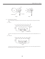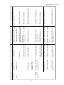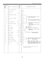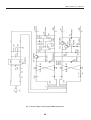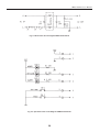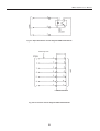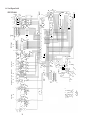
1
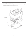
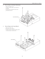
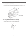
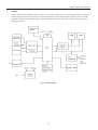
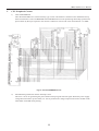
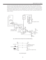
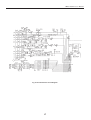
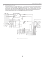
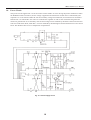
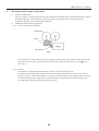
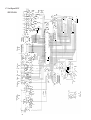
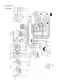
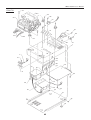
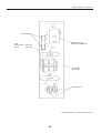
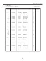
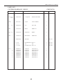
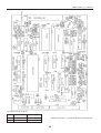
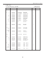
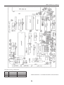
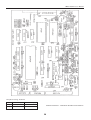
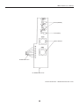
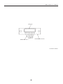
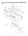
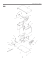
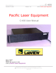
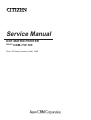
Service Manual
DOT MATRIX PRINTER
MODEL CBM-710/720
Rev.1.00 Newly issued on Mar, 1989
CONTENTS
Chapter 1. Printer Disassembly and Assembly ....................................................................................... 1
1
2
3
4
5
6
How to Remove Upper Cover and Rear Cover ............................................................................................
How to Remove The Printer Mechanism ......................................................................................................
How to Remove the Control Board ..............................................................................................................
How to Remove the Power Board and AC power Unit ................................................................................
How to Remove the Auto Cutter (CBM-720 only) .......................................................................................
How to Remove the Operation Panel and PE Sensor ...................................................................................
2
3
3
4
5
5
Chapter 2. Circuit Description ................................................................................................................. 6
1
2
3
4
5
6
7
8
9
10
Outline .......................................................................................................................................................... 7
CPU Peripheral Circuit ................................................................................................................................. 8
Printer Control Circuit ................................................................................................................................ 10
Cutter Control Circuit .................................................................................................................................. 11
Interface and Operation Panel ..................................................................................................................... 12
Paper End Sensor Circuit ............................................................................................................................ 13
Parallel Interface Circuit ............................................................................................................................. 14
Serial Interface Circuit ................................................................................................................................ 16
RS422A interface Circuit ............................................................................................................................ 18
Power Supply Circuit .................................................................................................................................. 19
Chapter 3. Auto Cutter ........................................................................................................................... 20
1
2
3
4
Maintenance and Handling .........................................................................................................................
Mechanism and Principle of Operation ......................................................................................................
Repairing and Troubleshooting ...................................................................................................................
Disassembly and Assembly ........................................................................................................................
21
22
24
26
Chapter 4. Circuit Diagram .................................................................................................................... 28
1
2
3
4
5
6
7
8
Power Supply Circuit ..................................................................................................................................
Noise Filter Circuit .....................................................................................................................................
Operation Panel Circuit ..............................................................................................................................
Paper End Sensor Circuit ............................................................................................................................
OP Junction Circuit .....................................................................................................................................
Parallel ........................................................................................................................................................
RS232C .......................................................................................................................................................
PS422A .......................................................................................................................................................
29
30
30
30
31
32
33
34
Chapter 5. Parts List ............................................................................................................................... 35
1
2
3
4
5
6
7
8
9
10
Exploded View ............................................................................................................................................
Block Diagram ............................................................................................................................................
Power Supply Unit ......................................................................................................................................
Noise Filter Unit .........................................................................................................................................
Control Board Unit: RS232C ......................................................................................................................
Control Board Unit: Parallel .......................................................................................................................
Control Board Unit: RS422A .....................................................................................................................
OP Panel/PE Detector/OP Junction Unit ....................................................................................................
Auto Cutter .................................................................................................................................................
Winder .........................................................................................................................................................
i
36
41
43
45
47
51
55
59
63
67
CBM-710/720 Service Manual
Chapter 1
Printer Disassebly and Assembly
1
CBM-710/720 Service Manual
1.
How to the Upper Cover and Rear Cover
1)
2)
Unfasten 4 screws (M3 x 6) as shown in the figure and lift the upper cover upward, while disconnecting the
connector.
Unfasten 4 screws (M3 x 6) at both sides and remove the rear cover.
Upper Cover
Connector
Rear Cover
2
CBM-710/720 Service Manual
2.
How to Remove the Printer Mechanism
• Remove the upper cover.
• Unfasten 2 screws (M3 x 14) as shown in
the figure.
• Lift the printer mechanism in the arrow
position for removal.
Printer Mechanism
3.
How to Remove the Control Board
• Remove the rear cover.
• Disconnect each connector.
• Unfasten 4 pieces of board mounting screws
for removal of the control board.
Control Board
3
CBM-710/720 Service Manual
4.
How to Remove the Power Board and AC Power Unit
1)
2)
How to Remove the Power Board
• Disconnect 2 connectors.
• Unfasten 2 screws (M3 x 8) and 2 tapping screws (M3 x 8).
• Remove the board, paying attention to the lead wire.
How to Remove the AC Power Unit
• Unfasten 2 inlet set screws (M3 x 10) and an earth wire mounting screw (M4 x 6).
• Unfasten 2 noise filter plate mounting screws (M3 x 6).
• Unfasten 4 power transformer mounting screws (M4 x 6).
• Disconnect the connector at the secondary side of the power transformer and take away the entire unit.
Power Transformer
Noise Filter Plate
Inlet
4
Power Board
CBM-710/720 Service Manual
5.
How to Remove the Auto Cutter Unit (720)
• Remove the printer mechanism from the main body.
• Remove 2 E3’s as shown in the figure.
• Pull out the shaft in the arrow direction for removal of the auto cutter unit. (Note that 2 spacers come off at the
same time).
Auto Cutter Unit
Spacer
Printer Mechanism
6.
How to Remove the Operation Panel Board and PE Sensor Board
• Remove the upper cover and unfasten 2 tapping screws for removal of the operation panel board.
• Remove the printer mechanism and unfasten a screw for removal of the PE sensor board assembled with the PE
sensor holder. To remove the board only, remove the lug of the PE sensor holder.
Lug
5
CBM-710/720 Service Manual
Chapter 2
Circuit Description
6
CBM-710/720 Service Manual
1.
Outline
A block diagram of this printer is shown in Fig. 1-1. It consists of the control circuit centered around CPU, ROM,
RAM and peripheral circuits, interface circuit for interfacing with each host computer, operator panel circuit for
operating switch input and LED display, printer mechanism, auto cutter, and power circuit for furnishing power
supply to each part.
Fig. 1-1 Block Diagram
7
CBM-710/720 Service Manual
2.
CPU Peripheral Circuits
1)
CPU and ROM/RAM
The CPU M50734SP has a external memory type. Lower 8-bit address is fetched via the A0/D0 bus line by
the 8-bit latch LS373. The 128-KB ROM and 64-KB RAM are used for performing the backup operation for
power failure by the super capacitor. The ceramic oscillator is used as CPU clock and transmits 7.37 MHz.
Fig. 2-1 CPU and ROM/RAM Circuit
2)
Initial Resetting and Power Failure Interrupt Circuit
The IC12 is an IC for generating the power failure interrupt signal and reset signal. When the power supply
voltage decreased due to power failure, etc. this IC performs the voltage inspection and stores all data in the
CPU buffer into RAM while printing.
8
CBM-710/720 Service Manual
As can be seen in the timing chart, it detects that Vcc decreased up to about 4.5 V for power failure and
generates the power failure interrupt signal and sends it to CPU. Upon receipt of the signal, CPU transmits
the data in its buffer to RAM. This processing is done within about 200 µs. After about 1 ms, the reset signal
is generated at IC12 and given to CPU, etc., causing all circuits to reset for prevention of explosive running.
When the power supply is turned on, reset is released after Vcc increases up to 4.5 V or more and then initial
setting is performed. The WD terminal of CPU is called “Watch Dog”, which is the output terminal used for
explosive running.
Super Capacitor 0.047F
External Reset Input
(To interface circuit)
Fig. 2-2 Power Failure Interrupt Circuit and Initial Resetting
4.5V
4.5V
Vcc (5V)
Power failure interrupt
signal generated
INT
(Power Failure Interrupt)
Reset
About 1ms (Data stored)
About 1ms
Fig. 2-3 Timing Chart
9
CBM-710/720 Service Manual
3.
Printer Control Circuit
1)
2)
3)
Printer
CN6
Winder
Operation Panel
Printer
4)
5)
When L is output to the CPU port P31, the motor rotates and a timing pulse appears at the DP terminal of
CN5.
After rotation of the motor, printing starts in timing at which the port P34 is changed into L from H by the
home pulse of the printer.
In 9 ports of CPU output ports P20 to 27 and P30, the L pulse is output to the necessary port. Electricity is
applied once to the DOT solenoid for two timing pulses and characters are printed.
The paper is fed when the CPU port P33 becomes L in the specified timing.
Color is changed when the CPU port P32 becomes L in the specified timing.
Fig. 3-1. Printer Control Circuit
10
CBM-710/720 Service Manual
4.
Cutter Control Circuit
Cutter Side
X
Y
S
Fig. 4-1 Cutter Control Circuit
The cutter control circuit is as shown in Fig. 4-1. In the cutter side, M indicates the motor and S the home switch.
The motor can make forward and reverse rotation by controlling X and Y inputs of the control circuit as shown in
the table below.
Normal Reverse
Stop
Stop
X
H
L
L
H
Y
L
H
L
H
The timing chart is provided in Fig. 4-2. The rising of S when the motor makes forward rotation is the home
position, where the motor stops. For full cut, the blade returns to the home position with only forward rotation of
the motor after turn-around. For partial cut, on the way of cut after forward rotation of the motor, make reverse
rotation to return the blade. Then stop the blade at the home position by making forward rotation again.
1) Full Cut
2) Partial Cut
1 mS
X
X
Y
Y
S
S
1 mS
15 mS
Fig. 4-2 Timing Chart
11
CBM-710/720 Service Manual
5.
Interface with Operation Panel
As shown in Fig. 5-1, the operation panel circuit has the on-line switch and line feed switch. Each switch is
connected to CPU input ports and each LED is connected through the driver to CPU output ports.
Control circuit
Operation Panel Circuit
Vcc
LED1
POWER
R1
LED2
CPU
ON-LINE
P04
R2
LED3
ALARM
P05
R3
SW1
ON-LINE
SW2
FEED
P35
P36
Fig. 5-1 Operation Panel Circuit
12
CBM-710/720 Service Manual
6.
Paper End Sensor Circuit
Fig. 6-1 shows the paper end sensor circuit. The reflection type photo-interrupter is used as a sensor. When some
paper is still left, the light reflected by paper strikes upon the photo-transistor; thus, the collector of the phototransistor is L. When paper becomes short, no light is reflected, causing the collector to go H. As a result, the CPU
input port P40 becomes H, going into the paper end state.
Control Circuit
Vcc
CPU
Paper End Sensor
PHI 1
R15
R12
R13
C11
Tr3
R14
Fig. 6-1 Paper End Sensor Circuit
13
P40
CBM-710/720 Service Manual
7.
Parallel Interface Circuit
This circuit conforms to the standard interface. Description will be made for each signal of interface connector as
follows. Fig. 7-1 shows the data input and print timing chart and Fig. 7-2 the parallel interface circuit diagram.
DATA (D1~D8) : 8-bit parallel signal (Positive logic)
STB
: Strobe signal for reading 8-bit data (Negative logic)
RESET
: Signal for resetting the printer (Negative logic)
ACK
: Data request signal to be output at the end of BUSY signal (Negative logic)
BUSY
: Signal for indicating if the printer is in the busy state; it goes into the busy state for H. (Positive
logic)
FAULT
: Signal to be output when the printer is in the abnormal state; at this time all control circuits in
the printer stop. (Negative logic)
PE
: Signal to be output when the print paper becomes short (Positive logic)
FG
: Frame ground
Fig. 7-1 Data Input and Print Timing Chart
14
CN2
CN3
16P
RA5
12-33kΩ
IC137406
IC10
7406
IC1
50734SP
R15
33k
Vcc
CBM-710/720 Service Manual
Fig. 7-2. Parallel Interface Circuit
15
CBM-710/720 Service Manual
8.
Serial Interface Circuit
As the serial interface specification, RS-232C and 20 mA current loop can be switched by the slide switch. It can
be switched by the user although fixed by setting at delivery time.
1)
RS-232C
By using MAX232C for data receiving (RD), data transmitting and BUSY (DTR), data is transmitted and
received at level of RS-232C. The baud rates of 110 to 9600 bps can be selected by switching the DIP
switch.
2)
20 mA Current Loop
The photo coupler is used for transmitting and receiving. The photo coupler LED is used for receiving data
and the photo transistor for transmitting data.
3)
DIP Switch Reading
The baud rate, word length, parity check, parity condition are set by the DTP switch.
4)
Positive/Negative Power Supply for RS-232C
±12 V power supply is required for obtaining RS-232C voltage level. In this printer, however, as IC
MAX232C for interface is used, ±12 V is generated at the power circuit built in IC. Thus, no other power
supply is required.
The serial interface circuit diagram is shown in Fig. 8-1.
16
CBM-710/720 Service Manual
Fig. 8-1 Serial Interface Circuit Diagram
17
CBM-710/720 Service Manual
9.
RS422A Interface Circuit
The RS422A interface circuit diagram is shown in Fig. 9-1. As can be seen in the figure, when TXD CONTROL is
L, the line driver IC14 becomes enable, going into the ready-to-receive state. At this time, the line receiver IC15
becomes disable. When TXD CONTROL is H, IC14 becomes disable, while IC15 becomes enable, going into the
ready-to-receive state. Communication is actually made through 2 lines although usually done through 4 lines
(including GND FG). These 2 lines are used for both transmitting and receiving of data.
TXD CONTROL
TXD
RXD
Fig. 9-1 RS422A Interface Circuit
18
CBM-710/720 Service Manual
10.
Power Circuit
This power circuit supplies DC 5 V for the control circuit and DC 24 V for driving the printer mechanism. When
the POWER switch is turned on, the AC voltage is applied to the transformer T after noise is eliminated by the
capacitors C1 to C4 and noise filter NF. For the secondary voltage of transformer, all waveforms are rectified at
both the DC 5 V side and DC 24 V side. IC1 indicates the regulator IC and Tr1 the current boosting transistor
which can generate DC 24 V constantly. The constant voltage can be obtained by the diode connected to the base
side of Tr3 and Zener diode, while DC 5 V can be obtained by the Darlington-connected transistor Tr2 for current
boost. The diode D5 also serves as temperature compensation.
Fig. 10-1. Power Supply Circuit
19
CBM-710/720 Service Manual
Chapter 3
Auto Cutter
20
CBM-710/720 Service Manual
1.
Maintenance and Handling
1)
Precautions for Handling
(1) Precautions for use
Do not cut the paper other than the specified recording paper or do not pull the recording paper on the
way of cutting; otherwise, resulting in damage of the blade section and reduction of service life.
(2) Precautions for storage
Store the unit avoiding dust, dirt, high temperature and high humidity.
2)
Cleaning
(1) Remove the dust of recording paper properly.
A good cleaning can be given by using the vacuum cleaner, etc.
(2) Use alcohol or benzine as a clearing solvent.
Thinner, trichlene, ketone, etc. may damage the plastic parts.
(3) After cleaning, lubricate as needed.
3)
Lubrication
Lubrication is not especially required within 150,000 cuts.
However, the blade operates slow, oil is used up for cleaning, and disassembly, assembly and replacement
are made, lubrication should be required.
Gear pivot
Lock level shaft
Crank pin
Movable blade sliding section
Maltenp
"
Mo grease
"
21
Brushing
"
"
"
CBM-710/720 Service Manual
2.
Mechanism and Principle of Operation
1)
Outline of Mechanism
The AC-2 and AC-3 are designed as the DP-505 and DP-600 small dot printers and characterized by compact
and lightweight types. The mechanism of this unit consists of 4 blocks; frame, power transmission
mechanism, detector, and movable blade mechanism.
2) Mechanism and Principle of Operation
2)-1 Power transmission mechanism
Cutter Gear
Worm
Motor Gear
Fig. 1
The reduction gear train of this auto cutter is composed of the motor gear mounted onto the motor shaft,
worn, and two cutter gears. One rotation of the motor gear rotates the cutter gear by 7/520 (
(See. Fig. 1.)
2)-2
1/74)
Detector
The detector is composed of the mechanism contract switch and cutter gear cam.
This detector detects the home position of the movable blade for partial cut (see Fig. 2), turn-around
position (see Fig. 3) and returned blade. It is turned on when the blade is at the home position and turned
off when the blade returns. The position where the detector is turned off from on after starting of the
movable blade is the turn-around position for partial cut.
22
CBM-710/720 Service Manual
Cam
Switch
Cutter Gear
Fig. 2
Fig. 3
2)-3
Movable blade mechanism
The movable blade is changed into a linear motion by the crank pins and starts cutting the recording
paper.
(1) Full cut
Blade
Fig. 4
Crank Pin
At full cut, the crank pins turn one time and return to the home position. The movable blade moves 12
mm.
(2) Partial cut
Fig. 5
At partial cut, the crank pins go into reverse at the moment they receive the switch signal and return to
the home position. The movable blade moves 9 mm.
23
CBM-710/720 Service Manual
3.
Repairing (Troubleshooting)
For troubleshooting, the repairing method will be explained by classifying the items as shown below.
Make sure of the cause according to the items and find out the trouble portions for repairing.
(1) Phenomenon ----------------- Find out the phenomenon of trouble from this column.
(2) Condition --------------------- Even in the same faulty phenomenon, the trouble condition may be different.
Check it, comparing with the content of this column.
(3) Cause -------------------------- The causes are listed on the basis of the trouble condition. Find out which cause is
applied.
(4) Check Point and Method --- The check method to find out the cause if described.
(5) Troubleshooting ------------- Repair the faulty portions according to the method described in this column.
24
2. The recording
paper cannot
be cut.
1. The motor
does not
rotate.
Phenomenon
Cause
25
1. Deformation of the cutter cover
2. Clogging of paper wastes or oil
shortage of the blade sliding
section
1. Damage or abrasion of the
movable blade
• Full cut is normal
• In partial cut, four uncut
portions or more remain
• The blade does not cut
well
• Dismount the movable blade to
check its edge.
• Detach the cutter cover to check its
warping, etc.
• Detach the cutter cover to check the
paper dust.
• Measure the thickness of the
recording paper.
(0.1 mm or less).
2. Entrance of foreign matters into • Check the paper passage.
the passage of recording paper
• Check the switch output with a
tester, etc.
1. Inappropriate recording paper
1. Detecting switch failure
• Make sure that the input power
supply is furnished. Check the both
terminals of the motor with the
tester, etc.
• Apply the rated voltage to the both
terminals of the motor and check if
the motor rates.
• Detach the cutter cover to check the
movable section.
Check Point and Method
• The blade returns on the
way though it attempts
to cut the paper.
• The motor operates
temporarily and stops
when the rotation
command is entered.
3. Lock due to entrance of foreign
matters into the rotation section
2. Motor failure
• The motor does not
1. Abnormality in input power
rotate even if the rotation
supply for motor
command is entered.
Condition
• Replace the blade if damaged or worn.
• Replace the cover if deformed.
• Eliminate the paper dust and lubricate.
• Eliminate the foreign matters.
• Use the specified recording paper.
• Replace the switch if an abnormality is
found.
• Eliminate the foreign matters.
• Replace the motor if not rotate.
• If the voltage is out of rating, correct the
power supply circuit.
Troubleshooting
CBM-710/720 Service Manual
CBM-710/720 Service Manual
4.
Disassembly/Assembly
1)
Disassembling Procedure
Perform the disassembly in a reverse manner of the assembling procedure.
2)
Assembling Procedure
Perform the assembly according to the assembling procedure as shown in the separate table. Numbers in
Exploded View at the end of this chapter are used as drawing numbers.
26
CBM-710/720 Service Manual
27
CBM-710/720 Service Manual
Chapter 4
Circuit Diagram
28
CBM-710/720 Service Manual
Fig. 4-1. Power Supply Circuit Diagram CBM710/720-001-00
29
CBM-710/720 Service Manual
Fig. 4-2. Noise Filter Circuit Diagram CBM710/720-002-00
Fig. 4-3. Operation Panel circuit Diagram CBM710/720-003-00
30
CBM-710/720 Service Manual
Fig. 4-4. Paper End Sensor Circuit Diagram CBM710/720-004-00
Cord Assy CA5
PC Board PC710-06
Fig. 4-5. OP Junction Circuit Diagram CBM 710/720-005-00
31
4-6. Circuit Diagram: Parallel
(PE)
2 3 1 CN9
Vcc
CBM710/720-006-00
CN3
16P
1
4
6
5
2
7
3
13, 18
12
10
11
32
1
31
2
3
4
5
6
7
8
9
14, 16, 30
33, 19-29
17
16
15
14
13
12
11
10
9
8
Vcc
12
RA5
12-33kΩ
10
4
1
13
10
3
8
9
13
2
12
13
13
C20
471
00
01
02
03
04
05
06
07
GND
101RH C9
x2
6
C103
222
1A4 1Y4
1A3 1Y3
1A2 1Y2
1A1 1Y1
2A4 2Y4
2A3 2Y3
2A2 2Y2
2Y1 2Y1
10 2G
1
Vcc
Printer
CN4
17P
1, 8, 9, 10
15
Winder Ope. Panel
Printer
2
CN5
9P
1
2
3
4
5
SOL
SOL
SOL
SOL
SOL
SOL
SOL
SOL
SOL
RA3
C12
102
7P
CN7
2
1
2P
5
1
Vcc 9
R104
3.3K
C16 471
C17 471
4
10
8
04 I4
R23
4.7K
R22
4.7K
Tr7
2SD809(1)
Cutter
11
11
8
Tr10
2SB731
R29
4.7K
Tr11
2SD809(1)
4 12
E2
6 E1
1
13 1Q 1D 15
4D
4Q
5
7
11 2Q 2D 9
3Q 3D
IC5
LS375
R19 10K
R20 22K
32
11
27 27
Vcc
13
15
13
E 2B
2YA 2A
16
12
8
IC
LS11
9
C8
471
IC7
1/2LS139
3
9
18
3
16
5
14
7
12
1
1Q
2AY
1A1
2Y4
1Y2
2Y3
1Y3
2Y2
1Y4
N
J1
C
28
C19
104
11
12
13
15
16
17
18
19
26
4
J2
5
19
2Q 11
2AY
2
1A1 17
2A4 4
1A2 15
2A3
6
1A3 13
2A2 8
1A4
IC5
LS240
Vcc
1
2
3
4
5
6
7
8
RA1
8-10K
C
C101
471
R7
3.3K
5
12
– 6
R9
10K
R8
100
+
0.047F
C7
N
R11
10K
B
R6
47K
+
7
Tr1 2SA1175
R10
62K
Vcc
C5
473
Vcc
Vcc Tr2
R3
2SC2785
1K
R5
3
+
3.3K
12 2 Vcc
1
–
R4
2.2K
IC12
µPC393
R1
1.5K(F)
R2
2.7K(F)
C5
1µ
ZD1
RD3.0EL1
DS1
2P
10
Vcc
BZ
VP
1
10
2
5
C4 35V 47µ
Vcc
C3
104
10K
R28
22K
11
10
9
8
7
6
5
4
3
25
24
21
23
2
Vcc
20
S1
A0
1
V0
2
3
4
D0
5
1
6
2
7
3
8
4
9
5
10
6
11
7
12
CE W S2
1
Vcc
5
Tr8
2SC2785 x 2
R25
Tr9
C18
103
2
1Q
8Q 19
2Q 5
7Q 16
3Q 6
6Q 15
4Q 9
5Q 13
0Q
11
10 10
11
8
9 7
8
11
8
9
8
R26 10K
Vcc
R101 1K
1D
8D
2D
7D
3D
14
6D
8 6D
13 5D
E
2
10K
R30
4.7K
7
IC4
LS373
3
18
4
17
7
4
6
6
1.8
12
VP VP
R31
10K
3
4
11
5
IC
µPD4464C
20
Vcc
A0 CE 1
1
27
2
3
4
11
5 D0
12
6
1 13
7
2 15
8
3 16
9
4
10 5 17
11 6 18
12 7 19
13 CE
22
Tr4
2SC2785 x 2
R18
R21
22K
2
11
STA403A
(1/4)
Tr5
4P
RA3
9-10KΩ
VP VP
Tr6
2SB731
VP
22
23
24
25
26
27
28
33
34
35
36
RA4 1K
R24
10K
CN8
13
14
15
16
17
18
19
20
21
4
A0 Y0
A1 Y1
Y2
Y3
3
30
31
XIN
XOUT
P00
ICI
1
2 50734SP
3
58
4
AD0 57
5
1 56
6
2 55
3 54
7
4 53
5 52
P10
6 51
1
7
2
49
3
ALE
4
48
A8 47
5
9 46
6
10 45
7
11 44
12 43
P20
13 42
1
14 41
2
15
3
4
5
6
7
P30
1
2
3
4
38
5
RD 39
6
WR 59
7
WD 29
P40
RESET
1
2
3
3
10
6
C102
473
5
6
7
8
9
10
11
12
5
3
Tr103
C2785
9
4
NC
Vcc
103
VP
1
8
R103
3.3K
VP
62
63
1
2
3
Vcc
1
8
Tr102
C2785
Vcc C15
102
12
16
16
18
3
5
7
9
Vcc
R102
3.3K
C14
60
61
10
19
Tr101
C2785
C13
102
11
10
I1 6
2 9
3 10
4 12
5 14
6 16
7 18
8 20
9
IC8LS04
15, 13
22
19, TAB
RA4
TA2STA403A 4-1KΩ
MOTOR
3
2
2
01 I1
CCSOL
5
4
8
2 2
7
6
LFSOL
3 3
6
Vcc
IC11 741S14
R17 100
6
1
5
4
6
7
2
1
3 O1
7 2
9 3
11 4
15 5
17 6
21 7
23 8
9
VP
7
8
9
CN5
1
2
3
4
5
6
7
8
9
R14
33K
R161M
10
9
8
7
6
5
4
3
25
24
21
23
2
26
R12
C11 180
103
IC7
1/2LS139
2
8
RA2 Vcc
9-10KΩ
TA1
HA13408
2
14
6
13
7
12
4
11
5
3
10
IC14
LS240
18
6
4
2
17
15
13
11
5
13
9
RA .6
8-1KΩ
FG
C10
OSC1737
Vcc
R13
68K
Tr3
2SC2758
11
13
3P
IC2 27128
13
Vcc
Vcc
IC137406
+5V
PE
ACK→
BUSY
FAULT
STB
RESET
10
R15
3.3K
R27 22K
3.4
L1
L2
C2
16V 100µ
C1
104
1
2
CN1
5P
Power
CN2
IC10
7406
C103 Vcc
233
IC14 JC15
R43
R33
CN2 CN3
10K
MAX232
3.3K
14
FAULT
11
6
14
14
12
12
13
PE
7
11
RESET
11
10 9
8
R3410K
8
13
14
23
C. BUSY R 12 2/1PHCI 2
5
Tr12 C2785
13
01
4
3
Vcc
13
1
C. BUSY
15
14
R56
11
R37
220
10K
R. BUSY
10
14
13
20
1/2PHCI 10
Tr13 C2785
4
CBM710/720-007-00
22
2
18
3
7
1
Printer
11
GNC
SOL
SOL
SOL
SOL
SOL
SOL
SOL
SOL
SOL
VP
Printer
Winder Ope. Panel
CN6
7P
CN7
12
RA5 8-10
RA3
9-10KΩ
1
4
8
8
3
5
C102
473
Tr6
2SB731
6
8
2
10
10
9
11
7
VP
Tr11
2SD809(1)
R29
4.7K
Tr5
R21
22K
11
1
27
10
9
8
7
6
5
4
3
25
24
21
23
2
11
12
13
15
16
17
18
19
Vcc
20
S1
A0
1
2 V0
3
4
5 D0
1
6
2
7
3
8
4
9
10 5
11 6
12 7
CE W S2
27
N
J1
C
28
C19
104
11
12
13
15
16
17
18
19
27 26
1
Vcc
13
15
13
E 2B
2Y0 2A
16
C8
471
8
IC6
LS375
Vcc
3
4
9
J2
Tr1 2SA1175
1
9
18
3
16
5
14
7
12
1Q
2Y1
1Y1
2Y4
1Y2
2Y3
1Y3
2Y2
1Y4
19
2Q
2A1
1A1
2A4
1A2
2A3
1A3
2A2
1A4
IC5
LS240
Vcc
1
2
3
4
5
6
7
8
11
2
17
4
15
6
13
8
RA1
8-10K
C
C101
471
R7
3.3K
5
+
7
12
– 6
IC12
µPC393
R10
62K
R8
100
R9
10K
+
C7
N
0.047F
R11
10K
5
Vcc
9
4 12
E1 E2 1
1Q 1D 15
4Q 4D 7
2Q 2D 9
3Q 3D
12
8
IC
LS11
IC7
1/2LS139
5
R19 10K
R20 22K
Vcc
B
Vcc Tr2
R3
2SC2785
1K
R5
+ 3
3.3K
12 2 Vcc
1
–
C6
C5
473
R4
1µ
2.2K
R6
47K
R1
1.5K(F)
R2
2.7K(F)
ZD1
RD3.0EL1
DS1
2P
10K
R26 10K
10
Vcc
1
VP
5
10
BZ
2
C4 35V 47µ
Vcc
C3
104
Tr8
2SC2785 x 2
R25
Tr9
R28
22K
11
Vcc
22
1Q 2
8Q 19
2Q 5
7Q 16
3Q 6
6Q 15
9
4Q
5Q 13
0Q
11
8
3
13
5
11
10K
Vcc
R101 1K
C18
103
IC
µPD4464C
IC2 27128
R18
VP VP
R31
R30
10K
4.7K
Tr10
2SB731
8
8
8
Tr7
2SD809(1)
11
4
RA4 1K
STA403A
(1/4)
VP
VP VP
R24
R23
Tr4
10K
4.7K 2SC2785 x 2
04 I4
1D
8D
2D
7D
3D
14
6D
8
13 4D
5D
E
12
3
R22
4.7K
CN8
11
Vcc 9
R104
3.3K
6
9
11
1
10
IC4
LS373
3
18
4
17
7
8
11
5
10
VP
11
3
Tr103
C2785
R12
180
C11
103
IC7
1/2LS139
2
4
A0 Y0 5
A1 Y1 6
3
Y2
7
Y3
1.8
20
A0CE
1
2
3
4
5 D0
1
6
2
7
3
8
4
9
10 5
11 6
12 7
13 CE
3
RA3
R103
3.3K
103
4
R161M
31
30
XIN
XOUT
P00
1
ICI
2 50734SP
3
4
AD0 58
57
1 56
5
2 55
6
3 54
7
4 53
5 52
P10
6 51
1
7
2
3
49
ALE
4
A8 48
5
9 47
6
10 46
7
11 45
12 44
P20
43
13 42
1
14 41
2
15
3
4
5
6
7
P30
1
2
3
4
5
38
RD 39
6
WR 59
7
WD 29
P40
RESET
1
10
9
8
7
6
5
4
3
25
24
21
23
2
26
22
23
24
25
26
27
28
33
34
35
36 2
Vcc
6
C2785
C16 471
C17 471
33
5
6
7
8
9
10
11
12
RA2 9-10KΩ
R102
3.3K
Tr102
C2785
C15
3
4
60
61
62
63
1
2
3
Vcc
Vcc102
2
101RH C9
C10
x2
OSC1737
13
14
15
16
17
18
19
20
21
8
R14
33K
Vcc
DS2
Vcc
IC11 741S14
C14
4P
1
4
4-1KΩ 2
3
2
01 I1
5
4
2 2
7
6
3 3
C13
102
2P
13
Vcc
R13
68K
Tr3
2SC2753
+ C21
– C22µ
+ C22
– 22µ
IC8LS04
C12
102
2
1
2
13
R38
10K
(PE)
CN9
2 3 1
R15
3.3K
10
Vcc
8 R40 1K
R35 10K
13
12 CL
13
7
R41 100
C20
103 RS
RC837
SW1-2
22
THC1
1
Cutter
14
8
Vcc
12
Vcc
R17 100
7
8
9
1
5
4
6
7
2
13
TA2STA403A RA4
MOTOR
CCSOL
Vcc
9P
6
15
R32
3.3K Vcc
Vcc C2310µ
15, 13
19, TAB
LFSOL
CN5
2/1PHCI
1
4 HA13408
3 O1 I1 6
7 2 2 8
9 3 3 10
11 4 4 12
15 5 5 14
17 6 6 16
21 7 7 18
23 8 8 20
9 9
1
2
3
4
5
6
7
8
9
15
1
2
3
4
5
6
15
8
14
R39 220
11
9
Vcc
3
14
R42 100
D3
C. RDR
R. RXD
FG
1, 8, 9, 10
2
9
IC14
IC15
1 C1 +
16
16
1
Vµ C1 +
3 C1 – Vµ V
2
C1 – 3
V+
V+
+
C2 +
C27 47µ
4 C2
V– C2 – 4
C2 – V–
5
6
6
5
C24
Vcc
47µ
TA1
2
C25 +
C25µ –
C26 +
22µ –
CN4
17P
12
SW1-1
CPD
13
16
14
6
13
7
12
4
11
5
3
9
16
D2
CSOR
TxD
Vcc
R27 22K
L1
L2
C2
16V 100µ
C1
104
3.4
CN1
1
5P
2
Power
4-7. Circuit Diagram: RS232C
CN2
CBM710/720-008-00
3
1
CN3
1
RD
R32
12
10
18
IC14 SN75113N ( Vcc
60.8 )
9
13
3
SD
R33
10
12
6
14
R38 4.7K
R37 4.7K
C21
2
2
1
2
3
13
10
Tr3
2SC2758
4
101RH C9
C10
x2
OSC1737
R34
4.7K
4
Vcc
–
+
NC
R40
47K
Vcc
NC 60
61
62
63
1
2
3
4
DS2
Printer
Vcc
2
CN4
17P
14
6
13
7
12
4
11
5
3
SOL
SOL
SOL
SOL
SOL
SOL
SOL
SOL
SOL
1
2
3
4
5
6
7
8
9
1
3 01
7 2
9 3
11 4
15 5
17 6
21 7
23 8
9
VP
1, 8, 9, 10
MOTOR
CCSOL
LFSOL
Winder Ope. Panel
Printer
Vcc
CN5
9P
1
2
3
4
5
6
7P
CN7
2
1
2P
Cutter
8
4
8
6
8
Tr101
C2785
R102
3.3K
Tr102
C2785
R103
3.3K
103
C12
102
C13
102
C14
Tr103
C2785
3
5
C16 471
C17 471
4
6
VP
9
C102
473
04 I4
11
1
2
8
9
7
10
R23
4.7K
Tr10
2SB731
Tr11
2SD809(1)
R29
4.7K
C18
103
11
11
1D
8D
2D
7D
3D
14 6D
8 4D
13 5D
E
8
4
8
3
13
5
11
5
IC6
LS375
9
18
3
16
5
14
7
12
13
15
E 2B 13
2Y0 2A 16
1Q
2Y1
1Y1
2Y4
1Y2
2Y3
1Y3
2Y2
1Y4
N
27
J1
C
28
C19
104
11
12
13
15
16
17
18
19
27 26
1
1
1
15
7
9
11
12
13
15
16
17
18
19
CE
12
8
IC
LS11
C8
471
IC7
1/2LS139
9
20
S1
A0
1
2 V0
3
4
5 D0
1
6
2
7
3
8
4
9
10 5
11 6
12 7
CE W S2
10
9
8
7
6
5
4
3
25
24
21
23
2
1
27
Vcc
12
E1 E2
1Q 1D
4Q 4D
2Q 2D
3Q 3D
Vcc
22
1Q 2
8Q 19
2Q 5
7Q 16
3Q 6
6Q 15
4Q 9
5Q 12
0Q
11
Vcc
IC
µPD4464C
IC2 27128
3
9
2Q
2A1
1A1
2A4
1A2
2A3
1A3
2A2
1A4
IC5
LS240
19
Vcc
11
2
17
4
15
6
13
8
1
2
3
4
5
6
7
8
RA1
8-10K
R10
62K
Vcc
4
J2
5
C
C101
471
R7
3.3K
5
N
B
R6
47K
+
7
12
– 6
C5
473
Tr1 2SA1175
R9
10K
R8
100
0.047F
C7
R11
10K
Vcc
Vcc
Tr2
2SC2785
R5
3
+
3.3K
12
2
1
–
R1
1.5K(F)
R3
1K
Vcc
C5
1µ
R4
2.2K
IC12
µPC393
R2
2.7K(F)
ZD1
RD3.0EL1
DS1
2P
Tr4
2SC2785 x 2
R18
10K
R19 10K
R20 22K
Vcc
1
10K
R26 10K
10
BZ
VP
5
2
C4 35V 47µ
Vcc
Tr8
2SC2785 x 2
R25
Tr9
R28
22K
Vcc
R101 1K
IC4
LS373
3
18
4
17
7
A0 CE
1
2
3
4
5 D0
1
6
2
7
3
8
4
9
10 5
11 6
12 7
13
Vcc
10
VP VP
R31
R30
10K
4.7K
8
10
9
8
7
6
5
4
3
25
24
21
23
2
26
R12
180
C11
R14
103
33K
IC7
1/2LS139
2
A0 Y0 4
3 A1 Y1 5
6
Y2 7
Y3
1.8
11
8
11
RA4 1K
R22
4.7K
VP
34
6
STA403A
(1/4)
VP VP
Tr7
2SD809(1)
3
4
11
5
10 10
3
8
Tr6
2SB731
CN8
4
11
10
R161M
30
31
XIN
XOUT
P00
ICI
1
2 50734SP
3
58
4
AD0 57
5
1 56
6
2 55
3 54
7
4 53
5 52
P10
6 51
1
7
2
3
49
ALE
4
5
A8 48
6
9 47
7
10 46
11 45
12 44
P20
43
13 42
1
14 41
2
15
3
4
5
6
7
P30
1
2
3
4
5
38
RD
6
39
WR
7
59
WD 29
P40
RESET
1
2
3
Vcc
R13
68K
12
11
3
Vcc 9
R104
3.3K
102
Tr5
R21
22K
2
RA3
9-10KΩ
1
2
Vcc
R24
10K
4P
22
23
24
25
26
27
28
33
34
35
36
Vcc
IC11 741S14
VP
1
RA2 9-10KΩ
TA2STA403A RA4
4-1KΩ
3
2
01 I1
5
4
2 2
7
6
3 3
Vcc
CN5
13
14
15
16
17
18
19
20
21
RA3
7
8
9
1
5
4
6
7
2
RA2 8-10K
Vcc
22
R17 100
5
6
7
8
9
10
11
12
4 HA13408
6
8
10
12
14
16
18
20
IC8LS04
15, 13
19, TAB
15
2
TA1
I1
2
3
4
5
6
7
8
9
3P
20
10
3
(PE)
CN9
2 3 1
R15
3.3K
13
–
+
R38 4.7K
Vcc R39
47K
FG
5
11
GND
5
13
Vcc
R35 4.7K
18
IC15 SN75175N (Vcc
60.8.12)
101
13
11
15
Vcc
C20
13
10
R27 22K
C3
104
3.4
L1
L2
C2
16V 100µ
C1
104
CN1
1
5P
2
Power
4-8. Circuit Diagram: RS422A
CBM-710/720 Service Manual
Chapter 5
Parts List
35
CBM-710/720 Service Manual
PARTS LIST
1. Exploded View
Ref. No.
Parts No.
CBM-710/720
Description
Q’ty
Remarks
1
2
3
4
5
6
7
8-1
E 4002-230
E 4002-240
E 4035-620
E 6601-210
E 4000-520
E 4018-140
E 4000-530
E 4004-180
Chassis Sub Assy
Cover for PCB
Grounding Plate
Supporter for Printer
PE Detector unit
Spacer for PCB
Operation Panel Junction Unit
Inlet
NC-174-C
12
E 4000-510
E 4000-500
E 4000-515
Noise Filter Unit 120V
Noise Filter Unit 230V EMI Class A
Noise Filter Unit 230V EMI Class B
11
E 4023-040
NF PCB Holder
13
E 4001-740
Power Transformer
25-0091
1
115V
E 4001-745
Power Transformer
25-0092
1
only
220-240V
only
E 4018-160
E 4000-490
E
E 4024-040
E 4800-975
E 4800-980
E 4800-985
Supporter for PCB
Power Supply Unit
Control Board Unit
Connector Cover
Cord Assy
Cord Assy
Cord Assy
19
E 6601-220
Printer Stand
20-1
E 6600-780
E 6600-790
E 6600-800
E 6600-810
E 8000-010
Printer
Printer
Printer
Printer
Auto Cutter
DP610-DFC
DP612-DFC
DP617-DFC
DP614-DFC
AC-2
E 8000-
Auto Cutter
AC-2F
E 6202-800
E 6302-190
E 62010160
E 5200-070
Bottom Plate
Rubber Foot
Top Case
OP. Panel Overlay 1S
14
15
16
17
18-1
-2
-2
21
22
23
24
1
1
1
2
1
1
(1)
(1)
(1)
115V
220-240V
220-240V
1
2
CA 1
CA 2
CA 3
1
1
1
1
AW only
Validation
2
36
1
1
4
1
1
CBM720
only
CBM-710/720 Service Manual
PARTS LIST
Ref. No.
25
26-1
CBM-710/720
Parts No.
E 4000-530
E 6204-590
Description
Q’ty
Operation Panel Unit
Printer Cover
Remarks
1
CBM710
only
CBM720
only
CBM710
only
CBM720
only
Validation
-2
E 6204-600
Printer Cover (AC)
1
27-1
E 6204-700
Paper Cover
1
-2
E 6204-710
Paper Cover (AC)
1
-3
E 6204-720
Paper Cover (V)
1
30
31
32
33
34
35
37
38
S 3 X 6-S
S 3 X 10-S
SW 3 X 6
SBST 3 X 8
S3X6
S 3 X 10
SW 3 X 14
SWT 4 X 6
Pan Head Screw
Pan Head Screw
Pan Head Screw/W
Tapping Screw
Pan Head Screw
Pan Head Screw
Pan Head Screw/W
Pan Head Screw/TW
40
E 6100-530
AC Cord
(1)
115V
E 6200-535
AC Cord
(1)
only
220-240V
only
37
M3 x 6
M3 x 10
M3 x 6
M3 x 8
M3 x 6
M3 x 10
M3 x 14
M4 x 6
6
2
3
4
15
4
2
5
CBM-710/720 Service Manual
CBM-710,720
27-2
27-1
26-2
26-1
23
34
24
25
33
38
CBM-710/720 Service Manual
20-1
CBM-710
34
4
32
5
32
37
34
8-1
3
35
18-1
18-2
2
19
38
17
7
31
30
11
30
13
16
12
30
6
35
14
38
15
34
33
35
21
34
22
39
CBM-710/720 Service Manual
37
CBM-720
20-2
34
4
32
20-1
5
32
3
34
8-1
35
2
18-1
18-2
19
38
17
1
7
31
30
11
30
13
16
12
30
6
35
14
38
15
33
35
34
21
34
22
40
CBM-710/720 Service Manual
PARTS LIST
2. Block Diagram
Ref. No.
CA
CBM-710/720
Parts No.
Description
Q’ty
Remarks
E 6100-530
AC cord
25-0102
1
115V
E 6100-535
AC cord
25-0103
1
only
220-240V
only
E 4004-180
Inlet
NC-174C
1
E 4001-740
Power Transformer
25-0091
1
115V
E 4001-745
Power Transformer
25-0093
1
only
220-240V
only
1
2
3
4
E 4800-975
E 4800-980
E 4800-985
E 4800-990
Cord Assy
Cord Assy
Cord Assy
Cord Assy
CA 1
CA 2
CA 3
CA 4
1
1
1
1
5
7
8
E 4800-960
E 48000010
E 4800-970
Cord Assy
Cord Assy
Cord Assy
CA 5
CA 7
CA 8
1
1
1
41
CBM720
only
CBM-710/720 Service Manual
BLOCK DIAGRAM
42
CBM-710/720 Service Manual
PARTS LIST
4. Power Supply Unit
CBM-710/720
Ref. No.
Parts No.
IC
1
E 390-110
Regulator
M5231TL
1
TR
1
2
3
E 324-010
E 360-040
E 359-278
Transistor
Transistor
Transistor
2SB974L
2SD1310M1
2SC2785HF
1
1
1
1-4
6-9
5
E 400-130
Diode
GP-15B
8
E 400-010
Diode
1S1588
1
E 405-130
Zener Diode
RD5. 6EB2
1
1
1
1
1
1
D
ZD
Description
Q’ty
R
1
2
3
4
5
E 3331-041
E 3561-041
E 3203-100
E 3152-110
E 3821-041
Resistor
Resistor
Resistor
Resistor
Resistor
1/4W
1/4W
1/4W
1/4W
1/4W
C
1
2
3
4
5
6
7
E 2022-740
E 2110-170
E 2001-650
E 2033-750
E 2033-740
E 2010-020
E 2010-010
El. Capacitor
C. Capacitor
El. Capacitor
El. Capacitor
El. Capacitor
El. Capacitor
El. Capacitor
63PN-G2200A (25X30)
DD804B101K50
50MR-1
35MR-330
16MR-3300
16MR-10
16MR-100
1
1
1
1
1
1
1
13
E 4800-965
E 4800-970
Connector
Cord Assy
5273-04A
CA 8
1
1
E 4010-300
E 4019-100
Heat Sink
Insulation Sheet
25-0061
2067A-5051
1
2
E 4005-465
E 4006-220
Fuse
Fuse Holder
5MF-3A
UF-0033#01
1
2
S 3 x 8-S
S 3 x 6-S
Pan Head Screw M3 x 8
Pan Head Screw M3 x 6
CN
F
1
43
330 J
560 J
20K F
1.54K F
820 J
2
2
Remarks
TR 1,2
TR 1,2
CBM-710/720 Service Manual
INSULATOR
Screw M3x8/2
Screw M3x6/2
Cord assy
CA 8
D1 - D4, D6 - D9 : GP15B
D5 : 1S1588
ZD1 : RD5. 6EB2
PC BOARD
PC710-07A
PARTS POSITION : POWER SUPPLY UNIT
44
CBM-710/720 Service Manual
PARTS LIST
4. Noise Filter Unit
CBM-710/720
Ref. No.
Parts No.
SW
1
E 4003-495
Power Switch
SF-W101A-01BB
1
F
1
E 4005-470
Fuse
EAWK-500mA
1
E 4005-475
Fuse
5MF-1A
1
E 4006-220
Fuse Holder
UF-0033#01
2
E 4009-270
Noise Filter
PLA3021A
1
1,2
3,4
E 2310-010
E 2122-735
Film Capacitor CFX22E104M
C. Capacitor
DE7100F222MVA1-KC
2
2
3,4
E 2122-725
C. Capacitor
2
NF
C
Description
DE1410E222MACT4-KD
45
Q’ty
Remarks
220-240V
only
100, 115V
only
100, 115V
only
220-240V
only
CBM-710/720 Service Manual
FUSE HOLDER
POWER SWITCH
(MOUNTED ON BACK)
FUSE
EAWK-500mA : 220-240V
5MF-1A
: 100/115V
PC BOARD
PC710-08
C. CAPACITOR
PARTS POSITION : NOISE FILTER UNIT
46
CBM-710/720 Service Manual
PARTS LIST
5. Control Board Assy : RS232C
CBM-710/720
Ref. No.
Parts No.
IC
E 104-200
E 107-130
E 104-220
E 2010170
E 2010220
E 2010230
E 2010240
E 2010250
E 2010260
E 2010200
E 2010270
E 202-610
E 2010040
LSI (CPU)
LSI (PROM)
LSI (RAM)
IC (TTL)
IC (TTL)
IC (TTL)
IC (TTL)
IC (TTL)
IC (TTL)
IC (TTL)
IC (TTL)
IC
IC (CMOS)
M50734SP
M5L27128K
uPD4464C-15L
SN74LS373N
SN74LS240N
SN74LS375N
SN74LS139N
SN74LS04N
SN741S11N
SN7406N
SN74LS14N
uPC393C
MAX232CPE
1
1
1
1
1
1
1
1
1
1
1
1
2
1
2
E 390-100
E 390-120
Tr. Array
Tr. Array
HA13408
STA403A
1
1
1
2-5
8,9
12,13
101-103
6,10
7,11
E 319-117
E 359-278
Transistor
Transistor
2SA1175HF
2SC2785HF
1
11
E 327-030
E 360-020
Transistor
Transistor
2SB731L
2SD809(1)L
2
2
1
E 403-060
Zener Diode
RD3. 0EL1
1
1-3
E 400-010
Diode
IS1588
3
1
E 391-080
Photocupprer
PC837
1
1,5
2,3
4
E 3103-140
E 3103-170
E 3013-090
Re. Array
Re. Array
Re. Array
SR-8RA-10K
SR-9RA-10K
SR-4RB-1K
2
2
1
1
2
3
4
5
6
7
8, 13
9
10
11
12
14, 15
TA
TR
ZD
D
PHC
RA
Description
47
Q’ty
Remarks
CBM-710/720 Service Manual
PARTS LIST
CONTROL BOARD ASSY : RS232C
CBM-710/720
Ref. No.
Parts No.
Description
R
1
2
3,40,101
4
5,7,15
32,43
102-104
6
8,17,41
42
9,11,18
19,24-26
31,33-36
38
10
12
13
14
16
20,21
27,28
22,23
29,30
37,39
E 3152-100
E 3272-090
E 3102-041
E 3222-041
E 3332-041
Resistor
Resistor
Resistor
Resistor
Resistor
1/4W
1/4W
1/4W
1/4W
1/4W
1.5K
2.7K
1K
2.2K
3.3K
F
F
J
J
J
1
1
3
1
8
E 3473-041
E 3101-041
Resistor
Resistor
1/4W
1/4W
47K J
100 J
1
4
E 3103-041
Resistor
1/4W
10K J
13
E 3623-041
E 3181-041
E 3683-041
E 3333-041
E 3105-041
E 3223-041
Resistor
Resistor
Resistor
Resistor
Resistor
Resistor
1/4W
1/4W
1/4W
1/4W
1/4W
1/4W
62K
180
68K
33K
1M
22K
J
J
J
J
J
J
1
1
1
1
1
4
E 3472-041
Resistor
1/4W
4.7K J
4
E 3221-041
Resistor
1/4W
220
2
C 1,3,19
2
4
5
6,102
7
8,16
17,101
9,10
11,14
20
12,13
15
18
21,22
25,26
23
24,27
E 2104-330
E 2010-010
E 2047-640
E 2001-650
E 2310-220
E 2000-020
E 2147-060
C. Capacitor
El. Capacitor
El. Capacitor
El. Capacitor
My. Capacitor
El. Capacitor
C. Capacitor
DD306-63F104Z12
16MR-100
35MR-47
50MR-1
DMY21H473K
FS0H-473Z
DD804-63B471K50
3
1
1
1
2
1
4
E 2110-340
E 2110-270
C. Capacitor
C. Capacitor
DD107-63R101J50
DD806-63F103Z50
2
3
E 2110-380
C. Capacitor
DD804-63B102K50
3
E 2110-290
E 2022-500
C. Capacitor
El. Capacitor
DD806-63F103K50
16MR-22
1
4
E 2010-650
E 2047-615
El. Capacitor
El. Capacitor
50MR-10
16MR-47
1
2
48
Q’ty
J
Remarks
CBM-710/720 Service Manual
PARTS LIST
CONTROL BOARD ASSY : RS232C
CBM-710/720
Ref. No.
Parts No.
CP 1,5,8
11,13
E 2110-300
C. Capaciotr
DD306-63F104Z12
5
OSC
E 501-150
Crystal
CSA7.37MT40
1
E 4009-300
Coil
SN-3-200
2
E 7151-120
Buzzer
MEB-12-5
1
L
1,2
BZ
Description
Q’ty
Remarks
DS
1,2
E 5103-350
Dip Switch
KSD-8
2
SW
1
E 5104-330
Slide Switch
MMS A2-2
1
E 4010-290
Heat Sink
1
for TA 1
S3x8
N 3-1-N
S 3 x 10-S
Pan Head Screw M3 x 8
Nut
M3
Pan Heat Screw M3 x 10
2
2
1
for TA 1
for TA 1
for CN 2
E 4800-915
E 4800-920
E 4800-925
E 4800-930
E 4800-935
E 4800-940
E 4800-945
E 4800-950
Connector
Connector
Connector
Connector
Connector
Connector
Connector
Connector
1
1
1
1
1
1
1
1
CN
1
2
4
5
6
7
8
9
5267-05A-X
25KC0050-120
5267-17A-X
5267-09A-X
5267-07A-X
5268-02A-X
5267-04A-X
5267-03A-X
49
CBM-710/720 Service Manual
Jump Wire Setting : RS232C
with Back Up (B) without Back Up (N)
Jumper 1
Open
C-N Short
Jumper 2
C-B Short
C-N Short
PARTS POSITION : CONTROL BOARD UNIT RS232C
50
CBM-710/720 Service Manual
PARTS LIST
6. Control Board Assy : Parallel
CBM-710/720
Ref. No.
Parts No.
IC
1
2
3
4
5,14
6
7
8
9
10,13
11
12
E 104-200
E 107-130
E 104-220
E 2010170
E 2010220
E 2010230
E 2010240
E 2010250
E 2010260
E 2010200
E 2010270
E 202-610
LSI (CUP)
LSI (PROM)
LSI (RAM)
IC (TTL)
IC (TTL)
IC (TTL)
IC (TTL)
IC (TTL)
IC (TTL)
IC (TTL)
IC (TTL)
IC
M50734SP
M5L27128K
uPD4464C-15L
SN74LS373N
SN74LS240N
SN74LS375N
SN74LS139N
SN74LS04N
SN74LS11N
SN7406N
SN74LS14N
uPC393C
1
1
1
1
2
1
1
1
1
1
1
1
TA
1
2
E 390-100
E 390-120
Tr. Array
Tr. Array
HA13408
STA403A
1
1
1
2-5,8
9
101-103
6,10
7,11
E 319-117
E 359-278
Transistor
Transistor
2SA1175HF
2SC2785HF
1
9
E 327-030
E 360-020
Transistor
Transistor
2SB731L
2SD809(1)L
2
2
TR
Description
Q’ty
ZD
1
E 403-060
Zener Diode
RD3.0EL1
1
RA
1
2,3
4
5
6
E 3103-140
E 3103-170
E 3013-090
E 3332-120
E 3102-110
Re. Array
Re. Array
Re. Array
Re. Array
Re. Array
SR-8RA-10K
SR-9RA-10K
SR-4RB-1K
SR-12RA-3.3K
SR-10RA-1K
1
2
1
1
1
1
2
3,101
4
5,7,15
101-104
6
E 3152-100
E 3272-090
E 3102-041
E 3222-041
E 3332-041
Resistor
Resistor
Resistor
Resistor
Resistor
1/4W
1/4W
1/4W
1/4W
1/4W
F
F
J
J
J
1
1
2
1
6
E 3473-041
Resistor
1/4W
47K J
1
R
51
1.5K
2.7K
1K
2.2K
3.3K
Remarks
CBM-710/720 Service Manual
PARTS LIST
CONTROL BOARD ASSY : PARALLEL
CBM-710/720
Ref. No.
Parts No.
R
8,17
9,11,18
19,24-26
31
10
12
13
14
16
20,21
27,28
22,23
29,30
E 3101-041
E 3103-041
Resistor
Resistor
1/4W
1/4W
100 J
10K J
2
8
E 3623-041
E 3181-041
E 3683-041
E 3333-041
E 3105-041
E 3223-041
Resistor
Resistor
Resistor
Resistor
Resistor
Resistor
1/4W
1/4W
1/4W
1/4W
1/4W
1/4W
62K
180
68K
33K
1M
22K
J
J
J
J
J
J
1
1
1
1
1
4
E 3472-041
Resistor
1/4W
4.7K J
4
C 1,3,19
2
4
5
6,102
7
8,16,17
9,10
11,14
18
12,13
15
20,101
E 2104-330
E 2010-010
E 2047-640
E 2001-650
E 2310-220
E 2000-020
E 2147-060
E 2110-340
E 2110-270
C. Capacitor
El. Capacitor
El. Capacitor
El. Capacitor
My. Capacitor
El. Capacitor
C. Capacitor
C. Capacitor
C. Capacitor
DD306-63F104Z12
16MR-100
35MR-47
50MR-1
DMY21H473K
FSOH-473Z
DD804-63B471K50
DD107-63R101J50
DD806-63F103Z50
3
1
1
1
2
1
3
2
3
E 2110-380
C. Capacitor
DD804-63B102K50
3
E 2147-060
C. Capacitor
DD804-63B471K50
2
CP 1,5,8
10,12
E 2104-330
C. Capacitor
DD306-63F104Z12
5
OSC
E 501-150
Crystal
CSA7.37MT40
1
E 4009-300
Coil
SN-3-200
2
E 7151-120
Buzzer
MEB-12-5
1
L
BZ
1,2
Description
52
Q’ty
Remarks
CBM-710/720 Service Manual
PARTS LIST
CONTROL BOARD ASSY : PARALLEL
CBM-710/720
Ref. No.
Parts No.
DS
E 5103-350
Dip Switch
KSD-8
1
E 4010-290
S3x8
N 3-1-N
Heat Sink
Pan Head Screw
Nut
50-0032
M3 x 8
M3
1
2
2
E 4800-915
E 4800-895
E 4800-925
E 4800-930
E 4800-935
E 4800-940
E 4800-945
E 4800-950
Connector
Connector
Connector
Connector
Connector
Connector
Connector
Connector
5267-05A-X
MRD-36SB-130
5267-17A-X
5267-09A-X
5267-07A-X
5268-02A-X
5267-04A-X
5267-03A-X
1
1
1
1
1
1
1
1
CN
1
1
2
4
5
6
7
8
9
Description
53
Q’ty
Remarks
for TA 1
for TA 1
for TA 1
CBM-710/720 Service Manual
Jump Wire Setting : PARALLEL
with Back Up (B) without Back Up (N)
Jumper 1
Open
C-N Short
Jumper 2
C-B Short
C-N Short
PARTS POSITION : CONTROL BOARD UNIT PARALLEL
54
CBM-710/720 Service Manual
PARTS LIST
7. Control Board Assy : RS422A
CBM-710/720
Ref. No.
Parts No.
IC
1
2
3
4
5
6
7
8,13
9
10
11
12
14
15
E 104-200
E 107-140
E 104-220
E 2010170
E 2010220
E 2010230
E 2010240
E 2010250
E 2010260
E 2010200
E 2010270
E 202-610
E 202-620
E 202-630
LSI (CPU)
LSI (PROM)
LSI (RAM)
IC (TTL)
IC (TTL)
IC (TTL)
IC (TTL)
IC (TTL)
IC (TTL)
IC (TTL)
IC (TTL)
IC
IC (TTL)
IC (TTL)
M50734SP
M5L27128K
uPD4464C-15L
SN74LS373N
SN74LS240N
SN74LS375N
SN74LS139N
SN74LS04N
SN74LS11N
SN7406N
SN74LS14N
uPC393C
SN75113
SN75175
1
1
1
1
1
1
1
2
1
1
1
1
1
1
TA
1
2
E 390-100
E 390-120
Tr. Array
Tr. Array
HA13408
STA403A
1
1
1
2-5
8,9
101-103
6,10
7,11
E 319-117
E 359-278
Transistor
Transistor
2SA1175HF
2SC2785HF
1
9
E 327-030
E 360-020
Transistor
Transistor
2SB731L
2SD809(1)L
2
2
E 403-060
Zener Diode
RD3. 0EL1
1
1,5
2,3
4
E 3103-140
E 3103-170
E 3013-090
Re. Array
Re. Array
Re. Array
SR-8RA-10K
SR-9RA-10K
SR-4RB-1K
2
2
1
1
2
3,101
4
5,7,15
102-104
E 3152-100
E 3272-090
E 3102-041
E 3222-041
E 3332-041
Resistor
Resistor
Resistor
Resistor
Resistor
1/4W
1/4W
1/4W
1/4W
1/4W
TR
ZD
RA
R
Description
55
Q’ty
1.5K
2.7K
1K
2.2K
3.3K
F
F
J
J
J
1
1
2
1
6
Remarks
CBM-710/720 Service Manual
PARTS LIST
CONTROL BOARD ASSY : RS422A
CBM-710/720
Ref. No.
Parts No.
Description
R
6,35
38-40
8,17
9,11
18,19
24-26
31
10
12
13
14
16
20,21
27,28
22,23
29,30
34,36
37
32,33
E 3473-041
Resistor
1/4W
47K J
5
E 3101-041
E 3103-041
Resistor
Resistor
1/4W
1/4W
100 J
10K J
2
8
E 3623-041
E 3181-041
E 3683-041
E 3333-041
E 3105-041
E 3223-041
Resistor
Resistor
Resistor
Resistor
Resistor
Resistor
1/4W
1/4W
1/4W
1/4W
1/4W
1/4W
62K
180
68K
33K
1M
22K
J
J
J
J
J
J
1
1
1
1
1
4
E 3472-041
Resistor
1/4W
4.7K J
7
E 3100-041
Resistor
1/4W
10
2
C 1,3,19
2
4
5
6,102
7
8,16
17
9,10
11,14
18
12,13
15
20,21
101
E 2104-330
E 2010-010
E 2047-640
E 2001-650
E 2310-220
E 2000-020
E 2147-060
C. Capacitor
El. Capacitor
El. Capacitor
El. Capacitor
My. Capacitor
El. Capacitor
C. Capacitor
DD306-63F104Z12
16MR-100
35MR-47
50MR-1
DMY21H473K
FSOH-473Z
DD804-63B471K50
3
1
1
1
2
1
3
E 2110-340
E 2110-270
C. Capacitor
C. Capacitor
DD107-63R101J50
DD806-63F103Z50
2
3
E 2110-380
C. Capacitor
DD804-63B102K50
3
E 2110-330
C. Capacitor
DD804-63B101K50
3
CP 1,5,8
11,13
E 2110-300
C. Capacitor
DD306-63F104Z12
5
56
Q’ty
J
Remarks
CBM-710/720 Service Manual
PARTS LIST
Control Board Assy : RS422A
CBM-710/720
Ref. No.
Parts No.
OSC
1
E 501-150
Crystal
CSA7.37MT40
1
1,2
E 4009-300
Coil
SN-3-200
2
E 7151-120
Buzzer
MEB-12-5
1
E 5103-350
Dip Switch
KSD-8
2
E 4010-290
S3x8
N 3-1-N
Heat Sink
50-0032
Pan Head Screw M3 x 8
Nut
M3
1
2
2
E 4800-915
E 4800-955
E 4800-925
E 4800-930
E 4800-935
E 4800-940
E 4800-945
E 4800-950
Connector
Connector
Connector
Connector
Connector
Connector
Connector
Connector
1
1
1
1
1
1
1
1
E 4024-050
M 3 x 10
Connector Cover
Pan Head Screw M3 x 10
L
BZ
DS
CN
1,2
1
2
4
5
6
7
8
9
Description
5267-05A-X
JEY9S-1A1A-90
5267-17A-X
5267-09A-X
5267-07A-X
5268-02A-X
5267-04A-X
5267-03A-X
57
Q’ty
1
1
Remarks
for TA 1
for TA 1
for TA 1
CBM-710/720 Service Manual
Jump Wire Setting : RS422A
with Back Up (B) without Back Up (N)
Jumper 1
Open
C-N Short
Jumper 2
C-B Short
C-N Short
PARTS POSITION : CONTROL BOARD UNIT RS422A
58
CBM-710/720 Service Manual
PARTS LIST
8. OPERATION PANEL UNIT/PE DETECTOR UNIT/OPERATION PANEL JUNCTION UNIT
CBM-710/720
Ref. No.
Parts No.
Description
Q’ty
** OPERATION PANEL UNIT **
D
1,2
3
E 480-250
E 480-260
LED Lamp
LED Lamp
GL9NG22
GL9PR22
2
1
R
1,2
3
E 3221-041
E 3471-041
Resistor
Resistor
1/4W
1/4W
2
1
SW 1,2
E 5102-410
Tact Switch
SKH-KAA
2
CA
E 4800-960
Cord assy
CA 5
1
5
220 J
470 J
** PE DETECTOR UNIT**
PH
1
E 4000-520
E 391-090
E 6650-040
P.E. PCB Assy
Photointerrupter GP2S05
PE Holder
1
1
1
CA
7
E 48000010
Cord Assy
1
CA 7
** OPERATION PANEL JUNCTION UNIT **
CN
CA
12
5
E 4000-530
O.P. PCB Assy
E 4800-935
E 4800-960
Connector
Cord assy
1
5267-07A-X
CA 5
59
1
1
Remarks
CBM-710/720 Service Manual
LED (GREEN)
LED (RED)
TACT SWITCH
CORD ASSY CA 5
PC BOARD PC710-04
PARTS POSITION : OPERATION PANEL UNIT
60
CBM-710/720 Service Manual
PHOTOINTERRUPTER
GR2S05
PC BOARD PC710-05
CORD ASSY CA 7
PARTS POSITION : PE DETECTOR UNIT
61
CBM-710/720 Service Manual
5267-07A
PC BOARD PC710-06
CORD ASSY CA 5
OP Junction Block
62
CBM-710/720 Service Manual
PARTS LIST
9. Auto Cutter
AC-2/AC-3
Q’ty
Ref. No.
1
2
3
4
5
6
7
8
9
10
10-1
10-2
10-3
10-4
11
12
13
14
15
16
17
18
19
20
21
22
Parts No.
Description
AC-2 AC-3
E 8010-010
E 8010-020
E 8011-010
S 2.6 x 8
E 8012-010
E 8013-010
E3
E 8014-010
E 8015-010
E 2.5
Frame Assy (2)
Frame Assy (3)
Paper Guid (2)
Pan Head Screw
Lock Lever Sssy R
Lock Lever Assy L
E Ring
Lock Lever Spring
Cutter Gear Assy
E Ring
E 8016-010
E 8016-020
E 8017-010
E 8017-020
E 8018-010
E 8019-010
E 48000070
E 8020-010
S 2.6 x 5-s
SW 2 x 8
E 4031-060
E 8021-010
E 8022-010
E 8030-010
E 8023-010
E 8024-010
E 8030-020
E 8025-010
E 8026-010
E 8027-010
E 8026-020
E 8027-020
Motor Assy (DC24V, 50mA)
Motor Assy (DC12V, 65mA)
Motor (DH515, DC24v, 50mA)
Motor (DH416, DC12V, 65mA)
Limit Switch
D2F-01FL
Motor Gear
Cord Assy (25-0080)
Worm Gear Assy
Pan Head Screw
M2.5 x 6
Pan Head Screw/W
M2 x 8
Wire Band
T18S
Blade Spring
Guide Plate
Blade
Blade Cover
Frame Shift
Blade (Full Cut Type)
Spacer
Hook R
Bracket R
Hook L
Bracket L
63
Remarks
1
M2.6 x 8
3
2.5
1
4
1
1
7
2
2
2
1
1
4
2
2
2
1
1
1
1
1
1
1
2
2
1
2
1
1
1
1
1
2
1
1
1
1
1
1
4
2
1
2
1
1
1
1
1
1
DC 24V
DC 12V
CBM-710/720 Service Manual
AC-2
12
3
1
20
6
7
10-2
19
15
6
5
16
4
2
13
10
10-3
10-1
8
11
9
17
14
18
21, 22
6
3
64
CBM-710/720 Service Manual
12
AC-3
3
10-4
1
15
10-2
16
2
13
10-3
10
10-1
8
11
9
17
14
18
21, 22
6
3
12
65
CBM-710/720 Service Manual
PARTS LIST
10. Winder
AW-2
Ref. No.
Parts No.
Description
1
E 8500-010
AW Frame Assy
1
2
E 8510-010
Motor Assy (DC24V, 50mA)
1
2-1
E 8017-010
Motor (DH515, DC24V, 50mA)
1
-2
E 8512-010
Motor Gear
1
-3
E 8513-010
Cord Assy (25-0082)
1
3
E 8514-010
Motor Cover
1
6
E 8515-010
W Gear
1
7
E 8516-010
Idle Gear
1
8
E4
E Ring
2
9
E 8520-010
AW Cover
1
10
E 8521-010
AW Top Cover
1
11
E 8522-010
Bottom Plate
1
12
E 8530-010
Rear Shaft
1
13
E 8531-010
Rear Frange
1
14
E 8532-010
Paper Guide
1
15
S 3 X 6-S
Pan Head Screw M3 x 6
7
16
E 4031-060
Wire Band
1
T18S
66
Q’ty
Remarks
CBM-710/720 Service Manual
AW-2
10
13
12
14
15
9
1
15
6
3
2
8
2-3
2-1
7
2-2
11
16
15
67