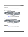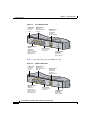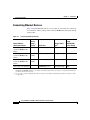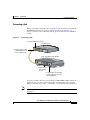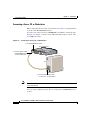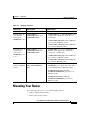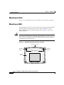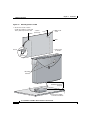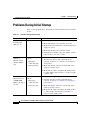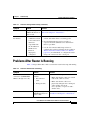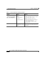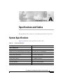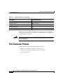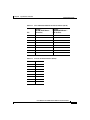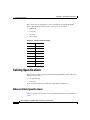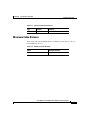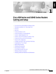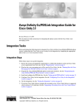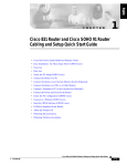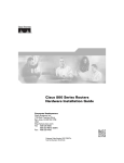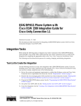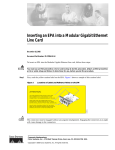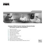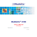
1
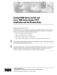
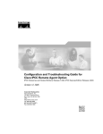
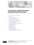
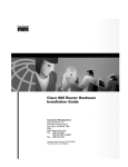
Cisco 806 Router and SOHO 71
Router Hardware Installation Guide
Corporate Headquarters
Cisco Systems, Inc.
170 West Tasman Drive
San Jose, CA 95134-1706
USA
http://www.cisco.com
Tel: 408 526-4000
800 553-NETS (6387)
Fax: 408 526-4100
Customer Order Number: DOC-7810432=
Text Part Number: 78-10432-04
THE SPECIFICATIONS AND INFORMATION REGARDING THE PRODUCTS IN THIS MANUAL ARE SUBJECT TO CHANGE WITHOUT
NOTICE. ALL STATEMENTS, INFORMATION, AND RECOMMENDATIONS IN THIS MANUAL ARE BELIEVED TO BE ACCURATE BUT
ARE PRESENTED WITHOUT WARRANTY OF ANY KIND, EXPRESS OR IMPLIED. USERS MUST TAKE FULL RESPONSIBILITY FOR
THEIR APPLICATION OF ANY PRODUCTS.
THE SOFTWARE LICENSE AND LIMITED WARRANTY FOR THE ACCOMPANYING PRODUCT ARE SET FORTH IN THE INFORMATION
PACKET THAT SHIPPED WITH THE PRODUCT AND ARE INCORPORATED HEREIN BY THIS REFERENCE. IF YOU ARE UNABLE TO
LOCATE THE SOFTWARE LICENSE OR LIMITED WARRANTY, CONTACT YOUR CISCO REPRESENTATIVE FOR A COPY.
The following information is for FCC compliance of Class A devices: This equipment has been tested and found to comply with the limits for a Class
A digital device, pursuant to part 15 of the FCC rules. These limits are designed to provide reasonable protection against harmful interference when
the equipment is operated in a commercial environment. This equipment generates, uses, and can radiate radio-frequency energy and, if not installed
and used in accordance with the instruction manual, may cause harmful interference to radio communications. Operation of this equipment in a
residential area is likely to cause harmful interference, in which case users will be required to correct the interference at their own expense.
The following information is for FCC compliance of Class B devices: The equipment described in this manual generates and may radiate
radio-frequency energy. If it is not installed in accordance with Cisco’s installation instructions, it may cause interference with radio and television
reception. This equipment has been tested and found to comply with the limits for a Class B digital device in accordance with the specifications in
part 15 of the FCC rules. These specifications are designed to provide reasonable protection against such interference in a residential installation.
However, there is no guarantee that interference will not occur in a particular installation.
Modifying the equipment without Cisco’s written authorization may result in the equipment no longer complying with FCC requirements for Class
A or Class B digital devices. In that event, your right to use the equipment may be limited by FCC regulations, and you may be required to correct
any interference to radio or television communications at your own expense.
You can determine whether your equipment is causing interference by turning it off. If the interference stops, it was probably caused by the Cisco
equipment or one of its peripheral devices. If the equipment causes interference to radio or television reception, try to correct the interference by
using one or more of the following measures:
• Turn the television or radio antenna until the interference stops.
• Move the equipment to one side or the other of the television or radio.
• Move the equipment farther away from the television or radio.
• Plug the equipment into an outlet that is on a different circuit from the television or radio. (That is, make certain the equipment and the television
or radio are on circuits controlled by different circuit breakers or fuses.)
Modifications to this product not authorized by Cisco Systems, Inc. could void the FCC approval and negate your authority to operate the product.
The Cisco implementation of TCP header compression is an adaptation of a program developed by the University of California, Berkeley (UCB) as
part of UCB’s public domain version of the UNIX operating system. All rights reserved. Copyright © 1981, Regents of the University of California.
NOTWITHSTANDING ANY OTHER WARRANTY HEREIN, ALL DOCUMENT FILES AND SOFTWARE OF THESE SUPPLIERS ARE
PROVIDED “AS IS” WITH ALL FAULTS. CISCO AND THE ABOVE-NAMED SUPPLIERS DISCLAIM ALL WARRANTIES, EXPRESSED
OR IMPLIED, INCLUDING, WITHOUT LIMITATION, THOSE OF MERCHANTABILITY, FITNESS FOR A PARTICULAR PURPOSE AND
NONINFRINGEMENT OR ARISING FROM A COURSE OF DEALING, USAGE, OR TRADE PRACTICE.
IN NO EVENT SHALL CISCO OR ITS SUPPLIERS BE LIABLE FOR ANY INDIRECT, SPECIAL, CONSEQUENTIAL, OR INCIDENTAL
DAMAGES, INCLUDING, WITHOUT LIMITATION, LOST PROFITS OR LOSS OR DAMAGE TO DATA ARISING OUT OF THE USE OR
INABILITY TO USE THIS MANUAL, EVEN IF CISCO OR ITS SUPPLIERS HAVE BEEN ADVISED OF THE POSSIBILITY OF SUCH
DAMAGES.
CCSP, CCVP, the Cisco Square Bridge logo, Follow Me Browsing, and StackWise are trademarks of Cisco Systems, Inc.; Changing the Way We Work,
Live, Play, and Learn, and iQuick Study are service marks of Cisco Systems, Inc.; and Access Registrar, Aironet, ASIST, BPX, Catalyst, CCDA, CCDP,
CCIE, CCIP, CCNA, CCNP, Cisco, the Cisco Certified Internetwork Expert logo, Cisco IOS, Cisco Press, Cisco Systems, Cisco Systems Capital, the
Cisco Systems logo, Cisco Unity, Empowering the Internet Generation, Enterprise/Solver, EtherChannel, EtherFast, EtherSwitch, Fast Step, FormShare,
GigaDrive, GigaStack, HomeLink, Internet Quotient, IOS, IP/TV, iQ Expertise, the iQ logo, iQ Net Readiness Scorecard, LightStream, Linksys,
MeetingPlace, MGX, the Networkers logo, Networking Academy, Network Registrar, Packet, PIX, Post-Routing, Pre-Routing, ProConnect, RateMUX,
ScriptShare, SlideCast, SMARTnet, StrataView Plus, TeleRouter, The Fastest Way to Increase Your Internet Quotient, and TransPath are registered
trademarks of Cisco Systems, Inc. and/or its affiliates in the United States and certain other countries.
All other trademarks mentioned in this document or Website are the property of their respective owners. The use of the word partner does not imply a
partnership relationship between Cisco and any other company. (0502R)
Cisco 806 Router and SOHO 71 Router Hardware Installation Guide
Copyright © 2005 Cisco Systems, Inc. All rights reserved.
CONTENTS
Preface ix
Audience ix
Organization ix
Conventions x
Related Documentation xi
Obtaining Documentation xii
Cisco.com xii
Documentation DVD xii
Ordering Documentation xiii
Documentation Feedback xiii
Cisco Product Security Overview xiv
Reporting Security Problems in Cisco Products xiv
Obtaining Technical Assistance xv
Cisco Technical Support Website xv
Submitting a Service Request xvi
Definitions of Service Request Severity xvii
Obtaining Additional Publications and Information xvii
CHAPTER
1
Product Overview 1-1
Features 1-1
Router Overview 1-2
Front Panel 1-3
Back Panel 1-3
LEDs 1-5
Cisco 806 Router and SOHO 71 Router Hardware Installation Guide
78-10432-04
v
Contents
CHAPTER
2
Installation 2-1
Preparing for Installation 2-1
Safety 2-1
Warnings 2-2
Preventing Electrostatic Discharge Damage 2-3
Unpacking the Box 2-4
Preventing Router Damage 2-5
Installing Your Router 2-5
Connecting Ethernet Devices 2-6
Connecting a Hub 2-7
Connecting a Server, PC, or Workstation 2-8
Connecting to the Internet 2-9
Connecting a Broadband Modem 2-9
Connecting an Ethernet Switch 2-10
Connecting a Terminal or PC to the Console Port 2-10
Connecting the AC Adapter 2-11
Verifying Router Operation 2-12
Mounting Your Router 2-13
Mounting on Table 2-14
Mounting on Wall 2-14
Connecting to a Website 2-17
What to Do If You Cannot Connect to a Website 2-17
Starting the CRWS Software 2-17
CHAPTER
3
Troubleshooting 3-1
Before You Call Your Cisco Reseller 3-1
Problems During Initial Startup 3-2
Problems After Router Is Running 3-3
Cisco 806 Router and SOHO 71 Router Hardware Installation Guide
vi
78-10432-04
Contents
APPENDIX
A
Specifications and Cables A-1
System Specifications A-1
Port Connector Pinouts A-2
Cabling Specifications A-4
Ethernet Cable Specifications A-4
Maximum Cable Distance A-5
INDEX
Cisco 806 Router and SOHO 71 Router Hardware Installation Guide
78-10432-04
vii
Contents
Cisco 806 Router and SOHO 71 Router Hardware Installation Guide
viii
78-10432-04
Preface
This preface discusses the audience, organization, and conventions used in this
guide. It also discusses related documentation and how to access electronic
documentation.
Audience
This guide is intended for service technicians who have no experience installing
routers and whose goal is to connect the router to the network as quickly as
possible.
Organization
This guide contains the following information:
•
Product Overview—Describes the routers and their features.
•
Installation—Provides information on pre installation procedures, mounting
and connecting the routers, and verifying the router connections.
•
Troubleshooting—Describes problems that might develop and how to
identify and solve them.
•
Specifications and Cables—Provides port connector pinouts and
specifications for cables that you might need to provide.
Cisco 806 Router and SOHO 71 Router Hardware Installation Guide
78-10432-04
ix
Preface
Conventions
Conventions
This section describes the conventions used in this guide.
Note
Means reader take note. Notes contain helpful suggestions or references to
additional information and material.
Caution
This symbol means reader be careful. In this situation, you might do something
that could result in equipment damage or loss of data.
Warning
This warning symbol means danger. You are in a situation that could cause
bodily injury. Before you work on any equipment, be aware of the hazards
involved with electrical circuitry and be familiar with the standard practices
for preventing accidents.
Waarschuwing
Dit waarschuwingssymbool betekent gevaar. U verkeert in een situatie die
lichamelijk letsel kan veroorzaken. Voordat u aan enige apparatuur gaat
werken, dient u zich bewust te zijn van de bij elektrische schakelingen
betrokken risico's en dient u op de hoogte te zijn van standaard maatregelen
om ongelukken te voorkomen.
Varoitus
Attention
Tämä varoitusmerkki merkitsee vaaraa. Olet tilanteessa, joka voi johtaa
ruumiinvammaan. Ennen kuin työskentelet minkään laitteiston parissa, ota
selvää sähkökytkentöihin liittyvistä vaaroista ja tavanomaisista
onnettomuuksien ehkäisykeinoista.
Ce symbole d'avertissement indique un danger. Vous vous trouvez dans une
situation pouvant causer des blessures ou des dommages corporels. Avant de
travailler sur un équipement, soyez conscient des dangers posés par les
circuits électriques et familiarisez-vous avec les procédures couramment
utilisées pour éviter les accidents.
Cisco 806 Router and SOHO 71 Router Hardware Installation Guide
x
78-10432-04
Preface
Related Documentation
Warnung
Dieses Warnsymbol bedeutet Gefahr. Sie befinden sich in einer Situation, die
zu einer Körperverletzung führen könnte. Bevor Sie mit der Arbeit an
irgendeinem Gerät beginnen, seien Sie sich der mit elektrischen
Stromkreisen verbundenen Gefahren und der Standardpraktiken zur
Vermeidung von Unfällen bewußt.
Avvertenza
Questo simbolo di avvertenza indica un pericolo. La situazione potrebbe
causare infortuni alle persone. Prima di lavorare su qualsiasi
apparecchiatura, occorre conoscere i pericoli relativi ai circuiti elettrici ed
essere al corrente delle pratiche standard per la prevenzione di incidenti.
Advarsel
Dette varselsymbolet betyr fare. Du befinner deg i en situasjon som kan føre
til personskade. Før du utfører arbeid på utstyr, må du vare oppmerksom på de
faremomentene som elektriske kretser innebærer, samt gjøre deg kjent med
vanlig praksis når det gjelder å unngå ulykker.
Aviso
Este símbolo de aviso indica perigo. Encontra-se numa situação que lhe
poderá causar danos físicos. Antes de começar a trabalhar com qualquer
equipamento, familiarize-se com os perigos relacionados com circuitos
eléctricos, e com quaisquer práticas comuns que possam prevenir possíveis
acidentes.
¡Atención!
Varning!
Este símbolo de aviso significa peligro. Existe riesgo para su integridad
física. Antes de manipular cualquier equipo, considerar los riesgos que
entraña la corriente eléctrica y familiarizarse con los procedimientos
estándar de prevención de accidentes.
Denna varningssymbol signalerar fara. Du befinner dig i en situation som kan
leda till personskada. Innan du utför arbete på någon utrustning måste du vara
medveten om farorna med elkretsar och känna till vanligt förfarande för att
förebygga skador.
Related Documentation
In addition to this Cisco 806 Router and SOHO 71 Router Hardware Installation
Guide, the Cisco 806 documentation set includes the following:
•
Cisco 806 Router and SOHO 71 Router Cabling and Setup Quick Start Guide
Cisco 806 Router and SOHO 71 Router Hardware Installation Guide
78-10432-04
xi
Preface
Obtaining Documentation
•
Cisco 806 Router Software Configuration Guide
•
Regulatory Compliance and Safety Information for the Cisco 806 Router and
SOHO 71 Router
•
Configuration Note for the Cisco SOHO 71 Router
•
The latest version of the Cisco IOS Release Notes
You might also need to refer to the following documents:
•
Cisco IOS Release 12.0 Quality of Service Solutions Configuration Guide
•
Cisco IOS Security Configuration Guide, Release 12.0
Obtaining Documentation
Cisco documentation and additional literature are available on Cisco.com. Cisco
also provides several ways to obtain technical assistance and other technical
resources. These sections explain how to obtain technical information from Cisco
Systems.
Cisco.com
You can access the most current Cisco documentation at this URL:
http://www.cisco.com/univercd/home/home.htm
You can access the Cisco website at this URL:
http://www.cisco.com
You can access international Cisco websites at this URL:
http://www.cisco.com/public/countries_languages.shtml
Documentation DVD
Cisco documentation and additional literature are available in a Documentation
DVD package, which may have shipped with your product. The Documentation
DVD is updated regularly and may be more current than printed documentation.
The Documentation DVD package is available as a single unit.
Cisco 806 Router and SOHO 71 Router Hardware Installation Guide
xii
78-10432-04
Preface
Documentation Feedback
Registered Cisco.com users (Cisco direct customers) can order a Cisco
Documentation DVD (product number DOC-DOCDVD=) from the Ordering tool
or Cisco Marketplace.
Cisco Ordering tool:
http://www.cisco.com/en/US/partner/ordering/
Cisco Marketplace:
http://www.cisco.com/go/marketplace/
Ordering Documentation
You can find instructions for ordering documentation at this URL:
http://www.cisco.com/univercd/cc/td/doc/es_inpck/pdi.htm
You can order Cisco documentation in these ways:
•
Registered Cisco.com users (Cisco direct customers) can order Cisco product
documentation from the Ordering tool:
http://www.cisco.com/en/US/partner/ordering/
•
Nonregistered Cisco.com users can order documentation through a local
account representative by calling Cisco Systems Corporate Headquarters
(California, USA) at 408 526-7208 or, elsewhere in North America, by
calling 1 800 553-NETS (6387).
Documentation Feedback
You can send comments about technical documentation to [email protected].
You can submit comments by using the response card (if present) behind the front
cover of your document or by writing to the following address:
Cisco Systems
Attn: Customer Document Ordering
170 West Tasman Drive
San Jose, CA 95134-9883
We appreciate your comments.
Cisco 806 Router and SOHO 71 Router Hardware Installation Guide
78-10432-04
xiii
Preface
Cisco Product Security Overview
Cisco Product Security Overview
Cisco provides a free online Security Vulnerability Policy portal at this URL:
http://www.cisco.com/en/US/products/products_security_vulnerability_policy.ht
ml
From this site, you can perform these tasks:
•
Report security vulnerabilities in Cisco products.
•
Obtain assistance with security incidents that involve Cisco products.
•
Register to receive security information from Cisco.
A current list of security advisories and notices for Cisco products is available at
this URL:
http://www.cisco.com/go/psirt
If you prefer to see advisories and notices as they are updated in real time, you
can access a Product Security Incident Response Team Really Simple Syndication
(PSIRT RSS) feed from this URL:
http://www.cisco.com/en/US/products/products_psirt_rss_feed.html
Reporting Security Problems in Cisco Products
Cisco is committed to delivering secure products. We test our products internally
before we release them, and we strive to correct all vulnerabilities quickly. If you
think that you might have identified a vulnerability in a Cisco product, contact
PSIRT:
Tip
•
Emergencies — [email protected]
•
Nonemergencies — [email protected]
We encourage you to use Pretty Good Privacy (PGP) or a compatible product to
encrypt any sensitive information that you send to Cisco. PSIRT can work from
encrypted information that is compatible with PGP versions 2.x through 8.x.
Cisco 806 Router and SOHO 71 Router Hardware Installation Guide
xiv
78-10432-04
Preface
Obtaining Technical Assistance
Never use a revoked or an expired encryption key. The correct public key to use
in your correspondence with PSIRT is the one that has the most recent creation
date in this public key server list:
http://pgp.mit.edu:11371/pks/lookup?search=psirt%40cisco.com&op=index&ex
act=on
In an emergency, you can also reach PSIRT by telephone:
•
1 877 228-7302
•
1 408 525-6532
Obtaining Technical Assistance
For all customers, partners, resellers, and distributors who hold valid Cisco
service contracts, Cisco Technical Support provides 24-hour-a-day,
award-winning technical assistance. The Cisco Technical Support Website on
Cisco.com features extensive online support resources. In addition, Cisco
Technical Assistance Center (TAC) engineers provide telephone support. If you
do not hold a valid Cisco service contract, contact your reseller.
Cisco Technical Support Website
The Cisco Technical Support Website provides online documents and tools for
troubleshooting and resolving technical issues with Cisco products and
technologies. The website is available 24 hours a day, 365 days a year, at this
URL:
http://www.cisco.com/techsupport
Access to all tools on the Cisco Technical Support Website requires a Cisco.com
user ID and password. If you have a valid service contract but do not have a user
ID or password, you can register at this URL:
http://tools.cisco.com/RPF/register/register.do
Cisco 806 Router and SOHO 71 Router Hardware Installation Guide
78-10432-04
xv
Preface
Obtaining Technical Assistance
Note
Use the Cisco Product Identification (CPI) tool to locate your product serial
number before submitting a web or phone request for service. You can access the
CPI tool from the Cisco Technical Support Website by clicking the Tools &
Resources link under Documentation & Tools. Choose Cisco Product
Identification Tool from the Alphabetical Index drop-down list, or click the
Cisco Product Identification Tool link under Alerts & RMAs. The CPI tool
offers three search options: by product ID or model name; by tree view; or for
certain products, by copying and pasting show command output. Search results
show an illustration of your product with the serial number label location
highlighted. Locate the serial number label on your product and record the
information before placing a service call.
Submitting a Service Request
Using the online TAC Service Request Tool is the fastest way to open S3 and S4
service requests. (S3 and S4 service requests are those in which your network is
minimally impaired or for which you require product information.) After you
describe your situation, the TAC Service Request Tool provides recommended
solutions. If your issue is not resolved using the recommended resources, your
service request is assigned to a Cisco TAC engineer. The TAC Service Request
Tool is located at this URL:
http://www.cisco.com/techsupport/servicerequest
For S1 or S2 service requests or if you do not have Internet access, contact the
Cisco TAC by telephone. (S1 or S2 service requests are those in which your
production network is down or severely degraded.) Cisco TAC engineers are
assigned immediately to S1 and S2 service requests to help keep your business
operations running smoothly.
To open a service request by telephone, use one of the following numbers:
Asia-Pacific: +61 2 8446 7411 (Australia: 1 800 805 227)
EMEA: +32 2 704 55 55
USA: 1 800 553-2447
For a complete list of Cisco TAC contacts, go to this URL:
http://www.cisco.com/techsupport/contacts
Cisco 806 Router and SOHO 71 Router Hardware Installation Guide
xvi
78-10432-04
Preface
Obtaining Additional Publications and Information
Definitions of Service Request Severity
To ensure that all service requests are reported in a standard format, Cisco has
established severity definitions.
Severity 1 (S1)—Your network is “down,” or there is a critical impact to your
business operations. You and Cisco will commit all necessary resources around
the clock to resolve the situation.
Severity 2 (S2)—Operation of an existing network is severely degraded, or
significant aspects of your business operation are negatively affected by
inadequate performance of Cisco products. You and Cisco will commit full-time
resources during normal business hours to resolve the situation.
Severity 3 (S3)—Operational performance of your network is impaired, but most
business operations remain functional. You and Cisco will commit resources
during normal business hours to restore service to satisfactory levels.
Severity 4 (S4)—You require information or assistance with Cisco product
capabilities, installation, or configuration. There is little or no effect on your
business operations.
Obtaining Additional Publications and Information
Information about Cisco products, technologies, and network solutions is
available from various online and printed sources.
•
Cisco Marketplace provides a variety of Cisco books, reference guides, and
logo merchandise. Visit Cisco Marketplace, the company store, at this URL:
http://www.cisco.com/go/marketplace/
•
Cisco Press publishes a wide range of general networking, training and
certification titles. Both new and experienced users will benefit from these
publications. For current Cisco Press titles and other information, go to Cisco
Press at this URL:
http://www.ciscopress.com
•
Packet magazine is the Cisco Systems technical user magazine for
maximizing Internet and networking investments. Each quarter, Packet
delivers coverage of the latest industry trends, technology breakthroughs, and
Cisco products and solutions, as well as network deployment and
Cisco 806 Router and SOHO 71 Router Hardware Installation Guide
78-10432-04
xvii
Preface
Obtaining Additional Publications and Information
troubleshooting tips, configuration examples, customer case studies,
certification and training information, and links to scores of in-depth online
resources. You can access Packet magazine at this URL:
http://www.cisco.com/packet
•
iQ Magazine is the quarterly publication from Cisco Systems designed to
help growing companies learn how they can use technology to increase
revenue, streamline their business, and expand services. The publication
identifies the challenges facing these companies and the technologies to help
solve them, using real-world case studies and business strategies to help
readers make sound technology investment decisions. You can access iQ
Magazine at this URL:
http://www.cisco.com/go/iqmagazine
•
Internet Protocol Journal is a quarterly journal published by Cisco Systems
for engineering professionals involved in designing, developing, and
operating public and private internets and intranets. You can access the
Internet Protocol Journal at this URL:
http://www.cisco.com/ipj
•
World-class networking training is available from Cisco. You can view
current offerings at this URL:
http://www.cisco.com/en/US/learning/index.html
Cisco 806 Router and SOHO 71 Router Hardware Installation Guide
xviii
78-10432-04
C H A P T E R
1
Product Overview
The Cisco 806 router and Cisco SOHO 71 router can connect a corporate
telecommuter or small office to an Internet service provider (ISP) over a
broadband or Ethernet connection to the following sites:
•
Corporate LANs
•
The Internet
The router is capable of bridging and multiprotocol routing between LAN and
WAN ports.
Features
Table 1-1 summarizes the features of these routers.
Table 1-1
Cisco 806 Router and SOHO 71 Router Feature Summary
Feature
Routers
Description
10BASE-T Ethernet
ports
Both
Provides connection to 10BASE-T (10-Mbps) Ethernet
networks. Compatible with 10/100-Mbps devices.
Flash memory
Both
8 MB of Flash memory.
Webflash
Both
2 MB of Flash memory reserved for use by the Cisco Router
Web Setup software.
Cisco 806 Router and SOHO 71 Router Hardware Installation Guide
78-10432-04
1-1
Chapter 1
Product Overview
Router Overview
Table 1-1
Cisco 806 Router and SOHO 71 Router Feature Summary (continued)
Feature
Routers
Description
Dynamic RAM
(DRAM)
Cisco 806
32 MB of DRAM built in.
SOHO 71
16 MB of DRAM built in.
Ease of installation
Both
Color-coded ports and cables reduce the chance of
installation error.
Cisco IOS software
Both
Support Cisco IOS software.
Cisco Router Web Setup Both
application
Provide a web-based software tool for basic configurations
and selected applications.
Console port
Both
Provide connection to terminal or PC for software
configuration using command-line interface and for
troubleshooting.
Cable lock
Both
Provide complementary feature for physically securing
router.
Locking power
connector
Both
Lock power connector in place.
Wall-mount feature
Both
Brackets on router bottom provide a means for mounting
router on a wall or vertical surface.
Table 1-2 describes the ports on the Cisco 806 router and the SOHO 71 router.
Table 1-2
Cisco 806 and SOHO 71 Router Ports
Router
LAN Ethernet Ports
WAN Ethernet Port
Console Port
Cisco 806
Four 10BASE-T RJ-45
One 10BASE-T RJ-45
RJ-45
SOHO 71
Four 10BASE-T RJ-45
One 10BASE-T RJ-45
RJ-45
Router Overview
This section shows the front and back panels of the routers.
Cisco 806 Router and SOHO 71 Router Hardware Installation Guide
1-2
78-10432-04
Chapter 1
Product Overview
Router Overview
Front Panel
Figure 1-1 shows the front panel of the Cisco 806 router.
Figure 1-1
Cisco 806 Front Panel
OK
1
RXD TX
D
T
1
2
3
4
RXD
COMPUT
ERS
CISCO 80
0
TXD
51818
INTERNE
SERIES
Figure 1-2 shows the front panel of the SOHO 71 router.
Figure 1-2
SOHO 71 Front Panel
OK
RXD TX
D
INTERNE
T
1
2
3
4
RXD
COMPUT
ERS
CISCO SO
HO
TXD
65861
1
SERIES
Back Panel
Figure 1-3 shows the back panel of the Cisco 806 router.
Cisco 806 Router and SOHO 71 Router Hardware Installation Guide
78-10432-04
1-3
Chapter 1
Product Overview
Router Overview
Figure 1-3
Cisco 806 Back Panel
Cable lock
Physically
secures
router
TO HUB
TO PC
Ethernet ports
Connect to
Ethernet network
devices
ETHERN
ET
10BASET
COMPUT
ERS (E0)
Ethernet port
Connects to
broadband
modem or
Ethernet switch
Model Cis
co 806
CONSOL
E
ETHERN
ET 10BAS
3
2
ET
+5 VDC
1
51814
4
INTERNE
T (E1)
TO HUB/TO PC
button
Determines
the Ethernet
device and cable
type used for
Ethernet port 4
Console port
Connects to PC
or terminal
Locking power
connector
Connects to
power supply
Figure 1-4 shows the back panel of the SOHO 71 router.
SOHO 71 Back Panel
Cable lock
Physically
secures
router
TO HUB
TO PC
Ethernet ports
Connect to
Ethernet network
devices
ETHERN
ET
10BASET
COMPUT
ERS (E0)
Model Cis
Ethernet port
Connects to
broadband
modem or
Ethernet switch
CONSOL
E
co SOHO
71
ETHERN
4
ET 10BAS
3
TO HUB/TO PC
button
Determines
the Ethernet
device and cable
type used for
Ethernet port 4
2
ET
+5 VDC
1
65862
Figure 1-4
INTERNE
T (E1)
Console port
Connects to PC
or terminal
Locking power
connector
Connects to
power supply
Cisco 806 Router and SOHO 71 Router Hardware Installation Guide
1-4
78-10432-04
Chapter 1
Product Overview
Router Overview
LEDs
Table 1-3 summarizes the functions of the LEDs on the routers.
Table 1-3
LED Functions
LED
Color
Function
OK LED
Green
On when power is supplied to the router and when the router
completes the self-test procedure and begins operating.
COMPUTERS 1-4
Green
On when an Ethernet device is connected. Blinks when the
connection has a problem. See the “Troubleshooting” chapter for
more information.
ETHERNET RXD
Green
Blinks when an ETHERNET port receives a packet.
ETHERNET TXD
Green
Blinks when an ETHERNET port sends a packet.
INTERNET 1
Green
On when the INTERNET ETHERNET port is connected to a
broadband modem or to an Ethernet switch.
INTERNET RXD
Green
Blinks when the INTERNET ETHERNET port receives a packet.
INTERNET TXD
Green
Blinks when the INTERNET ETHERNET port sends a packet.
Cisco 806 Router and SOHO 71 Router Hardware Installation Guide
78-10432-04
1-5
Chapter 1
Product Overview
Router Overview
Cisco 806 Router and SOHO 71 Router Hardware Installation Guide
1-6
78-10432-04
C H A P T E R
2
Installation
This chapter provides information on the following topics:
•
Preparing for Installation
•
Preventing Router Damage
•
Installing Your Router
•
Verifying Router Operation
•
Mounting Your Router
•
Connecting to a Website
•
What to Do If You Cannot Connect to a Website
Preparing for Installation
This section provides information on safety, mounting of the router, and
unpacking the router box.
Safety
This section provides the safety warnings and electrostatic and router damage
information applicable to the router.
Cisco 806 Router and SOHO 71 Router Hardware Installation Guide
78-10432-04
2-1
Chapter 2
Installation
Preparing for Installation
Warnings
Before installing the router, read the following warnings:
Warning
Read the installation instructions before you connect the system to its power
source.
Warning
No operator serviceable parts inside. Refer servicing to qualified personnel.
Warning
Before working on a chassis or working near power supplies, unplug the power
cord on AC units; disconnect the power at the circuit breaker on DC units.
Warning
This equipment is intended to be grounded. Ensure that the host is connected to
earth ground during normal use.
Warning
This product relies on the building’s installation for short-circuit (overcurrent)
protection. Ensure that a fuse or circuit breaker no larger than 120 VAC, 15A U.S.
(240 VAC, 10A international) is used on the phase conductors (all
current-carrying conductors).
Warning
Before working on equipment that is connected to power lines, remove jewelry
(including rings, necklaces, and watches). Metal objects will heat up when
connected to power and ground and can cause serious burns or weld the metal
object to the terminals.
Warning
The ports labeled "10BaseT", 100BaseTX", and "10/100" are safety extra-low
voltage (SELV) circuits. SELV circuits should only be connected to other SELV
circuits. Avoid connecting these circuits to telephone network voltage (TNV)
circuits.
Cisco 806 Router and SOHO 71 Router Hardware Installation Guide
2-2
78-10432-04
Chapter 2
Installation
Preparing for Installation
Warning
To avoid electric shock, do not connect safety extra-low voltage (SELV) circuits
to telephone-network voltage (TNV) circuits. LAN ports contain SELV circuits,
and WAN ports contain TNV circuits. Some LAN and WAN ports both use RJ-45
connectors. Use caution when connecting cables.
Warning
Do not work on the system or connect or disconnect cables during periods of
lightning activity.
Preventing Electrostatic Discharge Damage
Electrostatic discharge (ESD) is a transfer of electrostatic charge between bodies
of different electrostatic potentials, such as an operator and a piece of electrical
equipment. It occurs when electronic components are improperly handled, and it
can damage equipment and impair electrical circuitry. Electrostatic discharge is
more likely to occur in the presence of synthetic fibers and dry atmosphere.
Always use the following ESD-prevention procedures when removing and
replacing components:
Step 1
Wear an ESD-preventive wrist strap that you provide, ensuring that it makes good
skin contact.
Caution
To properly guard against ESD damage and shocks, the wrist strap and cord must
operate effectively. Always follow the guidelines in the preceding section,
“Warnings.”
Step 2
Do not touch any exposed contact pins or connector shells of interface ports that
do not have a cable attached.
If cables are connected at one end only, do not touch the exposed pins at the
unconnected end of the cable.
This device is intended for use in residential and commercial environments only.
Cisco 806 Router and SOHO 71 Router Hardware Installation Guide
78-10432-04
2-3
Chapter 2
Installation
Preparing for Installation
Caution
Periodically check the resistance value of the antistatic strap, which should be
between 1 and 10 megohms (Mohms).
Unpacking the Box
Table 2-1 lists the items that come with your router. All these items are in the
accessory kit that is inside the box that your router came in. If any of the items is
missing or damaged, contact your customer service representative.
Table 2-1
Router Box Contents
•
Power cord (black)
•
Desktop power supply
•
Console cable, RJ-45-to-DB-9
•
Two Ethernet cables (yellow)
•
Product documentation
To prepare for installation, follow these steps:
Step 1
Obtain a broadband or Ethernet connection from your service provider.
Step 2
Remove the yellow Ethernet cables, light blue console cable, and product
documentation from the Open Me First bag. Remove the desktop power supply
and the black power cord from the accessory kit. Gather the Ethernet devices to
be connected to the router: hub, servers, workstations, or PCs.
Step 3
If you plan to configure the software using IOS commands via the console port,
provide a terminal or PC to connect to the console port.
Step 4
If you plan to use the cable-lock feature, provide a Kensington or equivalent
locking cable.
Cisco 806 Router and SOHO 71 Router Hardware Installation Guide
2-4
78-10432-04
Chapter 2
Installation
Preventing Router Damage
Preventing Router Damage
Follow these guidelines when connecting devices to your router:
•
Connect the color-coded cables supplied by Cisco Systems to the color-coded
ports on the back panel.
•
If you must supply your own cable, see Appendix A for cabling
specifications. If this appendix does not provide specifications for a particular
cable, we strongly recommend ordering the cable from Cisco Systems.
Installing Your Router
To install the router, you need to perform these tasks in the following order:
•
Connect the Ethernet devices to the router.
•
Connect the router to a broadband modem or Ethernet switch.
•
Connect a terminal or PC to the router (for software configuration using the
command-line interface [CLI] or troubleshooting).
•
Connect the router to the power source.
•
Verify the router installation.
•
Mount the router.
Cisco 806 Router and SOHO 71 Router Hardware Installation Guide
78-10432-04
2-5
Chapter 2
Installation
Installing Your Router
Connecting Ethernet Devices
Table 2-2 lists the Ethernet devices you can connect to the router, the connections
for each device, and the settings of the router TO HUB/TO PC button (the default
setting is IN).
Table 2-2
Connecting Ethernet Devices
Network
Device
Button
Setting1
Hub with equivalent to
router TO HUB/TO PC
button
Hub with equivalent to
router TO HUB/TO PC
button
Router Port
Ethernet Cable
Type2
Router
HUB/NO HUB
Button Setting
MDI (IN)
ETHERNET port 4
Straight-through
IN
MDI-X
(OUT)
ETHERNET port 4
Straight-through
OUT
Hub without equivalent to MDI-X
router TO HUB/TO PC
(OUT)
button
ETHERNET port 4
Straight-through
OUT
Server, PC, or workstation –
ETHERNET port 4
Straight-through
OUT
Network Device
Connected to Router
1. Hub vendors use different names for the button controlling the cable selections. This table uses the Cisco 1528 Micro Hub
10/100 with an MDI/MDI-X button as an example. Determine the button name and setting for your particular hub. Refer to
your hub documentation for details.
2. Cisco provides a yellow straight-through cable. You must provide additional straight-through cables. For details on cables,
see Appendix A.
Cisco 806 Router and SOHO 71 Router Hardware Installation Guide
2-6
78-10432-04
Chapter 2
Installation
Installing Your Router
Connecting a Hub
Before connecting a hub to the router, see Table 2-2 for information on setting the
TO HUB/TO PC button. To connect a hub, follow the steps in Figure 2-1.
(Figure 2-1 shows a Cisco 806 router, but the process is the same for a SOHO 71
router.)
Figure 2-1
Connecting a Hub
1. Set TO HUB/TO PC button.
Cisco 806 router
TO HUB
TO PC
2. Connect yellow cable
to ETHERNET port 4
on Cisco 806 router.
ETHERNET
4
10BASET
COMPUTERS
(E0)
Model Cisc
CONSOLE
o 806
ETHERNET
10BASET
3
2
+5 VDC
1
INTERNET
(E1)
Cisco 1528 Micro Hub 10/100
ET 3X
4X
51815
1X 2X
ETHERN
SPEED
LED
100BaseTX
SOLID
10BaseT
BLINK
1 2 3
4
5 6 7
8
5X
6X
7X
8X
MDI
MDI-X
3. Connect other
end of cable
to hub.
4. If applicable, check setting
of hub equivalent of router
TO HUB/TO PC.
To verify your hub connection, ensure that the COMPUTERS 4 LED on the front
panel is on after you have connected all cables and turned the router on. If the
LED does not turn on, see Table 3-2 in Chapter 3 for troubleshooting information.
Note
Leave PCs attached to the hub turned off until you have completed router
installation.
Cisco 806 Router and SOHO 71 Router Hardware Installation Guide
78-10432-04
2-7
Chapter 2
Installation
Installing Your Router
Connecting a Server, PC, or Workstation
Before connecting the server, PC, or workstation, see Table 2-2 to determine how
to set the router TO HUB/TO PC button.
To connect one of these devices to ETHERNET port number 4, follow the steps
in Figure 2-2. (Figure 2-2 shows a Cisco 806 router, but the process is the same
for a SOHO 71 router.)
Figure 2-2
Connecting a Server, PC, or Workstation
1. Set TO HUB/TO PC button.
Cisco 806 router
TO HUB
TO PC
2. Connect yellow cable
to ETHERNET port 4
on Cisco 806 router.
ETHERNET
4
10BASET
COMPUTERS
(E0)
Model Cisc
CONSOLE
o 806
ETHERNET
10BASET
3
2
+5 VDC
1
INTERNET
(E1)
51817
PC
3. Connect other end of cable
to server, PC, or workstation.
Note
Leave the PCs you connect to the router turned off until you have completed
router installation.
You can connect additional servers, PCs, or workstations to ETHERNET ports 1,
2, and 3.
Cisco 806 Router and SOHO 71 Router Hardware Installation Guide
2-8
78-10432-04
Chapter 2
Installation
Installing Your Router
Connecting to the Internet
You can use an installed broadband modem or Ethernet switch to connect to the
Internet.
Connecting a Broadband Modem
To connect to an installed DSL, cable, or long-reach Ethernet modem, follow the
steps in Figure 2-3. (Figure 2-3 shows a Cisco 806 router, but the process is the
same for a SOHO 71 router.)
Figure 2-3
TO HUB
TO PC
ETHERN
ET
Connecting to a Broadband Modem
10BASET
COMPUT
ERS (E0)
4
Model Cisc
o 806
CONSOL
E
ETHERN
ET 10BASE
T
3
2
+5 VDC
1
INTERNE
T (E1)
Cisco 57
5-LR
E
W
A
N
56958
A
C
T
Y
IT
IV
E
T
E
N
R
E
H
T
R
E
W
O
P
1. Connect yellow cable to
ETHERNET INTERNET port.
2. Connect other end
to modem.
Follow the instructions provided with your broadband modem to determine which
port on the modem to connect to. Turn on the broadband modem if it is not already
turned on.
Cisco 806 Router and SOHO 71 Router Hardware Installation Guide
78-10432-04
2-9
Chapter 2
Installation
Installing Your Router
Connecting an Ethernet Switch
To connect an installed Ethernet switch to the router, follow the steps in
Figure 2-4. (Figure 2-4 shows a Cisco 806 router, but the process is the same for
a SOHO 71 router.)
Figure 2-4
Connecting to an Ethernet Switch
ETHERNET
TO HUB
TO PC
10BASET
COMPUTER
S (E0)
Model Cis
CONSOLE
co 806
ETHERNET
4
3
2
10BASET
+5 VDC
1
INTERNET
(E1)
1
SYSTEM
1X
RPS
MODE
2
3
4
5
6
7
8
9
10
11
60099
1. Connect yellow cable to
ETHERNET INTERNET port.
12
STATUS
1
15X
UTIL
DUPLX
SPEED
1X
2
3
4
5
6
7
2X
8
9
10
11
12
15X
Catalyst 350
16X
2X
1
0 SERIES XL
INLINE POWE
R
16X
2
2. Connect other end of
cable to available port
on Ethernet switch.
Turn on the Ethernet switch if it is not already turned on.
Connecting a Terminal or PC to the Console Port
The CONSOLE port is a service port to which you can connect a terminal or PC
in order to configure the software via the command-line interface (CLI) or to
troubleshoot problems with the router. To connect a terminal or PC to the
CONSOLE port, follow the steps in Figure 2-5. (Figure 2-5 shows a Cisco 806
router, but the process is the same for a SOHO 71 router.)
Cisco 806 Router and SOHO 71 Router Hardware Installation Guide
2-10
78-10432-04
Chapter 2
Installation
Installing Your Router
Figure 2-5
TO HUB
TO PC
Connecting a Terminal or PC
ETHERN
ET
4
10BASET
COMPUT
ERS (E0)
Model Cisco
CONSOL
E
806
ETHERN
ET 10BASE
T
3
2
+5 VDC
1
INTERNE
T (E1)
2. Connect DB-9 connector
to terminal or PC.
51821
1. Connect RJ-45 connector
on light blue cable to
CONSOLE port.
Note
If the factory default configuration does not allow you to connect to the
Internet, it is recommended that you configure your router using the
Cisco Router Web Setup (CRWS) software. The CRWS software is installed
on your router at the factory. See the “What to Do If You Cannot Connect to a
Website” section on page 2-17 for instructions on starting the CRWS software.
Connecting the AC Adapter
To connect the AC adapter, follow the steps in Figure 2-6. (Figure 2-6 shows a
Cisco 806 router, but the process is the same for a SOHO 71 router.)
Warning
The device is designed to work with TN power systems.
Warning
This product relies on the building’s installation for short-circuit (overcurrent)
protection. Ensure that a fuse or circuit breaker no larger than 120 VAC, 15A U.S.
(240 VAC, 16A international) is used on the phase conductors (all
current-carrying conductors).
Cisco 806 Router and SOHO 71 Router Hardware Installation Guide
78-10432-04
2-11
Chapter 2
Installation
Verifying Router Operation
This equipment is designed to be grounded. Ensure that the host is connected
to earth ground during normal use.
Warning
Figure 2-6
Connecting the AC adapter
TO HUB
TO PC
ETHERN
ET
4
10BASET
COMPUT
ERS (E0)
Model Cisc
CONSOL
E
o 806
ETHERN
ET 10BASE
T
3
2
51820
Cisco 806 router
+5 VDC
1
INTERNE
T (E1)
Desktop power
supply
3. Connect power
cord to electrical
outlet.
1. Connect power
supply cable.
2. Connect power cord
to power supply.
Verifying Router Operation
To verify that all PCs are properly connected to the router and that the router is
properly connected to the broadband modem or Ethernet switch, turn on all
connected devices and then use Table 2-3 to help you check the appropriate LEDs.
Cisco 806 Router and SOHO 71 Router Hardware Installation Guide
2-12
78-10432-04
Chapter 2
Installation
Mounting Your Router
Table 2-3
Verifying Operation
Power/Link
LEDs to Check
Normal Patterns
Power
OK
On
To hub, server, PC, COMPUTERS 4,
COMPUTERS RXD, and
or workstation
COMPUTERS TXD
connected to
ETHERNET port 4
•
COMPUTERS 4 is on when the Ethernet port
is physically connected to a hub, PC, or
workstation.
•
COMPUTERS RXD blinks when an Ethernet
port receives an Ethernet packet.
•
COMPUTERS TXD blinks when an Ethernet
port sends an Ethernet packet.
•
COMPUTERS 1, 2, or 3 is on when the
Ethernet port is physically connected to a
server, PC, or workstation.
•
COMPUTERS RXD blinks when an Ethernet
port receives an Ethernet packet.
•
COMPUTERS TXD blinks when an Ethernet
port sends an Ethernet packet.
•
INTERNET 1 is on when the INTERNET
ETHERNET port is physically connected to
a broadband modem or Ethernet switch.
•
INTERNET RXD blinks when the
INTERNET ETHERNET port receives an
Ethernet packet.
•
INTERNET TXD blinks when the
INTERNET ETHERNET port sends an
Ethernet packet.
To servers, PCs, or COMPUTERS 1, 2, or 3,
COMPUTERS RXD, and
workstations
COMPUTERS TXD
connected to
ETHERNET port 1,
2, or 3
To broadband
INTERNET 1, INTERNET
modem or Ethernet RXD, AND INTERNET
switch
TXD
Mounting Your Router
You can mount your router on one of the following surfaces:
•
Table or other horizontal surface
•
Wall or other vertical surface
Cisco 806 Router and SOHO 71 Router Hardware Installation Guide
78-10432-04
2-13
Chapter 2
Installation
Mounting Your Router
Mounting on Table
Do not cover or obstruct the router vents, which are located on the router sides.
Mounting on Wall
You can mount your router on a wall or other vertical surface by using the molded
mounting brackets on the bottom of the router and two number-six, 3/4-in.
(M3.5 x 20 mm) screws. You must provide the screws. Figure 2-7 shows the
mounting brackets.
Caution
If you are mounting your router on drywall, use two hollow wall-anchors
(1/8 in. with 5/16-in. drill bit, or M3 with 8-mm drill bit) to secure the screws. If
the screws are not properly anchored, the strain of the network cable connections
could pull the router from the wall.
Figure 2-7
Wall-Mounting Brackets (Bottom of Router)
Front panel of router
Mounting
bracket
Mounting
bracket
7 58 in. (19.35 cm)
56613
Bottom
of router
Cisco 806 Router and SOHO 71 Router Hardware Installation Guide
2-14
78-10432-04
Chapter 2
Installation
Mounting Your Router
The following conditions must be met when you mount the router:
•
Because you will use the LEDs as status and problem indicators, the front
panel must face upward and be easily visible.
•
The router must be mounted low enough for you to see the LEDs in case you
need to troubleshoot a problem.
•
The power supply must rest on a horizontal surface such as the floor or a
table. If the power supply is not supported, it might place strain on the power
supply cable and cause it to disconnect from the connector on the router back
panel.
To mount the router, follow the steps in Figure 2-8. The last page of this manual
provides a template for measuring the distance between the screws.
Cisco 806 Router and SOHO 71 Router Hardware Installation Guide
78-10432-04
2-15
Chapter 2
Installation
Mounting Your Router
Figure 2-8
Mounting Router on Wall
1. Secure two screws 7-5/8 in.
(19.35 cm) apart into a wall and
1/8 in. (0.32 cm) from the wall.
Wall-mount
screw
7-5/8 in.
(19.35 cm)
Wall
2. Hang router
on screws.
Screw
OK
1/8 in.
(0.32 cm)
1
RX
IN D
TE TX
RN D
ET
CI
O
1
SC
SE
3
RI
ES
EC 4
OM
PU
TE RX
RS D
0
2
80
TX
D
Mounting
brackets
51819
Maximum distance
6 ft (2 m)
3. Place power supply
on horizontal surface.
Cisco 806 Router and SOHO 71 Router Hardware Installation Guide
2-16
78-10432-04
Chapter 2
Installation
Connecting to a Website
Connecting to a Website
The router has been configured to work for the most common type of installation.
Log onto a PC connected to the router, open a web browser, and connect to a
website. If you connected to a website, you have completed setup and can
continue to use the router.
If you cannot display a website, make sure that the broadband modem or Ethernet
switch that the router is connected to is operating, and try again. If you still cannot
connect to a website, you must follow the steps in “What to Do If You Cannot
Connect to a Website.”
What to Do If You Cannot Connect to a Website
If you cannot connect to the Internet using the factory configuration, or if you
have loaded new Cisco IOS software on the router since you installed it, you can
configure the router, using the Cisco Router Web Setup (CRWS) software. The
CRWS software is already loaded on the router, and is run from a PC connected
to the router.
Starting the CRWS Software
Follow these steps to start the CRWS software:
Step 1
Start, or restart, a PC connected to one of the router’s Ethernet ports (1, 2, 3, or
4).
Step 2
Open a web browser. Make sure that the browser is set to work in online mode.
Step 3
•
In Internet Explorer, click the File menu, and verify that the “work offline”
option is unchecked.
•
In Netscape, the default selection in the File menu is set to work online.
Type in the following universal resource locator (URL):
http://10.10.10.1
Cisco 806 Router and SOHO 71 Router Hardware Installation Guide
78-10432-04
2-17
Chapter 2
Installation
What to Do If You Cannot Connect to a Website
Tip
If the CRWS home page does not appear when you enter the URL
http://10.10.10.1, test the connection between the PC and the router by doing
the following:
1.
Check that the OK LED on the router is on, and check the cable connection
between the router and the PC. Be sure that the TO HUB/TO PC button is in
the TO PC position.
2.
If the CRWS home page still does not appear, verify that the web browser’s
“work offline” option is disabled.
3.
If the web page still does not appear, verify that the PC is automatically
configured to receive an IP address. Follow the instructions in the
Cisco Router Web Setup User Guide, which is available on the Cisco 800 and
SOHO Series Product Documentation CD.
Step 4
Click the Router Setup link in the Cisco Router Web Setup home page, and
follow the instructions that appear in the page that is displayed.
Step 5
When you complete setup using CRWS, connect to another website, using the
connected PC. If you successfully connect to the website, then setup is complete,
and you can continue using the router.
Cisco 806 Router and SOHO 71 Router Hardware Installation Guide
2-18
78-10432-04
C H A P T E R
3
Troubleshooting
This chapter describes problems that could occur with the router hardware,
possible causes of the problems, and steps for solving the problems. The problems
are grouped into the following areas:
•
Problems During Initial Startup
•
Problems After Router Is Running
For more information on problems that could occur with the software, refer to the
Cisco 806 Router Software Configuration Guide.
Before You Call Your Cisco Reseller
Some of the solutions in this chapter instruct you to contact your Cisco reseller.
Before you contact your reseller, have the following information ready:
•
Router model and serial number (on the back panel)
•
Maintenance agreement or warranty information
•
Date you received your router
•
Brief description of the problem
•
Brief description of the steps you have taken to solve the problem
Cisco 806 Router and SOHO 71 Router Hardware Installation Guide
78-10432-04
3-1
Chapter 3
Troubleshooting
Problems During Initial Startup
Problems During Initial Startup
Table 3-1 lists problems that a user might encounter when the router is initially
booted.
Table 3-1
Problems During Initial Startup
Symptom
Problem
Solutions
All LEDs,
including OK
LED, are off.
No power to router.
Perform the following tasks in order:
No connection to
modem or
Ethernet switch.
(Internet LED is
off.)
No connection to
Ethernet devices.
(COMPUTER
LEDs 1 through 4
are off.)
A cable-related
problem:
•
Improperly
connected cable.
•
Damaged cable.
A cable-related
problem:
•
Improperly
connected cable.
•
Damaged cable.
1.
Make sure that the power switch is set to ON.
2.
Make sure that all connections to and from the power
supply are secure.
3.
Make sure that the power outlet has power.
4.
If the problem continues, the power supply could be
faulty. Contact your Cisco reseller.
Perform the following tasks in order:
1.
To make sure that you have cabled the device
correctly, see Figure 2-3 or Figure 2-4 in Chapter 2,
“Installation.”
2.
Make sure that the connectors at both ends of the
cable are securely seated.
3.
Make sure the cable is not physically damaged. If it
is, order another cable from Cisco, or replace it with
a similar cable.
Perform the following tasks in order:
1.
To make sure that you have cabled the device
correctly, see Figure 2-1 or Figure 2-2 in Chapter 2,
“Installation.”
2.
Make sure that the connectors at both ends of the
cable are securely seated.
3.
Make sure the cable is not physically damaged. If it
is, order another cable from Cisco Systems, or
replace it with a similar cable
Cisco 806 Router and SOHO 71 Router Hardware Installation Guide
3-2
78-10432-04
Chapter 3
Troubleshooting
Problems After Router Is Running
Table 3-1
Problems During Initial Startup (continued)
Symptom
Problem
Solutions
Improper setting of TO To make sure that the button is set correctly, see
HUB/TO PC button on Table 2-2 in Chapter 2, “Installation.”
router or hub.
Cannot connect to
the Internet
•
•
•
Broadband modem
or Ethernet switch
is not connected or
turned on.
A problem with
the broadband or
WAN service.
•
Reconnect the broadband modem or Ethernet
switch, and ensure that it is receiving power.
•
Check with the Internet service provider or
corporate network administrator to determine if
there is a problem.
•
Use the Cisco Router Web Setup software to
configure the router by following the procedure in
What to Do If You Cannot Connect to a Website,
page 2-17 (recommended), or configure the router
using a PC connected to the console port.
Router is
improperly
configured
Problems After Router Is Running
Table 3-2 lists problems that could occur after the router has been up and running.
Table 3-2
Problems After Router is Running
Symptom
Problem
Solutions
Problems with Ethernet
connection. (COMPUTER
LEDs 1 through 4 are off.)
A cable-related
problem:
Perform the following tasks in order:
•
Disconnected
cable.
•
Damaged cable.
Improper setting of TO
HUB/TO PC button on
router or hub.
1.
Make sure that the connectors at both
ends of the cable are secure.
2.
Make sure that the cable is not
physically damaged. If it is damaged,
order another cable from
Cisco Systems, or replace it with a
similar cable.
To make sure that the button is set correctly,
see Table 2-2 in Chapter 2, “Installation.”
Cisco 806 Router and SOHO 71 Router Hardware Installation Guide
78-10432-04
3-3
Chapter 3
Troubleshooting
Problems After Router Is Running
Table 3-2
Symptom
Problems After Router is Running (continued)
Problem
Connection to the broadband A cable-related
or Ethernet line is intermittent problem:
or lost. (The INTERNET 1
• Disconnected
LED on the front panel is off.)
cable.
•
Damaged cable.
Solutions
Perform the following tasks in order:
1.
Make sure that the connectors at both
ends of the cable are secure.
2.
Make sure that the cable is not
physically damaged. If it is damaged,
order another cable from
Cisco Systems, or replace it with a
similar cable.
Problem with
Contact your broadband line or WAN
broadband line or WAN service provider to determine whether there
service.
is a problem.
Cisco 806 Router and SOHO 71 Router Hardware Installation Guide
3-4
78-10432-04
C H A P T E R
A
Specifications and Cables
This appendix provides system, port, and cabling specifications for the router.
System Specifications
Table 0-1 outlines the system specifications for the router.
Table 0-1
System Specifications
Description
Design Specification
Physical Dimensions
Dimensions (H x W x D)
2.0 x 9.7 x 8.5 in. (5.1 x 24.6 x 21.6 cm)
Weight (does not include desktop power supply)
Cisco 806 router: 1.5 lb (0.68 kg)
Environmental Operating Ranges
Nonoperating temperature
–4 to 149°F (–20 to 65°C)
Nonoperating humidity
5 to 95% relative humidity
Nonoperating altitude
0 to 15,000 ft (4570 m)
Operating temperature
32 to 104°F (0 to 40°C)
Operating humidity
10 to 85% relative humidity
Operating altitude
0 to 10,000 ft (3000 m)
Cisco 806 Router and SOHO 71 Router Hardware Installation Guide
78-10432-04
A-1
Chapter A
Specifications and Cables
Port Connector Pinouts
Table 0-1
System Specifications (continued)
Description
Design Specification
Router Power
AC input voltage
100 to 240 VAC
Frequency
50 to 60 Hz
Power consumption
15W
Voltage
5V
For information on regulatory compliance, refer to the Regulatory Compliance
and Safety Information for Cisco 806 Router and SOHO 71 Router document that
was shipped with your router.
Warning
Ultimate disposal of this product should be handled according to all national
laws and regulations.
Port Connector Pinouts
This section provides pinouts for the following connectors:
•
Ethernet—See Table 0-2, Table 0-5, and Table 0-6.
•
Console (for connecting a terminal or PC)—See Table 0-3.
•
Power—See Table 0-4.
Cisco 806 Router and SOHO 71 Router Hardware Installation Guide
A-2
78-10432-04
Chapter A
Specifications and Cables
Port Connector Pinouts
Table 0-2
Cisco 806 Router Ethernet Connector Pinouts (RJ-45)
Pin
Function
(TO HUB/TO PC Button –
IN Position)
Function
(TO HUB/TO PC Button –
OUT Position)
1
TX+
RX+
2
TX–
RX–
3
RX+
TX+
4
Unused
Unused
5
Unused
Unused
6
RX–
TX–
7
Unused
Unused
8
Unused
Unused
Table 0-3
Console Connector Pinouts (RJ-45)
Pin
Function
1
RTS
2
DTR
3
TXD
4
GND
5
GND
6
RXD
7
DSR
8
CTS
Cisco 806 Router and SOHO 71 Router Hardware Installation Guide
78-10432-04
A-3
Chapter A
Specifications and Cables
Cabling Specifications
The Console port is configured as a data communications equipment (DCE)
device. The default parameters for the console port are as follows:
•
9600 baud
•
8 data bits
•
No parity
•
One stop bit
Table 0-4
Power Connector Pinouts
Pin
Function
1
ROF
2
RTN
3
N.C.
4
N.C.
5
+5
6
RTN
7
N.C.
8
N.C.
Cabling Specifications
This section provides specifications for the following Ethernet cables, which you
might need to provide:
•
Straight-through
•
Crossover
It also provides information on Ethernet cable distance limitations.
Ethernet Cable Specifications
Table 0-5 provides the specifications for straight-through and crossover Ethernet
cables.
Cisco 806 Router and SOHO 71 Router Hardware Installation Guide
A-4
78-10432-04
Chapter A
Specifications and Cables
Cabling Specifications
Table 0-5
Ethernet Cable Specifications
Type
Category
Shielding
10BASE-T
Category 3 or 5
Unshielded twisted-pair (UTP)
Maximum Cable Distance
Table 0-6 provides the maximum distance of Ethernet cables that you can use
between Ethernet devices.
Table 0-6
Maximum Cable Distance
Cable
Maximum Distance
Ethernet cables
328 ft (100 m)
Cisco 806 Router and SOHO 71 Router Hardware Installation Guide
78-10432-04
A-5
Chapter A
Specifications and Cables
Cabling Specifications
Cisco 806 Router and SOHO 71 Router Hardware Installation Guide
A-6
78-10432-04
INDEX
Numerics
connecting
broadband modem 2-9
10BASE-T Ethernet ports 1-1
Ethernet devices 2-6
Ethernet switch 2-10
hubs 2-7
A
PC 2-8, 2-10
accessory kit 2-4
power supply 2-11
AC input voltage A-2
server 2-8
adapter, included 2-4
terminal or PC to console port 2-10
altitude specifications A-1
workstation 2-8
console port 1-2
conventions, hazard x
B
back panel (figure) 1-3
broadband modem, connecting 2-9
D
damage, preventing 2-5
C
cables
documentation
related xi
dynamic RAM 1-2
Ethernet, types of 2-6
included with router 2-4
maximum distances of A-5
specifications (table) A-5
caution statement, defined x
Cisco reseller, contacting 3-1
E
electrostatic damage, preventing 2-3
Ethernet cable
specifications A-5
Cisco 806 Router and SOHO 71 Router Hardware Installation Guide
78-10432-04
IN-1
Index
types of 2-6
M
Ethernet devices, connecting 2-6
Ethernet switch, connecting 2-10
mounting of the router 2-13
F
P
feature summary (table) 1-1
PC, connecting 2-8
Flash memory 1-1
pinouts A-2
frequency specifications A-2
power
problems 3-2
front panel (figure) 1-3
specifications A-2
power connector, locking 1-2
H
power supply, connecting 2-11
hazard statement, defined x
problems
HUB/NO HUB button settings 2-6
after router is running (table) 3-3
hubs, connecting 2-7
during initial startup (table) 3-2
humidity specifications A-1
R
I
router
unpacking 2-4, ?? to 2-4
installation
of the router 2-5
preparing for 2-1, 2-4
S
safety warnings 2-2
L
server, connecting 2-8
LED functions
specifications
in performing troubleshooting 3-2 to 3-4
cable distances (table) A-5
summary of (table) 1-5
Ethernet cable (table) A-5
Cisco 806 Router and SOHO 71 Router Hardware Installation Guide
IN-2
78-10432-04
Index
system A-1
startup problems 3-2
system specifications (table) A-1
T
table mounting 2-14
temperature specifications A-1
U
unpacking the router 2-4, ?? to 2-4
V
voltage specifications A-2
W
wall mounting
description 2-14
figure 2-16
warnings, installation 2-2
weight specifications A-1
workstation, connecting 2-8
Cisco 806 Router and SOHO 71 Router Hardware Installation Guide
78-10432-04
IN-3
Index
Cisco 806 Router and SOHO 71 Router Hardware Installation Guide
IN-4
78-10432-04