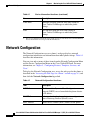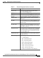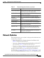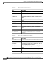
1
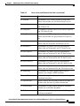
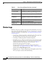
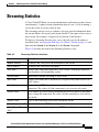
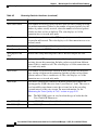
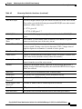
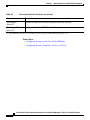
C H A P T E R
8
Monitoring the Cisco Unified IP Phone
Remotely
Each Cisco Unified IP Phone has a web page from which you can view a variety
of information about the phone, including:
•
Device information
•
Network configuration information
•
Network statistics
•
Device logs
•
Streaming statistics
This chapter describes the information that you can obtain from the phone’s web
page. You can use this information to remotely monitor the operation of a phone
and to assist with troubleshooting.
You can also obtain much of this information directly from a phone. For more
information, see Chapter 7, “Viewing Model Information, Status, and Statistics
on the Cisco Unified IP Phone.”
For more information about troubleshooting the Cisco Unified IP Phones
7970G/7971G-GE, see Chapter 9, “Troubleshooting and Maintenance.”
This chapter includes these topics:
•
Accessing the Web Page for a Phone, page 8-2
•
Disabling and Enabling Web Page Access, page 8-3
•
Device Information, page 8-4
•
Network Configuration, page 8-6
Cisco Unified IP Phone Administration Guide for Cisco Unified CallManager 5.1 (SIP), Cisco Unified IP Phones
OL-11524-01
8-1
Chapter 8
Monitoring the Cisco Unified IP Phone Remotely
Accessing the Web Page for a Phone
•
Network Statistics, page 8-11
•
Device Logs, page 8-14
•
Streaming Statistics, page 8-15
Accessing the Web Page for a Phone
To access the web page for a Cisco Unified IP Phone, perform the following these
steps.
Note
If you cannot access the web page, it may be disabled. See the “Disabling and
Enabling Web Page Access” section on page 8-3 for more information.
Procedure
Step 1
Step 2
Obtain the IP address of the Cisco Unified IP Phone using one of these methods:
•
Search for the phone in Cisco Unified CallManager by choosing Device >
Phone. Phones registered with Cisco Unified CallManager display the IP
address at the top of the Phone Configuration web page.
•
On the phone, press the Settings button, choose Network Configuration,
and then scroll to the IP Address option.
Open a web browser and enter the following URL, where IP_address is the IP
address of the Cisco Unified IP Phone:
http://IP_address
The web page for a Cisco Unified IP Phones 7970G/7971G-GE includes these
hyperlinks:
8-2
•
Device Information—Displays device settings and related information for
the phone. For more information, see the “Device Information” section on
page 8-4.
•
Network Configuration—Displays network configuration information and
information about other phone settings. For more information, see the
“Network Configuration” section on page 8-6.
Cisco Unified IP Phone Administration Guide for Cisco Unified CallManager 5.1 (SIP), Cisco Unified IP Phones
OL-11524-01
Chapter 8
Monitoring the Cisco Unified IP Phone Remotely
Disabling and Enabling Web Page Access
•
Network Statistics—Includes the following hyperlinks, which provide
information about network traffic:
– Ethernet Information—Displays information about Ethernet traffic.
For more information, see the “Network Statistics” section on page 8-11.
– Access—Displays information about network traffic to and from the PC
port on the phone. For more information, see the “Network Statistics”
section on page 8-11.
– Network—Displays information about network traffic to and from the
network port on the phone. For more information, see the “Network
Statistics” section on page 8-11.
•
Device Logs—Includes the following hyperlinks, which provide information
that you can use for troubleshooting:
– Console Logs—Includes hyperlinks to individual log files. For more
information, see the “Device Logs” section on page 8-14.
– Core Dumps—Includes hyperlinks to individual dump files.
– Status Messages—Displays up to the 10 most recent status messages
that the phone has generated since it was last powered up. For more
information, see the “Device Logs” section on page 8-14.
– Debug Display—Displays messages that might be useful to the Cisco
TAC if you require assistance with troubleshooting. For more
information, see the “Device Logs” section on page 8-14.
•
Streaming Statistics—Includes the Stream 1, Stream 2, and Stream 3
hyperlinks, which display a variety of streaming statistics. For more
information, see the “Streaming Statistics” section on page 8-15.
Disabling and Enabling Web Page Access
For security purposes, you may choose to prevent access to the web pages for a
phone. If you do so, you will prevent access to the web pages that are described
in this chapter and to the phone’s User Options web pages.
Cisco Unified IP Phone Administration Guide for Cisco Unified CallManager 5.1 (SIP), Cisco Unified IP Phones
OL-11524-01
8-3
Chapter 8
Monitoring the Cisco Unified IP Phone Remotely
Device Information
To disable access to the web pages for a phone, follow these steps from
Cisco Unified CallManager Administration:
Step 1
Choose Device > Phone.
Step 2
Specify the criteria to find the phone and click Find, or click Find to display a list
of all phones.
Step 3
Click the device name to open the Phone Configuration window for the device.
Step 4
From the Web Access drop-down list box, choose Disabled.
Step 5
Click Update.
Note
Some features, such as Cisco Quality Report Tool, do not function
properly without access to the phone web pages. Disabling web access
also affects any serviceability application that relies on web access, such
as CiscoWorks.
To enable web page access when it is disabled, refer to the preceding steps about
disabling access. Follow the same steps but, choose Enabled in Step 4.
Device Information
The Device Information area on a phone’s web page displays device settings and
related information for the phone. Table 8-1 describes these items.
To display the Device Information area, access the web page for the phone as
described in the “Accessing the Web Page for a Phone” section on page 8-2, and
then click the Device Information hyperlink.
Table 8-1
8-4
Device Information Area Items
Item
Description
MAC Address
Media Access Control (MAC) address of the phone
Host Name
Unique, fixed name that is automatically assigned to
the phone based on its MAC address
Cisco Unified IP Phone Administration Guide for Cisco Unified CallManager 5.1 (SIP), Cisco Unified IP Phones
OL-11524-01
Chapter 8
Monitoring the Cisco Unified IP Phone Remotely
Device Information
Table 8-1
Device Information Area Items (continued)
Item
Description
Phone DN
Directory number assigned to the phone
App Load ID
Identifier of the firmware running on the phone
Boot Load ID
Identifier of the factory-installed load running on the
phone
Version
Version of the firmware running on the phone
Expansion Module 1
Phone load ID for the first Cisco Unified IP Phone
7914 Expansion Module, if connected to the phone
Expansion Module 2
Phone load ID for the second Cisco Unified IP Phone
7914 Expansion Module, if connected to the phone
Hardware Revision
Revision value of the phone hardware
Serial Number
Serial number of the phone
Model Number
Model number of the phone
Message Waiting
Indicates if there is a voice message waiting on any
line for this phone
UDI
Displays the following Cisco Unique Device Identifier
(UDI) information about the phone:
Time
•
Device Type—Indicates hardware type. For
example, phone displays for all phone models
•
Device Description—Displays the name of the
phone associated with the indicated model type
•
Product Identifier—Specifies the phone model
•
Version Identifier1—Represents the hardware
version of the phone
•
Serial Number—Displays the phone’s unique
serial number
Time obtained from the Date/Time Group in
Cisco Unified CallManager to which the phone
belongs
Cisco Unified IP Phone Administration Guide for Cisco Unified CallManager 5.1 (SIP), Cisco Unified IP Phones
OL-11524-01
8-5
Chapter 8
Monitoring the Cisco Unified IP Phone Remotely
Network Configuration
Table 8-1
Device Information Area Items (continued)
Item
Description
Time Zone
Timezone obtained from the Date/Time Group in
Cisco Unified CallManager to which the phone
belongs
Date
Date obtained from the Date/Time Group in
Cisco Unified CallManager to which the phone
belongs
1. The Version Identifier field might display blank if using an older model Cisco Unified IP Phone
because the hardware does not provide this information.
Network Configuration
The Network Configuration area on a phone’s web page displays network
configuration information and information about other phone settings. Table 8-2
describes this information.
You can view and set many of these items from the Network Configuration Menu
and the Device Configuration Menu on the Cisco Unified IP Phone. For more
information, see Chapter 5, “Configuring Features, Templates, Services, and
Users.”
To display the Network Configuration area, access the web page for the phone as
described in the “Accessing the Web Page for a Phone” section on page 8-2, and
then click the Network Configuration hyperlink.
Table 8-2
8-6
Network Configuration Area Items
Item
Description
DHCP Server
IP address of the Dynamic Host Configuration
Protocol (DHCP) server from which the phone obtains
its IP address.
BOOTP Server
Indicates whether the phone obtains its configuration
from a Bootstrap Protocol (BootP) server.
MAC Address
Media Access Control (MAC) address of the phone.
Cisco Unified IP Phone Administration Guide for Cisco Unified CallManager 5.1 (SIP), Cisco Unified IP Phones
OL-11524-01
Chapter 8
Monitoring the Cisco Unified IP Phone Remotely
Network Configuration
Table 8-2
Network Configuration Area Items (continued)
Item
Description
Host Name
Host name that the DHCP server assigned to the
phone.
Domain Name
Name of the Domain Name System (DNS) domain in
which the phone resides.
IP Address
Internet Protocol (IP) address of the phone.
Subnet Mask
Subnet mask used by the phone.
TFTP Server 1
Primary Trivial File Transfer Protocol (TFTP) server
used by the phone.
Default Router 1–5
Default router used by the phone (Default Router 1)
and optional backup routers (Default Router 2–5.
DNS Server 1–5
Primary Domain Name System (DNS) server (DNS
Server 1) and optional backup DNS servers (DNS
Server 2–5) used by the phone.
Operational VLAN ID
Auxiliary Virtual Local Area Network (VLAN)
configured on a Cisco Catalyst switch in which the
phone is a member.
Admin. VLAN ID
Auxiliary VLAN in which the phone is a member.
Cisco Unified IP Phone Administration Guide for Cisco Unified CallManager 5.1 (SIP), Cisco Unified IP Phones
OL-11524-01
8-7
Chapter 8
Monitoring the Cisco Unified IP Phone Remotely
Network Configuration
Table 8-2
Network Configuration Area Items (continued)
Item
Description
CallManager 1–5
Host names or IP addresses, in prioritized order, of the
Cisco Unified CallManager servers with which the
phone can register. An item can also show the IP
address of an SRST router that is capable of providing
limited Cisco Unified CallManager functionality, if
such a router is available.
For an available server, an item will show the
Cisco Unified CallManager server IP address and one
of the following states:
•
Active—Cisco Unified CallManager server from
which the phone is currently receiving
call-processing services.
•
Standby—Cisco Unified CallManager server to
which the phone switches if the current server
becomes unavailable.
•
Blank—No current connection to this
Cisco Unified CallManager server.
An option may also include the Survivable Remote
Site Telephony (SRST) designation, which indicates
an SRST router capable of providing
Cisco Unified CallManager functionality with a
limited feature set. This router assumes control of call
processing if all other Cisco Unified CallManager
servers become unreachable. The SRST Cisco Unified
CallManager always appears last in the list of servers,
even if it is active. You configure the SRST router
address in the Device Pool section in Cisco Unified
CallManager.
8-8
Information URL
URL of the help text that appears on the phone.
Directories URL
URL of the server from which the phone obtains
directory information.
Messages URL
URL of the server from which the phone obtains
message services.
Cisco Unified IP Phone Administration Guide for Cisco Unified CallManager 5.1 (SIP), Cisco Unified IP Phones
OL-11524-01
Chapter 8
Monitoring the Cisco Unified IP Phone Remotely
Network Configuration
Table 8-2
Network Configuration Area Items (continued)
Item
Description
Services URL
URL of the server from which the phone obtains
Cisco Unified IP Phone services.
DHCP Enabled
Indicates whether DHCP is being used by the phone.
DHCP Address
Released
Indicates the setting of the DHCP Address Released
option on the phone’s Network Configuration menu.
Alternate TFTP
Indicates whether the phone is using an alternative
TFTP server.
Idle URL
URL that the phone displays when the phone has not
been used for the time specified by Idle URL Time and
no menu is open.
Idle URL Time
Number of seconds that the phone has not been used
and no menu is open before the XML service specified
by Idle URL is activated.
Proxy Server URL
URL of proxy server, which makes HTTP requests to
non-local host addresses on behalf of the phone HTTP
client and provides responses from the non-local host
to the phone HTTP client.
Authentication URL
URL that the phone uses to validate requests made to
the phone web server.
SW Port Configuration Speed and duplex of the switch port, where:
•
A—Auto Negotiate
•
10H—10-BaseT/half duplex
•
10F—10-BaseT/full duplex
•
100H—100-BaseT/half duplex
•
100F—100-BaseT/full duplex
•
1000H—1000-BaseT/half duplex
•
1000F—1000-BaseT/full duplex
•
No Link—No connection to the switch port
Cisco Unified IP Phone Administration Guide for Cisco Unified CallManager 5.1 (SIP), Cisco Unified IP Phones
OL-11524-01
8-9
Chapter 8
Monitoring the Cisco Unified IP Phone Remotely
Network Configuration
Table 8-2
8-10
Network Configuration Area Items (continued)
Item
Description
PC Port Configuration
Speed and duplex of the switch port, where:
•
A—Auto Negotiate
•
10H—10-BaseT/half duplex
•
10F—10-BaseT/full duplex
•
100H—100-BaseT/half duplex
•
100F—100-BaseT/full duplex
•
1000H—1000-BaseT/half duplex
•
1000F—1000-BaseT/full duplex
•
No Link—No connection to the PC port
TFTP Server 2
Backup TFTP server that the phone uses if the primary
TFTP server is unavailable.
User Locale
User locale associated with the phone user. Identifies a
set of detailed information to support users, including
language, font, date and time formatting, and
alphanumeric keyboard text information.
Network Locale
Network locale associated with the phone user.
Identifies a set of detailed information to support the
phone in a specific location, including definitions of
the tones and cadences used by the phone.
Headset enabled
Indicates whether the Headset button is enabled on the
phone.
User Locale Version
Version of the user locale loaded on the phone.
Network Locale
Version
Version of the network locale loaded on the phone.
PC Port Disabled
Indicates whether the PC port on the phone is enabled
or disabled.
Speaker Enabled
Indicates whether the speakerphone is enabled on the
phone.
GARP Enabled
Indicates whether the phone learns MAC addresses
from Gratuitous ARP responses.
Cisco Unified IP Phone Administration Guide for Cisco Unified CallManager 5.1 (SIP), Cisco Unified IP Phones
OL-11524-01
Chapter 8
Monitoring the Cisco Unified IP Phone Remotely
Network Statistics
Table 8-2
Network Configuration Area Items (continued)
Item
Description
Voice VLAN Enabled
Indicates whether the phone allows a device attached
to the PC port to access the Voice VLAN.
Auto Line Select
Indicates whether the phone shifts the call focus to
incoming calls on all lines.
DSCP for Call Control DSCP IP classification for call control signaling.
DSCP for
Configuration
DSCP IP classification for any phone configuration
transfer.
DSCP for Services
DSCP IP classification for phone-based services.
Security Mode
Displays the security mode that is set for the phone.
Web Access Enabled
Indicates whether web access is enabled (Yes) or
disabled (No) for the phone.
Span to PC Port
Indicates whether the phone will forward packets
transmitted and received on the network port to the
access port.
PC VLAN
VLAN used to identify and remove 802.1P/Q tags
from packets sent to the PC
Network Statistics
These network statistics areas on a phone’s web page provide information about
network traffic on the phone:
•
Ethernet Information area—Displays information about Ethernet traffic.
Table 8-3 describes the items in this area.
•
Access area—Displays information about network traffic to and from the PC
port on the phone. Table 8-4 describes the items in this area.
•
Network area—Displays information about network traffic to and from the
network port on the phone. Table 8-4 describes the items in this area.
To display a network statistics area, access the web page for the phone as
described in the “Accessing the Web Page for a Phone” section on page 8-2, and
then click the Ethernet Information, the Access, and or the Network hyperlink.
Cisco Unified IP Phone Administration Guide for Cisco Unified CallManager 5.1 (SIP), Cisco Unified IP Phones
OL-11524-01
8-11
Chapter 8
Monitoring the Cisco Unified IP Phone Remotely
Network Statistics
Table 8-3
Item
Description
Tx Frames
Total number of packets transmitted by the phone
Tx broadcast
Total number of broadcast packets transmitted by the
phone
Tx multicast
Total number of multicast packets transmitted by the
phone
Tx unicast
Total number of unicast packets transmitted by the
phone
Rx Frames
Total number of packets received by the phone
Rx broadcast
Total number of broadcast packets received by the
phone
Rx multicast
Total number of multicast packets received by the
phone
Rx unicast
Total number of unicast packets received by the phone
RxPacketNoDes
Total number of shed packets caused by no DMA
descriptor
Table 8-4
8-12
Ethernet Information Area Items
Access Area and Network Area Items
Item
Description
Rx totalPkt
Total number of packets received by the phone
Rx crcErr
Total number of packets received with CRC failed
Rx alignErr
Total number of packets received between 64 and 1522
bytes in length that have a bad FCS
Rx multicast
Total number of multicast packets received by the
phone
Rx broadcast
Total number of broadcast packets received by the
phone
Rx unicast
Total number of unicast packets received by the phone
Cisco Unified IP Phone Administration Guide for Cisco Unified CallManager 5.1 (SIP), Cisco Unified IP Phones
OL-11524-01
Chapter 8
Monitoring the Cisco Unified IP Phone Remotely
Network Statistics
Table 8-4
Access Area and Network Area Items (continued)
Item
Description
Rx shortErr
Total number of FCS error packets or Align error
packets received that are less than 64 bytes in size
Rx shortGood
Total number of good packets received that are less
than 64 bytes size
Rx longGood
Total number of good packets received that are greater
than 1522 bytes in size
Rx longErr
Total number of FCS error packets or Align error
packets received that are greater than 1522 bytes in
size
Rx size64
Total number of packets received, including bad
packets, that are between 0 and 64 bytes in size
Rx size65to127
Total number of packets received, including bad
packets, that are between 65 and 127 bytes in size
Rx size128to255
Total number of packets received, including bad
packets, that are between 128 and 255 bytes in size
Rx size256to511
Total number of packets received, including bad
packets, that are between 256 and 511 bytes in size
Rx size512to1023
Total number of packets received, including bad
packets, that are between 512 and 1023 bytes in size
Rx size1024to1518
Total number of packets received, including bad
packets, that are between 1024 and 1518 bytes in size
Rx tokenDrop
Total number of packets dropped due to lack of
resources (for example, FIFO overflow)
Tx excessDefer
Total number of packets delayed from transmitting due
to medium being busy
Tx lateCollision
Number of times that collisions occurred later than 512
bit times after the start of packet transmission
Tx totalGoodPkt
Total number of good packets (multicast, broadcast,
and unicast) received by the phone
Tx Collisions
Total number of collisions that occurred while a packet
was being transmitted
Cisco Unified IP Phone Administration Guide for Cisco Unified CallManager 5.1 (SIP), Cisco Unified IP Phones
OL-11524-01
8-13
Chapter 8
Monitoring the Cisco Unified IP Phone Remotely
Device Logs
Table 8-4
Access Area and Network Area Items (continued)
Item
Description
Tx excessLength
Total number of packets not transmitted because the
packet experienced 16 transmission attempts
Tx broadcast
Total number of broadcast packets transmitted by the
phone
Tx multicast
Total number of multicast packets transmitted by the
phone
Neighbor Device ID
Identifier of a device connected to this port
Neighbor IP Address
IP address of the neighbor device
Neighbor Port
Neighbor device port to which the phone is connected
Device Logs
The Device Logs area on a phone’s web page provides information you can use to
help monitor and troubleshoot the phone. To access a device log area, access the
web page for the phone as described in the “Accessing the Web Page for a Phone”
section on page 8-2.
•
Console Logs—Includes hyperlinks to individual log files. The console log
files include debug and error messages received on the phone.
•
Core Dumps—Includes hyperlinks to individual dump files.
•
Status Messages area—Displays up to the 10 most recent status messages that
the phone has generated since it was last powered up. You can also see this
information from the Status Messages screen on the phone. Table 7-2
describes the status messages that can appear.
To display the Status Messages, access the web page for the phone as
described in the “Accessing the Web Page for a Phone” section on page 8-2,
and then click the Status Messages hyperlink.
•
8-14
Debug Display area—Displays debug messages that might be useful to Cisco
TAC if you require assistance with troubleshooting.
Cisco Unified IP Phone Administration Guide for Cisco Unified CallManager 5.1 (SIP), Cisco Unified IP Phones
OL-11524-01
Chapter 8
Monitoring the Cisco Unified IP Phone Remotely
Streaming Statistics
Streaming Statistics
A Cisco Unified IP Phone can stream information to and from up to three devices
simultaneously. A phone streams information when it is on a a call or running a
service that sends or receives audio or data.
The streaming statistics areas on a phone’s web page provide information about
the streams. Most calls use only one stream (Stream 1), but some calls use two or
three stream. For example, a barged call uses Stream 1 and Stream 2.
To display a Streaming Statistics area, access the web page for the phone as
described in the “Accessing the Web Page for a Phone” section on page 8-2, and
then click the Stream 1, the Stream 2, or the Stream 3 hyperlink.
Table 8-5 describes the items in the Streaming Statistics areas.
Table 8-5
Streaming Statistics Area Items
Item
Description
Remote Address
IP address and UDP port of the destination of the stream.
Local Address
IP address and UPD port of the phone.
Start Time
Internal time stamp indicating when Cisco Unified CallManager requested
that the phone start transmitting packets.
Stream Status
Indication of whether streaming is active or not.
Host Name
Unique, fixed name that is automatically assigned to the phone based on its
MAC address.
Sender Packets
Total number of RTP data packets transmitted by the phone since starting this
connection. The value is 0 if the connection is set to receive only mode.
Sender Octets
Total number of payload octets transmitted in RTP data packets by the phone
since starting this connection. The value is 0 if the connection is set to receive
only mode.
Sender Codec
Type of audio encoding used for the transmitted stream.
Sender Reports Sent1
Number of times the RTCP Sender Reports have been sent.
Sender Report Time
Sent1
Internal time stamp indicating when a RTCP Sender Report was sent.
Cisco Unified IP Phone Administration Guide for Cisco Unified CallManager 5.1 (SIP), Cisco Unified IP Phones
OL-11524-01
8-15
Chapter 8
Monitoring the Cisco Unified IP Phone Remotely
Streaming Statistics
Table 8-5
Streaming Statistics Area Items (continued)
Item
Description
Rcvr Lost Packets
Total number of RTP data packets that have been lost since starting receiving
data on this connection. Defined as the number of expected packets less the
number of packets actually received, where the number of received packets
includes any that are late or duplicate. The value displays as 0 if the
connection was set to send-only mode.
Avg Jitter
Estimate of mean deviation of the RTP data packet inter-arrival time,
measured in milliseconds. The value displays as 0 if the connection was set to
send-only mode.
Rcvr Codec
Type of audio encoding used for the received stream.
Rcvr Reports
Sent1
Number of times the RTCP Receiver Reports have been sent.
Rcvr Report Time
Sent1
Internal time stamp indicating when a RTCP Receiver Report was sent.
Rcvr Packets
Total number of RTP data packets received by the phone since starting
receiving data on this connection. Includes packets received from different
sources if this is a multicast call. The value displays as 0 if the connection was
set to send-only mode.
Rcvr Octets
Total number of payload octets received in RTP data packets by the device
since starting reception on the connection. Includes packets received from
different sources if this is a multicast call. The value displays as 0 if the
connection was set to send-only mode.
MOS LQK
Score that is an objective estimate of the mean opinion score (MOS) for
listening quality (LQK) that rates from 5 (excellent) to 1 (bad). This score is
based on audible concealment events due to frame loss in the preceding
8-second interval of the voice stream. For more information, see the
“Monitoring the Voice Quality of Calls” section on page 9-20.
Note
The MOS LQK score can vary based on the type of codec that the
Cisco Unified IP Phone uses.
Avg MOS LQK
Average MOS LQK score observed for the entire voice stream.
Min MOS LQK
Lowest MOS LQK score observed from start of the voice stream.
8-16
Cisco Unified IP Phone Administration Guide for Cisco Unified CallManager 5.1 (SIP), Cisco Unified IP Phones
OL-11524-01
Chapter 8
Monitoring the Cisco Unified IP Phone Remotely
Streaming Statistics
Table 8-5
Streaming Statistics Area Items (continued)
Item
Description
Max MOS LQK
Baseline or highest MOS LQK score observed from start of the voice stream.
These codecs provide the following maximum MOS LQK score under normal
conditions with no frame loss:
•
G.711 gives 4.5
•
G.729 A /AB gives 3.7
MOS LQK Version
Version of the Cisco proprietary algorithm used to calculate MOS LQK
scores.
Cumulative Conceal
Ratio
Total number of concealment frames divided by total number of speech
frames received from start of the voice stream.
Interval Conceal Ratio
Ratio of concealment frames to speech frames in preceding 3-second interval
of active speech. If using voice activity detection (VAD), a longer interval
might be required to accumulate 3 seconds of active speech.
Max Conceal Ratio
Highest interval concealment ratio from start of the voice stream.
Conceal Secs
Number of seconds that have concealment events (lost frames) from the start
of the voice stream (includes severely concealed seconds).
Severely Conceal Secs Number of seconds that have more than 5 percent concealment events (lost
frames) from the start of the voice stream.
Latency1
Estimate of the network latency, expressed in milliseconds. Represents a
running average of the round-trip delay, measured when RTCP receiver report
blocks are received.
Max Jitter
Maximum value of instantaneous jitter, in milliseconds.
Sender Size
RTP packet size, in milliseconds, for the transmitted stream.
Sender Reports
Received1
Number of times RTCP Sender Reports have been received.
Sender Report Time
Received1
Last time at which an RTCP Sender Report was received.
Rcvr Size
RTP packet size, in milliseconds, for the received stream.
Rcvr Discarded
RTP packets received from network but discarded from jitter buffers.
Cisco Unified IP Phone Administration Guide for Cisco Unified CallManager 5.1 (SIP), Cisco Unified IP Phones
OL-11524-01
8-17
Chapter 8
Monitoring the Cisco Unified IP Phone Remotely
Streaming Statistics
Table 8-5
Streaming Statistics Area Items (continued)
Item
Description
Rcvr Reports
Received1
Number of times RTCP Receiver Reports have been received.
Rcvr Report Time
Received1
Last time at which an RTCP Receiver Report was received.
1. When the RTP Control Protocol is disabled, no data generates for this field and thus displays as 0.
Related Topics
8-18
•
Configuring Settings on the Cisco Unified IP Phone
•
Configuring Features, Templates, Services, and Users
Cisco Unified IP Phone Administration Guide for Cisco Unified CallManager 5.1 (SIP), Cisco Unified IP Phones
OL-11524-01
Chapter 8
Monitoring the Cisco Unified IP Phone Remotely
Streaming Statistics
•
Call Statistics Screen, page 7-16
•
Monitoring the Voice Quality of Calls, page 9-20
Cisco Unified IP Phone Administration Guide for Cisco Unified CallManager 5.1 (SIP), Cisco Unified IP Phones
OL-11524-01
8-19
Chapter 8
Monitoring the Cisco Unified IP Phone Remotely
Streaming Statistics
8-20
Cisco Unified IP Phone Administration Guide for Cisco Unified CallManager 5.1 (SIP), Cisco Unified IP Phones
OL-11524-01