1
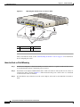
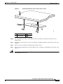
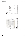
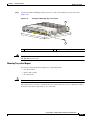
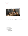
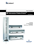
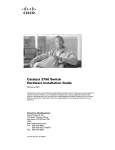
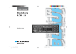
CH A P T E R
2
Switch Installation
This chapter describes how to start your switch and how to interpret the power-on self-test (POST) that
ensures proper operation. It also describes how to install the switch.
Read the topics and perform the procedures in this order:
•
Preparing for Installation, page 2-1
•
Verifying Switch Operation, page 2-5
•
Mounting the Switch, page 2-5
•
Installing a Cover for the Reset Button (Optional), page 2-24
•
Installing the Power Cord Retainer (Optional), page 2-25
•
Installing the Cable Guard (Optional), page 2-28
•
Connecting Devices to the Ethernet Ports, page 2-33
Preparing for Installation
•
Warnings, page 2-1
•
Installation Guidelines, page 2-3
•
Equipment That You Supply, page 2-4
•
Box Contents, page 2-4
•
Powering the Switch, page 2-4
Warnings
These warnings are translated into several languages in the Regulatory Compliance and Safety
Information for the Catalyst 3560-C and the 2960-C Switches guide.
Warning
Before working on equipment that is connected to power lines, remove jewelry (including rings,
necklaces, and watches). Metal objects will heat up when connected to power and ground and can
cause serious burns or weld the metal object to the terminals. Statement 43
Catalyst 3560-C and 2960-C Switch Hardware Installation Guide
OL-23803-02
2-1
Chapter 2
Switch Installation
Preparing for Installation
Warning
Read the wall-mounting instructions carefully before beginning installation. Failure to use the
correct hardware or to follow the correct procedures could result in a hazardous situation to people
and damage to the system. Statement 378
Warning
Do not work on the system or connect or disconnect cables during periods of lightning activity.
Statement 1001
Warning
Read the installation instructions before connecting the system to the power source. Statement 1004
Warning
This product relies on the building’s installation for short-circuit (overcurrent) protection. Ensure that
the protective device is rated not greater than:
20 A Statement 1005
Warning
To prevent bodily injury when mounting or servicing this unit in a rack, you must take special
precautions to ensure that the system remains stable. The following guidelines are provided to
ensure your safety:
•
This unit should be mounted at the bottom of the rack if it is the only unit in the rack.
•
When mounting this unit in a partially filled rack, load the rack from the bottom to the top with the heaviest
component at the bottom of the rack.
•
If the rack is provided with stabilizing devices, install the stabilizers before mounting or servicing the unit in
the rack. Statement 1006
Warning
Class 1 laser product. Statement 1008
Warning
This equipment must be grounded. Never defeat the ground conductor or operate the equipment in the
absence of a suitably installed ground conductor. Contact the appropriate electrical inspection
authority or an electrician if you are uncertain that suitable grounding is available. Statement 1024
Warning
Ultimate disposal of this product should be handled according to all national laws and regulations.
Statement 1040
Catalyst 3560-C and 2960-C Switch Hardware Installation Guide
2-2
OL-23803-02
Chapter 2
Switch Installation
Preparing for Installation
Warning
For connections outside the building where the equipment is installed, the following ports must be
connected through an approved network termination unit with integral circuit protection: 10/100/1000
Ethernet. Statement 1044
Warning
To prevent the system from overheating, do not operate it in an area that exceeds the maximum
recommended ambient temperature of: 113°F (45°C)
Statement 1047
Note
For Catalyst 3560CG-8PC-S, 3560CG-8TC-S, and 2960CG-8TC-L switches, the maximum
recommended ambient temperature is: 104°F (40°C).
Warning
No user-serviceable parts inside. Do not open. Statement 1073
Warning
Installation of the equipment must comply with local and national electrical codes. Statement 1074
Warning
To prevent airflow restriction, allow clearance around the ventilation openings to be at least:
3 in. (7.6 cm) Statement 1076
Warning
Hot surface. Statement 1079
Note
Applies to the Catalyst 3560CG-8PC-S switch.
Installation Guidelines
Before installing the switch, these guidelines must be met:
•
The operating environment must be within the ranges listed in Appendix A, “Technical
Specifications.”
•
Cabling is away from sources of electrical noise, such as radios, power lines, and fluorescent
lighting fixtures. Make sure that the cabling is away from other devices that might damage the
cables.
•
Airflow around the switch and through the vents must be unrestricted. We strongly recommend that
you allow at least 3 in. (7.6 cm) of clearance from the left, right, and top sides of the switch to avoid
any flow blockage. If you are installing the switch in a rack, allow at least 1.75 in.
(4 cm) of empty rack space above each switch.
•
Catalyst 3560CG-8PC-S, 2960C-8PC-L, 2960C-12PC-L, 3560C-8PC-S, and 3560C-12PC-S
switches: Allow at least 1.75 in. (4 cm) clearance from the ends of the external heat sink fins.
Catalyst 3560-C and 2960-C Switch Hardware Installation Guide
OL-23803-02
2-3
Chapter 2
Switch Installation
Powering the Switch
•
Temperature around the unit does not exceed 113°F (45°C).
If the switch is installed in a closed environment or in a multirack assembly, the temperature around
it might be greater than normal room temperature.
•
Humidity around the switch must not exceed 95 percent.
•
Altitude at the installation site must not be greater than 10,000 feet (3,049 meters).
•
Do not place any items on the top of the switch.
•
Do not wall-mount the switch with its front panel facing up. Following safety regulations,
wall-mount the switch with its front panel facing down or to the side to prevent airflow restriction
and to provide easier access to the cables.
•
Clearance to the switch front and rear panels meets these conditions:
– You can easily read the front-panel LEDs.
– Access to ports is sufficient for unrestricted cabling.
– The AC power cord can reach from the AC power outlet to the connector on the switch
rear panel.
•
For 10/100 and 10/100/1000 fixed ports, cable lengths from the switch to connected devices are not
more than 328 feet (100 meters).
•
For cable lengths for small form-factor pluggable (SFP)-module connections, see the “SFP Module
Connectors” section on page B-2 and the module documentation.
Equipment That You Supply
You might need this equipment to install the switch:
•
Number-2 Phillips screwdriver
•
Drill with a #27 drill bit (0.144-inch [3.7 mm])
Box Contents
The switch getting started guide on Cisco.com describes the box contents. If any item is missing or
damaged, contact your Cisco representative or reseller for support.
Powering the Switch
Before installing the switch in a rack, on a desk, a shelf, or a wall, you should power on the switch and
verify that it passes POST.
Power the switch:
Catalyst 2960CPD-8PT-L and 2960CPD-8TT-L
•
Connect a 10/100/1000 uplink port to a PoE or PoE+ switch, such as a Catalyst 3750-X.
Or
•
Plug the auxiliary power adapter cord into the switch AUX power connector and into an AC power
outlet.
Catalyst 3560-C and 2960-C Switch Hardware Installation Guide
2-4
OL-23803-02
Chapter 2
Switch Installation
Verifying Switch Operation
You can use both the uplink port and the auxiliary power adapter. However, the auxiliary power
input takes precedence.
Note
Catalyst 3560CPD-8PT-S
•
Connect a 10/100/1000 uplink port to a PoE+ switch, such as a Catalyst 3750-X.
Or
•
Note
Plug the auxiliary power adapter cord into the switch AUX power connector and into an AC power
outlet.
You can use both the uplink port and the auxiliary power adapter. However, the auxiliary power
input takes precedence.
All models (except the Catalyst 2960CPD-8PT-L, 2960CPD-8TT-L, and 3560CPD-8PT-S)
•
Plug the AC power cord to the switch AC power connector and into an AC power outlet.
Verifying Switch Operation
As the switch powers on, it begins the POST, a series of tests that runs automatically to ensure that the
switch functions properly. LEDs blink during the test, which lasts approximately 1 minute. When the
switch begins POST, the System, Status, Duplex, and Speed LEDs turn green. The System LED blinks
green, and the other LEDs remain green.
When the POST completes successfully, the System LED turns green. The other LEDs turn off and then
reflect the switch operating status. If a switch fails POST, the System LED turns amber.
POST failures are usually fatal. Call Cisco technical support representative if your switch fails POST.
After a successful POST, unplug the power cord from the switch. Mount the switch in a rack on a desk
or shelf, under a desk or shelf, or on a wall, as described in the “Mounting the Switch” section on
page 2-5.
Mounting the Switch
•
On a Desk or Shelf (without Mounting Screws)
•
Desk, Shelf, or Wall (with Mounting Screws)
•
With a Mounting Tray
•
In a Rack
•
On a DIN Rail
Catalyst 3560-C and 2960-C Switch Hardware Installation Guide
OL-23803-02
2-5
Chapter 2
Switch Installation
Mounting the Switch
On a Desk or Shelf (without Mounting Screws)
Step 1
Locate the adhesive strip with the rubber feet in the accessory kit.
Step 2
Remove the four rubber feet from the adhesive strip, and attach them to the recessed areas on the bottom
of the unit. This prevents the switch from sliding on the desk or shelf.
Note
Step 3
Warning
We strongly recommend that you attach the rubber feet. Doing so helps prevent airflow
restriction and overheating.
Place the switch on the desk or shelf.
To prevent airflow restriction, allow clearance around the ventilation openings to be at least:
3 in. (7.6 cm) Statement 1076
After you mount the switch, see the “After Installing the Switch” section on page 2-31 for information
about the switch configuration.
Desk, Shelf, or Wall (with Mounting Screws)
You can use the mounting screws to mount the switch:
•
On a desk or a shelf
•
Under a desk or a shelf
•
On a wall
Desk- or Shelf-Mounting
Step 1
Use the screw template to align the mounting screw holes and also as a guide to make sure that you install
the screws into the desk or shelf with proper clearance.
Step 2
Position the screw template on top of the desk or shelf so that the two side-by-side slots face the front of
the desk or shelf, as shown in Figure 2-1. This ensures that the power cord faces the rear of the desk or
shelf after the switch is installed.
Note
Wait before you attach the screw template to the desk or shelf.
Catalyst 3560-C and 2960-C Switch Hardware Installation Guide
2-6
OL-23803-02
Chapter 2
Switch Installation
Mounting the Switch
Figure 2-1
Installing the Mounting Screws on Top of a Desk or a Shelf
2
3
210096
1
1
Screw template 3
2
Screws
Desk or shelf
Step 3
Peel the adhesive strip off the bottom of the screw template, and attach it to the top of the desk or shelf.
Step 4
Use a 0.144-inch (3.7 mm) or a #27 drill bit to drill a 1/2-inch (12.7 mm) hole in the three screw
template slots.
Step 5
Insert three screws in the slots on the screw template, and tighten them until they touch the top of the
screw template.
Step 6
Remove the screw template from the desk or shelf.
Step 7
Place the switch onto the mounting screws, and slide it forward until it locks in place. See Figure 2-2.
Warning
To prevent airflow restriction, allow clearance around the ventilation openings to be at least:
3 in. (7.6 cm) Statement 1076
Catalyst 3560-C and 2960-C Switch Hardware Installation Guide
OL-23803-02
2-7
Chapter 2
Switch Installation
Mounting the Switch
Figure 2-2
Mounting the Switch on Top of a Desk or Shelf
SYST
STAT
SPD
1
2
PoE
CONSOL
E
3
4
5
PD
POWER
OVER ETH
ERNET
Series
PD
6
7
8
282394
DPLX
MODE
1
2
3
1
2
1
Slides on this way 3
2
Screws
Desk or shelf
After you mount the switch, see the “After Installing the Switch” section on page 2-31 for information
about configuring the switch.
Under the Desk- or Shelf-Mounting
Step 1
Use the screw template to align the mounting screw holes and also as a guide to make sure the screws
are installed under the desk or shelf with proper clearance.
Step 2
Position the screw template underneath the desk or shelf so that the two side-by-side slots face the front
of the desk or shelf, as shown in Figure 2-3. This ensures that the power cord faces the rear of the desk
or shelf after the switch is mounted.
Step 3
Peel the adhesive strip off the bottom of the screw template, and attach it to the underside of the desk or
shelf.
Catalyst 3560-C and 2960-C Switch Hardware Installation Guide
2-8
OL-23803-02
Chapter 2
Switch Installation
Mounting the Switch
Figure 2-3
Installing the Mounting Screws Under a Desk or Shelf
1
2
3
1
Desk or shelf
3
Screws
2
Screw template
4
Adhesive
250146
4
3
Step 4
Use a 0.144-inch (3.7 mm) or a #27 drill bit to drill a 1/2-inch (12.7 mm) hole in the three screw
template slots.
Step 5
Insert three screws in the slots on the screw template, and tighten until they touch the top of the screw
template.
Step 6
Remove the screw template from underneath the desk or shelf.
Step 7
Place the switch upside down onto the mounting screws, and slide it forward until it locks in place. See
Figure 2-4.
Warning
To prevent airflow restriction, allow clearance around the ventilation openings to be at least:
3 in. (7.6 cm) Statement 1076
Catalyst 3560-C and 2960-C Switch Hardware Installation Guide
OL-23803-02
2-9
Chapter 2
Switch Installation
Mounting the Switch
Figure 2-4
Mounting the Switch Under a Desk or Shelf
1
282395
2
2
1
ERNET
POWER
CONSOL
OVER ETH
E
PD
4
PoE
MODE
SPD
DPLX
1
2
3
5
6
8
7
Catalyst
2960-C
Series
PD
STAT
SYST
3
1
Desk or shelf
2
Screws
3
Slides on this way
After you mount the switch, see the “After Installing the Switch” section on page 2-31 for information
about configuring the switch.
Wall-Mounting
Warning
Read the wall-mounting instructions carefully before beginning installation. Failure to use the
correct hardware or to follow the correct procedures could result in a hazardous situation to people
and damage to the system. Statement 378
Caution
Do not wall-mount the switch with its front panel facing up. Following safety regulations, wall-mount
the switch with its front panel facing down or to the side to prevent airflow restriction and to provide
easier access to the cables.
Catalyst 3560-C and 2960-C Switch Hardware Installation Guide
2-10
OL-23803-02
Chapter 2
Switch Installation
Mounting the Switch
Step 1
Locate the screw template. The template is used to align the mounting screw holes.
Note
Step 2
Figure 2-5 shows the measurements for the location of the screws on the switch.
Position the screw template so that the two side-by-side slots face toward the floor, as shown in
Figure 2-6.
For the best support of the switch and cables, make sure that you attach the switch securely to a wall stud
or to a firmly attached plywood mounting backboard.
Step 3
Peel the adhesive strip off the bottom of the screw template.
Step 4
Attach the screw template to the wall.
Step 5
Use a 0.144-inch (3.7 mm) or a #27 drill bit to drill a 1/2-inch (12.7 mm) hole in the three screw
template slots.
Step 6
Insert three screws in the slots on the screw template, and tighten until they touch the top of the
screw template.
Step 7
Remove the screw template from the wall.
Figure 2-5
Location of the Mounting Holes on the Switch
6
5
1
2
330380
4
3
1
1.77 in. (4.49 cm)
4
2.67 in. (6.78)
2
3.72 in. (9.44 cm)
5
2.46. in. (6.24)
3
3.62 in. (9.19 cm)
6
Switch
Catalyst 3560-C and 2960-C Switch Hardware Installation Guide
OL-23803-02
2-11
Chapter 2
Switch Installation
Mounting the Switch
Figure 2-6
Installing the Mounting Screws on the Wall
1
2
THIS SID
E
MOUNT AWAY FROM
ING SU
RFACE
SIDE EN
TRY
157828
CABLE
2
3
2
Figure 2-7
Installing the Switch on a Wall
1
2
2
Step 8
2
208926
R
E
S
E
T
U
A
X
V
53
,1
A
.5
3
Place the switch onto the mounting screws, and slide it down until it locks in place. See Figure 2-7.
Catalyst 3560-C and 2960-C Switch Hardware Installation Guide
2-12
OL-23803-02
Chapter 2
Switch Installation
Mounting the Switch
With a Mounting Tray
The mounting kit (part number CMP-MGNT-TRAY=) is optional. You can order it when you order your
switch, or you can order it later from your Cisco representative.
The mounting kit ships contents:
•
Two number-10 Phillips pan-head screws
•
Three number-8 Phillips pan-head screws
•
Mounting tray
•
Magnet
You can use the mounting tray by itself with mounting screws, or with a magnet.
Mounting Tray with Screws
You can use the mounting tray to secure the switch:
Caution
•
On a desk or shelf
•
Under a desk or shelf
•
On a wall
Do not wall-mount the switch with its front panel facing up. Following safety regulations, wall-mount
the switch with its front panel facing down or to the side, to allow sufficient airflow and to provide easier
access to the cables.
This example shows you how to mount the switch on a desk or shelf. You can use a similar procedure to
mount the switch under a desk or on a wall.
Step 1
Place the mounting tray on the desk.
Step 2
Use a 0.144-in. (3.7 mm) or a #27 drill bit to drill three 1/2-in. (12.7 mm) holes in the desk. See
Figure 2-8.
Step 3
Insert the three number-8 Phillips pan-head screws in the slots on the mounting tray, and tighten them.
Figure 2-8
Attaching the Tray to the Desk or Shelf
1
1
2
208923
1
3
Catalyst 3560-C and 2960-C Switch Hardware Installation Guide
OL-23803-02
2-13
Chapter 2
Switch Installation
Mounting the Switch
Number-8 Phillips pan-head screws
2
Mounting tray
3
Desk or shelf
Place the switch onto the mounting screws, and slide the switch until it locks into place. See Figure 2-9.
Figure 2-9
Installing the Switch on the Mounting Tray
282396
Step 4
1
SYST
STAT
DPLX
SPD
MODE
1
2
3
PoE
PD
CONSOL
E
POWER
OVER
ETHERN
ET
4
5
6
Series
PD
7
8
1
2
1
2
3
4
1
Switch
3
Mounting tray
2
Sliding direction
4
Desk
Catalyst 3560-C and 2960-C Switch Hardware Installation Guide
2-14
OL-23803-02
Chapter 2
Switch Installation
Mounting the Switch
Step 5
Use the two number-10 Phillips pan-head screws to secure the mounting tray to the switch. See
Figure 2-10.
Figure 2-10
Securing the Mounting Tray to the Switch
282397
1
SYST
STAT
DPLX
1
SPD
MODE
2
PoE
CONSOL
E
3
4
PD
POWER
5
Series
6
7
PD
8
OVER ETH
ERNET
1
2
2
1
Warning
2
Switch
Number-10 Phillips pan-head screws
To prevent airflow restriction, allow clearance around the ventilation openings to be at least:
3 in. (7.6 cm) Statement 1076
Mounting Tray with a Magnet
You can use a magnet with the mounting tray to mount the switch:
Caution
•
On a metal surface
•
Under a metal surface
•
On a metal wall
Do not use the magnet without a mounting tray.
This example shows you how to mount the switch on a metal wall. You can use a similar procedure to
mount the switch under a metal desk or on a metal desk.
Catalyst 3560-C and 2960-C Switch Hardware Installation Guide
OL-23803-02
2-15
Chapter 2
Switch Installation
Mounting the Switch
Place the switch on the mounting tray. See Figure 2-11.
Figure 2-11
Placing the Switch on the Mounting Tray
282398
Step 1
SYST
STAT
DPLX
1
SPD
MODE
2
3
PoE
4
5
PD
CONSOL
E
POWER
OVER
ETHERN
6
Series
PD
7
8
ET
1
2
1
2
1
Step 2
2
Switch
Mounting tray
Use the two number-10 Phillips pan-head screws to secure the mounting tray to the switch. See
Figure 2-12.
Figure 2-12
Securing the Mounting Tray to the Switch
282397
1
SYST
STAT
DPLX
SPD
MODE
1
2
PoE
CONSOL
E
PD
POWER
3
4
5
Series
6
7
PD
8
OVER ETH
ERNET
1
2
2
1
Step 3
Switch
2
Number-10 Phillips pan-head screws
Place one side of the magnet against the bottom of the mounting tray, as shown in Figure 2-13. Mount
the magnet and switch on a metal wall.
Catalyst 3560-C and 2960-C Switch Hardware Installation Guide
2-16
OL-23803-02
Chapter 2
Switch Installation
Mounting the Switch
Warning
Read the wall-mounting instructions carefully before beginning installation. Failure to use the
correct hardware or to follow the correct procedures could result in a hazardous situation to people
and damage to the system. Statement 378
Caution
Do not wall-mount the switch with its front panel facing up. Following safety regulations, wall-mount
the switch with its front panel facing down or to the side, to allow sufficient airflow and to provide easier
access to the cables.
Figure 2-13
Wall-Mounting with a Magnet
3
2
209025
R
T
E
S
E
X
U
A
53
V
,1
.5
A
1
Warning
1
Switch with the mounting tray attached
2
Magnet
3
Metal wall
To prevent airflow restriction, allow clearance around the ventilation openings to be at least:
3 in. (7.6 cm) Statement 1076
After you mount the switch, see the “After Installing the Switch” section on page 2-31 for information
about configuring the switch.
Catalyst 3560-C and 2960-C Switch Hardware Installation Guide
OL-23803-02
2-17
Chapter 2
Switch Installation
Mounting the Switch
In a Rack
Installing the switch in a rack requires an optional bracket kit that is not included with the switch. You
can order these kits from your Cisco representative:
Warning
•
19-inch rack-mounting brackets (RCKMNT-19-CMPCT=)
•
23- and 24-inch rack-mounting brackets (RCKMNT-23-CMPCT=)
To prevent bodily injury when mounting or servicing this unit in a rack, you must take special
precautions to ensure that the system remains stable. The following guidelines are provided to
ensure your safety:
•
This unit should be mounted at the bottom of the rack if it is the only unit in the rack.
•
When mounting this unit in a partially filled rack, load the rack from the bottom to the top with the heaviest
component at the bottom of the rack.
•
If the rack is provided with stabilizing devices, install the stabilizers before mounting or servicing the unit in
the rack. Statement 1006
To install the switch in a rack, follow the instructions described in these sections:
•
Attaching Brackets to the Switch, page 2-18
•
Mounting the Switch in a Rack, page 2-19
Attaching Brackets to the Switch
Figure 2-14 shows how to attach a 19-inch bracket to one side of the switch. Follow the same steps to
attach the second bracket to the opposite side.
Attaching the 19-inch Brackets for Rack-Mounting
282399
Figure 2-14
SYST
STAT
DPLX
SPD
MODE
1
2
3
PoE
CONSOLE
PD
POWER
OVER
ETHERNE
4
5
Series
6
7
PD
8
T
1
2
1
1
Phillips flat-head screw
Catalyst 3560-C and 2960-C Switch Hardware Installation Guide
2-18
OL-23803-02
Chapter 2
Switch Installation
Mounting the Switch
Figure 2-15 shows how to attach a 23-inch bracket to one side of the switch. Follow the same steps to
attach the second bracket to the opposite side.
Attaching the 23-inch Brackets for Rack-Mounting
282400
Figure 2-15
SYST
STAT
DPLX
SPD
MODE
1
2
3
PoE
CONSOLE
4
POWER
OVER
ETHERNE
Series
5
PD
6
7
PD
8
T
1
2
1
1
Phillips flat-head screw
Mounting the Switch in a Rack
After the brackets are attached to the switch, insert the switch into the rack, and align the bracket in the
rack. Use either the number-12 or number-10 Phillips machine screws to secure the switch in the rack.
See Figure 2-16.
Warning
To prevent airflow restriction, allow clearance around the ventilation openings to be at least:
3 in. (7.6 cm) Statement 1076
Figure 2-16
Mounting the Switch in a Rack
SYST
STAT
DPLX
1
2
3
PoE
CONSOLE
PD
POWER
OVER ETHE
4
5
Series
6
7
PD
8
RNET
1
2
282402
SPD
MODE
1
1
Phillips machine screws
After you mount the switch, see the “After Installing the Switch” section on page 2-31 for information
about the switch configuration.
Catalyst 3560-C and 2960-C Switch Hardware Installation Guide
OL-23803-02
2-19
Chapter 2
Switch Installation
Mounting the Switch
On a DIN Rail
The DIN-mount kit (part number CMP-DIN-MNT=) is optional. You can order it when you order your
switch, or you can order it later from your Cisco representative.
The DIN-mount kit contains:
•
Two number-10 Phillips pan-head screws
•
DIN rail mount
To install the switch on a DIN rail, follow the instructions described in these sections:
•
Attaching the DIN-Mount Tray to the Switch, page 2-20
•
Mounting the Switch on a DIN Rail, page 2-21
•
Removing the Switch from a DIN Rail, page 2-23
Attaching the DIN-Mount Tray to the Switch
Step 1
Place the switch on the DIN rail mount. See Figure 2-17.
Figure 2-17
Placing the Switch on the DIN-Mount Tray
SYST
STAT
DPLX
SPD
MODE
1
2
3
PoE
CONSOL
E
PD
POWER
OVER
ETHERN
ET
4
5
6
Series
PD
7
8
1
2
1
344212
2
1
Switch
2
DIN rail mount
Catalyst 3560-C and 2960-C Switch Hardware Installation Guide
2-20
OL-23803-02
Chapter 2
Switch Installation
Mounting the Switch
Step 2
Use the two number-10 Phillips pan-head screws to secure the DIN rail mount to the switch.
See Figure 2-18.
Figure 2-18
Securing the DIN-Mount Tray to the Switch
1
SYST
STAT
SPD
1
2
3
PoE
CONSOL
4
PD
E
POWER
OVER
ETHERN
ET
5
6
Series
PD
7
8
1
344213
DPLX
MODE
2
2
1
Switch
2
Number-10 Phillips pan-head screws
Mounting the Switch on a DIN Rail
Caution
Warning
Step 1
Do not install the switch with its front panel facing up. Following safety regulations, install the switch
with its front panel facing down, to allow sufficient airflow and to provide easier access to the cables.
To prevent airflow restriction, allow clearance around the ventilation openings to be at least:
3 in. (7.6 cm) Statement 1076
Position the switch directly in front of the DIN rail, making sure that the top of the DIN rail mount clip
hooks over the top of the DIN rail. See Figure 2-19.
Catalyst 3560-C and 2960-C Switch Hardware Installation Guide
OL-23803-02
2-21
Chapter 2
Switch Installation
Mounting the Switch
Figure 2-19
Mounting the Switch on a DIN Rail
344214
T
E
S
E
R
X
U
A
53
V
,1
.5
A
1
1
Switch
Step 2
Rotate the switch down toward the DIN rail until the release tabs on the DIN rail mount clicks.
Step 3
Lift lightly on the bottom of the switch to ensure that it is firmly locked in place.
After you install the switch, see the “After Installing the Switch” section on page 2-31 for information
about the switch configuration.
Catalyst 3560-C and 2960-C Switch Hardware Installation Guide
2-22
OL-23803-02
Chapter 2
Switch Installation
Mounting the Switch
Removing the Switch from a DIN Rail
Step 1
Ensure that power is removed from the switch, and disconnect all cables and connectors from the front
panel of the switch.
Step 2
Pull down on the DIN rail mount release tabs. As the clips release, lift the bottom of the switch.
See Figure 2-20.
Figure 2-20
Switch Removal
344246
T
E
S
E
R
X
U
A
53
V
,1
.5
A
1
1
Switch
Catalyst 3560-C and 2960-C Switch Hardware Installation Guide
OL-23803-02
2-23
Chapter 2
Switch Installation
Installing a Cover for the Reset Button (Optional)
Installing a Cover for the Reset Button (Optional)
You can cover the reset button to prevent accidental or unauthorized reset of your switch.
To install a cover on the reset button:
1.
Locate the cover (in the accessory kit).
2.
Remove the adhesive sticker from the back of the cover.
3.
Apply the cover on the switch. See Figure 2-21 and Figure 2-22 as examples. You can apply the
cover to other switch models as well.
Figure 2-21
Reset Cover on the Catalyst 2960CPD-8PT-L Switch
1
AUX 53
V
330756
RESET
, 1.5A
2
1
2
Switch
Figure 2-22
Reset button cover
Reset Cover on the Catalyst 2960CG-8PC-S Switch
1
330755
RES
RE
SE
ET
T
2
1
Switch
2
Reset button cover
Catalyst 3560-C and 2960-C Switch Hardware Installation Guide
2-24
OL-23803-02
Chapter 2
Switch Installation
Installing the Power Cord Retainer (Optional)
Installing the Power Cord Retainer (Optional)
Note
This section applies to switches with an AC power connector.
The power cord retainer part number (PWR-CLP=) is optional. You can order it when you order your
switch, or you can order it later from your Cisco representative.
Step 1
Choose the sleeve size of the power cord retainer based on the thickness of the cord. The smaller sleeve
can be snapped off and used for thin cords. See Figure 2-26.
Step 2
Slide the retainer around the AC power cord, and pass it around the loop on the switch. See Figure 2-23.
Figure 2-23
RESET
208984
1
Inserting the Retainer through the Lanced Loop
4
2
3
1
AC power cord
3
Sleeve for thinner power cords
2
Power cord retainer
4
Loop
Catalyst 3560-C and 2960-C Switch Hardware Installation Guide
OL-23803-02
2-25
Chapter 2
Switch Installation
Installing the Power Cord Retainer (Optional)
Step 3
Slide the retainer through the first latch. See Figure 2-24.
Figure 2-24
Sliding the Retainer Through the Latch
RESET
208985
1
3
2
Step 4
1
AC power cord
3
2
Smaller sleeve for thin power cords
Latch
Slide the retainer through the other latches to lock it. See Figure 2-25.
Figure 2-25
RESET
208986
1
Locking the Retainer
2
3
(
Step 5
1
AC power cord
2
Sleeve for thin power cords
3
Latches
(Optional) Use the small sleeve for thin power cords. Use the small sleeve to provide greater stability for
thin cords. Detach the sleeve, and slide it over the power cord. See Figure 2-26.
Catalyst 3560-C and 2960-C Switch Hardware Installation Guide
2-26
OL-23803-02
Chapter 2
Switch Installation
Installing the Power Cord Retainer (Optional)
Figure 2-26
Sleeve Around the Power Cord
2
1
208987
1
1
Step 6
2
Sleeve for thin power cords
AC power cord
Secure the AC power cord by pressing on the retainer. See Figure 2-27.
Securing the Power Cord in the Retainer
208988
Figure 2-27
Catalyst 3560-C and 2960-C Switch Hardware Installation Guide
OL-23803-02
2-27
Chapter 2
Switch Installation
Installing the Cable Guard (Optional)
Installing the Cable Guard (Optional)
The cable guard prevents tampering with the cables after the cables are installed. The cable guard
(CMP-CBLE-GRD=) is not included with the switch, but you can order it from your Cisco
representative.
Note
You can use the cable guard when the switch is mounted on a desk, under a desk, or on a wall.
The cable guard is shipped with these items:
Step 1
•
Two 0.5 in. (12.7 mm) number-8 Phillips wood screws
•
Two number-10 Phillips pan-head screws
•
Two washers
(Optional) Attach the supplied washers before you install the cable guard. See Figure 2-28.
Note
This is only required if you are not installing the wall-mount brackets.
Figure 2-28
Using the Washer
SYST
STAT
SPD
1
2
PoE
CONSOL
E
PD
POWER
OVER
3
4
5
Series PD
6
7
8
330047
DPLX
MODE
ETHERN
ET
1
2
1
1
Washer
Catalyst 3560-C and 2960-C Switch Hardware Installation Guide
2-28
OL-23803-02
Chapter 2
Switch Installation
Installing the Cable Guard (Optional)
Step 2
Use the supplied number-10 pan-head screws to attach the cable guard to the switch. See Figure 2-29.
Figure 2-29
Attaching the Cable Guard to the Switch
1
2
SYST
STAT
SPD
1
2
PoE
CONSOL
E
3
Catalyst
29
4
5
PD
POWER
OVE
6
7
60-C Se
ries PD
8
208916
DPL X
MODE
R ETH
ERNET
1
2
3
Step 3
1
Switch
3
2
Cable guard
Two number-10 Phillips pan-head screws
Loosen the number-10 Phillips pan-head screws, slide the cable guide out, and pivot it upwards so that
you can install the cables. See Figure 2-30.
Figure 2-30
Pivoting the Cable Guard Upwards
2
SYST
STAT
PD
2
3
4
Catalyst
5
6
7
2960-C
Series PD
8
1
208917
1
CONSOLE
2
1
1
2
Cable guard
Pivot direction for cable guard pivots
Attach the cables to the switch. See Figure 2-31.
Catalyst 3560-C and 2960-C Switch Hardware Installation Guide
OL-23803-02
2-29
Chapter 2
Switch Installation
Installing the Cable Guard (Optional)
Figure 2-31
Attaching the Cables to the Switch
2
SYST
STAT
SPD
1
2
PoE
PD
CONSOL
E
POWER
OVER
3
4
Catalyst
5
6
7
ETHERN
ET
2960-C
Series PD
8
1
208918
DPLX
MODE
2
1
1
Step 4
2
Cable guard
Pivot direction for cable guard pivots
Guide the connected cables through the slots in the front of the cable guard. Slide the cable guide in as
shown in Figure 2-33. Tighten the screws.
Guiding the Cables through the Guard
330040
Figure 2-32
Catalyst 3560-C and 2960-C Switch Hardware Installation Guide
2-30
OL-23803-02
Chapter 2
Switch Installation
After Installing the Switch
Step 5
(Optional) To attach the cable guard to the desk or wall, use a 0.144-inch (3.7 mm) or a #27 drill bit to
drill 1/2-inch (12.7 mm) holes at each of the two mounting locations. Insert the supplied 0.5 in.
(12.7 mm) number-8 Phillips wood screws and tighten them as shown in Figure 2-33.
Figure 2-33
Securing the Cable Guard to the Desk
1
208919
1
2
1
Number-8 Phillips wood screws
2
Desk or shelf
After Installing the Switch
1.
Power on the switch. See the “Verifying Switch Operation” section on page 2-5.
2.
Connect to a 10/100 or 10/100/1000 port, and run Express Setup. See the switch getting started guide
for instructions.
3.
Connect to the ports. See the “Connecting Devices to the Ethernet Ports” section on page 2-33 to
complete the installation.
For configuration instructions about using the CLI setup program, go to Appendix C, “Configuring the
Switch with the CLI Setup Program.”
Installing SFP Modules
When installing SFP modules, observe these guidelines:
•
Removing and installing an SFP module can shorten its useful life. Do not remove and insert any
module more often than is absolutely necessary.
•
To prevent ESD damage, follow your normal board and component handling procedures when
connecting cables to the switch and other devices.
Catalyst 3560-C and 2960-C Switch Hardware Installation Guide
OL-23803-02
2-31
Chapter 2
Switch Installation
Removing SFP Modules
Warning
Class 1 laser product. Statement 1008
Step 1
Attach an ESD-preventive wrist strap to your wrist and to a bare metal surface.
Step 2
Find the send (TX) and receive (RX) markings on the module top.
On some SFP modules, the TX and RX markings might be replaced by arrows that show the direction of
the connection, either send or receive.
Step 3
If the module has a bale-clasp latch, move it to the open, unlocked position.
Step 4
Align the module in front of the slot opening, and push until you feel the connector snap into place.
Step 5
If the module has a bale-clasp latch, close it.
Step 6
For fiber-optic SFP modules, remove the dust plugs and save.
Step 7
Connect the SFP cables.
Figure 2-34
Installing an SFP Module
Catalys
t 3560
5
6
7
-CG Ser
ies PoE
8
9
208913
10
Caution
Do not remove the dust plugs from the fiber-optic SFP module port or the rubber caps from the
fiber-optic cable until you are ready to connect the cable. The plugs and caps protect the SFP module
ports and cables from contamination and ambient light.
Removing SFP Modules
Step 1
Attach an ESD-preventive wrist strap to your wrist and to a bare metal surface.
Step 2
Disconnect the cable from the SFP module. For reattachment, note which cable connector plug is send
(TX) and which is receive (RX).
Step 3
Insert a dust plug into the optical ports of the SFP module.
Step 4
If the module has a bale-clasp latch, pull the bale out and down to eject it. If the latch is obstructed and
you cannot use your finger, use a small, flat-blade screwdriver or other long, narrow instrument.
Step 5
Grasp the SFP module, and carefully remove it from the slot.
Step 6
Place the module in an antistatic bag or other protective environment.
Catalyst 3560-C and 2960-C Switch Hardware Installation Guide
2-32
OL-23803-02
Chapter 2
Switch Installation
Connecting Devices to the Ethernet Ports
Figure 2-35
Removing a Bale-Clasp Latch SFP Module
Catalys
t 3560
5
6
7
-CG Ser
ies PoE
8
9
208914
10
1
1
Bale clasp
Connecting Devices to the Ethernet Ports
•
Connecting to the 10/100 and 10/100/1000 Ports, page 2-33
•
Connecting to the PoE Ports, page 2-34
Connecting to the 10/100 and 10/100/1000 Ports
The 10/100 and 10/100/1000 Ethernet ports use RJ-45 connectors with Ethernet pinouts. The maximum
cable length is 328 feet (100 meters). The 100BASE-TX and 1000BASE-T traffic requires Category 5,
Category 5e, or Category 6 UTP cable. The 10BASE-T traffic uses Category 3 or Category 4 cable.
The autonegotiation feature is enabled by default on the switch. At this setting, the switch ports
configure themselves to operate at the speed of the attached device. If the device does not support
autonegotiation, you can set the switch port speed and duplex parameters. To maximize performance,
either let the ports autonegotiate both speed and duplex, or set the port speed and duplex parameters on
both ends of the connection.
See the switch software configuration guide or the switch command reference on Cisco.com for more
information about autonegotiation and auto-MDIX.
If auto-MDIX is disabled, use the guidelines in Table 2-1 to select the cable for connecting the
10/100/1000 Ethernet ports to other devices. See the “Cables and Adapters” section on page B-3 for
cable-pinout descriptions. See Figure 2-36.
Catalyst 3560-C and 2960-C Switch Hardware Installation Guide
OL-23803-02
2-33
Chapter 2
Switch Installation
Connecting Devices to the Ethernet Ports
Figure 2-36
Connecting to an Ethernet Port
Catalys
t 2960
5
6
7
-C Serie
s PD
8
1
208915
2
Table 2-1
Ethernet Cables (Auto-MDIX Disabled)
Device
Crossover Cable1
Straight-Through Cable1
Switch to switch
Yes
No
Switch to hub
Yes
No
Switch to computer or server
No
Yes
Switch to router
No
Yes
Switch to IP phone
No
Yes
1. 100BASE-TX and 1000BASE-T traffic requires twisted four-pair, Category 5, Category 5e, or
Category 6 cable. 10BASE-T traffic uses Category 3 or Category 4 cable.
Connecting to the PoE Ports
The 10/100 PoE ports have the same autonegotiation settings and cabling requirements as those in the
“Connecting to the 10/100 and 10/100/1000 Ports” section on page 2-33. These ports provide PoE
power.
See the e “PoE Ports (Switches with PoE Ports)” section on page 1-5 for information on the cables and
connectors.
The ports provide PoE support for 802.3af-compliant devices and also provide Cisco prestandard PoE
support for Cisco IP Phones and Cisco Aironet Access Points.
On a per-port basis, you can control whether or not a port automatically provides power to a connected
IP phone or an access point.
To access an advanced PoE planning tool, use the Cisco Power Calculator on Cisco.com:
http://tools.cisco.com/20/launch.jsp
You can use this application to calculate the power supply requirements for a specific PoE configuration.
The results show output current, output power, and heat dissipation.
Warning
Voltages that present a shock hazard may exist on Power over Ethernet (PoE) circuits if
interconnections are made using uninsulated exposed metal contacts, conductors, or terminals.
Avoid using such interconnection methods, unless the exposed metal parts are located within a
Catalyst 3560-C and 2960-C Switch Hardware Installation Guide
2-34
OL-23803-02
Chapter 2
Switch Installation
Where to Go Next
restricted access location and users and service people who are authorized within the restricted
access location are made aware of the hazard. A restricted access area can be accessed only through
the use of a special tool, lock and key or other means of security. Statement 1072
Caution
Category 5e and Category 6 cables can store high levels of static electricity. Always ground the cables
to a suitable and safe earth ground before connecting them to the switch or other devices.
Where to Go Next
To change the switch settings, you can use the switch default configuration or use any of the management
options described in the “Management Options”section.
Catalyst 3560-C and 2960-C Switch Hardware Installation Guide
OL-23803-02
2-35
Chapter 2
Switch Installation
Where to Go Next
Catalyst 3560-C and 2960-C Switch Hardware Installation Guide
2-36
OL-23803-02