1
Installation and Upgrade Guide for Cisco
Unified Videoconferencing 3515 MCU12
and MCU24 Release 5.1
Corporate Headquarters
Cisco Systems, Inc.
170 West Tasman Drive
San Jose, CA 95134-1706
USA
http://www.cisco.com
Tel: 408 526-4000
800 553-NETS (6387)
Fax: 408 526-4100
Text Part Number: OL-11897-01
THE SPECIFICATIONS AND INFORMATION REGARDING THE PRODUCTS IN THIS MANUAL ARE SUBJECT TO CHANGE WITHOUT NOTICE. ALL
STATEMENTS, INFORMATION, AND RECOMMENDATIONS IN THIS MANUAL ARE BELIEVED TO BE ACCURATE BUT ARE PRESENTED WITHOUT
WARRANTY OF ANY KIND, EXPRESS OR IMPLIED. USERS MUST TAKE FULL RESPONSIBILITY FOR THEIR APPLICATION OF ANY PRODUCTS.
THE SOFTWARE LICENSE AND LIMITED WARRANTY FOR THE ACCOMPANYING PRODUCT ARE SET FORTH IN THE INFORMATION PACKET THAT
SHIPPED WITH THE PRODUCT AND ARE INCORPORATED HEREIN BY THIS REFERENCE. IF YOU ARE UNABLE TO LOCATE THE SOFTWARE LICENSE
OR LIMITED WARRANTY, CONTACT YOUR CISCO REPRESENTATIVE FOR A COPY.
The Cisco implementation of TCP header compression is an adaptation of a program developed by the University of California, Berkeley (UCB) as part of UCB’s public
domain version of the UNIX operating system. All rights reserved. Copyright © 1981, Regents of the University of California.
NOTWITHSTANDING ANY OTHER WARRANTY HEREIN, ALL DOCUMENT FILES AND SOFTWARE OF THESE SUPPLIERS ARE PROVIDED “AS IS” WITH
ALL FAULTS. CISCO AND THE ABOVE-NAMED SUPPLIERS DISCLAIM ALL WARRANTIES, EXPRESSED OR IMPLIED, INCLUDING, WITHOUT
LIMITATION, THOSE OF MERCHANTABILITY, FITNESS FOR A PARTICULAR PURPOSE AND NONINFRINGEMENT OR ARISING FROM A COURSE OF
DEALING, USAGE, OR TRADE PRACTICE.
IN NO EVENT SHALL CISCO OR ITS SUPPLIERS BE LIABLE FOR ANY INDIRECT, SPECIAL, CONSEQUENTIAL, OR INCIDENTAL DAMAGES, INCLUDING,
WITHOUT LIMITATION, LOST PROFITS OR LOSS OR DAMAGE TO DATA ARISING OUT OF THE USE OR INABILITY TO USE THIS MANUAL, EVEN IF CISCO
OR ITS SUPPLIERS HAVE BEEN ADVISED OF THE POSSIBILITY OF SUCH DAMAGES.
CCVP, the Cisco Logo, and the Cisco Square Bridge logo are trademarks of Cisco Systems, Inc.; Changing the Way We Work, Live, Play, and Learn is a service mark of
Cisco Systems, Inc.; and Access Registrar, Aironet, BPX, Catalyst, CCDA, CCDP, CCIE, CCIP, CCNA, CCNP, CCSP, Cisco, the Cisco Certified Internetwork Expert logo,
Cisco IOS, Cisco Press, Cisco Systems, Cisco Systems Capital, the Cisco Systems logo, Cisco Unity, Enterprise/Solver, EtherChannel, EtherFast, EtherSwitch, Fast Step,
Follow Me Browsing, FormShare, GigaDrive, GigaStack, HomeLink, Internet Quotient, IOS, IP/TV, iQ Expertise, the iQ logo, iQ Net Readiness Scorecard, iQuick Study,
LightStream, Linksys, MeetingPlace, MGX, Networking Academy, Network Registrar, Packet, PIX, ProConnect, RateMUX, ScriptShare, SlideCast, SMARTnet, StackWise,
The Fastest Way to Increase Your Internet Quotient, and TransPath are registered trademarks of Cisco Systems, Inc. and/or its affiliates in the United States and certain other
countries.
All other trademarks mentioned in this document or Website are the property of their respective owners. The use of the word partner does not imply a partnership relationship
between Cisco and any other company. (0609R)
Installation and Upgrade Guide for Cisco Unified Videoconferencing 3515 MCU12 and MCU24 Release 5.1
© 2007 Cisco Systems, Inc. All rights reserved.
CONTENTS
Preface
vii
Purpose
Audience
vii
vii
Organization
vii
Document Conventions
viii
Obtaining Documentation viii
Cisco.com viii
Product Documentation DVD ix
Ordering Documentation ix
Documentation Feedback
ix
Cisco Product Security Overview ix
Reporting Security Problems in Cisco Products
Product Alerts and Field Notices
x
x
Obtaining Technical Assistance xi
Cisco Technical Support & Documentation Website
Submitting a Service Request xii
Definitions of Service Request Severity xii
Obtaining Additional Publications and Information
CHAPTER
1
xi
xii
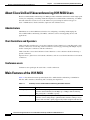
Cisco Unified Videoconferencing 3515 MCU Functionality
1-1
Introducing the Cisco Unified Videoconferencing 3515 MCU
1-1
About Cisco Unified Videoconferencing 3515 MCU Users
Administrators 1-2
Chair Controllers and Operators 1-2
Conference users 1-2
Main Features of the 3515 MCU
1-2
1-2
Port Capacities of the 3515 MCU12 and MCU24 1-5
Cisco Unified Videoconferencing 3515 MCU12 Port Capacity
Cisco Unified Videoconferencing 3515 MCU24 Port Capacity
About Cisco Unified Videoconferencing 3515 MCU Architecture
About Cisco Unified Videoconferencing 3515 MCU Topologies
Centralized Topology 1-7
Cascaded Conferences 1-7
1-5
1-5
1-6
1-7
Installation and Upgrade Guide for Cisco Unified Videoconferencing 3515 MCU12 and MCU24 Release 5.1
OL-11897-01
iii
Contents
CHAPTER
2
Setting Up Your Cisco Unified Videoconferencing 3515 MCU
2-1
Physical Description of the Cisco Unified Videoconferencing 3515 MCU
Preparing to Install the 3515 MCU
2-1
2-2
Verifying the Package Contents of the 3515 MCU
2-3
Mounting the Cisco Unified Videoconferencing 3515 MCU Unit in a 19-inch Rack
2-4
Cisco Unified Videoconferencing 3515 MCU Unit Initial Configuration 2-5
Connecting to a PC 2-5
Setting the IP Address 2-6
Connecting the Cisco Unified Videoconferencing 3515 MCU Unit to the LAN
2-8
Video Processing Module Initial Configuration for the 3515 MCU 2-8
Accessing the Video Processing Module Main Menu 2-8
Setting the IP Address 2-9
Setting Ethernet Speed and Duplex Parameters 2-9
Changing the Configuration Software Password 2-10
Changing the Security Level 2-11
Pointing the EMP to the Controlling Cisco Unified Videoconferencing 3515 MCU
Changing Advanced Configuration Settings 2-12
Saving Network Configuration Settings 2-13
Managing and Monitoring the Cisco Unified Videoconferencing 3515 MCU Unit
SNMP Management 2-13
Local Port Monitoring Connections 2-13
Performing Software Upgrades 2-14
2-13
Accessing the Cisco Unified Videoconferencing 3515 MCU Administrator Interface
Registering the Online Help for the 3515 MCU
Netscape Navigator Users 2-15
CHAPTER
3
Using the Cisco Software Upgrade Utility
Introduction
2-15
3-1
Upgrading Software
4
3-1
3-2
Cisco Unified Videoconferencing 3515 MCU Cable Connections and Pin-outs
Unit RS-232 9-Pin Serial Port on the 3515 MCU
RJ-45 8-Pin IP Network Port on the 3515 MCU
CHAPTER
5
2-14
3-1
Launching the Cisco Software Upgrade Utility
CHAPTER
2-11
4-1
4-2
Cisco Unified Videoconferencing 3515 MCU Technical Specifications
Technical Specifications Table for the 3515 MCU
4-1
5-1
5-1
Installation and Upgrade Guide for Cisco Unified Videoconferencing 3515 MCU12 and MCU24 Release 5.1
iv
OL-11897-01
Contents
CHAPTER
CHAPTER
6
7
Cisco Unified Videoconferencing 3515 MCU Safety
Electrical Safety for the 3515 MCU
Grounding 6-1
High Voltage 6-2
6-1
ESD Procedures for the 3515 MCU
6-2
6-1
Cisco Unified Videoconferencing 3515 MCU Compliance and Certifications
Safety Compliance for the 3515 MCU
EMC for the 3515 MCU
FCC Part 15 Notice
7-1
7-1
7-1
7-2
Telecom for the 3515 MCU 7-2
ACTA Part 68 Notice 7-2
Industry Canada 7-3
Environmental Compliance for the 3515 MCU
7-4
INDEX
Installation and Upgrade Guide for Cisco Unified Videoconferencing 3515 MCU12 and MCU24 Release 5.1
OL-11897-01
v
Contents
Installation and Upgrade Guide for Cisco Unified Videoconferencing 3515 MCU12 and MCU24 Release 5.1
vi
OL-11897-01
Preface
Revised: November 27, 2006, OL-11897-01
Purpose
This guide describes how to install and upgrade the Cisco Unified Videoconferencing 3515 MCU12 and
the Cisco Unified Videoconferencing 3515 MCU24 unit.
Audience
This guide is intended for network administrators who need instructions about how to install and upgrade
the Cisco Unified Videoconferencing 3515 MCU unit.
Organization
This manual is organized as follows:
Chapter
Description
Chapter 1, “Cisco Unified
Videoconferencing 3515 MCU
Functionality”
Provides a general overview of Cisco Unified
Videoconferencing 3515 MCU products, features, and network
architecture.
Chapter 2, “Setting Up Your
Cisco Unified
Videoconferencing 3515 MCU”
Describes how to install the Cisco Unified
Videoconferencing 3515 MCU, how to use the Administrator
interface to configure board settings and add Cisco Unified
Videoconferencing 3515 MCU users.
Chapter 3, “Using the Cisco
Software Upgrade Utility”
Describes how to use the Cisco Software Upgrade Utility
Chapter 4, “Cisco Unified
Videoconferencing 3515 MCU
Cable Connections and Pin-outs”
Describes the pin-to-pin and pin-out configurations of the
connectors and cables of the Cisco Unified
Videoconferencing 3515 MCU
Installation and Upgrade Guide for Cisco Unified Videoconferencing 3515 MCU12 and MCU24 Release 5.1
OL-11897-01
vii
Preface
Chapter
Description
Chapter 5, “Cisco Unified
Videoconferencing 3515 MCU
Technical Specifications”
Describes the technical specifications for the Cisco Unified
Videoconferencing 3515 MCU.
Chapter 6, “Cisco Unified
Videoconferencing 3515 MCU
Safety”
Describes safety procedures and requirements for operating the
Cisco Unified Videoconferencing 3515 MCU.
Chapter 7, “Cisco Unified
Videoconferencing 3515 MCU
Compliance and Certifications”
Provides certifications that have been approved for the
Cisco Unified Videoconferencing 3515 MCU.
Document Conventions
This document uses the following conventions:
Convention
Description
boldface font
Commands and keywords are in boldface.
italic font
Arguments for which you supply values are in italics.
[ ]
Elements in square brackets are optional.
{x|y|z}
Alternative keywords are grouped in braces and separated by vertical bars.
[x|y|z]
Optional alternative keywords are grouped in brackets and separated by
vertical bars.
string
A nonquoted set of characters. Do not use quotation marks around the string
or the string will include the quotation marks.
screen
font
Terminal sessions and information the system displays are in screen font.
boldface screen
font
Information you must enter is in boldface screen font.
italic screen font
Arguments for which you supply values are in italic screen font.
^
The symbol ^ represents the key labeled Control—for example, the key
combination ^D in a screen display means hold down the Control key while
you press the D key.
< >
Nonprinting characters, such as passwords are in angle brackets.
Obtaining Documentation
Cisco documentation and additional literature are available on Cisco.com. This section explains the
product documentation resources that Cisco offers.
Cisco.com
You can access the most current Cisco documentation at this URL:
http://www.cisco.com/techsupport
Installation and Upgrade Guide for Cisco Unified Videoconferencing 3515 MCU12 and MCU24 Release 5.1
viii
OL-11897-01
Preface
You can access the Cisco website at this URL:
http://www.cisco.com
You can access international Cisco websites at this URL:
http://www.cisco.com/public/countries_languages.shtml
Product Documentation DVD
The Product Documentation DVD is a library of technical product documentation on a portable medium.
The DVD enables you to access installation, configuration, and command guides for Cisco hardware and
software products. With the DVD, you have access to the HTML documentation and some of the
PDF files found on the Cisco website at this URL:
http://www.cisco.com/univercd/home/home.htm
The Product Documentation DVD is created and released regularly. DVDs are available singly or by
subscription. Registered Cisco.com users can order a Product Documentation DVD (product number
DOC-DOCDVD= or DOC-DOCDVD=SUB) from Cisco Marketplace at the Product Documentation
Store at this URL:
http://www.cisco.com/go/marketplace/docstore
Ordering Documentation
You must be a registered Cisco.com user to access Cisco Marketplace. Registered users may order
Cisco documentation at the Product Documentation Store at this URL:
http://www.cisco.com/go/marketplace/docstore
If you do not have a user ID or password, you can register at this URL:
http://tools.cisco.com/RPF/register/register.do
Documentation Feedback
You can provide feedback about Cisco technical documentation on the Cisco Technical Support &
Documentation site area by entering your comments in the feedback form available in every online
document.
Cisco Product Security Overview
Cisco provides a free online Security Vulnerability Policy portal at this URL:
http://www.cisco.com/en/US/products/products_security_vulnerability_policy.html
From this site, you will find information about how to do the following:
•
Report security vulnerabilities in Cisco products
•
Obtain assistance with security incidents that involve Cisco products
•
Register to receive security information from Cisco
Installation and Upgrade Guide for Cisco Unified Videoconferencing 3515 MCU12 and MCU24 Release 5.1
OL-11897-01
ix
Preface
A current list of security advisories, security notices, and security responses for Cisco products is
available at this URL:
http://www.cisco.com/go/psirt
To see security advisories, security notices, and security responses as they are updated in real time, you
can subscribe to the Product Security Incident Response Team Really Simple Syndication (PSIRT RSS)
feed. Information about how to subscribe to the PSIRT RSS feed is found at this URL:
http://www.cisco.com/en/US/products/products_psirt_rss_feed.html
Reporting Security Problems in Cisco Products
Cisco is committed to delivering secure products. We test our products internally before we release them,
and we strive to correct all vulnerabilities quickly. If you think that you have identified a vulnerability
in a Cisco product, contact PSIRT:
•
For emergencies only — [email protected]
An emergency is either a condition in which a system is under active attack or a condition for which
a severe and urgent security vulnerability should be reported. All other conditions are considered
nonemergencies.
•
For nonemergencies — [email protected]
In an emergency, you can also reach PSIRT by telephone:
Tip
•
1 877 228-7302
•
1 408 525-6532
We encourage you to use Pretty Good Privacy (PGP) or a compatible product (for example, GnuPG) to
encrypt any sensitive information that you send to Cisco. PSIRT can work with information that has been
encrypted with PGP versions 2.x through 9.x.
Never use a revoked encryption key or an expired encryption key. The correct public key to use in your
correspondence with PSIRT is the one linked in the Contact Summary section of the Security
Vulnerability Policy page at this URL:
http://www.cisco.com/en/US/products/products_security_vulnerability_policy.html
The link on this page has the current PGP key ID in use.
If you do not have or use PGP, contact PSIRT to find other means of encrypting the data before sending
any sensitive material.
Product Alerts and Field Notices
Modifications to or updates about Cisco products are announced in Cisco Product Alerts and Cisco Field
Notices. You can receive Cisco Product Alerts and Cisco Field Notices by using the Product Alert Tool
on Cisco.com. This tool enables you to create a profile and choose those products for which you want to
receive information.
Installation and Upgrade Guide for Cisco Unified Videoconferencing 3515 MCU12 and MCU24 Release 5.1
x
OL-11897-01
Preface
To access the Product Alert Tool, you must be a registered Cisco.com user. (To register as a Cisco.com
user, go to this URL: http://tools.cisco.com/RPF/register/register.do) Registered users can access the
tool at this URL: http://tools.cisco.com/Support/PAT/do/ViewMyProfiles.do?local=en
Obtaining Technical Assistance
Cisco Technical Support provides 24-hour-a-day award-winning technical assistance. The
Cisco Technical Support & Documentation website on Cisco.com features extensive online support
resources. In addition, if you have a valid Cisco service contract, Cisco Technical Assistance Center
(TAC) engineers provide telephone support. If you do not have a valid Cisco service contract, contact
your reseller.
Cisco Technical Support & Documentation Website
The Cisco Technical Support & Documentation website provides online documents and tools for
troubleshooting and resolving technical issues with Cisco products and technologies. The website is
available 24 hours a day at this URL:
http://www.cisco.com/techsupport
Access to all tools on the Cisco Technical Support & Documentation website requires a Cisco.com
user ID and password. If you have a valid service contract but do not have a user ID or password, you
can register at this URL:
http://tools.cisco.com/RPF/register/register.do
Note
Use the Cisco Product Identification Tool to locate your product serial number before submitting a
request for service online or by phone. You can access this tool from the Cisco Technical Support &
Documentation website by clicking the Tools & Resources link, clicking the All Tools (A-Z) tab, and
then choosing Cisco Product Identification Tool from the alphabetical list. This tool offers three search
options: by product ID or model name; by tree view; or, for certain products, by copying and pasting
show command output. Search results show an illustration of your product with the serial number label
location highlighted. Locate the serial number label on your product and record the information before
placing a service call.
Tip
Displaying and Searching on Cisco.com
If you suspect that the browser is not refreshing a web page, force the browser to update the web page
by holding down the Ctrl key while pressing F5.
To find technical information, narrow your search to look in technical documentation, not the entire
Cisco.com website. On the Cisco.com home page, click the Advanced Search link under the Search box
and then click the Technical Support & Documentation radio button.
To provide feedback about the Cisco.com website or a particular technical document, click Contacts &
Feedback at the top of any Cisco.com web page.
Installation and Upgrade Guide for Cisco Unified Videoconferencing 3515 MCU12 and MCU24 Release 5.1
OL-11897-01
xi
Preface
Submitting a Service Request
Using the online TAC Service Request Tool is the fastest way to open S3 and S4 service requests. (S3 and
S4 service requests are those in which your network is minimally impaired or for which you require
product information.) After you describe your situation, the TAC Service Request Tool provides
recommended solutions. If your issue is not resolved using the recommended resources, your service
request is assigned to a Cisco engineer. The TAC Service Request Tool is located at this URL:
http://www.cisco.com/techsupport/servicerequest
For S1 or S2 service requests, or if you do not have Internet access, contact the Cisco TAC by telephone.
(S1 or S2 service requests are those in which your production network is down or severely degraded.)
Cisco engineers are assigned immediately to S1 and S2 service requests to help keep your business
operations running smoothly.
To open a service request by telephone, use one of the following numbers:
Asia-Pacific: +61 2 8446 7411
Australia: 1 800 805 227
EMEA: +32 2 704 55 55
USA: 1 800 553 2447
For a complete list of Cisco TAC contacts, go to this URL:
http://www.cisco.com/techsupport/contacts
Definitions of Service Request Severity
To ensure that all service requests are reported in a standard format, Cisco has established severity
definitions.
Severity 1 (S1)—An existing network is “down” or there is a critical impact to your business operations.
You and Cisco will commit all necessary resources around the clock to resolve the situation.
Severity 2 (S2)—Operation of an existing network is severely degraded, or significant aspects of your
business operations are negatively affected by inadequate performance of Cisco products. You and
Cisco will commit full-time resources during normal business hours to resolve the situation.
Severity 3 (S3)—Operational performance of the network is impaired while most business operations
remain functional. You and Cisco will commit resources during normal business hours to restore service
to satisfactory levels.
Severity 4 (S4)—You require information or assistance with Cisco product capabilities, installation, or
configuration. There is little or no effect on your business operations.
Obtaining Additional Publications and Information
Information about Cisco products, technologies, and network solutions is available from various online
and printed sources.
•
The Cisco Online Subscription Center is the website where you can sign up for a variety of
Cisco e-mail newsletters and other communications. Create a profile and then select the
subscriptions that you would like to receive. To visit the Cisco Online Subscription Center,
go to this URL:
http://www.cisco.com/offer/subscribe
Installation and Upgrade Guide for Cisco Unified Videoconferencing 3515 MCU12 and MCU24 Release 5.1
xii
OL-11897-01
Preface
•
The Cisco Product Quick Reference Guide is a handy, compact reference tool that includes brief
product overviews, key features, sample part numbers, and abbreviated technical specifications for
many Cisco products that are sold through channel partners. It is updated twice a year and includes
the latest Cisco channel product offerings. To order and find out more about the Cisco Product Quick
Reference Guide, go to this URL:
http://www.cisco.com/go/guide
•
Cisco Marketplace provides a variety of Cisco books, reference guides, documentation, and logo
merchandise. Visit Cisco Marketplace, the company store, at this URL:
http://www.cisco.com/go/marketplace/
•
Cisco Press publishes a wide range of general networking, training, and certification titles. Both new
and experienced users will benefit from these publications. For current Cisco Press titles and other
information, go to Cisco Press at this URL:
http://www.ciscopress.com
•
Internet Protocol Journal is a quarterly journal published by Cisco Systems for engineering
professionals involved in designing, developing, and operating public and private internets and
intranets. You can access the Internet Protocol Journal at this URL:
http://www.cisco.com/ipj
•
Networking products offered by Cisco Systems, as well as customer support services, can be
obtained at this URL:
http://www.cisco.com/en/US/products/index.html
•
Networking Professionals Connection is an interactive website where networking professionals
share questions, suggestions, and information about networking products and technologies with
Cisco experts and other networking professionals. Join a discussion at this URL:
http://www.cisco.com/discuss/networking
•
“What’s New in Cisco Documentation” is an online publication that provides information about the
latest documentation releases for Cisco products. Updated monthly, this online publication is
organized by product category to direct you quickly to the documentation for your products. You
can view the latest release of “What’s New in Cisco Documentation” at this URL:
http://www.cisco.com/univercd/cc/td/doc/abtunicd/136957.htm
•
World-class networking training is available from Cisco. You can view current offerings at
this URL:
http://www.cisco.com/en/US/learning/index.html
Installation and Upgrade Guide for Cisco Unified Videoconferencing 3515 MCU12 and MCU24 Release 5.1
OL-11897-01
xiii
Preface
Installation and Upgrade Guide for Cisco Unified Videoconferencing 3515 MCU12 and MCU24 Release 5.1
xiv
OL-11897-01
C H A P T E R
1
Cisco Unified Videoconferencing 3515 MCU
Functionality
This section describes the following topics:
•
Introducing the Cisco Unified Videoconferencing 3515 MCU, page 1-1
•
About Cisco Unified Videoconferencing 3515 MCU Users, page 1-2
•
Main Features of the 3515 MCU, page 1-2
•
Port Capacities of the 3515 MCU12 and MCU24, page 1-5
•
About Cisco Unified Videoconferencing 3515 MCU Architecture, page 1-6
•
About Cisco Unified Videoconferencing 3515 MCU Topologies, page 1-7
Introducing the Cisco Unified Videoconferencing 3515 MCU
The Cisco Unified Videoconferencing 3515 MCU enables multimedia, multiparty collaboration in
applications such as group conferencing, distance learning, training and video telephony. The
Cisco Unified Videoconferencing 3515 MCU supports multimedia, multiparty communications in the
board room, at the desktop, in the home, or on the road over wireless.
The Cisco Unified Videoconferencing 3515 MCU provides core IP-centric functionality, a wide range
of layouts, powerful audio and video transcoding, an open API for customer application development,
support of web-initiated data collaboration, and software upgradeable technology. Services are
pre-configured so that they suit most conferencing requirements. However, when necessary,
administrators can create customized services to suit their networks and user needs.
Installation and Upgrade Guide for Cisco Unified Videoconferencing 3515 MCU12 and MCU24 Release 5.1
OL-11897-01
1-1
Chapter 1
Cisco Unified Videoconferencing 3515 MCU Functionality
About Cisco Unified Videoconferencing 3515 MCU Users
About Cisco Unified Videoconferencing 3515 MCU Users
The Cisco Unified Videoconferencing 3515 MCU provides an intuitive web interface with a single point
of entry for configuring, controlling and monitoring the Cisco Unified Videoconferencing 3515 MCU
unit and conference sessions. Access to the interfaces is password-protected for four types of
users—Administrators, Chair Controllers, Operators and conference users.
Administrators
Administrators use the Administrator interface for configuring, controlling and managing the
Cisco Unified Videoconferencing 3515 MCU, conference services and supporting devices and
applications.
Chair Controllers and Operators
Chair Controllers and Operators can use the Conference Control interface for controlling audio, video
and data connections, for selecting advanced conference view image positioning and multiple layouts,
and for creating new conferences and sub-conferences.
Chair Controllers can use the Conference Control interface to view conference details and manage a
specific conference.
Operators have a global view of all current conferences, and can act as Chair Controllers for all current
conferences.
Conference users
Conference users participate in actual video or audio conferences.
Main Features of the 3515 MCU
Table 1-1 lists the main features provided by the Cisco Unified Videoconferencing 3515 MCU for
effective audio and videoconferencing and a satisfying user experience.
Table 1-1
Summary of Cisco Unified Videoconferencing 3515 MCU Features
Feature
Description
Flat capacity
Each conference participant can connect with his or her own optimal codec,
resolution and bandwidth (from 64 Kbps up to 2 Mbps) without affecting
other participants or the MCU capacity.
Superior video quality
Video and audio processing is carried out per user rather than per conference.
Each user connects using unique, optimized audio and video settings to enjoy
the best audio and video quality supported by his/her endpoint and network.
Installation and Upgrade Guide for Cisco Unified Videoconferencing 3515 MCU12 and MCU24 Release 5.1
1-2
OL-11897-01
Chapter 1
Cisco Unified Videoconferencing 3515 MCU Functionality
Main Features of the 3515 MCU
Table 1-1
Summary of Cisco Unified Videoconferencing 3515 MCU Features (continued)
Feature
Description
Seamless
interoperability
The Cisco Unified Videoconferencing 3515 MCU is built on the strong
foundation of the Cisco H.323 and SIP software, ensuring full compliance
and unmatched interoperability with IP and ISDN networks.
The MCU enables H.323, SIP and SCCP devices to participate in the same
conference session.
When used with the Cisco Unified Videoconferencing 3500 Gateway, the
MCU also enables ISDN and V.35 wireless devices to participate in the same
conference session.
Intuitive web-based
management and
control
Supported protocols
Both the Cisco Unified Videoconferencing 3515 MCU system and actual
conference sessions are managed, configured, and dynamically modified
through an intuitive, web-based interface that offers easy, high-level
conference control and administrative flexibility for an enhanced user
experience.
•
H.323 version 4
•
SIP RFC 3261 for the Session Initiation Protocol
•
SCCP
•
H.243 for conference control
•
RFC 2833 for in-band DTMF with SIP
•
H.281 for far end camera control (FECC)
•
H.235 for IP-based media encryption
•
H.239 for standard simultaneous transmission of live video and
presentation sharing feeds.
•
SDP (RFC 3264, 2327)
•
T.120
•
H.320 (when using a gateway)
Note
Audio transcoding
codecs
The Cisco Unified Videoconferencing 3515 MCU supports calls
from H.323 and SIP endpoints in the same conference. Call
signalling is handled on all ports regardless of the protocol type.
•
G.711 A/µ Law
•
G.722
•
G.722.1
•
G.723.1
•
G.728
•
G.729 A and B
Installation and Upgrade Guide for Cisco Unified Videoconferencing 3515 MCU12 and MCU24 Release 5.1
OL-11897-01
1-3
Chapter 1
Cisco Unified Videoconferencing 3515 MCU Functionality
Main Features of the 3515 MCU
Table 1-1
Summary of Cisco Unified Videoconferencing 3515 MCU Features (continued)
Feature
Description
Unmatched video
quality
The Cisco Unified Videoconferencing 3515 MCU delivers exceptionally
high quality video and audio processing, using latest industry standards and
leveraging upon advanced software upgradeable DSP chips. The Cisco
QualiVision feature provides highly improved, standard-based video quality
for networks with packet loss, assuring best video quality at all times.
The Cisco Unified Videoconferencing 3515 MCU achieves the best video
quality by supporting the following video capabilities:
•
H.261, H.263 and H.264 in the same conference
•
A choice of 26 Continuous Presence layouts
•
Up to 2 Mbps on each stream without affecting capacity
•
QCIF, CIF and 4CIF in the same conference without affecting capacity
•
VGA, SVGA, XGA (supported for presentation channel only)
Multi-view (Dual
Video)
Supports dual-screen video and data transmissions to endpoints supporting
two monitors using the H.239 standard or TANDBERG DuoVideo. One
monitor receives the conference video image and the other screen displays a
presentation.
T.120 Data
Collaboration support
Data collaboration is defined by the T.120 standard. Data collaboration using
T.120 over the video conference connection enhances the conference by
providing the tools for conference participants to share data instantaneously.
Security and privacy
•
Administrator and operator password protection for accessing the
Cisco Unified Videoconferencing 3515 MCU web interfaces.
•
Optional PIN protection for joining a conference and web access.
•
Additional PIN protection for conference Chair Control.
•
The Cisco Unified Videoconferencing 3515 MCU uses H.235-based
encryption to achieve secure communication with endpoints that support
this standard.
In-conference control
using DTMF or H.243
During a conference, participants may use their endpoint remote control or
keypad to perform actions such as mute, volume control, changing video
layouts and inviting participants. Users interact with the Cisco Unified
Videoconferencing 3515 MCU via DTMF signaling or the onscreen GUI of
H.243-compliant endpoints.
Optional no self see
The administrator can configure the Cisco Unified
Videoconferencing 3515 MCU service to remove the self-view for each
conference participant. This feature enables more effective use of the video
screen.
IVR messages
The Cisco Unified Videoconferencing 3515 MCU includes pre-recorded
greetings to conference participants and announcements as each new
participant joins the conference. Using the Cisco Audio Message Utility,
IVR messages can be recorded to provide custom greetings and
announcements.
Installation and Upgrade Guide for Cisco Unified Videoconferencing 3515 MCU12 and MCU24 Release 5.1
1-4
OL-11897-01
Chapter 1
Cisco Unified Videoconferencing 3515 MCU Functionality
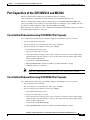
Port Capacities of the 3515 MCU12 and MCU24
Port Capacities of the 3515 MCU12 and MCU24
The Cisco Unified Videoconferencing 3515 MCU12 and Cisco Unified
Videoconferencing 3515 MCU24 are delivered with a predetermined number of ports.
The Cisco Unified Videoconferencing 3545 MCU supports switched High Definition (HD) video
service types. HD services enable Voice Activated single-screen displays at up to 2 Mbps, and offer
resolutions of 1280 x 720 pixels (720p) and 1920 x 1080 pixels (1080p).
HD service types also enable you to set a minimum downspeeding bandwidth rate which is common to
all endpoints participating in a conference.
Cisco Unified Videoconferencing 3515 MCU12 Port Capacity
Cisco Unified Videoconferencing 3515 MCU12 supports a fixed number of ports as follows:
•
72 ports of fully transcoded audio.
•
18 ports of fully processed standard rate video (up to 384 Kbps)
•
12 ports of fully processed high rate video (up to 2Mbps).
– Any Continuous Presence layout.
– All ports are fully video processed.
– Video and audio processing per user, not per conference. Each user connects using unique,
optimized audio and video settings to enjoy the best audio and video quality supported by
his/her endpoint and network.
– Any mixture of H.261/H.263/H.264.
– Mixed QCIF/CIF/4CIF conferences (4CIF is provided with H.263 at 15fps).
– Unlimited number of conferences.
Note
When using a High Definition Video service type, only a single screen is available.
Cisco Unified Videoconferencing 3515 MCU24 Port Capacity
Cisco Unified Videoconferencing 3515 MCU24 supports a fixed number of ports as follows:
•
72 ports of fully transcoded audio.
•
36 ports of fully processed standard rate video (up to 384 Kbps)
•
24 ports of fully processed high rate video (up to 2Mbps).
– Any Continuous Presence layout.
– All ports are fully video processed.
– Video and audio processing per user, not per conference. Each user connects using unique,
optimized audio and video settings to enjoy the best audio and video quality supported by
his/her endpoint and network.
– Any mixture of H.261/H.263/H.264;
– Mixed QCIF/CIF/4CIF conferences (4CIF is provided with H.263 at 15fps).
Installation and Upgrade Guide for Cisco Unified Videoconferencing 3515 MCU12 and MCU24 Release 5.1
OL-11897-01
1-5
Chapter 1
Cisco Unified Videoconferencing 3515 MCU Functionality
About Cisco Unified Videoconferencing 3515 MCU Architecture
– Unlimited number of conferences.
Note
When using a High Definition Video service type, only a single screen is available.
About Cisco Unified Videoconferencing 3515 MCU Architecture
The Cisco Unified Videoconferencing 3515 MCU enables both voice-only and video conference calls
for H.323, SIP, H.320, SCCP and regular PSTN network telephones. H.323 and SIP devices can connect
to a conference directly through the Cisco Unified Videoconferencing 3515 MCU. Other devices such
as voice telephones and video conferencing terminals (H.320) can connect to a conference via a gateway,
such as the Cisco Unified Videoconferencing 3500 Gateway.
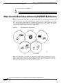
Figure 1-1
Supported Devices and Protocols
IP - H323.
MCU, Gateway
ISDN - H323.
SIP
3G - H324.M
157148
IP
The Cisco Unified Videoconferencing 3515 MCU supports devices that can send and receive video
streams, as well as those that cannot send but only receive video streams. This means that terminals
without a video camera or video capturing capabilities can participate in a conference as voice-only
participants while benefiting from seeing the other participants.
Installation and Upgrade Guide for Cisco Unified Videoconferencing 3515 MCU12 and MCU24 Release 5.1
1-6
OL-11897-01
Chapter 1
Cisco Unified Videoconferencing 3515 MCU Functionality
About Cisco Unified Videoconferencing 3515 MCU Topologies
About Cisco Unified Videoconferencing 3515 MCU Topologies
The Cisco Unified Videoconferencing 3515 MCU can work in a centralized or cascaded topology. This
section describes these two options.
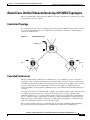
Centralized Topology
In a centralized topology, the Cisco Unified Videoconferencing 3515 MCU performs media processing
for all connected terminals. The Cisco Unified Videoconferencing 3515 MCU can handle multiple
conferences simultaneously.
Figure 1-2
Centralized Topology
Headquarters
MCU
MCU
MCU
Site 2
200844
Site 1
Cascaded Conferences
The Cisco Unified Videoconferencing 3515 MCU allows you to combine two or more conferences
resulting in a larger conference with many more participants. This is called cascading. Cascading creates
a distributed environment that helps reduce the drain on network resources. In addition, the processing
resources required by the Cisco Unified Videoconferencing 3515 MCU are distributed between
participating MCUs. Costly telephone or ISDN line usage can be further reduced with the mediation of
a gateway.
Cascading occurs when one conference with “x” number of participants invites another conference with
“y” number of participants. The two conferences effectively become one large conference. The
bandwidth required across a cascaded conference link is only that of one audio/video stream between
the two conferences. This is significantly less than the accumulated bandwidth of all the participants.
Each separate Cisco Unified Videoconferencing 3515 MCU unit participating in a conference retains
control of its individual conference resources and participants.
The cascaded conference in Figure 1-3 minimizes the use of network bandwidth while distributing
processing among the participating the Cisco Unified Videoconferencing 3515 MCU units.
Installation and Upgrade Guide for Cisco Unified Videoconferencing 3515 MCU12 and MCU24 Release 5.1
OL-11897-01
1-7
Chapter 1
Cisco Unified Videoconferencing 3515 MCU Functionality
About Cisco Unified Videoconferencing 3515 MCU Topologies
Figure 1-3
Cascaded Conference
Headquarters
MCU
Site 2
MCU
MCU
200845
Site 1
Installation and Upgrade Guide for Cisco Unified Videoconferencing 3515 MCU12 and MCU24 Release 5.1
1-8
OL-11897-01
C H A P T E R
2
Setting Up Your Cisco Unified
Videoconferencing 3515 MCU
This section describes the following topics:
•
Physical Description of the Cisco Unified Videoconferencing 3515 MCU, page 2-1
•
Preparing to Install the 3515 MCU, page 2-2
•
Verifying the Package Contents of the 3515 MCU, page 2-3
•
Mounting the Cisco Unified Videoconferencing 3515 MCU Unit in a 19-inch Rack, page 2-4
•
Cisco Unified Videoconferencing 3515 MCU Unit Initial Configuration, page 2-5
•
Video Processing Module Initial Configuration for the 3515 MCU, page 2-8
•
Managing and Monitoring the Cisco Unified Videoconferencing 3515 MCU Unit, page 2-13
•
Accessing the Cisco Unified Videoconferencing 3515 MCU Administrator Interface, page 2-14
•
Registering the Online Help for the 3515 MCU, page 2-15
Physical Description of the Cisco Unified
Videoconferencing 3515 MCU
Each Cisco Unified Videoconferencing 3515 MCU unit internally contains two cards:
•
Signaling and audio card (MCU—the upper card)
•
Video processing card (EMP—the lower card)
The two cards work together to perform audio and videoconferencing, but each card requires a unique
IP address. The cards communicate with each other using IP as the backbone.
Note
For correct operation, the EMP card must register with the MCU.
This section provides a physical description of the Cisco Unified Videoconferencing 3515 MCU12 and
Cisco Unified Videoconferencing 3515 MCU24 units.
The Cisco Unified Videoconferencing 3515 MCU unit has a 10/100BaseT Ethernet port on the front
panel that uses an RJ-45 connector to connect to the network. There is an asynchronous, 9-pin serial-port
that you can use with a hyperterminal program to configure and monitor the module.
Installation and Upgrade Guide for Cisco Unified Videoconferencing 3515 MCU12 and MCU24 Release 5.1
OL-11897-01
2-1
Chapter 2
Setting Up Your Cisco Unified Videoconferencing 3515 MCU
Preparing to Install the 3515 MCU
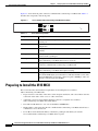
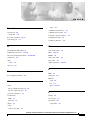
Figure 2-1 shows the front panel of the Cisco Unified Videoconferencing 3515 MCU unit. Table 2-1
describes the components of the front panel.
Cisco Unified Videoconferencing 3515 MCU Front Panel
GK Reg CPU Hight
SERIAL
RST
10/100 Base T
ALARM ACT
MC
SERIAL
CPU Hight
157265
Figure 2-1
PWR
10/100 Base T
Table 2-1
RST
ALARM ACT
Front Panel Components
Component
Description
10/100 BaseT connector An RJ-45 connector that provides the primary Ethernet connection for the IP
network port.
Serial connector
A DB-9 connector that allows you to connect a PC terminal for local
configuration.
RST button
Allows you to reset the Cisco Unified Videoconferencing 3515 MCU unit
manually.
GK Reg and MC LEDs
Lights green when the Cisco Unified Videoconferencing 3515 MCU unit is
registered with a gatekeeper.
CPU High LED
Lights green when more than 50% of the Cisco Unified
Videoconferencing 3515 MCU unit resources are in use.
ACT LED
Lights green to indicate that there is at least one currently active conference
on the Cisco Unified Videoconferencing 3515 MCU unit.
ALARM LED
Lights green to indicate that an error has occurred and the Cisco Unified
Videoconferencing 3515 MCU unit requires resetting.
10/100 BaseT LEDs
The top part of the 10/100 BaseT connector contains two LED indicators.
The left-hand LED lights green when the local IP network link is active. The
right-hand LED lights green if the connection speed is 100 Mbps, and is off
when the connection speed is 10 Mbps.
Preparing to Install the 3515 MCU
This section describes the installation requirements for installing the Cisco Unified
Videoconferencing 3515 MCU unit.
•
Proper clearance at the sides of the unit to allow adequate ventilation, and at least 20 cm clearance
at the back of the unit to allow access to cable connections
•
A PC with a serial port and terminal emulation software to assign the Cisco Unified
Videoconferencing 3515 MCU unit an IP address
•
Two dedicated IP addresses—one each for the MCU and EMP units
•
The IP address of the router that the Cisco Unified Videoconferencing 3515 MCU unit will use to
communicate across the network
•
For an H.323 environment, IP address of the H.323 gatekeeper with which you want the
Cisco Unified Videoconferencing 3515 MCU unit to register
Installation and Upgrade Guide for Cisco Unified Videoconferencing 3515 MCU12 and MCU24 Release 5.1
2-2
OL-11897-01
Chapter 2
Setting Up Your Cisco Unified Videoconferencing 3515 MCU
Verifying the Package Contents of the 3515 MCU
•
For a Skinny Client Control Protocol (SCCP) environment, the IP address of the Trivial File Transfer
Protocol (TFTP) server or Cisco Unified CallManager from which you want the Cisco Unified
Videoconferencing 3515 MCU unit to get configuration information
•
Available IP network ports on the switch for the Cisco Unified Videoconferencing 3515 MCU unit
•
A grounded AC power outlet
•
A 10BaseT or 100BaseT LAN cable
•
Ambient room temperature range of 32o to 104oF (0o to 40oC)
•
Non-condensing relative humidity range of 5% to 90%
Verifying the Package Contents of the 3515 MCU
Inspect the contents of the box for shipping damage. Report any damage or missing items to your Cisco
representative. Table 2-2 lists the package contents for the Cisco Unified Videoconferencing 3515 MCU
unit.
Table 2-2
Package Contents with Cisco Unified Videoconferencing 3515 MCU12 or
Cisco Unified Videoconferencing 3515 MCU24 Unit
Product
Cisco Unified
Videoconferencing
3515 MCU unit
Contents
•
Cisco Unified Videoconferencing 3515 MCU12 or Cisco Unified
Videoconferencing 3515 MCU24 unit
•
Power cable (depending on customer location)
•
Terminal cable
•
Two LAN cables (one for the MCU, one for the video processing module)
•
Rack mounting kit (two brackets and six screws)
•
Four rubber feet
•
Guide to Cisco Conferencing Documentation
•
Regulatory Compliance and Safety Information for Cisco Unified
Videoconferencing 3500 Products
•
Cisco Unified Videoconferencing Software CD-ROM
•
Cisco Information Package
Installation and Upgrade Guide for Cisco Unified Videoconferencing 3515 MCU12 and MCU24 Release 5.1
OL-11897-01
2-3
Chapter 2
Setting Up Your Cisco Unified Videoconferencing 3515 MCU
Mounting the Cisco Unified Videoconferencing 3515 MCU Unit in a 19-inch Rack
Mounting the Cisco Unified Videoconferencing 3515 MCU Unit
in a 19-inch Rack
You can optionally mount the Cisco Unified Videoconferencing 3515 MCU unit in a standard 19-inch
rack. Two mounting brackets and a set of screws are included in the Cisco Unified
Videoconferencing 3515 MCU unit shipping box.
Procedure
Step 1
Disconnect all cables including the power cables.
Step 2
Place the Cisco Unified Videoconferencing 3515 MCU unit right-side up on a hard flat surface, with the
front panel facing you.
Step 3
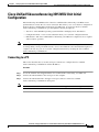
Position a mounting bracket over the mounting holes on each side of the Cisco Unified
Videoconferencing 3515 MCU unit, as shown in Figure 2-2.
Fitting a Bracket for Rack Mounting
157263
Figure 2-2
Step 4
Pass the screws through the brackets and tighten them into the screw holes on each side of the
Cisco Unified Videoconferencing 3515 MCU unit using a suitable screwdriver.
Step 5
Insert the Cisco Unified Videoconferencing 3515 MCU unit into the 19-inch rack.
Step 6
Fasten the brackets to the side rails of the rack.
Step 7
Make sure that the air vents at the sides of the Cisco Unified Videoconferencing 3515 MCU unit are not
blocked.
Installation and Upgrade Guide for Cisco Unified Videoconferencing 3515 MCU12 and MCU24 Release 5.1
2-4
OL-11897-01
Chapter 2
Setting Up Your Cisco Unified Videoconferencing 3515 MCU
Cisco Unified Videoconferencing 3515 MCU Unit Initial Configuration
Cisco Unified Videoconferencing 3515 MCU Unit Initial
Configuration
Initial monitoring and administration of the Cisco Unified Videoconferencing 3515 MCU unit are
performed from a remote PC via a serial connection. This allows you to access the boot configuration
menu of the Cisco Unified Videoconferencing 3515 MCU unit. At power-up, the Cisco Unified
Videoconferencing 3515 MCU unit goes through the following boot phases:
Note
•
Auto-boot—The embedded operating system initializes and displays basic information.
•
Configuration menu—A six-second countdown allows you to enter the configuration menu.
•
Initialization—The Cisco Unified Videoconferencing 3515 MCU unit completes its boot sequence
and is ready for operation.
You can perform serial port configuration of the Cisco Unified Videoconferencing 3515 MCU unit only
at startup, during a short period indicated by a six-second countdown. Once the initialization phase is
complete, the only way you can access the configuration menu is by restarting the Cisco Unified
Videoconferencing 3515 MCU unit.
Connecting to a PC
This section describes how to use the serial port connection to configure the Cisco Unified
Videoconferencing 3515 MCU unit with an IP address.
Procedure
Step 1
Locate the terminal cable shipped with the Cisco Unified Videoconferencing 3515 MCU unit.
Step 2
Connect the end labeled PC to the serial port on the computer.
Step 3
Connect the end labeled Unit to the upper serial port connector on the Cisco Unified
Videoconferencing 3515 MCU unit front panel.
Note
The PC terminal should have an installed terminal emulation application, such as HyperTerminal.
Installation and Upgrade Guide for Cisco Unified Videoconferencing 3515 MCU12 and MCU24 Release 5.1
OL-11897-01
2-5
Chapter 2
Setting Up Your Cisco Unified Videoconferencing 3515 MCU
Cisco Unified Videoconferencing 3515 MCU Unit Initial Configuration
Setting the IP Address
This section describes how to use the serial port to configure the unit with an IP address and other
address information.
The upper serial port on the Cisco Unified Videoconferencing 3515 MCU unit front panel is used to
assign a new IP address to your Cisco Unified Videoconferencing 3515 MCU unit. You can assign the
IP address before or after you connect the hardware to the network.
Before You Begin
Gather the items listed in Table 2-3 to assign an IP address to the Cisco Unified
Videoconferencing 3515 MCU unit.
Table 2-3
Requirements for Setting the IP Address
Requirements
Notes
Dedicated IP address for the Cisco Unified
Videoconferencing 3515 MCU unit
IP address of the default router the Cisco Unified
Videoconferencing 3515 MCU unit uses to
communicate over the network
Subnet mask for the Cisco Unified
Videoconferencing 3515 MCU unit if applicable
Domain Name Server and domain name for
Cisco Unified Videoconferencing 3515 MCU unit
if applicable
PC with available serial port and terminal
emulator software installed
RS-232 terminal cable (shipped with the unit)
Procedure
Step 1
Connect the RS-232 terminal cable to the PC terminal.
Step 2
Connect the power cable.
Step 3
Start the terminal emulation application on the PC.
Step 4
Set the communication settings in the terminal emulation application on the PC as follows:
– Baud rate: 9600
– Data bits: 8
– Parity: None
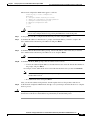
– Stop bits: 1
– Flow control: None
Step 5
Turn on the power to the Cisco Unified Videoconferencing 3515 MCU unit.
A log of the auto-boot events appears on the computer.
Step 6
When the message “Press any key to start configuration” appears on the screen, press any key within six
seconds.
Installation and Upgrade Guide for Cisco Unified Videoconferencing 3515 MCU12 and MCU24 Release 5.1
2-6
OL-11897-01
Chapter 2
Setting Up Your Cisco Unified Videoconferencing 3515 MCU
Cisco Unified Videoconferencing 3515 MCU Unit Initial Configuration
The network configuration Main menu appears as follows:
Press any key to start configuration...
Main menu
N: Configure default network port values
P: Change the configuration software password
S: Configure network security level
A: Advanced configuration menu
Q: Quit
Select:
If you do not press a key before the countdown ends, the device continues its initialization and
you can only configure the device by pressing the RST button on the front panel.
Caution
Step 7
At the prompt, enter N to configure default network port values and press Enter.
Step 8
At the Enter IP address for Interface No. 1 prompt, enter the IP address you want to assign to the
Cisco Unified Videoconferencing 3515 MCU unit and press Enter.
Do not use leading zeros in the IP address.
Caution
Step 9
At the Enter Default Router IP Address prompt, enter the IP address of the router that you want the
Cisco Unified Videoconferencing 3515 MCU unit to use and press Enter.
Do not use leading zeros in the IP address.
Caution
Step 10
At the Enter IP Mask (HEX) prompt, enter the subnet mask as follows:
– Convert the subnet mask IP address to hexadecimal notation, enter the hexadecimal number at
the prompt, and press Enter.
For example, for the subnet mask 255.255.255.0 the hexadecimal value you enter is FFFFFF00.
Note
You can use the desktop calculator on your computer to convert the subnet mask ID to
hexadecimal notation.
– If a subnet mask is not used, press Enter.
After you enter the subnet mask parameter, the unit updates the boot line parameter and reboots.
Step 11
Caution
At the network configuration Main menu, enter Q to save your changes and allow the device to complete
the boot process.
Configuration of any of the parameters other than N: Configure default network port values may alter
the function of the device and should not be performed by an unauthorized person.
Installation and Upgrade Guide for Cisco Unified Videoconferencing 3515 MCU12 and MCU24 Release 5.1
OL-11897-01
2-7
Chapter 2
Setting Up Your Cisco Unified Videoconferencing 3515 MCU
Video Processing Module Initial Configuration for the 3515 MCU
Connecting the Cisco Unified Videoconferencing 3515 MCU Unit to the LAN
This section describes how to connect the Cisco Unified Videoconferencing 3515 MCU unit to the Local
Area Network (LAN).
Procedure
Step 1
Connect the supplied LAN cable from your network hub to the 10/100BaseT Ethernet port on the front
panel of the Cisco Unified Videoconferencing 3515 MCU unit. The 10/100BaseT port accepts an RJ-45
connector.
Step 2
Turn on the power to the Cisco Unified Videoconferencing 3515 MCU unit.
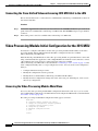
Video Processing Module Initial Configuration for the 3515 MCU
You must also configure an IP address for the video processing module. The IP address of the video
processing module must be different than the IP address configured for the Cisco Unified
Videoconferencing 3515 MCU unit.
Initial monitoring and administration of the video processing module are performed from a remote PC
using a terminal emulation application, such as HyperTerminal. To make the serial connection, connect
a PC terminal to the lower serial port on the front panel of the Cisco Unified
Videoconferencing 3515 MCU unit as described in the “Connecting to a PC” section on page 2-5. The
serial configuration utility runs as a target configuration service. You can use the serial configuration
utility to:
•
Configure default network port values.
•
Modify the configuration software password.
•
Modify the Cisco Unified Videoconferencing 3515 MCU unit IP address.
•
Modify advanced configuration settings such as the web server port and LAN port, and to restore
the factory configuration.
Accessing the Video Processing Module Main Menu
You access the video processing module Main configuration menu in the same way as you access the
Cisco Unified Videoconferencing 3515 MCU unit network configuration Main menu as described in the
“Procedure” section on page 2-6.
The video processing module Main configuration menu appears as follows:
Main menu
N: Configure default network port values
P: Change the configuration software password
S: Configure network security level
M: Change MCU ip address
A: Advanced configuration menu
Q: Quit
Select:
Installation and Upgrade Guide for Cisco Unified Videoconferencing 3515 MCU12 and MCU24 Release 5.1
2-8
OL-11897-01
Chapter 2
Setting Up Your Cisco Unified Videoconferencing 3515 MCU
Video Processing Module Initial Configuration for the 3515 MCU
Setting the IP Address
This section describes how to use the serial port to configure the unit with an IP address and other
address information.
The lower serial port on the Cisco Unified Videoconferencing 3515 MCU unit front panel is used to
assign a new video processing module an IP address. You can assign the IP address before or after you
connect the hardware to the network.
Procedure
Step 1
At the prompt, enter N to configure default network port values and press Enter.
Step 2
The default network properties screen appears as follows:
Enter IP Address for default Interface
Without leading zeros <172.20.35.110:ffff0000>
Enter Default Router IP Address for default Interface
Without leading zeros <current default Gateway IP address>:
Step 3
At the Enter IP address for default interface prompt, enter the IP address you want to assign to the video
processing module followed by the subnet mask, in the format <IP address:subnet mask> and press
Enter.
Note
Step 4
You must enter the subnet mask in the hexadecimal format.
At the Enter Default Router IP Address prompt, enter the IP address of the default gateway that you want
the video processing module to use and press Enter.
Allow the unit to complete the reboot process. A new emulator session begins.
Step 5
At the Main menu, do one of the following:
– Enter the letter for the set of parameters that you want to configure.
– Enter Q to save your changes and allow the device to complete the boot process.
Caution
Configuration of any of the parameters other than N: Configure default network port values may alter
the function of the device and should not be performed by an unauthorized person.
Setting Ethernet Speed and Duplex Parameters
You can use the serial port to set the Ethernet speed and duplex parameters that you want the
Cisco Unified Videoconferencing 3515 MCU to use.
Note
We recommend that you manually set these parameters on the Cisco Unified
Videoconferencing 3515 MCU and switch to Ethernet speed 100 Mbps and full duplex.
Installation and Upgrade Guide for Cisco Unified Videoconferencing 3515 MCU12 and MCU24 Release 5.1
OL-11897-01
2-9
Chapter 2
Setting Up Your Cisco Unified Videoconferencing 3515 MCU
Video Processing Module Initial Configuration for the 3515 MCU
Procedure
Step 1
Access the Cisco Unified Videoconferencing 3515 MCU through the serial port and start a terminal
emulator session.
If the Cisco Unified Videoconferencing 3515 MCU is already running, you need to reboot
or restart the device.
Note
Step 2
When the message “Press any key to start configuration” appears on the screen, press any key within six
seconds.
The network configuration Main menu appears.
Step 3
At the prompt, enter A to display the Advanced Configuration menu and press Enter.
The Advanced Configuration menu appears.
Step 4
At the prompt, enter 3 to select “Change LAN port Settings” and press Enter.
Step 5
At the prompt, enter the number or letter for one of the following:
– 1 - 10Mbps Half Duplex
– 2 - 100Mbps half Duplex
– 3 - 10Mbps Full Duplex
– 4 - 100Mbps Full Duplex
– 5 - Auto
– Q - Quit
Enter this value to retain the current setting. The default setting is Auto.
Step 6
Press Enter.
The network configuration Main menu appears.
Step 7
At the Network Configuration menu, do one of the following:
– Enter the letter for the set of parameters that you want to configure.
– Enter Q to save your changes and allow the device to complete the boot process.
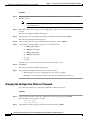
Changing the Configuration Software Password
You can use the serial port to change the configuration software password.
Procedure
Step 1
At the prompt, enter P to change the configuration software password and press Enter.
The user profile screen appears as follows:
Enter user name:
Enter new password:
Step 2
At the Enter user name prompt, enter the new user name and press Enter.
Installation and Upgrade Guide for Cisco Unified Videoconferencing 3515 MCU12 and MCU24 Release 5.1
2-10
OL-11897-01
Chapter 2
Setting Up Your Cisco Unified Videoconferencing 3515 MCU
Video Processing Module Initial Configuration for the 3515 MCU
Step 3
At the Enter user password prompt, enter the new password and press any key to return to the video
processing module Main menu.
Changing the Security Level
You can use the serial port to change the security level. Security levels are as follows:
•
0 (low)—Allows SNMP, Telnet, HTTP, FTP, and ICMP to access the MCU.
•
1 (medium)—Allows access to the MCU only through SNMP, HTTP and ICMP.
•
2 (high)—Allows only HTTP to access the MCU.
Procedure
Step 1
At the prompt, enter S to configure the network security level and press Enter.
The security level screen appears as follows:
The current security level is [0 low].
Enter a new security level (0-low, 1-medium. 2-high):
Step 2
Enter the new security level required and press Enter.
The updated security level screen appears as follows:
The current security level is [0 low].
Enter a new security level (0-low, 1-medium. 2-high):
2
Board security level changing to [2 high]:
Set icmpRequestBlock to 2
The new security level is [2 high].
Step 3
The video processing module Main menu displays.
Pointing the EMP to the Controlling Cisco Unified
Videoconferencing 3515 MCU
You can use the serial port to point the EMP to the IP address of the controlling Cisco Unified
Videoconferencing 3515 MCU unit.
Procedure
Step 1
At the prompt, enter M to change the Cisco Unified Videoconferencing 3515 MCU IP address and press
Enter.
The Cisco Unified Videoconferencing 3515 MCU IP address screen displays as follows:
Enter MCU ip address
Without leading zeros <current IP address>:
Step 2
Enter the IP address of the Cisco Unified Videoconferencing 3515 MCU and press any key to return to
the EMP Main menu.
Installation and Upgrade Guide for Cisco Unified Videoconferencing 3515 MCU12 and MCU24 Release 5.1
OL-11897-01
2-11
Chapter 2
Setting Up Your Cisco Unified Videoconferencing 3515 MCU
Video Processing Module Initial Configuration for the 3515 MCU
Changing Advanced Configuration Settings
You can use the serial port to change the following advanced configuration settings:
•
Web server port (for future use)
•
Restore factory configuration (for future use)
•
LAN port settings
•
Disable DSP reset
Procedure
Step 1
At the prompt, enter A to access the Advanced Configuration menu.
The Advanced Configuration menu appears as follows:
Advanced configuration menu
Q: Quit
1: Configure web server port
2: Restore factory configuration
3: Change Lan port Settings
4: Disable DSP reset
Select:
Step 2
At the prompt, enter 1 to configure the web server port.
The current web port server setting displays.
Step 3
At the prompt, enter 2 to restore the factory configuration settings.
You are asked to confirm your choice as follows:
Select: 2
Are you sure you want to restore factory configuration? [y, n]:
Step 4
Enter y or n.
Step 5
At the prompt, enter 3 to change Ethernet speed and duplex parameters.
The network interface card settings screen appears as follows:
Choose : 1
: 2
: 3
: 4
: 5
other
:
-
10Mbps
100Mbps
10Mbps
100Mbps
Auto
Quit
Half
Half
Full
Full
Duplex
Duplex
Duplex
Duplex
Step 6
Enter either a number between 0 and 5 inclusive, representing the required option.
Step 7
Press any other key to quit without changing the network working mode.
Step 8
At the prompt, enter 4 to disable the DSP reset facility.
Note
Caution
After options Q and 1-3, press any key to return to the video processing module Main menu. After option
4, the video processing module Main menu displays automatically.
Only qualified technical personnel should modify the DSP reset function settings.
Installation and Upgrade Guide for Cisco Unified Videoconferencing 3515 MCU12 and MCU24 Release 5.1
2-12
OL-11897-01
Chapter 2
Setting Up Your Cisco Unified Videoconferencing 3515 MCU
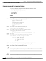
Managing and Monitoring the Cisco Unified Videoconferencing 3515 MCU Unit
Saving Network Configuration Settings
Modified network configuration settings are automatically saved when you exit the video processing
module Main menu.
Procedure
Step 1
Ensure you have completed your configuration.
Step 2
At the prompt, enter Q to exit the video processing module Main menu.
The video processing module Main menu closes and your machine will automatically reboot.
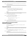
Managing and Monitoring the Cisco Unified
Videoconferencing 3515 MCU Unit
You can manage and monitor the Cisco Unified Videoconferencing 3515 MCU unit locally or from
remote connections. You can also upgrade Cisco Unified Videoconferencing 3515 MCU software.
SNMP Management
The Cisco Unified Videoconferencing 3515 MCU unit is equipped with an SNMP agent. You can access
the Cisco Unified Videoconferencing 3515 MCU unit using an SNMP management client.
Local Port Monitoring Connections
You should access the Cisco Unified Videoconferencing 3515 MCU unit using a local port connection
for preliminary configuration and monitoring.
Serial Port
The Cisco Unified Videoconferencing 3515 MCU unit includes a DB-9 serial port connector and an
RJ-45 serial port connector. The DB-9 serial port is used to access the boot sequence menu from a local
PC. Using a terminal emulation application running on the PC, you can assign an IP address and subnet
mask to the Cisco Unified Videoconferencing 3515 MCU unit.
The RJ-45 serial port is used to connect a PC terminal to the Cisco Unified
Videoconferencing 3515 MCU unit.
Installation and Upgrade Guide for Cisco Unified Videoconferencing 3515 MCU12 and MCU24 Release 5.1
OL-11897-01
2-13
Chapter 2
Accessing the Cisco Unified Videoconferencing 3515 MCU Administrator Interface
Setting Up Your Cisco Unified Videoconferencing 3515 MCU
Performing Software Upgrades
You can perform software upgrades by using the Cisco Upgrade Utility to upload files via a network or
modem connection to the Cisco Unified Videoconferencing 3515 MCU unit. For more information, see
Chapter 3, “Using the Cisco Software Upgrade Utility”.
Accessing the Cisco Unified Videoconferencing 3515 MCU
Administrator Interface
The Cisco Unified Videoconferencing 3515 MCU Administrator is a web interface that allows you to
configure general Cisco Unified Videoconferencing 3515 MCU unit settings, monitor Cisco Unified
Videoconferencing 3515 MCU unit operation, create or edit services, manage media processor units and
perform maintenance.
You access the Cisco Unified Videoconferencing 3515 MCU Administrator web interface in the
Cisco Unified Videoconferencing 3515 MCU unit access window by signing in as an Administrator.
You can use your web browser from any remote PC station to monitor and to configure the Cisco Unified
Videoconferencing 3515 MCU unit. A web server is installed in the Cisco Unified
Videoconferencing 3515 MCU unit to facilitate the use of the remote web-based monitoring and
management.
Access to the Cisco Unified Videoconferencing 3515 MCU configuration interface is controlled by a
user name and a password. Once you have entered the settings you want, you should upload them to the
unit for them to take effect, or you can save them to a configuration file to be loaded at a later time.
Before You Begin
The following requirements are necessary to access the Cisco Unified Videoconferencing 3515 MCU
Administrator web interface:
Note
•
A Java-compliant browser. Microsoft Internet Explorer version 5.5 or later is recommended.
•
The Cisco Unified Videoconferencing 3515 MCU unit IP address or a web link to the Cisco Unified
Videoconferencing 3515 MCU unit.
•
The required user name and password.
For first-time installation, you must assign an IP address to the Cisco Unified
Videoconferencing 3515 MCU unit using a serial port connection before you can access the web
interface. For more information, see the “Setting the IP Address” section on page 2-6.
Procedure
Step 1
Launch your browser and enter the IP address or the name of the Cisco Unified
Videoconferencing 3515 MCU unit followed by /admin.
For example, http://125.221.23.44/admin or board_name/admin.
The Cisco Unified Videoconferencing 3515 MCU access window appears.
Step 2
Enter the Administrator user name and password in the appropriate fields and click Go. The default
global user name is admin. The default password is <null>.
The Cisco Unified Videoconferencing 3515 MCU Administrator interface appears.
Installation and Upgrade Guide for Cisco Unified Videoconferencing 3515 MCU12 and MCU24 Release 5.1
2-14
OL-11897-01
Chapter 2
Setting Up Your Cisco Unified Videoconferencing 3515 MCU
Registering the Online Help for the 3515 MCU
Note
If you try to sign in as an Administrator and another Administrator is currently signed in, the
Cisco Unified Videoconferencing 3515 MCU signs you in as a Read only user. The words Read Only
appear at the top of the window and a pop-up displays the IP address of the Administrator already signed
in. Read only users cannot edit any of the Cisco Unified Videoconferencing 3515 MCU settings.
Registering the Online Help for the 3515 MCU
The online help files for the Cisco Unified Videoconferencing 3515 MCU Administrator and
Conference Control interfaces are shipped on the Cisco Unified Videoconferencing Software CD-ROM.
To use the online help, you must install the help files for the appropriate Cisco Unified
Videoconferencing 3515 MCU in a shared directory on your network and register the directory location
in the Administrator interface.
If you wish to install the online help on a shared network location and link it to the Cisco Unified
Videoconferencing 3515 MCU Administrator, perform the following steps:
Procedure
Step 1
Copy the online help library from the Cisco Unified Videoconferencing Software CD-ROM to a shared
folder on a PC on your network.
Step 2
Log in to the Cisco Unified Videoconferencing 3515 MCU Administrator interface.
Step 3
In the Online help URL field of the Device Web tab, enter the directory path to the help files you installed
on your PC.
The path must have the form:
file://computerName/sharedDirectory
where computerName is the name of the computer on the network and sharedDirectory is the path to the
Online Help folder on the CD-ROM. For example:
file://myComputer/Shared/Online Help
Step 4
Click Upload in the Cisco Unified Videoconferencing 3515 MCU Administrator toolbar, followed by
Refresh.
Step 5
You may need to log out and log back in to the Cisco Unified Videoconferencing 3515 MCU
Administrator for the change to take effect.
Netscape Navigator Users
Online help files located on the local network and accessed using Netscape Navigator 4.x must be
located on a mapped network drive.
Installation and Upgrade Guide for Cisco Unified Videoconferencing 3515 MCU12 and MCU24 Release 5.1
OL-11897-01
2-15
Chapter 2
Setting Up Your Cisco Unified Videoconferencing 3515 MCU
Registering the Online Help for the 3515 MCU
Installation and Upgrade Guide for Cisco Unified Videoconferencing 3515 MCU12 and MCU24 Release 5.1
2-16
OL-11897-01
C H A P T E R
3
Using the Cisco Software Upgrade Utility
This section describes the following topics:
•
Introduction, page 3-1
•
Launching the Cisco Software Upgrade Utility, page 3-1
•
Upgrading Software, page 3-2
Introduction
The Cisco Software Upgrade Utility is an interactive GUI interface that enables you to upgrade Cisco
software installed on Cisco devices.
The Cisco Software Upgrade Utility enables you to select files to be uploaded via a network or modem
connection to the Cisco device. You can select either to perform a typical upgrade which includes all the
new files or a customized upgrade which enables you to select which files to upload.
The upgrade files are uploaded and then burned into the memory of the Cisco device.
Before You Begin
Cisco devices automatically save configuration settings before a software upgrade takes place. However,
it is recommended that you save all configuration information using the Export button in the Cisco
device web interface toolbar. You can retrieve all these settings after the software upgrade is complete
by using the Import button in the Cisco device web interface toolbar.
Launching the Cisco Software Upgrade Utility
This section describes how to install and launch the Cisco Software Upgrade Utility.
Procedure
Step 1
Download the UpgradeUtility.exe file from the Cisco Unified Videoconferencing Software CD-ROM.
Step 2
Double click the UpgradeUtility.exe file to run the Software Upgrade Utility.
The upgrade files are extracted and the Upgrade Utility dialog box appears.
Installation and Upgrade Guide for Cisco Unified Videoconferencing 3515 MCU12 and MCU24 Release 5.1
OL-11897-01
3-1
Chapter 3
Using the Cisco Software Upgrade Utility
Upgrading Software
Upgrading Software
This section describes how to use the Software Upgrade Utility to upgrade Cisco software installed on
Cisco devices.
Procedure
Step 1
In the General Information section of the Upgrade Utility dialog box, enter the IP address of the device
you want to upgrade.
Step 2
In the Login Information section, enter the administrator user name and password for the target device,
as configured in the device network configuration settings.
Step 3
(Optional) Modify the read and write community settings for the target device as follows:
– Click Customize SNMP Settings.
The Customize SNMP Settings dialog box displays.
– Enter the required read community and write community values.
Note
We recommend that you modify the default settings for security purposes.
– Click OK to return to the Upgrade Utility dialog box.
Step 4
(Optional) Select the components of the target device you want to upgrade as follows:
– Click Customize.
The Customize dialog box appears.
– Check the device components you want to upgrade in the Select the components you want to
upgrade list.
Note
The components displayed vary according to the Cisco device upgraded.
– Click OK to return to the Upgrade Utility dialog box.
Step 5
Click Upgrade to upgrade all components of the Cisco device software (or only those components you
manually selected via the Customize option).
The Cisco Software Upgrade Utility informs you whether or not the upgrade is successful.
Note
When the upgrade is complete, the Cisco device automatically resets itself and starts
operation with the new software version.
Installation and Upgrade Guide for Cisco Unified Videoconferencing 3515 MCU12 and MCU24 Release 5.1
3-2
OL-11897-01
C H A P T E R
4
Cisco Unified Videoconferencing 3515 MCU
Cable Connections and Pin-outs
This section describes the following topics:
•
Unit RS-232 9-Pin Serial Port on the 3515 MCU, page 4-1
•
RJ-45 8-Pin IP Network Port on the 3515 MCU, page 4-2
Unit RS-232 9-Pin Serial Port on the 3515 MCU
Table 4-1 describes the Cisco Unified Videoconferencing 3515 MCU unit RS-232 9-pin D-type serial
port pin-out configuration.
Table 4-1
RS-232 9-pin D-Type Serial Port Pin-out
Pin
Function
I/O
1
NC
2
RXD
Input
3
TXD
Output
4
NC
5
GND
6
NC
7
NC
8
NC
9
NC
Installation and Upgrade Guide for Cisco Unified Videoconferencing 3515 MCU12 and MCU24 Release 5.1
OL-11897-01
4-1
Chapter 4
Cisco Unified Videoconferencing 3515 MCU Cable Connections and Pin-outs
RJ-45 8-Pin IP Network Port on the 3515 MCU
RJ-45 8-Pin IP Network Port on the 3515 MCU
Table 4-2 describes the pin-out configuration of the RJ-45 IP network port.
Table 4-2
Pin-out Configuration of the RJ-45 IP Network Port
Pin
Function
I/O
1
TXD+
Output
2
TXD+
Output
3
RXD+
Input
4
NC
5
NC
6
RXD-
7
NC
8
NC
Input
Installation and Upgrade Guide for Cisco Unified Videoconferencing 3515 MCU12 and MCU24 Release 5.1
4-2
OL-11897-01
C H A P T E R
5
Cisco Unified Videoconferencing 3515 MCU
Technical Specifications
This section provides technical specifications for the Cisco Unified Videoconferencing 3515 MCU.
Technical Specifications Table for the 3515 MCU
Table 5-1
Unit Dimensions
LED Indicators
Cisco Unified Videoconferencing 3515 MCU Unit Technical Specifications
•
Height: 1U (1.75 inches or 44.45 mm)
•
Width: 17.25 inches (438.15 mm)
•
Depth: 10 inches (254 mm)
•
Weight: 4.45 kg (9.81 lbs)—may vary according to configuration
•
10/100 BaseT:
– Link
– Connection Speed
•
GK Reg
•
CPU High
•
ALARM
•
ACT
•
MC (video processing module only)
Push Buttons
•
RST
Communication
Interfaces
•
Ethernet 10/100 Mbps auto-negotiate speed select
•
Asynchronous serial port RS-232 connected via 9-pin D-type connector
•
RJ-45 serial port (for video processing module)
•
SVGA port (for video processing module)
•
USB connector (for video processing module)
•
PowerPC MPC755 32-bit RISC microprocessor running at 400MHz or
more
•
MPC8260 secondary microprocessor running at 200/133MHz or more
Chipset
Installation and Upgrade Guide for Cisco Unified Videoconferencing 3515 MCU12 and MCU24 Release 5.1
OL-11897-01
5-1
Chapter 5
Cisco Unified Videoconferencing 3515 MCU Technical Specifications
Technical Specifications Table for the 3515 MCU
Table 5-1
Cisco Unified Videoconferencing 3515 MCU Unit Technical Specifications (continued)
Operating System
•
RTOS, VxWorks 5.4
Memory
•
32 MB on-board flash memory for field upgrades, supports up to 64 MB
•
1 MB L-2 Cache at 200 MHz or more
•
128 MB SDRAM, supports up to 256 MB
Failsafe
•
Watchdog timer built in
Power Supply
•
Input 100-240VAC autoswitched
•
Output + 3.3VDC, + 5VDC, + 12VDC
•
Maximum power load 150W
Installation and Upgrade Guide for Cisco Unified Videoconferencing 3515 MCU12 and MCU24 Release 5.1
5-2
OL-11897-01
C H A P T E R
6
Cisco Unified Videoconferencing 3515 MCU
Safety
This section describes the following topics:
•
Electrical Safety for the 3515 MCU, page 6-1
•
ESD Procedures for the 3515 MCU, page 6-2
Electrical Safety for the 3515 MCU
To avoid an electric shock or damage to the Cisco Unified Videoconferencing 3515 MCU unit, servicing
should be performed by qualified service personnel only.
To reduce the risk of damaging power surges, Cisco recommends installing an AC surge arrestor in the
AC outlet from which the Cisco Unified Videoconferencing 3515 MCU unit is powered.
Warning
Do not attempt to open the Cisco Unified Videoconferencing 3515 MCU unit.
Warning
Changes or modifications to the device that are not approved by the party responsible for compliance
could void the user’s authority to operate the equipment.
Grounding
The power cable of the Cisco Unified Videoconferencing 3515 MCU unit should only be connected to a
power outlet that has a protective earth contact. Do not use an extension cord that does not have a
protective conductor (ground). The Cisco Unified Videoconferencing 3515 MCU unit can become
dangerous if you interrupt any of the protective conductors (grounding) or disconnect any of the
protective earth terminals.
Installation and Upgrade Guide for Cisco Unified Videoconferencing 3515 MCU12 and MCU24 Release 5.1
OL-11897-01
6-1
Chapter 6
Cisco Unified Videoconferencing 3515 MCU Safety
ESD Procedures for the 3515 MCU
High Voltage
Disconnect the Cisco Unified Videoconferencing 3515 MCU unit from the power line before removing
the cover. Avoid any adjustment, maintenance, or repair of an opened chassis under voltage. These
actions should only be carried out by a skilled person who is aware of the dangers involved. Capacitors
inside the chassis may still be charged, even if the unit has been disconnected from the power source.
ESD Procedures for the 3515 MCU
To prevent damage to the Cisco Unified Videoconferencing 3515 MCU unit by random electrostatic
discharge (ESD), the use of wrist straps is highly recommended.
Installation and Upgrade Guide for Cisco Unified Videoconferencing 3515 MCU12 and MCU24 Release 5.1
6-2
OL-11897-01
C H A P T E R
7
Cisco Unified Videoconferencing 3515 MCU
Compliance and Certifications
This section describes the following topics:
•
Safety Compliance for the 3515 MCU, page 7-1
•
EMC for the 3515 MCU, page 7-1
•
Telecom for the 3515 MCU, page 7-2
•
Environmental Compliance for the 3515 MCU, page 7-4
Safety Compliance for the 3515 MCU
This section lists the safety standards supported by the Cisco Unified Videoconferencing 3515 MCU
unit.
•
UL 60950
•
CSA C22.2 No. 60950
•
EN 60950
•
TS 001
•
AS/NZS 60950
•
IEC 60950
EMC for the 3515 MCU
This section lists the EMC compliance for the Cisco Unified Videoconferencing 3515 MCU unit.
•
FCC Part 15 (CFR 47) Class A
•
ICES-003 Class A
•
EN 55022 Class A
•
CISPR22 Class A
•
AS/NZS CISPR22 Class A
•
VCCI Class A
•
CISPR24
Installation and Upgrade Guide for Cisco Unified Videoconferencing 3515 MCU12 and MCU24 Release 5.1
OL-11897-01
7-1
Chapter 7
Cisco Unified Videoconferencing 3515 MCU Compliance and Certifications
Telecom for the 3515 MCU
Warning
•
EN 55024
•
EN 50082-1
•
EN 61000-3-2
•
EN 61000-3-3
•
EN 61000-6-1
This is a class A product. In a domestic environment this product may cause radio interference in
which case the user may be required to take adequate measures.
FCC Part 15 Notice
This section provides RF interference information for the user.
This equipment has been tested and found to comply with the limits for a Class A digital device, pursuant
to Part 15 of the FCC rules. These limits are designed to provide reasonable protection against harmful
interference when the equipment is operated in a commercial environment. This equipment generates,
uses, and can radiate radio frequency energy and, if not installed and used in accordance with the
instruction manual, may cause harmful interference to radio communications. Operation of this
equipment in a residential area is likely to cause harmful interference, in which case the user will be
required to correct the interference at one’s own expense.
Warning
Changes or modifications to the device that are not approved by the party responsible for compliance
could void the user’s authority to operate the equipment.
Telecom for the 3515 MCU
•
This section lists standards compliance for products that connect to ISDN lines.
•
ACTA Part 68
•
Industry Canada
•
CE CTR3, CE CTR4
ACTA Part 68 Notice
Step 1
This equipment complies with ACTA Part 68. On the cover of this equipment is a label that contains,
among other information, the ACTA registration number. If requested, this information must be provided
to the telephone company.
Step 2
Applicable registration jack USOCs (Universal Service Order Codes) for the equipment is RJ48C for
PRI interfaces and RJ49C for BRI interfaces.
Step 3
An FCC compliant telephone cord and modular plug is provided with equipment. This equipment is
designated to be connected to the telephone network or premises wiring using a compatible modular jack
which is Part 68 compliant. See Installation Instructions for details.
Installation and Upgrade Guide for Cisco Unified Videoconferencing 3515 MCU12 and MCU24 Release 5.1
7-2
OL-11897-01
Chapter 7
Cisco Unified Videoconferencing 3515 MCU Compliance and Certifications
Telecom for the 3515 MCU
Step 4
If the terminal equipment Cisco Unified Videoconferencing 3515 MCU causes harm to the telephone
network, the telephone company will notify you in advance that temporary discontinuance of service
may be required. But if advance notice is not practical, the telephone company will notify the customer
as soon as possible. Also, you will be advised of your right to file a complaint with the FCC if you believe
it is necessary.
Step 5
The telephone company may make changes in its facilities, equipment, operations or procedures that
could affect the operation of the equipment. If this happens, the telephone company will provide advance
notice in order for you to make necessary modifications to maintain uninterrupted service.
Step 6
If trouble is experienced with the Cisco Unified Videoconferencing 3515 MCU equipment, please
contact your Cisco representative for information on service or repairs. If the equipment is causing harm
to the telephone network, the telephone company may request that you disconnect the equipment until
the problem is resolved.
Step 7
The Facility Interface Codes are: 04DU9-BN; 04DU9-DN; 04DU9-1SN. The Service Order Code is:
6.0N.
Step 8
Only Cisco Systems, Inc. qualified service personnel may repair the equipment.
Industry Canada
The Industry Canada (IC) label identifies certified equipment. This certification means that the
equipment meets certain telecommunications network protective, operational and safety requirements.
The IC does not guarantee the equipment will operate to the user's satisfaction.
Before installing this equipment, users should ensure that it is permissible to be connected to the
facilities of the local telecommunications company. The equipment must also be installed using an
acceptable method of connection. In some cases, the company's inside wiring associated with a single
line individual service may be extended by means of a certified connector assembly (telephone extension
cord). The customer should be aware that compliance with the above condition may not prevent
degradation of service in some situations.
Repairs to some certified equipment should be made by an authorized maintenance facility designated
by the supplier. Any repairs or alterations made by the user to this equipment, or equipment
malfunctions, may give the telecommunications company cause to request the user to disconnect the
equipment.
Users should ensure for their own protection that the ground connections of the power utility, telephone
lines and internal metallic water pipe system, are connected together. This precaution may be
particularly important in rural areas.
The abbreviation, IC, before the registration number signifies that registration was performed based on
a Declaration of Conformity indicating that Industry Canada technical specifications were met. It does
not imply that Industry Canada approved the equipment.
Warning
Users should not attempt to make such connections themselves, but should contact the appropriate
electric inspection authority, or electrician, as appropriate.
Installation and Upgrade Guide for Cisco Unified Videoconferencing 3515 MCU12 and MCU24 Release 5.1
OL-11897-01
7-3
Chapter 7
Cisco Unified Videoconferencing 3515 MCU Compliance and Certifications
Environmental Compliance for the 3515 MCU
Environmental Compliance for the 3515 MCU
Cisco complies with the following EU Directives:
•
Restrictions on the Use of Hazardous Substances (RoHS) Directive 2002/95/EC
•
Waste Electrical and Electronic Equipment (WEEE) Directive 2002/96/EC
Installation and Upgrade Guide for Cisco Unified Videoconferencing 3515 MCU12 and MCU24 Release 5.1
7-4
OL-11897-01
INDEX
video
Numerics
1-4
communication interfaces
5-1
19-inch rack
2-4
communication settings
mount unit
2-4
Conference Control interface
6-second countdown
9-pin serial-port
2-5, 2-7
Configuration menu
2-1
D
ACT LED See LED indicators
data collaboration
Administrator interface
DB-9
1-2, 2-14
Advanced Configuration menu
architecture
2-8, 2-10, 2-12
1-6
DTMF
1-3
auto-boot
1-4
1-4
Duo Video
codecs
1-4
2-2, 2-13
dual-screen video
audio
1-2
2-5
Continuous Presence
A
2-6
1-4
1-4
duplex parameters
2-9, 2-12
2-5
E
B
EMC
boot configuration menu
2-5
7-1
encryption
1-4
Ethernet
cable
C
port
speed
cables
RJ-45 8-pin IP network port
RS-232 9-pin serial port
cascaded conferences
1-7
Certifications
EMC
Telecom
chipset
2-1
2-9, 2-12
4-2
4-1
F
failsafe
7-1
2-3
5-2
flat capacity
7-2
front panel
5-1
1-2
2-2
components
2-2
codecs
audio transcoding
1-3
Installation and Upgrade Guide for Cisco Unified Videoconferencing 3515 MCU12 and MCU24 Release 5.1
OL-11897-01
IN-1
Index
save network configuration settings
G
set default network properties
GK LED See LED indicators
set duplex parameters
global user name
set Ethernet speed
2-14
interoperability
2-9
2-10, 2-12
2-10, 2-12
installation requirements
H
2-13
2-2
1-3
IP address
H.235
1-3
change for unit
H.239
1-3, 1-4
configure for unit
H.243
1-4
configure for video processing module
High Definition
IVR
1-5
2-11
2-6
2-9
1-4
L
I
initial configuration
initialization
LAN cable
2-5
layouts
2-5
Continuous Presence
installation procedures
access administrator interface
LED indicators
2-14
change advanced configuration settings
change password
M
2-12
2-7
change security level
Main menu
2-11
change unit IP address
2-11
configure IP address for unit
memory
2-7, 2-8
configure network security level
2-7, 2-8
2-12
multi-view See dual-screen video
2-9
N
Netscape Navigator
2-12
connect to the serial port
2-5
connect unit to the LAN
2-8
disable DSP reset
5-2
2-6
configure IP address for video processing module
configure web server port
2-8, 2-11, 2-12
MC LED See LED indicators
configure default network port values
configure web server
2-15
Network Configuration menu
2-7, 2-8, 2-10
O
2-12
display Advanced Configuration menu
display advanced configuration menu
2-8
2-7
online help
2-15
Netscape Navigator
mount unit in a 19-inch rack
2-4
operating system
restore factory configuration
2-12
optional no self see
restore factory settings
2-13
2-8, 2-10
2-8
change LAN port settings
1-4
2-2, 5-1
local port monitoring
2-12
change configuration software password
change IP address
2-3
2-15
5-2
1-4
2-12
Installation and Upgrade Guide for Cisco Unified Videoconferencing 3515 MCU12 and MCU24 Release 5.1
IN-2
OL-11897-01
Index
software upgrade utility procedures
P
install and launch
package contents
2-3
use utility
password
3-2
summary of features
change configuration software password
pin-out configuration
RJ-45 IP network port
4-1
ports
2-10
T.120
1-4
Telecom
RJ-45 IP
4-2
power supply
7-2
terminal cable
RS-232 9-pin serial
4-1
topologies
5-2
2-5
1-7
transcoding
1-3
1-4
protocols
1-3
push buttons
U
5-1
unit dimensions
5-1
upgrade software
R
user types
remote control
1-4
reset button
2-2
1-2
chair controllers
1-2
conference participants
2-2
operators
RS-232 terminal cable
RST
2-13
3-1
1-2
administrators
remote management and monitoring
RJ-45
1-2
T
4-2
RS-232 9-pin D-type serial port
privacy
3-1
1-2
1-2
2-5
2-2
RST button
V
5-1
video
codec
S
coding
Safety
formats
compliance
electrical
7-1
1-4
video quality
1-2, 1-4
6-2
W
1-4
change security level
self-view
1-4
6-1
ESD procedures
security
1-4
2-11
web-based management and control
1-4
serial connector
web interface
1-3
2-14
2-2
SNMP
agent
2-13
Software Upgrade Utility
2-14
Installation and Upgrade Guide for Cisco Unified Videoconferencing 3515 MCU12 and MCU24 Release 5.1
OL-11897-01
IN-3
Index
Installation and Upgrade Guide for Cisco Unified Videoconferencing 3515 MCU12 and MCU24 Release 5.1
IN-4
OL-11897-01