1
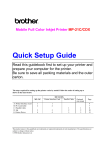
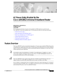
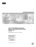
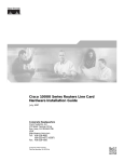
Quick Start Guide
1 Description
Saving to a Media Card
The Cisco Performance Routing Engine
(ESR-PRE2) is a single-slot module that performs
Layer 2 and Layer 3 packet routing and
forwarding using Parallel eXpress Forwarding
(PXF).
Step 1
Connect the console to the primary PRE or
PRE1.
Step 2
2 Upgrading to a PRE2
This upgrade should be performed by a qualified
engineer who is familiar with the Cisco router
console interface.
Step 4
Unscrew the captive screws.
Step 5
Simultaneously pivot both ejector levers
away from each other to disengage the
module from the backplane.
Copy the startup configuration and
running configuration to the existing
removable media card.
Step 6
Slide the PRE/PRE1 out of the slot and
place it on an anti-static surface or in an
anti-static bag.
Step 3
Download the full PRE2 image from the
TFTP server to the media card.
Step 7
If you are replacing a redundant
PRE/PRE1, repeat Step 3 through Step 6.
Step 4
If you have a redundant PRE or PRE1,
save this information on the redundant
PRE or PRE1 media card.
Step 5
Remove the media cards from the modules
and set them aside.
Upgrade Considerations
• This is a service-impacting hardware upgrade.
The router will not be available for user traffic
during the upgrade, and traffic cannot resume
until the upgrade is complete.
Cisco Performance Routing
Engine (ESR-PRE2) Upgrade
Installation
1
Description
2
Upgrading to a PRE2
3
Troubleshooting
4
Technical Specifications
5
Related Documentation
Warning
Caution
Only trained and qualified
personnel should be allowed to
install, replace, or service this
equipment. Statement 1030
Always wear a grounding wrist
strap to avoid ESD damage to the
module.
• PREs or PRE1s cannot operate with a PRE2 in
the same chassis and should never be installed
in a chassis together.
• PRE2 modules to be installed must have the
helper image (eboot) stored in the onboard
boot flash, no configuration, and must be set
to boot into ROMMON. Individual PRE2
modules ship in this state.
• The new PRE2 image must exist on the TFTP
server.
Note
Saving to the TFTP Server
Step 1
Connect to the primary PRE or PRE1
console.
Step 2
Save the startup configuration and
running configuration to the TFTP server.
Removing the PRE or PRE1 Module
Note
Saving the Startup and Running
Configuration Information
When the PRE or PRE1 is removed from the
chassis, any local configuration is lost. You must
save your configuration information to the TFTP
server or media card before removing the module.
If you plan to use the media card from your current
PRE or PRE1, you can save your startup
configuration, running configuration, and the
latest PRE2 image (from the TFTP server) to the
media card.
Installing a PRE2 Module
Warning
Modules can be hot-swapped. However,
removing a module terminates all traffic.
We recommend that you power down the
router to ensure a successful installation.
Hazardous voltage or energy is
present on the backplane when the
system is operating. Use caution
when servicing. Statement 1034
Step 1
Ensure that you are properly grounded.
Step 2
Power down the router
Step 3
Disconnect the cables from the PRE/PRE1.
To ensure proper operation, always install
a single PRE2 in slot A. If you are
installing a redundant PRE2 in slot B, wait
until after you have installed and
configured the primary PRE2 in slot A.
Equipment
ESD wrist strap
Replacement PRE2 modules
Step 1
Ensure that you are properly grounded.
Step 2
Inspect the connectors on both the PRE2
and the backplane. Bent or broken pins
can cause a system malfunction.
Step 3
Carefully align the PRE2 module with the
guides in slot A in the chassis.
Step 4
Slide the module into the slot until you can
feel it seat in the backplane.
Corporate Headquarters
Cisco Systems, Inc.
170 West Tasman Drive
San Jose, CA 95134-1706
USA
http://www.cisco.com
Tel: 408 526-4000
800 553-NETS (6387)
Fax: 408 526-4100
Copyright © 2004 Cisco Systems, Inc. All rights reserved. Cisco, Cisco IOS, Cisco Systems, and
the Cisco Systems logo are registered trademarks of Cisco Systems, Inc. or its affiliates in the
United States and certain other countries. All other brands, names, or trademarks mentioned in
this document or Website are the property of their respective owners. The use of the word partner
does not imply a partnership relationship between Cisco and any other company. (0401R)
Printed in the USA on recycled paper
containing 10% postconsumer waste.
78-16710-01
Figure 1
Step 10 Boot the full image (if available) from the
media card or from the TFTP server.
Cisco uBR10012 Router
CISCO
CISCO
10000
10000
CISCO
10000
CO
CONS
NSOLE
OL
E
CO
NS
POWER
MISWIR
E
FAULT
POWER
MISWIR
E
FAULT
AUX
OL
E
AU
X
AU
X
If the full image is not available, boot the
helper image from the onboard boot flash.
After booting the router prompts for an
initial configuration dialog.
AC
TIV
AC ITY
ETHTIV
AC
ITY
ET
LIN
ERITY
NE
HE
K
T
LIN RN
K ET
1
ER
SLOT
0
SLOT
TIV
ETH
LIN
NE
K
T
Step 11 If you need to access the TFTP server to
obtain the full image or the saved
configuration files, enter the configuration
dialog and provide the information
necessary to access the TFTP server.
ALARMS
ALARMS
CR
ITIC
CR
ITIC
MA
AL
JOR
MIN
MA
AL
JOR
MIN
OR
OR
AC
O
AC
O
T
SLO
T
SLO
STA
TU
FAI S
L
1
0
STA
TUS
FAI
L
1
0
ALARMS
AC
O
CR
ITIC
AL
MA
R
OR
If you booted the full image, restore the
startup configuration and running
configuration information, and set the
boot variable for the new image. The
upgrade is now complete.
122201
PERFORMANCE ROUTING ENGINE ESR-PRE2
PERFORMANCE ROUTING ENGINE ESR-PRE2
STA
TU
FAI S
L
PERFORMANCE ROUTING ENGINE
PERFORMANCE ROUTING ENGINE
JO
MIN
Figure 2
Cisco ESR10000 Router
FANS
OK
FAN
FAILURE
If you booted from the helper image,
download the full image, restore the
startup and running configuration
information, set the boot variable to the
new image, and reload the router. The
upgrade is now complete.
MULTIFAN
FAILURE
When hot CAUTION
remova swapping
be donel and replacethis fan tray,
system in under twoment must
shutdow
minutes
n will occur. or
1
2
CISCO
10000
3
CISCO
10000
4
0A
PROCES
SOR ONL0B
Y
5
6
CISCO
10000
L
FAI
FAI
CISCO
10000
7
L
FAI
L
FAI
L
8
CISCO
10000
CISCO
10000
CISCO
10000
CISCO
10000
FAI
CISCO
10000
L
FAI
L
FAI
L
CISCO
10000
FAI
CO
L
NS
CA
OL
OP
LO
RM
ALA
IER
RR
CA
OP
LO
RM
ALA
IER
RR
E
0
CO
NS
AU
X
0
OL
CA
E
OP
LO
RM
ALA
IER
0
0
If this sequence does not occur, the STATUS LED is
off, or the FAIL LED is yellow, check the following:
1. Are the LEDs on other modules on? If not,
check for a problem in the power subsystem.
2. If other module’s LEDs are on, remove the
PRE2 from the slot, check for bent or broken
pins on the connectors, and reinsert it. Ensure
that there is solid contact with the backplane
and that the PRE2 is securely locked in place.
3. Verify the status of the PRE2 module’s internal
Ethernet interface (ethernet0/0/0). If this
internal interface is down, it could indicate
that the PRE2 is not fully seated in the slot or
that a hardware failure has occurred. Do not
confuse the PRE2 internal Ethernet interface
(ethernet 0/0/0) with the module’s external
Fast Ethernet interface (fastethernet 0/0/0),
which is used for network management and
remote access.
1
2
1
2
POWER
FAULT
MISWIRE
RR
0
CA
1
OT
0
OT
SL
SL
TIV
ET ITY
HE
LIN RN
ET
K
1
OT
0
OT
1
SL
SL
1
OP
LO
RM
ALA
IER
ET
HE
LIN RN
ET
K
X
AC
RR
ITY
CA
TIV
OP
LO
RM
ALA
IER
RR
AC
AU
4. The redundant PRE2 boot sequence is similar,
except that the STATUS LED remains off and
the final message is IOS STBY, indicating that
the PRE2 is in standby state.
1
2
3
2
2
Table 1
OP
LO
RX
K
RM
ALA
IER
TX
RR
CA
LIN
3
3
4
3
4
3
LED and Switch Descriptions
CA
RX
4
TX
IER
4
5
5
5
Installing a Redundant PRE2
5
IC
AL
JO
R
NO
R
6XCT3–DS0
OC–12/STM–4 POS SM–IR
R
IT
MI
6XCT3–DS0
NO
O
MA
6XCT3–DS0
R
MI
AC
CR
PERFORMANCE ROUTING ENGINE
AL
6XCT3–DS0
IC
JO
PERFORMANCE ROUTING ENGINE
IT
6XCT3–DS0
O
CR
MA
CH OC-12-DSO SM-IR
GIGABIT ETHERNET
AC
POWER
FAULT
MISWIRE
ST
AT
US
FA
IL
ST
AT
US
FA
Step 1
Repeat Step 1 through Step 8 for slot B.
Step 2
From the console ROMMON prompt, set
the configuration to boot the full image
and reload.
IL
PROCES
122202
SOR ONL
Y
Step 5
Simultaneously close the ejector levers to
firmly seat the PRE2 in the backplane.
Step 6
Tighten the captive screws.
3 Troubleshooting
Step 7
Reconnect all the cables to the PRE2 and
connect to the console.
The PRE2 goes through a specific LED sequence at
startup.
If you saved files to the old media card,
replace the new media card with the old
media card.
1. The FAIL LED briefly comes on and then goes
off, and the STATUS LED starts flashing and
progress messages appear on the PRE2 display.
Power on the router. The PRE2 cycles
through its power-on self-test. The FAIL
LED stays on briefly, goes off, and then
boots into ROMMON mode.
2. IOS RUN appears after a successful bootup.
Step 8
Step 9
3. The STATUS LED on the PRE2 turns green.
LED and Switch Descriptions
LEDs/Switch
Description
ACO1 switch
Disables the audible alarm
1. Alarm cutoff switch
4 Technical Specifications
Description
Specification
PRE2
PRE2 spare
ESR-PRE2/R
ESR-PRE2=
Weight
8.45 lb (3.84 kg)
Power consumption per 200 Watts
module
(682.4 btu per hour)
5 Related Documentation
PRE2 installation and upgrade information (uBR):
http://www.cisco.com/univercd/cc/td/doc/product/
cable/ubr10k/ubr10012/frus/ub10pre.htm
Cisco uBR10000 series release notes:
RR
4
5
Table 1
LEDs/Switch
Description
ACTIVITY
Packets are being transmitted
and received
No packet activity
Green/Off
LINK
Green/Off
CRITICAL
MAJOR
MINOR
Green/Off
FAIL
Off/Yellow
Cisco uBR10000 software configuration
information:
Carrier detected; passing traffic
No carrier detected; not passing
traffic
http://www.cisco.com/univercd/cc/td/doc/product/
cable/ubr10k/index.htm.
No alarm
Alarm condition
http://www.cisco.com/univercd/cc/td/doc/product/
cable/ubr10k/ub10rcsi.htm
Regulatory compliance and safety information:
PRE2 installation and upgrade information (ESR):
Off/Yellow
STATUS
http://www.cisco.com/univercd/cc/td/doc/product/
cable/ubr10k/ub10krns/index.htm
PRE2 is ready.
No power to the PRE2, or it is
acting as the redundant PRE2
PRE2 is operating properly
PRE2 disabled by major failure
PCMCIA slot 0
Flash card in Slot 0 is active
PCMCIA slot 1
Flash card in Slot 1 is active
http://www.cisco.com/univercd/cc/td/doc/product/
aggr/10000/8hwdocs/cardinst/prelc.htm
Cisco 10000 router release notes:
http://www.cisco.com/univercd/cc/td/doc/product/
aggr/10000/10krn/index.htm
Cisco 10000 configuration guides:
http://www.cisco.com/univercd/cc/td/doc/product/
aggr/10000/config/index.htm