1
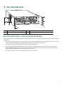
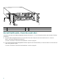
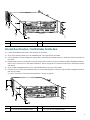
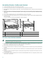
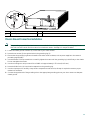
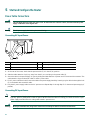
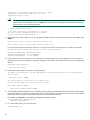
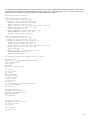
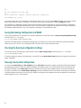
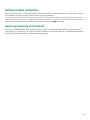
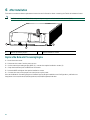
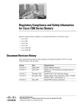
Cisco 7206 Router Quick Start Guide
1
Documentation and Resources
2
Prepare for Installation
3
Rack-Mount the Router
4
Connect the Router to the Network
5
Start and Configure the Router
6
After Installation
7
Technical Assistance
1 Documentation and Resources
This section contains information to help you prepare for installing the Cisco 7206 router. I contains a list of online
documentation and resources.
Document Revision History
The Document Revision History below, records technical changes to this document.
Table 1
Document Revision History
Document Version
Date
Notes
78-12771-04
March, 2006
Adding documentation survey information.
Documentation Survey
Is Cisco documentation helpful? Click here or go to
http://forums.cisco.com/eforum/servlet/viewsflash?cmd=showform&pollid=rtgdoc01!rtgdoc to give us your feedback.
Related Documentation
For detailed hardware installation instructions, refer to the online Cisco 7206 Installation and Configuration Guide
DOC-783229= at http://www.cisco.com/univercd/cc/td/doc/product/core/7206/7206ig/index.htm
Also see the following online and printed documentation:
• Network Processing Engine and Network Services Engine Installation and Configuration—DOC-7810469=
http://www.cisco.com/univercd/cc/td/doc/product/core/7206/fru/npense/index.htm
• Input/Output Controller Replacement Instructions—DOC-783224=
http://www.cisco.com/univercd/cc/td/doc/product/core/7206/fru/3224iofe.htm
• Memory Replacement Instructions for the Network Processing Engine or Network Services Engine and Input/Output
Controller—DOC-783226=
http://www.cisco.com/univercd/cc/td/doc/product/core/7206/fru/memory/index.htm
• Using the Flash Disk—DOC-785819=
http://www.cisco.com/univercd/cc/td/doc/product/core/7200vx/72vxfru/5819fdsk.htm
• 280-Watt AC-Input Power Supply Replacement Instructions—DOC-783227=
http://www.cisco.com/univercd/cc/td/doc/product/core/7206/fru/3227pwr6.htm
• 280-Watt DC-Input Power Supply Replacement Instructions—DOC-783420=
http://www.cisco.com/univercd/cc/td/doc/product/core/7206/fru/3420dcp6.htm
• Rack-Mount and Cable-Management Kit Installation Instructions—DOC-783421=
http://www.cisco.com/univercd/cc/td/doc/product/core/7206/fru/3421rmk6.htm
• Cisco 7200 Rack Density System (RDS) Installation Instructions—DOC-7811310=
http://www.cisco.com/univercd/cc/td/doc/product/core/7200vx/72vxfru/rds11310.htm
• Quick Reference for the Cisco 7206 Installation—DOC-783230=
http://www.cisco.com/univercd/cc/td/doc/product/core/7206/7206qrc/3230qrc6.htm
• Regulatory Compliance and Safety Information for Cisco 7200 Series Routers—DOC-783419=
http://www.cisco.com/univercd/cc/td/doc/product/core/7206/3419pnc6.htm
• Site Preparation and Safety Guide—DOC-786451=
http://www.cisco.com/univercd/cc/td/doc/product/lan/cat5000/hardware/safety/index.htm
2
Port Adapter Documentation
• Cisco 7200 Series Port Adapter Hardware Configuration Guidelines—DOC-783471=
(This document provides bandwidth point information for Cisco 7200 series routers and port adapters.)
http://www.cisco.com/univercd/cc/td/doc/product/core/7206/port_adp/config/index.htm
• Port adapter documentation—See the document that ships with the port adapter for the customer order number. Port
adapter documentation is online at:
http://www.cisco.com/univercd/cc/td/doc/product/core/7206/port_adp/index.htm
• Port adapter cable documentation:
– Installing High-Speed Serial Interface Cables—DOC-784260
http://www.cisco.com/univercd/cc/td/doc/product/access/acs_mod/cis4000/4000cn/4260hcab.htm
– Installing the 75-Ohm In-Line Coaxial Attenuator on Cisco Port Adapters—DOC-7812884
http://www.cisco.com/univercd/cc/td/doc/product/core/7206/fru/12884att.htm
– Installing the 75-120 Ohm Adapter Cable on E1 Multi-Channel Port Adapters—DOC-786728
http://www.cisco.com/univercd/cc/td/doc/product/core/7206/port_adp/multich/6728cabl.htm
Other Useful Links
• For Cisco IOS Configuration documentation including release notes and feature modules, see:
http://www.cisco.com/univercd/cc/td/doc/product/software/index.htm
• Registered Cisco.com users, see the Hardware-Software Compatibility Matrix:
http://www.cisco.com/cgi-bin/front.x/Support/HWSWmatrix/hwswmatrix.cgi
• Registered Cisco Direct users, see the Feature Navigator: http://www.cisco.com/cgi-bin/Support/FeatureNav/FN.pl
• Registered Cisco Direct users, see the Bug Toolkit: http://www.cisco.com/support/bugtools/Bug_root.html
• Registered Cisco Direct users, see the Bug Navigator: http://www.cisco.com/support/bugtools/bugtool.shtml
• Configuration Tool: http://www.cisco.com/pcgi-bin/front.x/newConfig/config_root.pl
Obtaining Documentation
The following sections explain how to obtain documentation from Cisco Systems.
World Wide Web
You can access the most current Cisco documentation on the World Wide Web at the following URL:
http://www.cisco.com
Translated documentation is available at the following URL:
http://www.cisco.com/public/countries_languages.shtml
Documentation CD-ROM
Cisco documentation and additional literature are available in a Cisco Documentation CD-ROM package, which is shipped with
your product. The Documentation CD-ROM is updated monthly and may be more current than printed documentation. The
CD-ROM package is available as a single unit or through an annual subscription.
3
Ordering Documentation
Cisco documentation is available in the following ways:
• Registered Cisco.com users (Cisco direct customers) can order Cisco product documentation from the Networking Products
MarketPlace:
http://www.cisco.com/cgi-bin/order/order_root.pl
• Registered Cisco.com users can order the Documentation CD-ROM through the online Subscription Store:
http://www.cisco.com/go/subscription
• Nonregistered Cisco.com users can order documentation through a local account representative by calling Cisco corporate
headquarters (California, USA) at 408 526-7208 or, elsewhere in North America, by calling 800 553-NETS (6387).
Documentation Feedback
If you are reading Cisco product documentation on Cisco.com, you can submit technical comments electronically. Click the Fax
or Email option under the “Leave Feedback” at the bottom of the Cisco Documentation home page.
You can e-mail your comments to [email protected].
To submit your comments by mail, use the response card behind the front cover of your document, or write to the following
address:
Cisco Systems
Attn: Document Resource Connection
170 West Tasman Drive
San Jose, CA 95134-9883
We appreciate your comments.
4
2 Prepare for Installation
Warning
Only trained and qualified personnel should install, replace, or service this equipment.
Warning
Read the installation instructions before you connect the system to its power source.
Warning
This unit is intended for installation in restricted access areas. A restricted access area is where access can only be
gained by service personnel through the use of a special tool, lock and key, or other means of security, and is
controlled by the authority responsible for the location.
Before beginning this router installation, read the Site Preparation and Safety Guide and the Regulatory Safety and Compliance
Information for Cisco 7200 Series Routers document.
Site Preparation and Unpacking
• Lift the router safely out of the packing container.
• Ensure the power service at the site is suitable for the router you are installing.
• Check the packing slip to ensure that all the proper components are present.
• Locate and have accessible the Site Log for recording information about this installation.
Tools and Parts
• Number 2 Phillips screwdriver and a 3/16-inch flat-blade screwdriver
• Tape measure and level (optional)
• The rack-mount and cable-management kit:
– Two rack-mount brackets and two cable-management brackets
– Four M4 x 8-mm Phillips flathead screws
– Six 10-32 x 3/8-inch slotted binderhead screws
• Grounding lug and wires:
– A grounding lug with two number-10 screw holes with a 0.63-inch (16.002-mm) spacing between them
– A wire receptacle large enough to accept a 6-AWG multistrand, copper wire
– One grounding wire—6-AWG, 0.162-inch (4.115-mm) diameter, with approximately 0.108-inch (2.743-mm)
insulation, for a total wire diameter of approximately 0.27 inches (6.858 mm). The wire length depends on your router
location and site environment.
– Two Phillips-head machine screws with locking washers—M5 (metric), 0.031-inch (.08-mm) pitch, 0.315-inch (8-mm)
length
– A crimping tool to fit the grounding lug wire receptacle
– A wire stripper
• Data service unit (DSU) to connect each serial port to an external network
• One serial port adapter cable for each serial port to connect the port with the remote device or network
Ethernet transceiver
• Appropriate cables to connect the router to the network and console terminal
• Power cord
• ESD-preventative wrist strap
5
• Port adapter documentation for configuring the interfaces
• T1 channel service unit/data service unit (CSU/DSU) that converts the High-Level Data Link Control (HDLC) synchronous
serial data stream into a T1 data stream with the correct framing and ones density to connect a serial port to a T1 network.
(Some telephone systems require a minimum number of 1 bits per time unit in a data stream, called ones density.) Several
T1 CSU/DSU devices are available as additional equipment, and most provide a V.35, EIA/TIA-449, or EIA-530 electrical
interface.
Preparing for Workbench or Tabletop Installation
For a workbench or tabletop installation, verify the following before installing the router:
1. The router is off the floor and has adequate ventilation.
2. An adequate chassis ground (earth) connection exists for the router.
3. The router has at last 3 inches (7.62 cm) of clearance at the inlet and exhaust vents (sides of router).
4. The router has 19 inches (48.3 cm) clearance at the front and rear to allow for field replaceable unit (FRU) replacement or
installation, or to access cables or equipment.
5. Port adapter and power supply filler panels are installed if port adapters and a second power supply are not installed. There
must be no empty slots.
For cable-management bracket installation instructions, see page 7.
Preparing for Rack-Mount Installation
Make these decisions before you begin the rack-mounting tasks:
• Decide whether or not you want to front- or rear-mount the chassis.
• Decide whether or not you want to attach cable-management brackets.
• Determine the type of rack—four-post or two-post—that you will be using.
Note
6
To install the Cisco 7206 as a router shelf in a Cisco AS5800 Universal Access Server, refer to the Cisco AS5800
Universal Access Server publications online at
http://www.cisco.com/univercd/cc/td/doc/product/access/acs_serv/as5800/index.htm.
3 Rack-Mount the Router
EN
5
6
3
2
1
4/1
0
AB
IN-R
LE
D
6 Mb ING
ps
TOKEN RING
4
NK
RJ4
5
LI
MII
0
2
TX
RX
4
TX
3
RX
TX
RX
2
RX
1
ET
W
ER
R
ES
PO
K
O
1O
C
PU
EN FE
AB
L
FE E
LIN
K
0
FE
M
II
T
SL
O
0
T
C
T
EJE
SL
O
PC
M
C
IA
LE
D
EN
AB
1
53498
3
FAST ETHERNET INPUT/OUTPUT CONTROLLER
1
Cisco 7200
Series
TX
EN
TX
1
0
CD
LB
ETHERNET-10BFL
RX
RC
RD
TC
TD
CD
LB
RC
RD
TC
TD
CD
LB
RC
RD
TC
TD
CD
LB
EN
RC
RD
TC
EN
AB
LE
K
3
3
2
LIN
1
0
2
1
0
LE
D
AB
EN
3
FAST SERIAL
TD
D
FAST ETHERNET
ETHERNET 10BT
2
1
Rack-mount bracket
2
Cable-management bracket
3
M4 x 8-mm Phillips flathead screws
Brackets Front-Mounted—Chassis Protrudes from the Rack
Locate the rack-mount and cable-management brackets and screws (1, 2, 3 in the illustration above) and a Number 2 Phillips
screwdriver.
1. Align the rack-mount bracket (1)—as shown above—to the side of the router. Insert and tighten the screws (3) if you are
not adding the cable-management brackets. Repeat this step on the other side of the router.
Go to the “Two-Post or Four-Post Rack Installation” section on page 10.
2. If you are using the cable-management brackets, align the rack-mount bracket (1) to the side of the router, align the
cable-management bracket (2) over the rack-mount bracket—as shown above—and insert the screws (3) through both.
Tighten the screws. Repeat this step on the other side of the router.
Go to the “Two-Post or Four-Post Rack Installation” section on page 10.
7
6
3
2
1
0
EN
AB
LE
D
IN-R
4/1
6 Mb ING
ps
TOKEN RING
5
5
4
RJ4
LI
MII
0
EN
2
TX
RX
4
TX
3
RX
TX
M
II
R
ES
ET
PO
O WE
K
R
1O
C
PU
EN FE
AB
L
FE E
LIN
K
0
SL
O
T
EJE
C
T
PC
M
C
IA
EN
AB
LE
D
0
FE
SL
O
T
RX
2
RX
1
FAST ETHERNET INPUT/OUTPUT CONTROLLER
1
Cisco 7200
Series
TX
EN
TX
1
0
CD
LB
RC
RD
TC
TD
CD
LB
RC
RD
TC
TD
ETHERNET-10BFL
RX
3
2
CD
LB
RC
RD
TC
TD
CD
LB
RC
RD
TC
TD
LE
D
AB
K
3
LIN
1
0
2
1
FAST SERIAL
EN
EN
3
EN
AB
LE
0
D
ETHERNET 10BT
NK
FAST ETHERNET
2
53499
3
1
1
Cable-management bracket
2
Rack-mount bracket
3
M4 x 8-mm Phillips flathead screws
Brackets Front-Mounted—Chassis Recessed in Rack
Locate the rack-mount and cable-management brackets and screws (1, 2, 3 in the illustration above) and a Number 2 Phillips
screwdriver.
1. Align the cable-management bracket (1) to the side of the router. Align the rack-mount bracket over it—as shown
above—and insert and tighten the screws (3).
Go to the “Two-Post or Four-Post Rack Installation” section on page 10.
2. If you are not using the cable-management brackets, align the rack-mount brackets (2)—as shown above—to the router and
insert and tighten the screws.
Go to the “Two-Post or Four-Post Rack Installation” section on page 10.
8
EN
6
3
2
1
0
AB
LE
D
IN-R
4/1
6 Mb ING
ps
TOKEN RING
5
FAST ETHERNET
NK
4
RJ4
LI
2
4
3
2
TX
RX
TX
RX
TX
TX
RX
1
0
1
FAST ETHERNET INPUT/OUTPUT CONTROLLER
ES
ET
R
PO
W
K ER
PU
O
C
1O
EN FE
AB
L
FE E
LIN
K
0
T
T
SL
O
EN
PC
M
C
EJ
EC
IA
AB
LE
D
0
FE
SL
O
M
II
T
1
Cisco 7200
Series
RX
EN
TX
RX
CD
LB
RC
RD
TC
TD
CD
LB
RC
RD
TC
TD
CD
LB
RC
RD
TC
CD
LB
TD
EN
RC
RD
TC
TD
MII
0
EN
ETHERNET-10BFL
FAST SERIAL
1
5
D
LE
AB
K
3
3
2
2
1
LIN
1
0
3
EN
AB
LE
0
D
ETHERNET 10BT
2
53500
4
3
1
Rack-mount bracket
3
Cable-management bracket
2
M4 x 8-mm Phillips flathead screws
4
M4 x 8-mm Phillips flathead screws
Brackets Rear-Mounted—Front Protrudes from the Rack
1. Locate the threaded screw holes in the rear sides of the chassis.
2. Align a rack-mount bracket (1) to the threaded holes in the right side of the chassis.
3. Using a Number 2 Phillips screwdriver and two M4 x 8-mm Phillips flathead screws (2), attach the rack-mount bracket to
the router.
4. Repeat Steps 2 and 3 for the bracket on the other side of the router. If you are not installing cable-management brackets,
skip to the “Two-Post or Four-Post Rack Installation” section on page 10 for rack-mount instructions. Otherwise continue
with Step 5.
5. Align a cable-management bracket (3) to the threaded holes in the front of the chassis.
6. Using two M4 x 8-mm Phillips flathead screws (4), thread and tighten the screws through the cable-management bracket
and into the chassis.
Go to the “Two-Post or Four-Post Rack Installation” section on page 10.
EN
5
6
3
2
1
4/1
0
AB
LE
D
IN-R
6 Mb ING
ps
TOKEN RING
5
4
RJ4
LI
MII
0
1
2
TX
RX
4
TX
RX
3
TX
RX
2
FAST ETHERNET INPUT/OUTPUT CONTROLLER
ER
ET
PO
57003
O
K
W
ES
R
PU
C
1O
EN FE
AB
L
FE E
LIN
K
0
SL
O
T
T
EC
EJ
PC
M
EN
AB
C
IA
LE
D
0
FE
M
II
O
T
SL
TX
1
1
Cisco 7200
Series
RX
TX
RX
3
2
EN
EN
ETHERNET-10BFL
0
CD
LB
RC
RD
TC
TD
CD
LB
RC
RD
TC
TD
CD
LB
RC
RD
TC
TD
CD
LB
RC
RD
EN
TC
TD
LE
D
AB
K
LIN
3
1
0
2
1
D
0
LE
AB
EN
3
FAST SERIAL
1
NK
FAST ETHERNET
ETHERNET 10BT
2
4
3
1
Rack-mount bracket
3
Cable-management bracket
2
M4 x 8-mm Phillips flathead screws
4
M4 x 8-mm Phillips flathead screws
9
Brackets Rear-Mounted—Front Recessed in the Rack
1. Locate the threaded screw holes in the rear sides of the chassis.
2. Align the first rack-mount bracket (1) to the threaded holes in the right side of the chassis.
3. Using a Number 2 Phillips screwdriver and two M4 x 8-mm Phillips flathead screws (2), attach the rack-mount bracket to
the router.
4. Repeat Steps 2 and 3 for the bracket on the other side of the router. If you are not installing cable-management brackets,
skip to the “Two-Post or Four-Post Rack Installation” section on page 10 for rack-mount instructions. Otherwise continue
with Step 5.
5. Align a cable-management bracket (3) to the threaded holes in the front of the chassis.
6. Using two M4 x 8-mm Phillips flathead screws (4), thread and tighten the screws through the cable-management bracket
and into the chassis.
Go to the “Two-Post or Four-Post Rack Installation” section on page 10.
1
3
6
2
1
D
BLE
s
0
Mbp
IN-R
5
4/16
ENA
ING
TOKEN RING
4
K
RJ
MII
LIN
LED
AB
EN
3
3
2
D
2
1
0
BLE
LINK
1
0
3
ENA
45
FAST ETHERNET
ETHERNET 10BT
0
2
TX
RX
4
TX
RX
RX
TX
3
TX
1
2
EN
RX
CD
LB
TX
RC
RD
1
0
TC
TD
CD
LB
RC
RD
TC
TD
CD
LB
RC
RD
EN
TC
TD
CD
LB
RC
RD
TD
ETHERNET-10BFL
RX
3
6
2
1
0
4/1
5
FAST SERIAL
TC
EN
AB
LED
INRIN
6 Mb
G
ps
TOKEN RING
FAST ETHERNET
1
I
MI
0
FE
EN FE
AB
LE
FE
LIN
K
CP
U
RE
SE
T
1O
PO
OK WE
R
0
T
EC
OT
EJ
SL
D
IA
LE
MC
AB
PC
EN
TX
2
TX
RX
4
RX
TX
3
2
RX
RX
1
II
T
1
FAST ETHERNET INPUT/OUTPUT CONTROLLER
1O
5
PO
O W
K ER
T
SE
RE
U
CP
EN FE
AB
LE
FE
LI
NK
0
T
T
EC
O
EJ
SL
M
PC
CI
A
LE
AB
EN
D
0
FE
M
O
SL
TX
EN
TX
CD
LB
1
0
RC
RD
ETHERNET-10BFL
RX
TC
TD
CD
LB
RC
RD
TC
TD
CD
LB
RC
RD
TC
TD
CD
LB
RC
RD
TD
TC
EN
FAST SERIAL
Cisco 7200
Series
FAST ETHERNET INPUT/OUTPUT CONTROLLER
OT
SL
4
RJ
K
Cisco 7200
Series
0
LIN
MI
I
45
D
LE
AB
K
EN
2
3
3
2
1
LIN
1
0
3
EN
AB
0
LED
ETHERNET 10BT
6
3
4
57108
2
1
Two-post or Telco-type rack
4
Four-post rack
2
Rack-mount bracket
5
Rack-mount bracket
3
10-32 x 3/8-inch slotted binderhead screws
6
10-32 x 3/8-inch slotted binderhead screws
Two-Post or Four-Post Rack Installation
Note
Inner clearance (the width between the inner sides of the two posts or rails) must be at least 17.00 inches (43.18 cm).
The height of the chassis is 5.25 inches (13.34 cm).
1. Make sure that all chassis screws holding the network processing engine or network services engine, I/O controller, and
power supply are tightened and that any port adapter levers are in a locked position.
2. Make sure the rack brakes are locked or the rack is stabilized.
3. Position the router so the front is closest to you and lift it carefully into the rack. To prevent injury, avoid any sudden twists
or moves.
4. Slide the chassis into the rack, pushing it back until the brackets (2, 5) meet the mounting strips or posts on both sides of
the rack.
5. Keeping the brackets flush against the posts or mounting strips, align the holes in the brackets with the holes on the rack
or mounting strip (3, 6).
6. For each bracket, insert and tighten three 10-32 x 3/8-inch slotted binderhead screws (3, 6), using the top, bottom, and one
other location on the bracket.
10
1
3
57006
2
4
NETWORK PROCESSING ENGINE-300
1
Chassis ground connector
3
Screws
2
Grounding lug
4
Wire
Chassis Ground Connection Installation
Note
The grounding lug and Phillips-head screws are not available from Cisco Systems. Get the grounding lug from an
electrical-connector vendor and the screws from a hardware vendor. See Page 4 for the parts needed.
1. Locate the chassis ground connector (1) on the rear of your router chassis.
2. Insert the two screws (3) through the holes in the grounding lug (2).
3. Ensure that the grounding lug does not interfere with other router hardware, such as power supplies or the network
processing engine (NPE).
4. Use the Number 2 Phillips screwdriver to carefully tighten the screws until the grounding lug is held firmly to the chassis.
Do not overtighten the screws.
5. Use the wire stripper to strip one end of the 6-AWG wire approximately 0.75 inches (19.05 mm).
6. Insert the 6-AWG wire (4) into the wire receptacle on the grounding lug.
7. Use the crimping tool to carefully crimp the wire receptacle around the wire; this step is required to ensure a proper
mechanical connection.
8. Connect the opposite end of the grounding wire to the appropriate grounding point at your site to ensure an adequate
chassis ground.
11
4 Connect the Router to the Network
2
ET
FAST ETHERNET INPUT/OUTPUT CONTROLLER
ES
II
45
57007
C
1O
O PW
K R
R
L J4
IN 5
K
M
E II
N
R
E J4
N 5
T
0
EC
O
T
EJ
SL
PC
M
C
IA
EN
AB
LE
D
R
J-
PU
R
M
FE
SL
O
T
1
1
4
3
1
Auxiliary port-DTE-mode; EIA/TIA-232, DTE-DB-25
connector (for modem, CSU/DSU, etc.)
3
Modem
2
Console port-DCE-mode; EIA/TIA-232, DCE-DB-25
connector (for data terminal)
4
Console terminal
I/O Controller Console and Auxiliary Port Cable Connections
Note
Both the console and auxiliary ports are asynchronous serial ports; any devices connected to these ports must be capable
of asynchronous transmission.
1. Before connecting a terminal to the console port, configure the terminal to match the router console port as follows: 9600
baud, 8 data bits, no parity, 2 stop bits (9600 8N2).
2. Use an EIA/TIA-232 DCE console cable to connect the terminal to the console port. After you establish normal router
operation, you can disconnect the terminal.
Note
You must supply your own interface cable between the auxiliary port and the equipment you are connecting. For
console and auxiliary port pinouts, see the online Cisco 7206 Installation and Configuration Guide, Chapter 3,
“Console Port Signals and Auxiliary Port Signals.”
Depending on the I/O controller installed in your Cisco 7206 router, you may have an MII port, RJ-45 ports, or no Ethernet
port. The following table provides information about the types of ports on different I/O controller models.
12
Product Number
Description
C7200-I/O-2FE/E
2 autosensing Ethernet/Fast Ethernet ports; equipped with 2 RJ-45 receptacles for 10/100-Mbps
operation.
Note
C7200-I/O-FE1
This I/O controller works only with an NPE-225, board label 72-3453 rev. A0 or higher, or
faceplate label 800-05418-03 rev. A0 or higher. To check for the correct NPE-225 version in
software, use the show 7200 command and look under CPU EEPROM, for Hardware Revision
1.3 or higher.
1 Fast Ethernet port; equipped with an MII receptacle and an RJ-45 receptacle for use at 100-Mbps
full-duplex or half-duplex operation. Only 1 receptacle can be configured for use at a time.
C7200-I/O
Has no Fast Ethernet port.
C7200-I/O-FE-MII
2
1 Fast Ethernet port; equipped with a single MII receptacle.
1. The Product Number C7200-I/O-FE does not specify MII because both an MII and an RJ-45 receptacle are included.
2. The I/O controller with the Product Number C7200-I/O-FE-MII has a single MII Fast Ethernet receptacle only.
Ethernet Port Connections
I/O controllers have the possibility of one or two types of Ethernet connections: MII connections and RJ-45 connections for
10/100-Mbps operation. For more information about Ethernet ports, see the online Cisco 7206 Installation and Configuration
Guide.
MII Connections
Attach the MII cable to the MII port and tighten the knurled thumbscrews on the cable to the jackscrews on the port.
RJ-45 Connections
Warning
To avoid electric shock, do not connect safety extra-low voltage (SELV) circuits to telephone-network voltage
(TNV) circuits. LAN ports contain SELV circuits, and WAN ports contain TNV circuits. Some LAN and WAN ports
both use RJ-45 connectors. Use caution when connecting cables.
To identify the RJ-45 cable type, hold the two ends of the cable next to each other so you can see the colored wires inside the
ends. The straight-through wire type has colored wires in the same sequence at both ends.
In the crossover wire type, the first colored wire at the far left is the third colored wire at the other end. The second colored
wire at the far left is the sixth colored wire at the other end.
Attach any RJ-45 Ethernet cables to the appropriate connector.
Port Adapter Cable Connections
The instructions for connecting the cables for each port adapter installed in the Cisco 7206 router is in the respective online
note for each port adapter. The documents are available on the Documentation CD-ROM and on Cisco.com at
http://www.cisco.com/univercd/cc/td/doc/product/core/7206/port_adp/index.htm.
13
5 Start and Configure the Router
Power Cable Connections
Warning
This unit might have more than one power cord. To reduce the risk of electric shock, disconnect the two power
supply cords before servicing the unit.
Warning
The AC power supply has double pole/neutral fusing.
57012
Connecting AC-Input Power
5
1
2
4
3
1
PWR OK LED
4
Cable-retention clip
2
Power switch
5
Hole for nylon cable
3
AC power cable
1. At the rear of the router, check that the power switch (2) is in the off (O) position.
2. Slide the cable-retention clip (4) up, away from the AC port, and plug in the power cable (3).
3. Secure the cable in the power supply AC port by sliding the cable-retention clip down until it fits around the connector. The
cable-retention clip provides strain relief for the AC power cable.
4. For AC power cable strain relief, secure the cable to the power supply handle by inserting a nylon cable tie through the hole
(5) in the handle and around the cable.
5. Plug the AC power supply cable into the AC power source. Repeat Step 1. through Step 5. for the second power supply (if
present).
Connecting DC-Input Power
Note
Warning
14
The color coding of the DC-input power supply leads depends on the color coding of the DC power source at your site.
Typically, green or green/yellow is used for ground. Make certain the lead color coding you choose for the DC-input
power supply matches lead color coding used at the DC power source.
When you install the unit, the ground connection must always be made first and disconnected last.
57013
4
1
3
2
1
Ground lead service loop
3
Cable tie
2
DC power leads
4
Power switch
1. At the rear of the router, check that the power switch is in the off (O) position.
2. Ensure that the –V and +V leads are disconnected from the power source.
3. Using a wire stripper, strip approximately 0.55 inch (14 mm) from the –V, +V, and ground leads (2).
4. Insert the stripped end of the ground lead (1) all the way into the ground lead receptacle on the DC-input power supply,
and tighten the receptacle screw using a 3/16-inch flat-blade screwdriver.
5. Insert the stripped end of the +V lead all the way into the +V lead receptacle and tighten the receptacle screw using the same
3/16-inch flat-blade screwdriver. Repeat this step for the –V lead.
Note
Make sure the entire stripped end of each lead is inserted all the way into its receptacle. If any exposed wire at the
stripped end of a lead is visible after inserting the lead into its receptacle, remove the lead from the receptacle, use
the wire stripper to cut the stripped end of the lead, and repeat Step 3. through Step 5.
6. After tightening the receptacle screw for the ground, +V, and –V DC-input leads, use a cable tie (3) to secure the three leads
to the power supply faceplate.
Note
When securing the ground, +V, and –V DC-input leads to the power supply faceplate, leave a small service loop in
the ground lead to ensure that the ground lead is the last lead to disconnect from the power supply if a great deal
of strain is placed on all three leads.
7. Connect the ground, +V, and –V leads to the power source.
15
Observing System Startup and Performing a Basic Configuration
Check conditions prior to system startup:
1. Check that all hardware parts and cables are securely attached to the chassis.
2. Check that a Flash Disk or Flash memory card is installed.
3. Check that the console terminal is turned on.
Starting and Configuring the Router
1. Place the power switch in the on (|) position. Repeat this action if there is a second power supply.
2. Listen for the fans; they should be operating as soon as power is turned on.
3. During the boot process, observe the system LEDs. The power LED on the I/O controller comes on immediately. Port
adapter LEDs go on and off irregularly.
4. Observe the initialization process. When the system boot is complete (a few seconds), the network processing engine begins
to initialize the port adapters and I/O controller. The LEDs on each port adapter behave differently (most flash on and off).
The ENABLED LED on each port adapter goes on when initialization is completed and the console screen displays a script
and system banner.
Note
For more information on LEDs, refer to the “LED Description” section in Chapter 1 of the Cisco 7206 Installation
and Configuration Guide.
5. When you start up the router for the first time, the system automatically enters the setup command facility, which
determines which port adapters are installed and prompts you for configuration information for each one. On the console
terminal, after the system displays the system banner and hardware configuration, you will see the following System
Configuration Dialog prompt:
--- System Configuration Dialog --At any point you may enter a questions mark ‘?’ for help.
Use ctrl-c to abort configuration dialog at any prompt.
Default settings are in square brackets ‘[]’.
continue with configuration dialog? [yes]:
6. Enter yes or press Return to enter the initial configuration dialog.
You have the option of proceeding with the setup command facility to configure the interfaces, or exiting from setup and using
configuration commands to configure global (system-wide) and interface-specific parameters. You do not have to configure the
interfaces immediately; however, you cannot enable the interfaces or connect them to any networks until you have configured
them.
Many of the port adapter LEDs do not go on until you have configured the interfaces. To verify correct operation of each
interface, complete the first-time startup procedures and configuration, and then refer to the configuration note for each port
adapter for LED descriptions and to check the status of the interfaces.
If the system does not complete each of the steps in the startup procedure, refer to the online Cisco 7206 Installation and
Configuration Guide, Appendix A, “Troubleshooting the Installation,” for troubleshooting recommendations and procedures.
Note
16
You need to acquire the correct network addresses from your system administrator or consult your network plan to
determine correct addresses before you can complete the router configuration.
Performing a Basic Configuration Using the Setup Facility
If you do not plan to use AutoInstall, do not connect the router’s serial (WAN) cable to the channel service unit/data service unit
(CSU/DSU). If the WAN cable is not connected, the router boots from Flash memory and goes automatically into the setup
facility.
Note
You can run the setup facility any time you are at the enable prompt (#) by entering the setup command.
If the serial (WAN) cable is connected to the CSU/DSU and the router does not have a configuration stored in NVRAM, the
router attempts to run AutoInstall at startup. The router may take several minutes to determine that AutoInstall is not set up
to a remote TCP/IP host. Once the router determines that AutoInstall is not configured, it defaults to the setup facility.
Configuring Global Parameters
When you first start the setup program, you must configure the global parameters. These parameters are used for controlling
system-wide settings. Complete the following steps to enter the global parameters:
1. Connect a console terminal to the console port on the I/O controller.
2. Power on the router.
The system boots from Flash memory. After startup, the console screen displays a script and a system banner—after about
30 seconds—similar to the following. When you see this information, you have successfully booted your router:
Restricted Rights Legend
Use, duplication, or disclosure by the Government is
subject to restrictions as set forth in subparagraph
(c) of the Commercial Computer Software - Restricted
Rights clause at FAR sec. 52.227-19 and subparagraph
(c) (1) (ii) of the Rights in Technical Data and Computer
Software clause at DFARS sec. 252.227-7013.
cisco Systems, Inc.
170 West Tasman Drive
San Jose, California 95134-1706
Cisco Internetwork Operating System Software
IOS (tm) 7200 Software (C7200-J-M), Released Version 11.1(17)CA
Copyright (c) 1986-1996 by cisco Systems, Inc.
Compiled Sun 21-Apr-96 04:10 by
Image text-base: 0x60010890, data-base: 0x605F0000
ROM: System Bootstrap, Version 11.1(17)CA, RELEASED SOFTWARE
ROM: 7200 Software (C7200-J-M), Released Version 11.1(17)CA
router uptime is 8 minutes
System restarted by reload
System image file is "c7200-j-mz", booted via tftp from 10.1.10
cisco 7206 (NPE 150) processor with 12288K/4096K bytes of memory.
R4700 processor, Implementation 33, Revision 1.0 (Level 2 Cache)
Last reset from power-on
Bridging software.
SuperLAT software copyright 1990 by Meridian Technology Corp).
X.25 software, Version 2.0, NET2, BFE and GOSIP compliant.
TN3270 Emulation software (copyright 1994 by TGV Inc).
4 Ethernet/IEEE 802.3 interfaces.
5 FastEthernet/IEEE 802.3 interfaces.
8 Serial network interfaces.
125K bytes of non-volatile configuration memory.
17
20480K bytes of Flash PCMCIA card at slot 0 (Sector size 128K).
4096K bytes of Flash internal SIMM (Sector size 256K).
Configuration register is 0x0
Note
The first two sections of the configuration script (the banner and the installed hardware) appear only at initial
system startup. On subsequent uses of the setup command facility, the script begins with a System Configuration
Dialog as shown in the following example:
--- System Configuration Dialog --At any point you may enter a question mark '?' for help.
Use ctrl-c to abort configuration dialog at any prompt.
Default settings are in square brackets '[]'.
3. When asked if you want to enter the initial configuration dialog and see the current interface summary, enter yes or press
Return:
Would you like to enter the initial configuration dialog? [yes]:
First, would you like to see the current interface summary? [yes]:
In the following example, the summary shows a Cisco 7206 router at first-time startup; that is, nothing is configured:
Any interface listed with OK? value "NO" does not have a valid configuration
Interface IP-Address OK? MethodStatus Protocol
Ethernet0/0 unassigned NO
not set downdown
Ethernet0/1unassigned NO
not set downdown
4. Choose which protocols to support on your interfaces. For Internet Protocol (IP)-only installations, you can accept the
default values for most of the questions. A typical configuration using IP, IPX, and AppleTalk follows and continues through
Step 10.:
Configuring global parameters:
Enter host name [Router]:
5. Enter enable secret, enable, and virtual terminal passwords:
The enable secret password is a one-way cryptographic secret password used instead of the enable password
when it exists.
Enter enable secret: barney
The enable password is used when there is no enable secret
password and when using older software and some boot images.
Enter enable password: betty
Enter virtual terminal password: fred
6. The Simple Network Management Protocol (SNMP) is the most widely supported open standard for network management.
It provides a means to access and set configuration and run-time parameters of routers and communication servers. SNMP
defines a set of functions that can be used to monitor and control network elements.
Enter yes or press Return to accept SNMP management; enter no to refuse it:
Configure SNMP Network Management? [yes]:
Community string [public]:
7. For the following query, do not enable CLNS:
Configure CLNS? [no]:
18
8. For the following queries, enable routing on AppleTalk and IPX:
Configure AppleTalk? [no]: yes
Multizone networks? [no]: yes
Configure IPX? [no]: yes
9. For the following queries, do not enable VINES, XNS, DECnet, or bridging:
Configure
Configure
Configure
Configure
Vines? [no]:
XNS? [no]:
DECnet? [no]:
bridging? [no]:
10. In most cases you will use IP routing. If you are using IP routing, you must also select an interior routing protocol. You can
specify only one of two interior routing protocols to operate on your system using the setup facility: Interior Gateway
Routing Protocol (IGRP) or Routing Information Protocol (RIP). To configure IP routing, enter yes (the default) or press
Return, and then select an interior routing protocol:
Configure IP? [yes]:
Configure IGRP routing? [yes]:
Your IGRP autonomous system number [1]: 15
In the following example, routing is enabled on AppleTalk and IPX; IP is already selected:
Configure AppleTalk? [no]: yes
Multizone networks? [no]: yes
Configure IPX? [no]: yes
The following sample display includes a continuous listing of all configuration parameters selected in Step 4. through
Step 10.. These parameters are shown in the order in which they appear on your console terminal. Only IP, IPX, and
AppleTalk are the selected protocols for this example.
Configuring global parameters:
Enter host name [Router]: router
The enable secret is a one-way cryptographic secret used
instead of the enable password when it exists.
Enter enable secret: barney
The enable password is used when there is no enable secret
and when using older software and some boot images.
Enter enable password: betty
Enter virtual terminal password: fred
Configure SNMP Network Management? [yes]:
Community string [public]:
Configure IP? [yes]:
Configure IGRP routing? [yes]:
Your IGRP autonomous system number [1]: 15
Configure Vines? [no]:
Configure IPX? [no]: y
Configure AppleTalk? [no]: y
Multizone networks? [no]: y
Configure Apollo? [no]:
Configure DECnet? [no]:
Configure XNS? [no]:
Configure CLNS? [no]:
Configure bridging? [no]:
11. Save your settings to NVRAM. (Refer to the “Saving the Running Configuration to NVRAM” section on page 27.)
19
Configuring Interfaces
Following are the steps for configuring interfaces to allow communication over a LAN or WAN. To configure the interface
parameters, you need your interface network addresses and subnet mask information. Consult with your network administrator
for this information.
Configuring Ethernet Interfaces
In the following example, the system is being configured for an Ethernet LAN using IP.
1. Respond to the prompts as follows, using your own addresses and mask at the setup prompts:
Configuring interface parameters:
Configuring interface Ethernet0/0:
Is this interface in use? [yes]:
Use the 100 Base-TX (RJ-45) connector? [yes]:
Configure IP on this interface? [no]: yes
IP address for this interface: 10.1.1.10
Number of bits in subnet field [0]:
Class A network is 1.0.0.0, 0 subnet bits; mask is 255.0.0.0
2. Determine if you are going to enable IPX on thisinterface; if you are, enter the unique IPX network number:
Configure IPX on this interface? [no]: yes
IPX network number [2]:
3. If you will be using AppleTalk on the interface, enter yes. Enter yes to configure for extended AppleTalk networks, and then
enter the cable range number. Enter the zone name and any other additional zones that are associated with your local zone:
Configure AppleTalk on this interface? [no]: yes
Extended AppleTalk network? [no]: yes
AppleTalk starting cable range [0]:
4. Save your settings to NVRAM. (Refer to the “Saving the Running Configuration to NVRAM” section on page 27.)
Note
If additional Ethernet interfaces are available in your system, you are prompted for their configuration as well.
Configuring Synchronous Serial Interfaces
Synchronous serial interfaces are configured to allow connection to WANs through a CSU/DSU. Complete the following steps
to configure the serial ports:
1. To configure serial port 0, enter yes:
Configuring interface Serial1/0:
Is this interface in use? [no]: yes
2. Determine which protocols you want on the synchronous serial interface and enter the appropriate responses:
Configure IP unnumbered on this interface? [no]:
IP address for this interface: 10.1.1.20
Number of bits in subnet field [0]:
Class A network is 1.0.0.0, 0 subnet bits; mask is 255.0.0.0
Configure IPX on this interface? [no]: yes
IPX network number [2]:
Configure AppleTalk on this interface? [no]: yes
Extended AppleTalk network? [no]:
AppleTalk network number [1]:
3. Save your settings to NVRAM. (Refer to the “Saving the Running Configuration to NVRAM” section on page 27.)
Note
20
If additional synchronous serial interfaces are available in your system, you are prompted for their configuration as
well.
The following sample display includes a continuous listing of all interface configuration parameters selected for Ethernet and
synchronous serial interfaces. These parameters are shown in the order in which they appear on your console terminal. Only
one Ethernet and one synchronous serial interface are configured for this example.
Configuring interface parameters:
Configuring interface Ethernet0/0:
Is this interface in use? [no]: yes
Configure IP on this interface? [no]: yes
IP address for this interface: 10.1.1.10
Number of bits in subnet field [0]:
Class A network is 1.0.0.0, 0 subnet bits; mask is 255.0.0.0
Configure IPX on this interface? [no]: yes
IPX network number [2]: 10
Configure AppleTalk on this interface? [no]: yes
Extended AppleTalk network? [no]: yes
AppleTalk starting cable range [0]:
Configuring interface Serial1/0:
Is this interface in use? [no]: yes
Configure IP on this interface? [no]: yes
Configure IP unnumbered on this interface? [no]:
IP address for this interface: 10.1.1.20
Number of bits in subnet field [0]:
Class A network is 1.0.0.0, 0 subnet bits; mask is 255.0.0.0
Configure IPX on this interface? [no]: yes
IPX network number [2]:
Configure AppleTalk on this interface? [no]: yes
Extended AppleTalk network? [no]:
AppleTalk network number [1]:
The following configuration command script was created:
hostname Router
enable secret 5 $1$u8z3$PMYY8em./8sszhzk78p/Y0
enable password wilma
line vty 0 4
password s
snmp-server community public
ip routing
no vines routing
ipx routing
appletalk routing
no apollo routing
no decnet routing
no xns routing
no clns routing
no bridge 1
! Turn off IPX to prevent network conflicts.
interface Ethernet0/0
no ipx network
!
interface Ethernet0/0
ip address 10.1.1.10 255.0.0.0
appletalk cable-range 0-0 0.0
appletalk discovery
no mop enabled
!
interface serial1/0
ip address 10.1.1.20 255.0.0.0
ip route-cache cbus
no keepalive
!
router igrp 15
network 1.0.0.0
21
!
end
Use this configuration? [yes/no]: yes
[OK]
Use the enabled mode ‘configure’ command to modify this configuration.
Press RETURN to get started!
Your Cisco 7206 router is now minimally configured and ready to use. You can use the setup command if you want to modify
the parameters after the initial configuration. To perform more complex configurations, use the configure command.
For information on additional interface configuration and specific system configurations, refer to the modular configuration
and modular command reference publications in the Cisco IOS software configuration documentation set that corresponds to
the software release installed on your Cisco hardware. See Page 1 for documentation URLs.
Saving the Running Configuration to NVRAM
To store the configuration or changes to your startup configuration in NVRAM, enter the copy running-config startup-config
command at the Router# prompt:
Router# copy running-config startup-config
Using this command saves the configuration settings that you created in the router using configuration mode and the setup
facility. If you fail to do this, your configuration will be lost the next time you reload the router.
Checking the Running Configuration Settings
To check the value of the settings you have entered, enter the show running-config command at the Router# prompt:
Router# show running-config
To review changes you make to the configuration, use the EXEC mode show startup-config command to display the information
stored in NVRAM.
Viewing Your System Configuration
You can use the show version (or show hardware) and the show diag commands to display the system hardware (the network
processing engine and the number of interfaces installed), the software version, the names and sources of configuration files,
and the boot images. Use the show diag command to determine what type of port adapters and I/O controller are installed.
For specific information on the show version, show diag, and other commands, refer to the modular configuration and modular
command reference publications in the Cisco IOS software configuration documentation set that corresponds to the software
release installed on your Cisco hardware.
22
Performing Complex Configurations
After you have installed your Cisco 7206 router hardware and minimally configured the system, you might need to perform
more complex configurations, which are beyond the scope of this publication.
For specific information on system and interface configuration, refer to the modular configuration and modular command reference
publications in the Cisco IOS software configuration documentation set that corresponds to the software release installed on your Cisco
hardware. These publications contain additional information on using the configure command.
Replacing or Recovering a Lost Password
See the Cisco 7206 Installation and Configuration Guide , Chapter 4, “Observing System Startup and Performing a Basic
Configuration” for instructions. It is possible to recover the enable or console login password. The enable secret password is
encrypted and must be replaced with a new enable secret password.
23
6 After Installation
This section contains hardware replacement instructions and information about contacting the Technical Assistance Center.
The Flash memory card, Flash Disk, and port adapters support online insertion and removal (OIR).
57014
Note
NETWORK PROCESSING ENGINE-300
2
2
1
1
Network processing engine
2
Captive installation screws
Replace the Network Processing Engine
1. Power down the router.
2. Disconnect the router from the power source.
3. On the network processing engine (NPE) (1), unscrew the captive installation screws (2).
4. Grasp the handle and pull the NPE from the chassis.
5. Insert the NPE and tighten the captive installation screws.
6. Connect the router to the power source and power up the router.
Also see the Network Processing Engine or Network Services Engine Installation and Configuration publication at
http://www.cisco.com/univercd/cc/td/doc/product/core/7206/fru/npense/index.htm.
24
6
3
2
1
0
EN
AB
LE
D
IN
4/16 -RIN
Mbp G
s
TOKEN RING
5
FAST ETHERNET
4
K
RJ4
LIN
MII
0
2
TX
RX
4
TX
RX
3
TX
RX
2
RX
1
0
M
II
57015
O
K
W
ER
ET
ES
R
PO
PU
C
1O
EN FE
AB
L
FE E
LIN
K
T
T
0
0
FE
SL
O
T
1
FAST ETHERNET INPUT/OUTPUT CONTROLLER
SL
O
EJ
EC
IA
M
C
PC
LE
D
AB
EN
1
TX
EN
RX
CD
LB
RC
RD
TC
TD
CD
LB
RC
RD
TC
TD
CD
LB
RC
RD
TC
TD
CD
LB
EN
RC
RD
TC
TD
1
Cisco 7200
Series
2
5
D
LE
AB
EN
ETHERNET-10BFL
FAST SERIAL
TX
3
3
2
2
1
LINK
1
0
3
EN
AB
LE
0
D
ETHERNET 10BT
1
I/O controller
2
2
Captive installation screws
Replace the I/O Controller
Note
Before powering down the router, use the copy running-config tftp command to save the router’s running configuration
to a TFTP file server.
1. Power down the router.
2. Disconnect the router from the power source.
3. Remove any I/O controller cables.
4. On the I/O controller (1), unscrew the captive installation screws (2).
5. Grasp the handle and pull the I/O controller from the chassis.
6. Insert the I/O controller and tighten the captive installation screws.
7. Connect any I/O controller cables.
8. Connect the router to the power source and power up the router.
9. Retrieve and restore the configuration from the TFTP server and copy it to NVRAM. Use the copy tftp running-config
command to copy the saved configuration from the TFTP file server.
10. Enter the show running-config command to display the currently running configuration on the terminal. Review the display
and ensure that the configuration information is complete and correct.
11. When you have verified that the currently running configuration is correct, enter the copy running-config startup-config
command to save the retrieved configuration in NVRAM. Otherwise, the new configuration will be lost when you restart
the system.
See the Input/Output Controller Replacement Instructions for complete instructions:
http://www.cisco.com/univercd/cc/td/doc/product/core/7206/fru/3224iofe.htm.
25
1
2
OT
3
1
OT
T
EC
OT
SL
ED
0
BL
A
EN
T
EC
EJ
OT
OT
1
SL
ED
0
BL
A
EN
SL
T
EC
EJ
OT
0
SL
57016
EJ
1
SL
SL
ED
BL
A
EN
1
Insert the Flash memory card or Flash Disk
2
Insertion complete—Flash memory card or
Flash Disk protrudes
3
Press the ejector button
Replace the Flash Memory Card or Flash Disk
Note
Flash memory cards and Flash Disks are replaceable while the system is operating.
12. Remove the Flash memory card or Flash Disk by pushing the ejector button (3).
13. Insert the new Flash memory card or Flash Disk (1 and 2). The Flash memory card or Flash Disk protrudes from the I/O
controller when it is completely inserted.
Also see Using the Flash Disk at http://www.cisco.com/univercd/cc/td/doc/product/core/cis7000/frus/5819fdsk.htm.
Also see Memory Replacement Instructions for the Network Processing Engine or Network Services Engine and I/O
Controller at http://www.cisco.com/univercd/cc/td/doc/product/core/7206/fru/memory/index.htm.
26
5
4
6
3
2
1
0
2
2
CD
LB
RC
RD
TC
TD
CD
LB
RC
RD
TC
TD
CD
LB
RC
RD
TC
TD
CD
LB
RC
RD
TC
RE
T
U
CP
45
RJ-
SE
I
MI
FE
SL
OT
PW
R
MI
I
RJ
45
1O
EN
OK
EN
0
T
EC
2
RJ
LIN 45
K
PC
EJ
MC
IA
R
PW
1O
OK
RJ
LIN 45
K
RJ
EN 45
MI
EN I
0
SL
OT
T
EC
EJ
SL
OT
0
AB
LE
D
EN
IA
MC
PC
1
FAST ETHERNET INPUT/OUTPUT CONTROLLER
AB
LE
D
T
U
CP
45
RJ-
SE
RE
1
I
OT
MI
SL
FE
Cisco 7200
Series
1
1
1
FAST ETHERNET INPUT/OUTPUT CONTROLLER
EN
TD
EN
FAST SERIAL
Cisco 7200
Series
57037
4
RJ
K
0
LIN
45
D
AB
EN
2
3
3
2
1
LINK
1
0
0
ENA
BLE
D
0
MII
6
3
4
RJ
45
LIN
K
MII
EN
AB
LE
D
2
3
3
1
LINK
1
2
3
3
0
0
5
5
ENA
BLE
D
TOKEN RING
FAST ETHERNET
ETHERNET 10BT
LE
0
1
2
TOKEN RING
FAST ETHERNET
ETHERNET 10BT
3
1
Port adapter in place
4
Slot guide
2
Port adapter lever in unlocked position
5
Port adapter lever in locked position
3
Port adapter partially removed or installed
Replace a Port Adapter or Service Adapter
1. To remove a port adapter, place the port adapter lever in the unlocked position (2).
2. Grasp the handle and pull the port adapter from the router, about halfway out of its slot (3). If you are removing a blank
port adapter, pull the blank port adapter completely out of the chassis slot.
3. With the port adapter halfway out of the slot, disconnect all cables from the port adapter. After disconnecting the cables,
pull the port adapter from its chassis slot.
4. To insert the port adapter, carefully align the port adapter carrier between the upper and the lower edges of the port adapter
slot (4) and slide the new port adapter halfway into the port adapter slot (3).
5. Connect all required cables to the port adapter. After connecting all required cables, carefully slide the port adapter all the
way into the slot until the port adapter is seated in the router midplane.
6. After the port adapter is properly seated, lock the port adapter lever (5).
Also see the appropriate port adapter documentation at
http://www.cisco.com/univercd/cc/td/doc/product/core/7206/port_adp/index.htm.
280-Watt AC-Input Power Supply Replacement Instructions at
http://www.cisco.com/univercd/cc/td/doc/product/core/7206/fru/3227pwr6.htm.
2
4
3
1
2
5
4
3
1
1
Power switch
4
Captive installation screws
2
PWR OK LED
5
Handle
3
AC/DC power input connection
5
57038
280-Watt DC-Input Power Supply Replacement Instructions at
http://www.cisco.com/univercd/cc/td/doc/product/core/7206/fru/3420dcp6.htm.
27
Caution
Do not mix power supplies in Cisco 7206 routers. In dual power supply configurations, both power supplies must
be of the same type (two AC-input power supplies or two DC-input power supplies).
Caution
To ensure adequate airflow across the router power supplies, a power supply or a power supply filler plate must be
installed in each power supply bay. The illustration on page 29 shows a Cisco 7206 with an installed power supply
filler plate.
Replace the Power Supply
1. Power down the router.
2. Disconnect the router from the power source (3).
3. Unscrew the captive installation screws (4).
4. Grasp the handle (5) and pull the power supply out of the chassis.
5. Insert a new power supply of the same type that you removed and tighten the captive installation screws.
6. Connect the power supply to the power source and power up the router. Also see the power supply documentation URLs
listed on page 32.
28
7 Technical Assistance
Cisco provides Cisco.com as a starting point for all technical assistance. Customers and partners can obtain documentation,
troubleshooting tips, and sample configurations from online tools by using the Cisco Technical Assistance Center (TAC) Web
Site. Cisco.com registered users have complete access to the technical support resources on the Cisco TAC Web Site.
Cisco.com
Cisco.com is the foundation of a suite of interactive, networked services that provides immediate, open access to Cisco
information, networking solutions, services, programs, and resources at any time, from anywhere in the world.
Cisco.com is a highly integrated Internet application and a powerful, easy-to-use tool that provides a broad range of features
and services to help you to
• Streamline business processes and improve productivity
• Resolve technical issues with online support
• Download and test software packages
• Order Cisco learning materials and merchandise
• Register for online skill assessment, training, and certification programs
You can self-register on Cisco.com to obtain customized information and service. To access Cisco.com, go to the following URL:
http://www.cisco.com
Technical Assistance Center
The Cisco TAC is available to all customers who need technical assistance with a Cisco product, technology, or solution. Two
types of support are available through the Cisco TAC: the Cisco TAC Web Site and the Cisco TAC Escalation Center.
Inquiries to Cisco TAC are categorized according to the urgency of the issue:
• Priority level 4 (P4)—You need information or assistance concerning Cisco product capabilities, product installation, or
basic product configuration.
• Priority level 3 (P3)—Your network performance is degraded. Network functionality is noticeably impaired, but most
business operations continue.
• Priority level 2 (P2)—Your production network is severely degraded, affecting significant aspects of business operations.
No workaround is available.
• Priority level 1 (P1)—Your production network is down, and a critical impact to business operations will occur if service is
not restored quickly. No workaround is available.
Which Cisco TAC resource you choose is based on the priority of the problem and the conditions of service contracts, when
applicable.
Cisco TAC Web Site
The Cisco TAC Web Site allows you to resolve P3 and P4 issues yourself, saving both cost and time. The site provides
around-the-clock access to online tools, knowledge bases, and software. To access the Cisco TAC Web Site, go to the following
URL:
http://www.cisco.com/tac
All customers, partners, and resellers who have a valid Cisco services contract have complete access to the technical support
resources on the Cisco TAC Web Site. The Cisco TAC Web Site requires a Cisco.com login ID and password. If you have a valid
service contract but do not have a login ID or password, go to the following URL to register:
http://www.cisco.com/register/
29
If you cannot resolve your technical issues by using the Cisco TAC Web Site, and you are a Cisco.com registered user, you can
open a case online by using the TAC Case Open tool at the following URL:
http://www.cisco.com/tac/caseopen
If you have Internet access, it is recommended that you open P3 and P4 cases through the Cisco TAC Web Site.
Cisco TAC Escalation Center
The Cisco TAC Escalation Center addresses issues that are classified as priority level 1 or priority level 2; these classifications
are assigned when severe network degradation significantly impacts business operations. When you contact the TAC Escalation
Center with a P1 or P2 problem, a Cisco TAC engineer will automatically open a case.
To obtain a directory of toll-free Cisco TAC telephone numbers for your country, go to the following URL:
http://www.cisco.com/warp/public/687/Directory/DirTAC.shtml
Before calling, please check with your network operations center to determine the level of Cisco support services to which your
company is entitled; for example, SMARTnet, SMARTnet Onsite, or Network Supported Accounts (NSA). In addition, please
have available your service agreement number and your product serial number.
30
31
Corporate Headquarters
Cisco Systems, Inc.
170 West Tasman Drive
San Jose, CA 95134-1706
USA
www.cisco.com
Tel: 408 526-4000
800 553-NETS (6387)
Fax: 408 526-4100
European Headquarters
Cisco Systems International BV
Haarlerbergpark
Haarlerbergweg 13-19
1101 CH Amsterdam
The Netherlands
www-europe.cisco.com
Tel: 31 0 20 357 1000
Fax: 31 0 20 357 1100
Americas Headquarters
Cisco Systems, Inc.
170 West Tasman Drive
San Jose, CA 95134-1706
USA
www.cisco.com
Tel: 408 526-7660
Fax: 408 527-0883
Asia Pacific Headquarters
Cisco Systems, Inc.
168 Robinson Road
#28-01 Capital Tower
Singapore 068912
www.cisco.com
Tel: +65 6317 7777
Fax: +65 6317 7799
Cisco Systems has more than 200 offices in the following countries. Addresses, phone numbers, and fax numbers are listed on the
Cisco Website at www.cisco.com/go/offices
Argentina • Australia • Austria • Belgium • Brazil • Bulgaria • Canada • Chile • China PRC • Colombia • Costa Rica • Croatia • Cyprus • Czech Republic • Denmark
Dubai, UAE • Finland • France • Germany • Greece • Hong Kong SAR • Hungary • India • Indonesia • Ireland • Israel • Italy • Japan • Korea • Luxembourg • Malaysia
Mexico • The Netherlands • New Zealand • Norway • Peru • Philippines • Poland • Portugal • Puerto Rico • Romania • Russia • Saudi Arabia • Scotland • Singapore
Slovakia • Slovenia • South Africa • Spain • Sweden • Switzerland • Taiwan • Thailand • Turkey • Ukraine • United Kingdom • United States • Venezuela • Vietnam • Zimbabwe
CCVP, the Cisco logo, and Welcome to the Human Network are trademarks of Cisco Systems, Inc.; Changing the Way We Work, Live, Play, and Learn is a service mark of Cisco Systems, Inc.; and Access Registrar,
Aironet, Catalyst, CCDA, CCDP, CCIE, CCIP, CCNA, CCNP, CCSP, Cisco, the Cisco Certified Internetwork Expert logo, Cisco IOS, Cisco Press, Cisco Systems, Cisco Systems Capital, the Cisco Systems logo,
Cisco Unity, Enterprise/Solver, EtherChannel, EtherFast, EtherSwitch, Fast Step, Follow Me Browsing, FormShare, GigaDrive, HomeLink, Internet Quotient, IOS, iPhone, IP/TV, iQ Expertise, the iQ logo, iQ Net
Readiness Scorecard, iQuick Study, LightStream, Linksys, MeetingPlace, MGX, Networkers, Networking Academy, Network Registrar, PIX, ProConnect, ScriptShare, SMARTnet, StackWise, The Fastest Way to
Increase Your Internet Quotient, and TransPath are registered trademarks of Cisco Systems, Inc. and/or its affiliates in the United States and certain other countries.
All other trademarks mentioned in this document or Website are the property of their respective owners. The use of the word partner does not imply a partnership relationship between Cisco and any other company.
(0711R)
© <year> Cisco Systems, Inc. All rights reserved.
Printed in the USA on recycled paper containing 10% postconsumer waste.
78-12771-04